Embed Size (px)
Citation preview
AZI P/N 700-0042-B Last update May 2009
USER MANUAL
JEROME® COMMUNICATIONS SOFTWARE (JCS)
INSTALLATION and OPERATION MANUAL V1.02 for Windows® XP
May 2009
ARIZONA INSTRUMENT LLC 3375 N Delaware Street | Chandler, AZ 85225 USA
800.528.7411 | 602.470.1414 | f 602.281.1745
www.azic.com
Email: General – [email protected]
International – [email protected] Customer Service – [email protected]
Page 2 of 24 AZI Customer Service 602-470-1414, 800-528-7411, or [email protected]
TABLE of CONTENTS
1. INTRODUCTION .............................................................................................................. 4
2. SYSTEM REQUIREMENTS ............................................................................................. 5
3. HARDWARE INSTALLATION ....................................................................................... 6
3.1. Instrument to Computer - Direct Interface .................................................................. 6
3.2. Instrument to Data Logger to Computer Connection ................................................. 7
4. SOFTWARE INSTALLATION ......................................................................................... 8
4.1. Starting the Software................................................................................................... 8
4.2. Security Key.............................................................................................................. 10
4.3. Using the Software .................................................................................................... 10
4.4. Program Revision Information ................................................................................. 11
5. JCS Menus ........................................................................................................................ 11
5.1. File menu .................................................................................................................. 11
5.2. Setup menu................................................................................................................ 13
5.3. Data Logger menu ..................................................................................................... 14
5.4. Data menu ................................................................................................................. 16
5.5. Instrument menu ....................................................................................................... 19
5.6. Window menu ........................................................................................................... 21
5.7. Help menu ................................................................................................................. 21
6. Operation........................................................................................................................... 22
6.1. Instrument operated from the computer. ................................................................... 22
6.2. Instrument operated from a Data Logger .................................................................. 23
AZI Customer Service 602-470-1414, 800-528-7411, or [email protected] Page 3 of 24
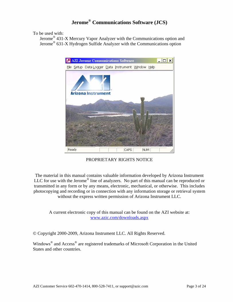
Jerome® Communications Software (JCS)
To be used with:
Jerome®
431-X Mercury Vapor Analyzer with the Communications option and
Jerome®
631-X Hydrogen Sulfide Analyzer with the Communications option
PROPRIETARY RIGHTS NOTICE
The material in this manual contains valuable information developed by Arizona Instrument
LLC for use with the Jerome®
line of analyzers. No part of this manual can be reproduced or
transmitted in any form or by any means, electronic, mechanical, or otherwise. This includes
photocopying and recording or in connection with any information storage or retrieval system
without the express written permission of Arizona Instrument LLC.
A current electronic copy of this manual can be found on the AZI website at:
www.azic.com/downloads.aspx
© Copyright 2000-2009, Arizona Instrument LLC. All Rights Reserved.
Windows®
and Access®
are registered trademarks of Microsoft Corporation in the United
States and other countries.

Page 4 of 24 AZI Customer Service 602-470-1414, 800-528-7411, or [email protected]
1. INTRODUCTION
The Jerome®
Communications Software (JCS) operates with the Jerome®
431-X Mercury
Vapor and Jerome®
631-X Hydrogen Sulfide Analyzers that have the Communications option
installed. The software can control instrument sampling for unattended continuous operation,
collect data, graph this data in real time and perform statistical analysis.
The software can also program the Jerome®
Data Logger, AZI P/N 6100-0010. This optional
accessory enables data storage during manual sampling or portable automatic sampling,
without being attached to a computer. The Data Logger initiates automatic sampling, triggers
alarms and stores data. The logged data may then be downloaded to the computer when it is
convenient.
The JCS software is menu-driven and easy to use. Each display screen is designed for clarity
with self-explanatory menu options. Select menu options using either a mouse/pointing
device or a standard keyboard. The user creates records, or files, for computer storage of
collected data. Data is easily retrieved for later viewing, graphing, printing or editing with
spreadsheet or word processing software (not provided). Data can be used for ongoing record
keeping or for fulfilling local regulatory requirements.
Before using this software, familiarization with the operation of the Jerome®
Hydrogen
Sulfide Analyzer or Mercury Vapor Analyzer is important. Prior to installation of this
software, familiarity with the personal computer and Windows®
operating system being used
is also recommended. If you have any questions about how to proceed, call AZI Customer
Service at (800) 528-7411 or (602) 470-1414 or send an e-mail to [email protected] for
assistance.
AZI Customer Service 602-470-1414, 800-528-7411, or [email protected] Page 5 of 24
2. SYSTEM REQUIREMENTS
Contents of the JCS Kit (AZI #Y990-0168)
Jerome®
Communications Software (on CD-ROM)
USB Security Key
JCS (Instrument/Data Logger/PC) Interface Cable, AZI #6000-1055
This user’s manual (also on the CD-ROM)
Files on the JCS Program CD-ROM
JCS installation program
JCS and instrument manuals current at the time the software shipped
System requirements, not included with the JCS Kit
Jerome®
431-X or 631-X with the Communications Option installed
Windows®
98 Second Edition, Windows®
ME, Windows®
NT, Windows®
2000 or
Windows®
XP
One available DB9/RS-232 serial port
One available USB port
Optional equipment:
Jerome®
Data Logger, AZI P/N 6100-0010 (to capture data without a computer
nearby)
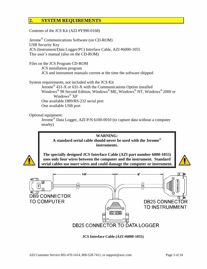
WARNING:
A standard serial cable should never be used with the Jerome®
instruments.
The specially designed JCS Interface Cable (AZI part number 6000-1055)
uses only four wires between the computer and the instrument. Standard
serial cables use more wires and could damage the computer or instrument.
JCS Interface Cable (AZI #6000-1055)
Page 6 of 24 AZI Customer Service 602-470-1414, 800-528-7411, or [email protected]
3. HARDWARE INSTALLATION
Please Note: Only the JCS Interface Cable should be installed at this time.
After the software is installed and operating, the security key will be installed
in an available USB port.
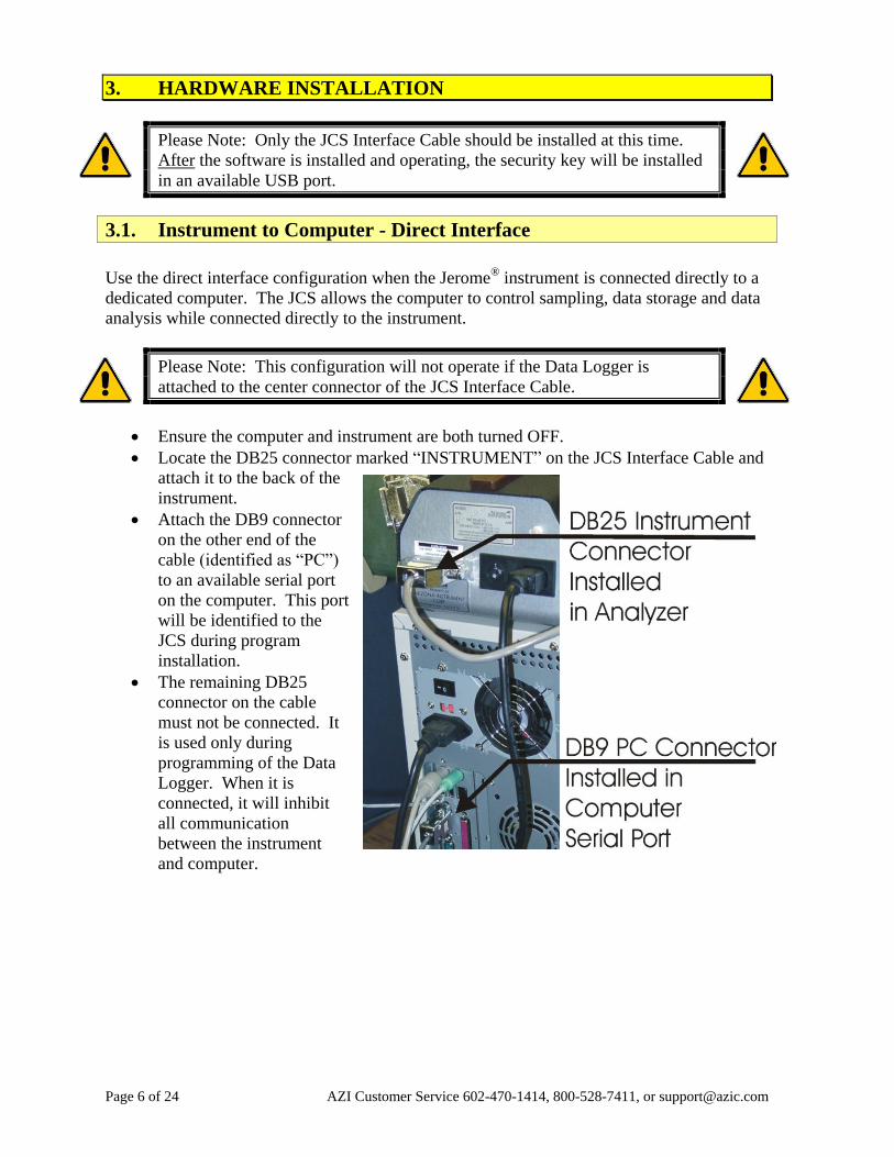
3.1. Instrument to Computer - Direct Interface
Use the direct interface configuration when the Jerome®
instrument is connected directly to a
dedicated computer. The JCS allows the computer to control sampling, data storage and data
analysis while connected directly to the instrument.
Please Note: This configuration will not operate if the Data Logger is
attached to the center connector of the JCS Interface Cable.
Ensure the computer and instrument are both turned OFF.
Locate the DB25 connector marked “INSTRUMENT” on the JCS Interface Cable and
attach it to the back of the
instrument.
Attach the DB9 connector
on the other end of the
cable (identified as “PC”)
to an available serial port
on the computer. This port
will be identified to the
JCS during program
installation.
The remaining DB25
connector on the cable
must not be connected. It
is used only during
programming of the Data
Logger. When it is
connected, it will inhibit
all communication
between the instrument
and computer.
AZI Customer Service 602-470-1414, 800-528-7411, or [email protected] Page 7 of 24
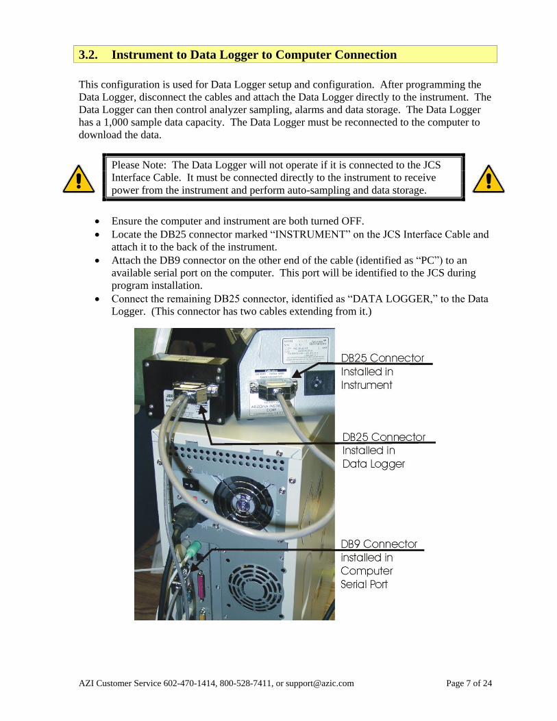
3.2. Instrument to Data Logger to Computer Connection
This configuration is used for Data Logger setup and configuration. After programming the
Data Logger, disconnect the cables and attach the Data Logger directly to the instrument. The
Data Logger can then control analyzer sampling, alarms and data storage. The Data Logger
has a 1,000 sample data capacity. The Data Logger must be reconnected to the computer to
download the data.
Please Note: The Data Logger will not operate if it is connected to the JCS
Interface Cable. It must be connected directly to the instrument to receive
power from the instrument and perform auto-sampling and data storage.
Ensure the computer and instrument are both turned OFF.
Locate the DB25 connector marked “INSTRUMENT” on the JCS Interface Cable and
attach it to the back of the instrument.
Attach the DB9 connector on the other end of the cable (identified as “PC”) to an
available serial port on the computer. This port will be identified to the JCS during
program installation.
Connect the remaining DB25 connector, identified as “DATA LOGGER,” to the Data
Logger. (This connector has two cables extending from it.)
Page 8 of 24 AZI Customer Service 602-470-1414, 800-528-7411, or [email protected]
4. SOFTWARE INSTALLATION
4.1. Starting the Software
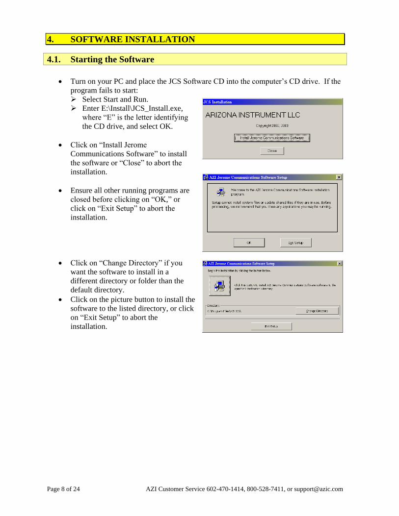
Turn on your PC and place the JCS Software CD into the computer’s CD drive. If the
program fails to start:
Select Start and Run.
Enter E:\Install\JCS_Install.exe,
where “E” is the letter identifying
the CD drive, and select OK.
Click on “Install Jerome
Communications Software” to install
the software or “Close” to abort the
installation.
Ensure all other running programs are
closed before clicking on “OK,” or
click on “Exit Setup” to abort the
installation.
Click on “Change Directory” if you
want the software to install in a
different directory or folder than the
default directory.
Click on the picture button to install the
software to the listed directory, or click
on “Exit Setup” to abort the
installation.
AZI Customer Service 602-470-1414, 800-528-7411, or [email protected] Page 9 of 24
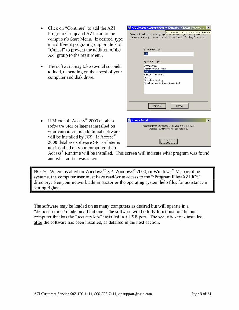
Click on “Continue” to add the AZI
Program Group and AZI icon to the
computer’s Start Menu. If desired, type
in a different program group or click on
“Cancel” to prevent the addition of the
AZI group to the Start Menu.
The software may take several seconds
to load, depending on the speed of your
computer and disk drive.
If Microsoft Access®
2000 database
software SR1 or later is installed on
your computer, no additional software
will be installed by JCS. If Access®
2000 database software SR1 or later is
not installed on your computer, then
Access®
Runtime will be installed. This screen will indicate what program was found
and what action was taken.
NOTE: When installed on Windows®
XP, Windows®
2000, or Windows®
NT operating
systems, the computer user must have read/write access to the "\Program Files\AZI JCS"
directory. See your network administrator or the operating system help files for assistance in
setting rights.
The software may be loaded on as many computers as desired but will operate in a
“demonstration” mode on all but one. The software will be fully functional on the one
computer that has the “security key” installed in a USB port. The security key is installed
after the software has been installed, as detailed in the next section.
Page 10 of 24 AZI Customer Service 602-470-1414, 800-528-7411, or [email protected]
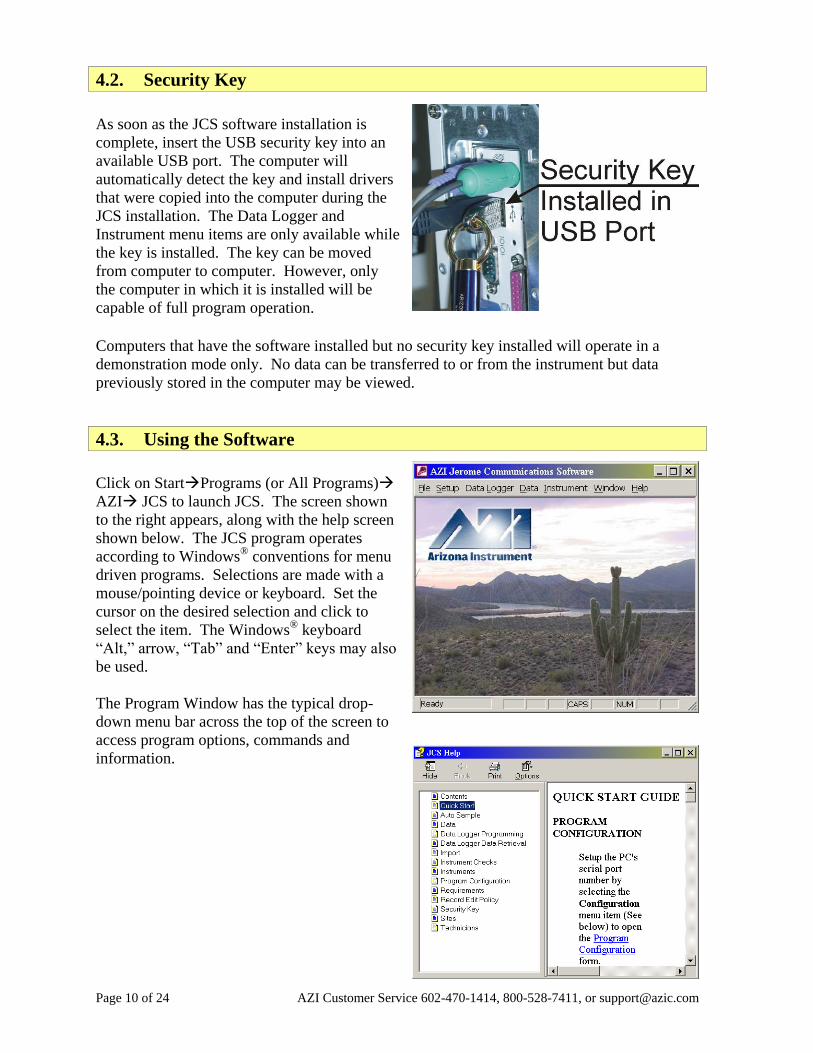
4.2. Security Key
As soon as the JCS software installation is
complete, insert the USB security key into an
available USB port. The computer will
automatically detect the key and install drivers
that were copied into the computer during the
JCS installation. The Data Logger and
Instrument menu items are only available while
the key is installed. The key can be moved
from computer to computer. However, only
the computer in which it is installed will be
capable of full program operation.
Computers that have the software installed but no security key installed will operate in a
demonstration mode only. No data can be transferred to or from the instrument but data
previously stored in the computer may be viewed.
4.3. Using the Software
Click on StartPrograms (or All Programs)
AZI JCS to launch JCS. The screen shown
to the right appears, along with the help screen
shown below. The JCS program operates
according to Windows®
conventions for menu
driven programs. Selections are made with a
mouse/pointing device or keyboard. Set the
cursor on the desired selection and click to
select the item. The Windows®
keyboard
“Alt,” arrow, “Tab” and “Enter” keys may also
be used.
The Program Window has the typical drop-
down menu bar across the top of the screen to
access program options, commands and
information.
AZI Customer Service 602-470-1414, 800-528-7411, or [email protected] Page 11 of 24
4.4. Program Revision Information
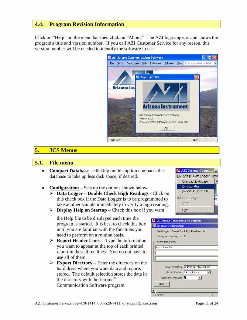
Click on “Help” on the menu bar then click on “About.” The AZI logo appears and shows the
program's title and version number. If you call AZI Customer Service for any reason, this
version number will be needed to identify the software in use.
5. JCS Menus
5.1. File menu
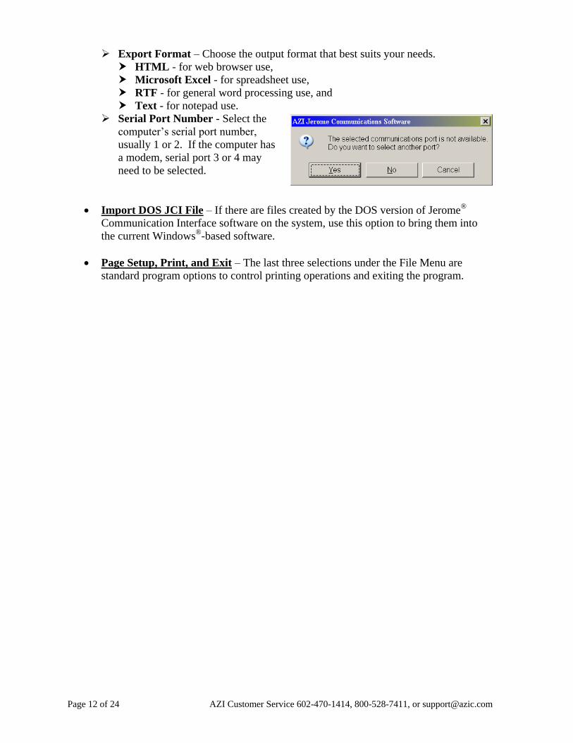
Compact Database – clicking on this option compacts the
database to take up less disk space, if desired.
Configuration – Sets up the options shown below.
Data Logger – Double Check High Readings - Click on
this check box if the Data Logger is to be programmed to
take another sample immediately to verify a high reading.
Display Help on Startup – Check this box if you want
the Help file to be displayed each time the
program is started. It is best to check this box
until you are familiar with the functions you
need to perform on a routine basis.
Report Header Lines – Type the information
you want to appear at the top of each printed
report in these three lines. You do not have to
use all of them.
Export Directory – Enter the directory on the
hard drive where you want data and reports
stored. The default selection stores the data in
the directory with the Jerome®
Communication Software program.
Page 12 of 24 AZI Customer Service 602-470-1414, 800-528-7411, or [email protected]
Export Format – Choose the output format that best suits your needs.
HTML - for web browser use,
Microsoft Excel - for spreadsheet use,
RTF - for general word processing use, and
Text - for notepad use.
Serial Port Number - Select the
computer’s serial port number,
usually 1 or 2. If the computer has
a modem, serial port 3 or 4 may
need to be selected.
Import DOS JCI File – If there are files created by the DOS version of Jerome®
Communication Interface software on the system, use this option to bring them into
the current Windows®
-based software.
Page Setup, Print, and Exit – The last three selections under the File Menu are
standard program options to control printing operations and exiting the program.
AZI Customer Service 602-470-1414, 800-528-7411, or [email protected] Page 13 of 24
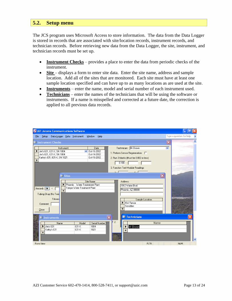
5.2. Setup menu
The JCS program uses Microsoft Access to store information. The data from the Data Logger
is stored in records that are associated with site/location records, instrument records, and
technician records. Before retrieving new data from the Data Logger, the site, instrument, and
technician records must be set up.
Instrument Checks – provides a place to enter the data from periodic checks of the
instrument.
Site – displays a form to enter site data. Enter the site name, address and sample
location. Add all of the sites that are monitored. Each site must have at least one
sample location specified and can have up to as many locations as are used at the site.
Instruments – enter the name, model and serial number of each instrument used.
Technicians – enter the names of the technicians that will be using the software or
instruments. If a name is misspelled and corrected at a future date, the correction is
applied to all previous data records.
Page 14 of 24 AZI Customer Service 602-470-1414, 800-528-7411, or [email protected]
5.3. Data Logger menu
The Data Logger is used to collect the data from the instrument, but first it must be
programmed.
To program the Data Logger:
Connect the JCS Interface Cable as follows:
Attach the connector marked “DATA LOGGER” to the Data Logger.
Attach the connector marked “PC” to the computer.
Attach the connector marked “INSTRUMENT” to the instrument.
Turn the instrument ON.
In JCS, click on the “Data Logger”
drop-down menu, and then click on
“Program.”
The Program Menu allows setting of
the sample interval and alarm setpoint
value into the Data Logger.
Do not use a short Sample Interval
that would require more than 2
regenerations per day. Try a 10 to
15 minute sample interval initially.
Set the Alarm Setpoint if desired or
leave it blank. A blank alarm
setpoint has the effect of turning off
the alarm.
Click on the Program button to set
the values into the Data Logger.
Disconnect the JCS Interface Cable from the instrument and Data Logger.
Attach the Data Logger directly to the instrument.
The Data Logger can be left unpowered for a few hours without losing its time
clock. Turn the instrument on every few hours for a few minutes to power the
Data Logger and retain the clock and programming.
When you are ready to begin sampling:
Turn the instrument ON
Press the sample button.
When finished sampling:
Turn the instrument off.
Remove the Data Logger from the instrument and attach it to the JCS Interface
Cable connector marked “DATA LOGGER.”
Ensure the JCS Interface Cable’s “PC” connector is still attached to the computer.
Connect the JCS Interface Cable connector marked “INSTRUMENT” to the
instrument.
Turn the instrument ON.
AZI Customer Service 602-470-1414, 800-528-7411, or [email protected] Page 15 of 24
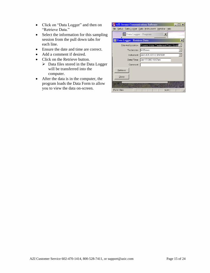
Click on “Data Logger” and then on
“Retrieve Data.”
Select the information for this sampling
session from the pull down tabs for
each line.
Ensure the date and time are correct.
Add a comment if desired.
Click on the Retrieve button.
Data files stored in the Data Logger
will be transferred into the
computer.
After the data is in the computer, the
program loads the Data Form to allow
you to view the data on-screen.
Page 16 of 24 AZI Customer Service 602-470-1414, 800-528-7411, or [email protected]
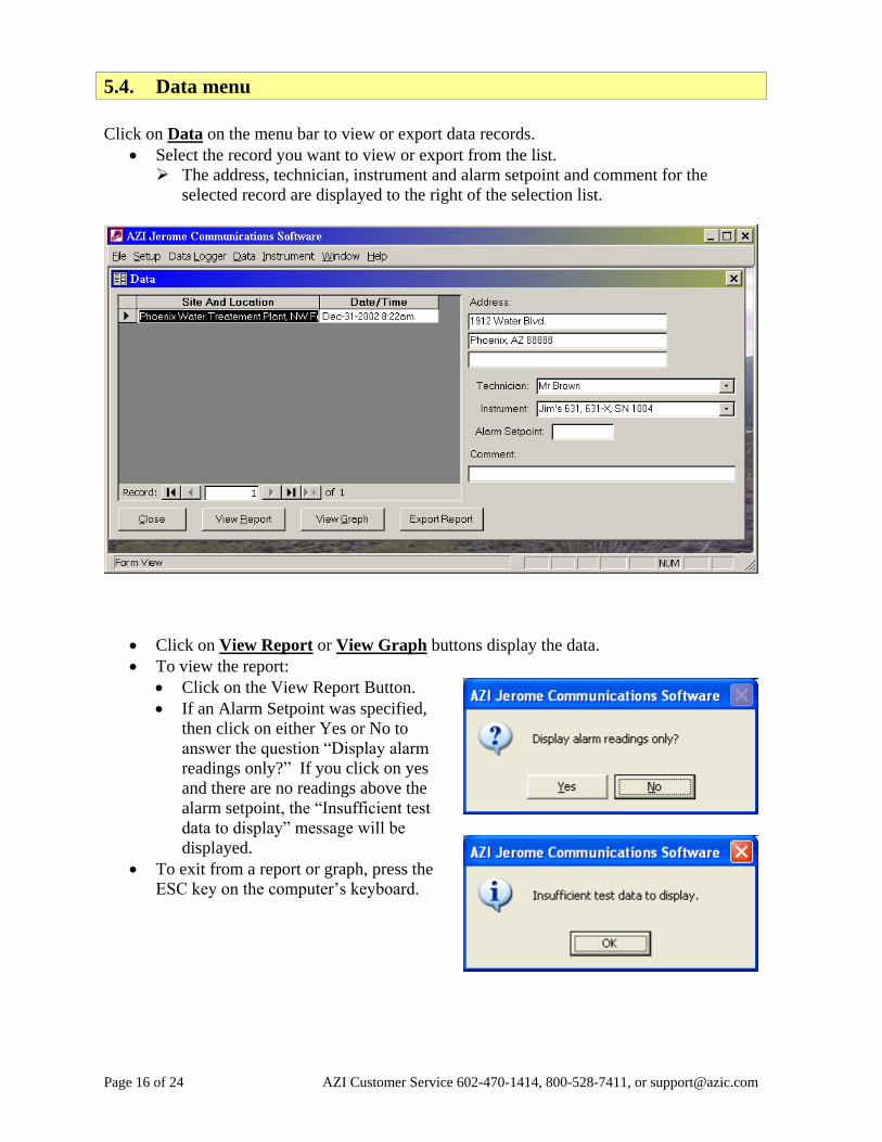
5.4. Data menu
Click on Data on the menu bar to view or export data records.
Select the record you want to view or export from the list.
The address, technician, instrument and alarm setpoint and comment for the
selected record are displayed to the right of the selection list.
Click on View Report or View Graph buttons display the data.
To view the report:
Click on the View Report Button.
If an Alarm Setpoint was specified,
then click on either Yes or No to
answer the question “Display alarm
readings only?” If you click on yes
and there are no readings above the
alarm setpoint, the “Insufficient test
data to display” message will be
displayed.
To exit from a report or graph, press the
ESC key on the computer’s keyboard.
AZI Customer Service 602-470-1414, 800-528-7411, or [email protected] Page 17 of 24
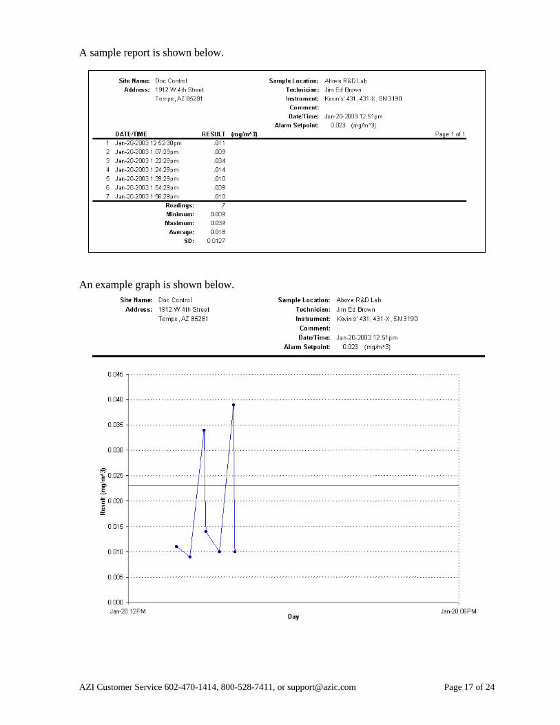
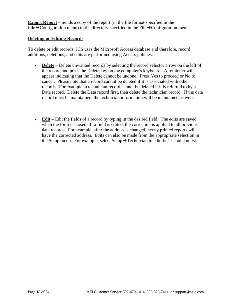
A sample report is shown below.
An example graph is shown below.
Page 18 of 24 AZI Customer Service 602-470-1414, 800-528-7411, or [email protected]
Export Report – Sends a copy of the report (in the file format specified in the
FileConfiguration menu) to the directory specified in the FileConfiguration menu.
Deleting or Editing Records
To delete or edit records, JCS uses the Microsoft Access database and therefore, record
additions, deletions, and edits are performed using Access policies:
Delete – Delete unwanted records by selecting the record selector arrow on the left of
the record and press the Delete key on the computer’s keyboard. A reminder will
appear indicating that the Delete cannot be undone. Press Yes to proceed or No to
cancel. Please note that a record cannot be deleted if it is associated with other
records. For example: a technician record cannot be deleted if it is referred to by a
Data record. Delete the Data record first, then delete the technician record. If the data
record must be maintained, the technician information will be maintained as well.
Edit – Edit the fields of a record by typing in the desired field. The edits are saved
when the form is closed. If a field is edited, the correction is applied to all previous
data records. For example, after the address is changed, newly printed reports will
have the corrected address. Edits can also be made from the appropriate selection in
the Setup menu. For example, select SetupTechnician to edit the Technician list.
AZI Customer Service 602-470-1414, 800-528-7411, or [email protected] Page 19 of 24
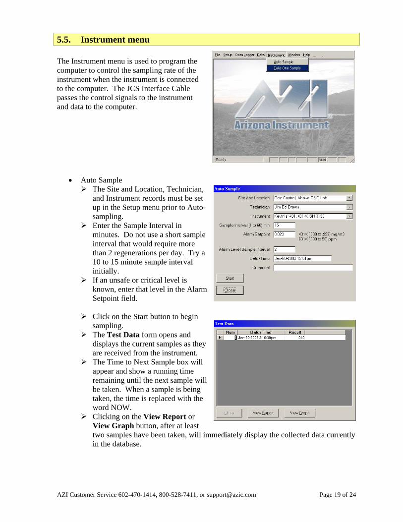
5.5. Instrument menu
The Instrument menu is used to program the
computer to control the sampling rate of the
instrument when the instrument is connected
to the computer. The JCS Interface Cable
passes the control signals to the instrument
and data to the computer.
Auto Sample
The Site and Location, Technician,
and Instrument records must be set
up in the Setup menu prior to Auto-
sampling.
Enter the Sample Interval in
minutes. Do not use a short sample
interval that would require more
than 2 regenerations per day. Try a
10 to 15 minute sample interval
initially.
If an unsafe or critical level is
known, enter that level in the Alarm
Setpoint field.
Click on the Start button to begin
sampling.
The Test Data form opens and
displays the current samples as they
are received from the instrument.
The Time to Next Sample box will
appear and show a running time
remaining until the next sample will
be taken. When a sample is being
taken, the time is replaced with the
word NOW.
Clicking on the View Report or
View Graph button, after at least
two samples have been taken, will immediately display the collected data currently
in the database.
Page 20 of 24 AZI Customer Service 602-470-1414, 800-528-7411, or [email protected]
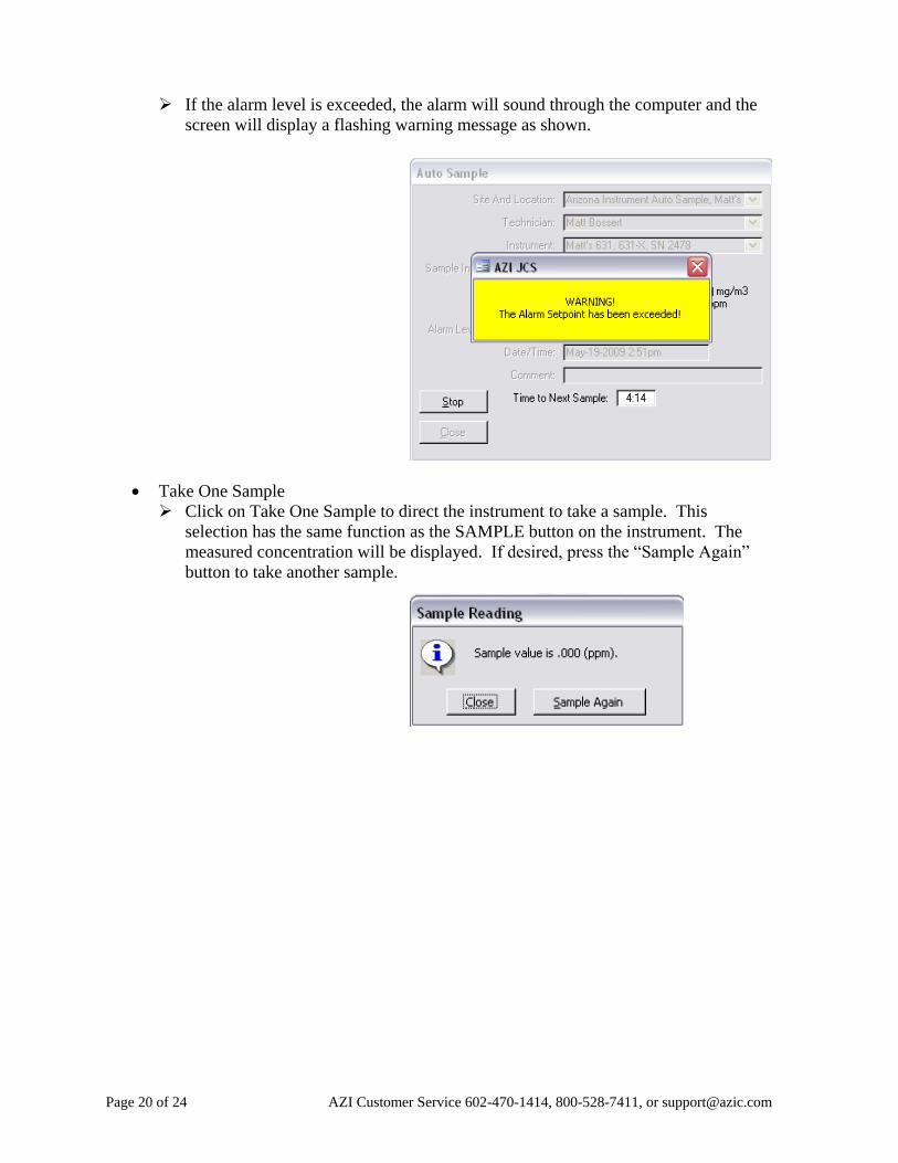
If the alarm level is exceeded, the alarm will sound through the computer and the
screen will display a flashing warning message as shown.
Take One Sample
Click on Take One Sample to direct the instrument to take a sample. This
selection has the same function as the SAMPLE button on the instrument. The
measured concentration will be displayed. If desired, press the “Sample Again”
button to take another sample.
AZI Customer Service 602-470-1414, 800-528-7411, or [email protected] Page 21 of 24
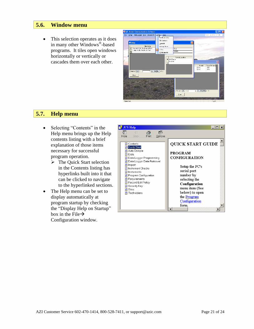
5.6. Window menu
This selection operates as it does
in many other Windows®
-based
programs. It tiles open windows
horizontally or vertically or
cascades them over each other.
5.7. Help menu
Selecting “Contents” in the
Help menu brings up the Help
contents listing with a brief
explanation of those items
necessary for successful
program operation.
The Quick Start selection
in the Contents listing has
hyperlinks built into it that
can be clicked to navigate
to the hyperlinked sections.
The Help menu can be set to
display automatically at
program startup by checking
the “Display Help on Startup”
box in the File
Configuration window.
Page 22 of 24 AZI Customer Service 602-470-1414, 800-528-7411, or [email protected]
6. Operation
6.1. Instrument operation from the computer
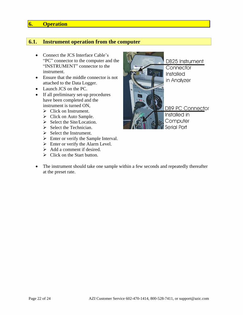
Connect the JCS Interface Cable’s
“PC” connector to the computer and the
“INSTRUMENT” connector to the
instrument.
Ensure that the middle connector is not
attached to the Data Logger.
Launch JCS on the PC.
If all preliminary set-up procedures
have been completed and the
instrument is turned ON,
Click on Instrument.
Click on Auto Sample.
Select the Site/Location.
Select the Technician.
Select the Instrument.
Enter or verify the Sample Interval.
Enter or verify the Alarm Level.
Add a comment if desired.
Click on the Start button.
The instrument should take one sample within a few seconds and repeatedly thereafter
at the preset rate.
AZI Customer Service 602-470-1414, 800-528-7411, or [email protected] Page 23 of 24
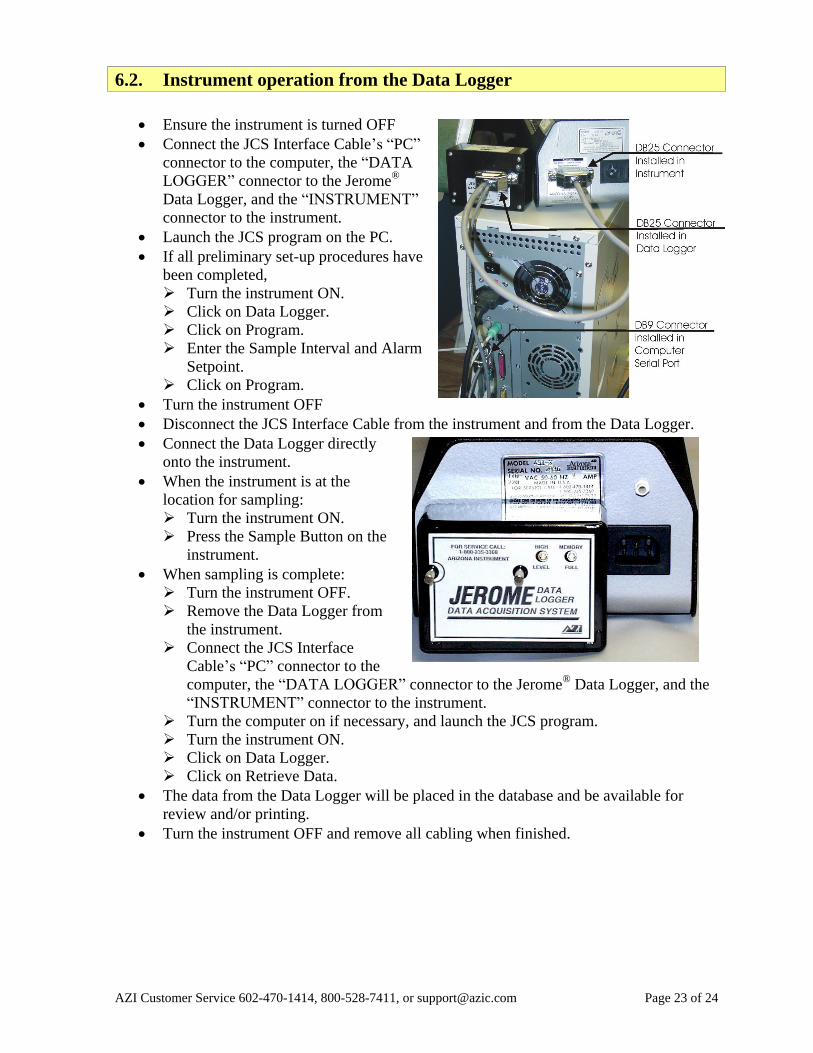
6.2. Instrument operation from the Data Logger
Ensure the instrument is turned OFF
Connect the JCS Interface Cable’s “PC”
connector to the computer, the “DATA
LOGGER” connector to the Jerome®
Data Logger, and the “INSTRUMENT”
connector to the instrument.
Launch the JCS program on the PC.
If all preliminary set-up procedures have
been completed,
Turn the instrument ON.
Click on Data Logger.
Click on Program.
Enter the Sample Interval and Alarm
Setpoint.
Click on Program.
Turn the instrument OFF
Disconnect the JCS Interface Cable from the instrument and from the Data Logger.
Connect the Data Logger directly
onto the instrument.
When the instrument is at the
location for sampling:
Turn the instrument ON.
Press the Sample Button on the
instrument.
When sampling is complete:
Turn the instrument OFF.
Remove the Data Logger from
the instrument.
Connect the JCS Interface
Cable’s “PC” connector to the
computer, the “DATA LOGGER” connector to the Jerome®
Data Logger, and the
“INSTRUMENT” connector to the instrument.
Turn the computer on if necessary, and launch the JCS program.
Turn the instrument ON.
Click on Data Logger.
Click on Retrieve Data.
The data from the Data Logger will be placed in the database and be available for
review and/or printing.
Turn the instrument OFF and remove all cabling when finished.

Page 24 of 24 AZI Customer Service 602-470-1414, 800-528-7411, or [email protected]
TRADEMARK AND COPYRIGHT PROTECTION
Jerome®
, Arizona Instrument®
and the stylized AZI are all registered trademarks of Arizona
Instrument LLC. Instrument firmware and software is copyright protected.
© Copyright 2000-2009, Arizona Instrument LLC. All Rights Reserved.
Windows®
and Access®
are registered trademarks of Microsoft Corporation in the United
States and other countries.
Arizona Instrument LLC
Jerome® Communication Software Installation and Operation Manual
AZI P/N: 700-0042-B
May 2009
If you have any questions regarding the operation of this instrument, please call 800-528-
7411, 602-470-1414, fax 480-804-0656 or send e-mail to [email protected].
Arizona Instrument LLC
3375 N Delaware Street
Chandler, AZ 85225
(800) 528-7411
(602) 470-1414
Fax (480) 804-0656
http://www.azic.com
email:
[email protected] - General
[email protected] - International
[email protected] - Customer Support