Embed Size (px)
Citation preview
®
16633 Foltz Parkway ● Strongsville, OH 44149 USA Telephone: (440) 572-1500 ● Fax: (440) 238-8828 www.jerguson.com ● [email protected]
The innovative use of repelling
magnetic fields eliminates
mechanical elements that are
prone to failure in high
temperatures, extreme
vibration, or simply fatigue over
time.
External Cage
Displacer Operated
Magnetic Level Switch
Unique 3 magnet latching.
No springs…No problem.
(Series JX) (Series JB)
Jerguson’s Tri-Magnet Level Switches
deliver failure-free performance.
“The new switches are very rugged and
dependable, and most importantly, they are
mercury-free and safe for the environment.
Dealing with spilled mercury is an extremely
difficult task, but it is one we don’t have to
worry about with these new switches. The
Jerguson Tri-Magnet Level Switches have
been in operation in our facility since May
2007.”
-Maintenance Superintendent,
Major Utility Power Generation Plant
The Tri-Magnet Level Switch was endurance tested to over 850,000 cycles without failure.
Section: Bulletin:
Date: Supercedes:
JS100 JS100.04 4/2017 12/2014
FEATURES
• Tri-Magnet Switching for
Unparalleled Reliability
• Vibration Resistant
• Sealed or Flanged Cage
• 316 Stainless Steel Trim
• ASME B31.1 & B31.3 Design

ASME B16.5
WELD NECK
FLANGES
REINFORCED
BRANCH
CONNECTIONS
ALL FULL
PENETRATION
WELDS
External Cage Displacer Operated Magnetic Level Switch
JERGUSON® LEVEL SWITCHES
THE SWITCH MECHANISM
Principle of Operation
The switch mechanism is based on a unique three-dimensional magnet
design where the snap action is accomplished by the utilization of
magnetic repulsion and attraction. The primary magnet mounted on the
float rod causes the secondary magnet to rotate as it passes up and
down. The tertiary switch magnet is repelled by the secondary and
snaps to the opposite side. This causes the cradle to pivot, moving the
push rods, which operate the switch contacts. The result is positive
snap action interlock switching…no springs…no spring problems!
Schematic showing three-magnet system
Applications
The flanged chamber construction of this
X series range of vertical controls makes
them a very serviceable level control
solution for petrochemical, power
generation and OEM applications.
The unique three-magnet system
provides reliable switching for
applications such as level alarm, safety
shutdown and pump control in product
storage tanks, gas scrubbers, process
vessels, and high pressure steam
generators.
Single models are available. Chambers
are designed to ASME B31.1, Power
Piping Code, and ASME B31.3,
Chemical Plant and Petroleum Refinery
Piping Code.
Options:
• Stainless Steel Chamber
• Low temperature chamber below -20⁰F
• High temperature chrome-moly chamber
• Certified to B31.3 or B31.1
• Non-destructive testing: radiographic,
ultrasonic, magnetic particle, dye
penetrant
• Epoxy paint finish (FP-18)
• Extended NEMA 4 switch enclosure
housing up to 3 SPDT switch
mechanisms or 3 DPDT switch
mechanisms
• Vent connection
• Specific gravity down to .40
• NACE specification MR-0175
4 Contact Type D4, X4, P4, H4, E4
2 x S.P.S.T
AA Make on Rise
BB Make on Fall
Link for SPDT/SPCO
8 Contact Type D8, X8, P8, H8, E8
D.P.D.T.
4 x S.P.S.T.
AA Make on Rise
BB Make on Fall
Link for DPDT/DPCONote: Max. temperature of displacer operated level switch = 400°F
THE DISPLACER CHAMBER
Type
X4, X8
D4, D8
H4, H8
P4, P8
Encapsulated - 5 amp switch mechanism is sealed / encapsulated inside alluminum
housing, suitable for temperatures to 850°FE4, E8
Choice of Switch Mechanisms
Low current - 0.25 amp gold-plated contact switch mechanism for use in intrinsically
safe or low power circuits up to 750⁰F
Hermetically sealed - 5 amp mechanisms suitable for temperatures up to 480°F,
contaminated atmosphere environments and intrinsically safe circuits. All moving parts
and contacts enclosed in an inert gas filled stainless steel enclosure.
High temperature - 5 amp mechanisms for high temperature applications up to 750⁰F
General purpose - 10 amp mechanisms for general purpose duties up to 480⁰F
Application
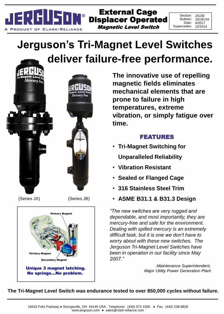
DIMENSIONAL AND OPERATING LEVEL DATA
ENCLOSURE DIMENSIONAL DATA
MATERIALS OF CONSTRUCTION
NOTE: All flange nipples are 1” NPS as standard
All mechanical level devices are warranted free of defects in materials and workmanship for five
years from the date of original factory shipment.
If returned within the stated warranty period, and upon factory inspection the cause of the claim is
determined to be covered under the warranty, at option, the device will be repaired or replaced
without cost to the purchaser (or owner), other than transportation.
Jerguson® shall not be liable for mis-application, labor claims, direct or consequential damage or
expense arising from the installation or use of the equipment. There are no other warranties
expressed or implied.
OUR WARRANTY
Chamber Pipe
Iconel 600/316 SST
ASTM A194-2H
ASTM Z193-B7
ASTM A182F316
ASTM A403 WP-316
316 SST 316 SSTDisplacer
ASTM A193-B7
Materials of Construction Stainless Steel ChamberCarbon Steel Chamber
ASTM A105
ASTM A234
ASTM A106 GrB
Technical Specifications Designed in accordance w ith the requirements of B31.1 & B31.3. Pressure tested to 1.5 x maximum w orking pressures.
Spring/Trim
Nuts
Studs
Flanges/Fittings
Top/Bottom Caps
ASTM A312 316
Iconel 600/316 SST
ASTM A194-2H
12"
13 1/4"
Weather-proof
Explosion-proof
SA4
SA7
NEMA 4
NEMA 4 & 7
3 3/8"
3 3/8"
1" NPT
1" NPT
Weatherproof
Rating
Switch
Adjustment
Conduit
ThreadHeight GDutyType
C1 D E
8 1/2" 16" 3 1/4" 6" 2" 0.56" 14" 5 1/2" 5 3/4"
14" 16" 3 1/4" 6" 2 7/8" 0.56" 14" 10 1/2" 9 1/4"
14" 16" 3 1/4" 6" 2 7/8" 0.56" 14" 10 1/2" 9 3/4"
14" 16" 3 1/4" 6" 2 7/8" 0.56" 14" 10 1/2" 10 1/2"
14" 16" 3 1/4" 6" 2 7/8" 0.56" 14" 10 1/2" 11 1/2"
14" 16" 4" 7" 2 1/4" 0.56" 14" 11 1/2" 11 1/2"
JBC4D & JXC4D
JBC5D & JXC5D
Hi
AlarmFlanged
JBC6D & JXC6D
JBC2D & JXC2D
BA
Chamber
Type X
JBC1D & JXC1D
JBC3D & JXC3D
Notes: 1) Flanged dimensions apply for R.F. process connections up to 2" - 600#.
2) Switch actuation levels are at minimum S.G.
3) C1 = Single Switch : Process C/L to rising trip point of switch.
4) D = Switch Deadband, Distance Between Rising Trip & Falling Reset.
All dimenstions in inches. Dimensions are for reference only, and must be certif ied upon order. All dimensions based 1" reinforced fittings.
NPT
or S/WFlanged
NPT or
S/W
Chamber
Type BC-C④
F
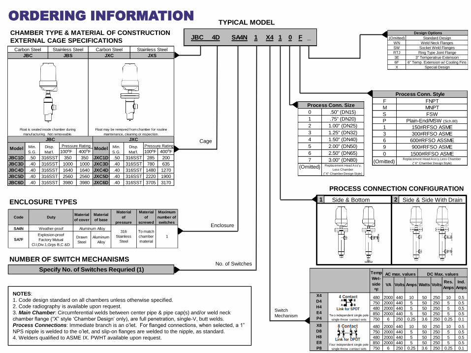
TYPICAL MODEL
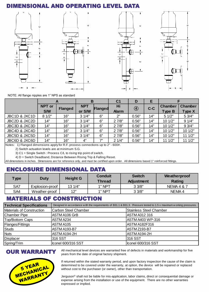
CHAMBER TYPE & MATERIAL OF CONSTRUCTION
EXTERNAL CAGE SPECIFICATIONS
Cage
ENCLOSURE TYPES
Enclosure
ORDERING INFORMATION
NUMBER OF SWITCH MECHANISMS No. of Switches
Switch
Mechanism
PROCESS CONNECTION CONFIGURATION
480 2000 440 10 50 250 10 0.5
750 2000 440 5 50 250 5 0.5
480 2000 440 5 50 250 5 0.5
850 2000 440 5 50 250 5 0.5
750 6 250 0.25 3.6 250 0.25 0.1
480 2000 440 10 50 250 10 0.5
750 2000 440 5 50 250 5 0.5
480 2000 440 5 50 250 5 0.5
850 2000 440 5 50 250 5 0.5
750 6 250 0.25 3.6 250 0.25 0.1
X4
D4
H4
E4
P4
X8
D8
H8
E8
P8
Temp
Wet-
side
⁰F
AC max. values
VA AmpsVolts
Tw o independent single pole
single throw contact sets
Four independent single pole
single throw contact sets
Res.
AmpsVoltsWatts
DC Max. values
Ind.
Amps
0 .50" (DN15)
1 .75" (DN20)
2 1.00" (DN25)
3 1.25" (DN32)
4 1.50" (DN40)
5 2.00" (DN50)
6 2.50" (DN65)
7 3.00" (DN80)
(Omitted) Replacement Head Ass'y,
Less Chamber
("X" Chamber Design Style)
Process Conn. Size
NOTES:
1. Code design standard on all chambers unless otherwise specified.
2. Code radiography is available upon request.
3. Main Chamber: Circumferential welds between center pipe & pipe cap(s) and/or weld neck
chamber flange (“X” style ‘Chamber Design’ only), are full penetration, single-V, butt welds.
Process Connections: Immediate branch is an o’let. For flanged connections, when selected, a 1”
NPS nipple is welded to the o’let, and slip-on flanges are welded to the nipple, as standard.
4. Welders qualified to ASME IX. PWHT available upon request.
JBC
Carbon Steel
Float is sealed inside chamber during
manufacturing. Not removeable.
Float may be removed from chamber for routine
maintenance, cleaning or inspection.
JXS
Stainless Steel
JXC
Carbon Steel
JBS
Stainless Steel
F FNPT
M MNPT
S FSW
P Plain-End/MSW (Sch.80)
1 150#RFSO ASME
3 300#RFSO ASME
6 600#RFSO ASSME
9 900#RFSO ASME
0 1500#RFSO ASME
(Omitted)Replacement Head Ass'y, Less Chamber
("X" Chamber Design Style)
Process Conn. Style
100⁰F 400⁰F 100⁰F 400⁰F
JBC1D .50 316SST 350 350 JXC1D .50 316SST 285 200
JBC3D .40 316SST 1000 1000 JXC3D .40 316SST 780 635
JBC4D .40 316SST 1640 1640 JXC4D .40 316SST 1480 1270
JBC5D .40 316SST 2560 2560 JXC5D .40 316SST 2220 1900
JBC6D .40 316SST 3980 3980 JXC6D .40 316SST 3705 3170
Disp.
Mat'l.
Min.
S.G.
Disp.
Mat'l.
JBC JXC
ModelPressure Rating
ModelPressure RatingMin.
S.G.
Code DutyMaterial
of cover
Material
of base
Material
of
pressure
Material
of
screwed
Maximum
number of
switches
SA4N Weather-proof
SA7F
Explosion-proof
Factory Mutual
Cl.I,Div.1,Grps B,C &D
Drawn
Steel
Aluminum
Alloy
Aluminum Alloy316
Stainless
Steel
To match
chamber
material
1
Specify No. of Switches Requried (1)
JBC 4D SA4N 1 X4 1 0 F _
Side & Bottom 1 Side & Side With Drain 2
(Omitted) Standard Design
WN Weld Neck Flanges
SW Socket Weld Flanges
RTJ Ring Type Joint Flange
3E 3" Temperatrue Extension
6F 6" Temp. Extension w/ Cooling Fins
X Special Design
Design Options
16633 Foltz Parkway ● Strongsville, OH 44149 USA Telephone: (440) 572-1500 ● Fax: (440) 238-8828 www.jerguson.com ● [email protected]
External Cage Displacer Operated Magnetic Level Switch
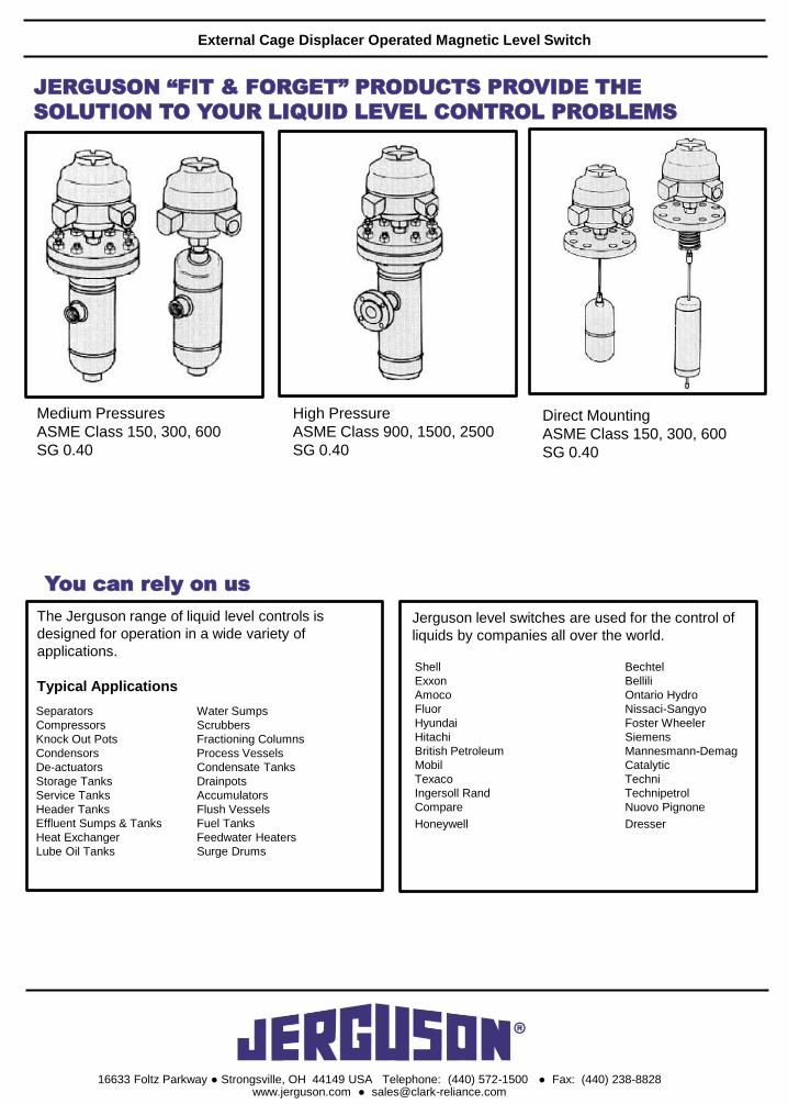
JERGUSON “FIT & FORGET” PRODUCTS PROVIDE THE
SOLUTION TO YOUR LIQUID LEVEL CONTROL PROBLEMS
Medium Pressures
ASME Class 150, 300, 600
SG 0.40
High Pressure
ASME Class 900, 1500, 2500
SG 0.40
Direct Mounting
ASME Class 150, 300, 600
SG 0.40
You can rely on us
The Jerguson range of liquid level controls is
designed for operation in a wide variety of
applications.
Typical Applications
Separators
Compressors
Knock Out Pots
Condensors
De-actuators
Storage Tanks
Service Tanks
Header Tanks
Effluent Sumps & Tanks
Heat Exchanger
Lube Oil Tanks
Water Sumps
Scrubbers
Fractioning Columns
Process Vessels
Condensate Tanks
Drainpots
Accumulators
Flush Vessels
Fuel Tanks
Feedwater Heaters
Surge Drums
Jerguson level switches are used for the control of
liquids by companies all over the world.
Shell Bechtel
Exxon Bellili
Amoco Ontario Hydro
Fluor Nissaci-Sangyo
Hyundai Foster Wheeler
Hitachi Siemens
British Petroleum Mannesmann-Demag
Mobil Catalytic
Texaco Techni
Ingersoll Rand Technipetrol
Compare Nuovo Pignone
Honeywell Dresser

16633 Foltz Parkway ● Strongsville, OH 44149 USA Telephone: (440) 572-1500 ● Fax: (440) 238-8828 www.clark-reliance.com ● [email protected]