Embed Size (px)
Citation preview

JEPPIAAR ENGINEERING COLLEGE
DEPARTMENT OF COMPUTER SCIENCE & ENGINEERING
CS6504
COMPUTER GRAPHICS
QUESTION BANK
III YEAR A & B / BATCH: 2015 -2019
VISION OF INSTITUTION
To build Jeppiaar Engineering College as an Institution of Academic Excellence in Technical
education and Management education and to become a World Class University.
MISSION OF INSTITUTION
M1 To excel in teaching and learning, research and innovation by promoting the principles
of scientific analysis and creative thinking
M2 To participate in the production, development and dissemination of knowledge and
interact with national and international communities
M3 To equip students with values, ethics and life skills needed to enrich their lives and
enable them to meaningfully contribute to the progress of society
M4
To prepare students for higher studies and lifelong learning, enrich them with the
practical and entrepreneurial skills necessary to excel as future professionals and
contribute to Nation’s economy
PROGRAM OUTCOMES (POs)
PO1 Engineering knowledge: Apply the knowledge of mathematics, science, engineering
fundamentals, and an engineering specialization to the solution of computer science
engineering problems. PO2 Problem analysis: Identify, formulate, review research literature, and analyze complex
engineering problems reaching substantiated conclusions using first principles of
mathematics, natural sciences, and engineering sciences.
PO3
Design/development of solutions: Design solutions for complex engineering problems and
design system components or processes that meet the specified needs with appropriate
consideration for the public health and safety, and the cultural, societal, and environmental
considerations. PO4 Conduct investigations of complex problems: Use research-based knowledge and research
methods including design of experiments, analysis and interpretation of data, and synthesis of
the information to provide valid conclusions. PO5 Modern tool usage: Create, select, and apply appropriate techniques, resources, and modern
engineering and IT tools including prediction and modeling to complex engineering activities
with an understanding of the limitations. PO6 The engineer and society: Apply reasoning informed by the contextual knowledge to assess
societal, health, safety, legal and cultural issues and the consequent responsibilities relevant
to the professional engineering practice.

PO7 Environment and sustainability: Understand the impact of the professional engineering
solutions in societal and environmental contexts, and demonstrate the knowledge of, and
need for sustainable development. PO8 Ethics: Apply ethical principles and commit to professional ethics and responsibilities and
norms of the engineering practice.
PO9 Individual and team work: Function effectively as an individual, and as a member or leader
in diverse teams, and in multidisciplinary settings.
PO10
Communication: Communicate effectively on complex engineering activities with the
engineering community and with society at large, such as, being able to comprehend and
write effective reports and design documentation, make effective presentations, and give and
receive clear instructions. PO11
Project management and finance: Demonstrate knowledge and understanding of the
engineering and management principles and apply these to one’s own work, as a member and
leader in a team, to manage projects and in multidisciplinary environments.
PO12 Life-long learning: Recognize the need for, and have the preparation and ability to engage in
independent and life-long learning in the broadest context of technological change.
VISION OF DEPARTMENT:
To emerge as a globally prominent department, developing ethical computer professionals,
innovators and entrepreneurs with academic excellence through quality education and research.
MISSION OF DEPARTMENT
M1
To create computer professionals with an ability to identify and formulate the engineering
problems and also to provide innovative solutions through effective teaching learning
process.
M2 To strengthen the core-competence in computer science and engineering and to create an
ability to interact effectively with industries.
M3 To produce engineers with good professional skills, ethical values and life skills for the
betterment of the society.
M4 To encourage students towards continuous and higher level learning on technological
advancements and provide a platform for employment and self-employment.
PROGRAMME EDUCATIONAL OBJECTIVES (PEOs)
PEO 01: To address the real time complex engineering problems using innovative approach
with strong core computing skills.
PEO 02: To apply core-analytical knowledge and appropriate techniques and provide solutions
to real time challenges of national and global society.
PEO 03: Apply ethical knowledge for professional excellence and leadership for the betterment
of the society.
PEO 04: Develop life-long learning skills needed for better employment and entrepreneurship.
PROGRAMME SPECIFIC OUTCOME (PSOs)
PSO1 – An ability to understand the core concepts of computer science and engineering and to
enrich problem solving skills to analyze, design and implement software and hardware based
systems of varying complexity.
PSO2 - To interpret real-time problems with analytical skills and to arrive at cost effective and
optimal solution using advanced tools and techniques.
PSO3 - An understanding of social awareness and professional ethics with practical proficiency
in the broad area of programming concepts by lifelong learning to inculcate employment and
entrepreneurship skills.
SYLLABUS
UNIT I INTRODUCTION 9
Survey of computer graphics, Overview of graphics systems – Video display devices,
Raster scan systems, Random scan systems, Graphics monitors and Workstations, Input devices,
Hard copy Devices, Graphics Software; Output primitives – points and lines, line drawing
algorithms, loading the frame buffer, line function; circle and ellipse generating algorithms; Pixel
addressing and object geometry, filled area primitives.
UNIT II TWO DIMENSIONAL GRAPHICS 9
Two dimensional geometric transformations – Matrix representations and homogeneous
coordinates, composite transformations; Two dimensional viewing – viewing pipeline, viewing
coordinate reference frame; widow-to-viewport coordinate transformation, Two dimensional
viewing functions; clipping operations – point, line, and polygon clipping algorithms.
UNIT III THREE DIMENSIONAL GRAPHICS 10
Three dimensional concepts; Three dimensional object representations – Polygon
surfaces- Polygon tables- Plane equations - Polygon meshes; Curved Lines and surfaces,
Quadratic surfaces; Blobby objects; Spline representations – Bezier curves and surfaces -B-
Spline curves and surfaces.
TRANSFORMATION AND VIEWING: Three dimensional geometric and modeling
transformations – Translation, Rotation, Scaling, composite transformations; Three dimensional
viewing – viewing pipeline, viewing coordinates, Projections, Clipping; Visible surface detection
methods.
UNIT IV ILLUMINATION AND COLOUR MODELS 7
Light sources - basic illumination models – halftone patterns and dithering techniques;
Properties of light - Standard primaries and chromaticity diagram; Intuitive colour concepts -
RGB colour model -YIQ colour model - CMY colour model - HSV colour model - HLS colour
model; Colour selection.
UNIT V ANIMATIONS & REALISM 10
ANIMATION GRAPHICS: Design of Animation sequences – animation function –
raster animation –key frame systems – motion specification –morphing – tweening.
COMPUTER GRAPHICS REALISM: Tiling the plane – Recursively defined curves – Koch
curves – C curves – Dragons –space filling curves – fractals – Grammar based models – fractals
– turtle graphics – ray tracing.

TEXT BOOKS:
1. John F. Hughes, Andries Van Dam, Morgan Mc Guire ,David F. Sklar , James D. Foley,
Steven K. Feiner and Kurt Akeley ,”Computer Graphics: Principles and Practice”, , 3rd
Edition, Addison Wesley Professional,2013. (UNIT I, II, III, IV).
2. Donald Hearn and Pauline Baker M, “Computer Graphics", Prentice Hall, New Delhi,
2007(UNIT V).
REFERENCES:
1. Donald Hearn and M. Pauline Baker, Warren Carithers,“Computer Graphics With Open
GL”, 4 th Edition, Pearson Education, 2010.
2. Jeffrey McConnell, “Computer Graphics: Theory into Practice”, Jones and Bartlett
Publishers, 2006.
3. Hill F S Jr., "Computer Graphics", Maxwell Macmillan” , 1990.
4. Peter Shirley, Michael Ashikhmin, Michael Gleicher, Stephen R Marschner, Erik
Reinhard, Kelvin Sung, and AK Peters, Fundamental of Computer Graphics, CRC Press,
2010.
5. William M. Newman and Robert F.Sproull, “Principles of Interactive Computer
Graphics”, Mc Graw Hill 1978.
6. http://nptel.ac.in/
COURSE OUTCOMES :
C305.1 Interpret output primitives drawing algorithms
C305.2 Apply two dimensional transformations, viewing and clipping.
C305.3 Develop three dimensional objects and Apply them viewing and clipping
C305.4 Explain Illumination and color models
C305.5 Design animation sequences and to create graphics realism

INDEX
UNIT NO REFERENCE BOOK PAGE NO
Unit - I
Donald Hearn and Pauline Baker M, “Computer Graphics", Prentice
Hall, New Delhi, 2007
1-7
Unit - II
Donald Hearn and Pauline Baker M, “Computer Graphics", Prentice
Hall, New Delhi, 2007
8-15
Unit - III
Donald Hearn and Pauline Baker M, “Computer Graphics", Prentice
Hall, New Delhi, 2007
16-23
Unit - IV
Donald Hearn and Pauline Baker M, “Computer Graphics", Prentice
Hall, New Delhi, 2007
24-30
Unit - V
John F. Hughes, Andries Van Dam, Morgan Mc Guire ,David F. Sklar
, James D. Foley, Steven K. Feiner and Kurt Akeley ,”Computer
Graphics: Principles and Practice”, , 3rd Edition, Addison Wesley
Professional,2013
31-36

1
UNIT – I
INTRODUCTION
Survey of computer graphics, Overview of graphics systems – Video display devices, Raster
scan systems, Random scan systems, Graphics monitors and Workstations, Input devices, Hard
copy Devices, Graphics Software; Output primitives – points and lines, line drawing algorithms,
loading the frame buffer, line function; circle and ellipse generating algorithms; Pixel addressing
and object geometry, filled area primitives
PART-A
S.NO QUESTIONS CO BLOOM’S
LEVEL
1 Write down any two line attributes NOV/DEC 2011,NOV/DEC
2014].
Line type
setLinetype(lt)
Line width
setLinewidthScaleFactor(lw)
C305.1 BTL1
2 Differentiate window and viewport [NOV/DEC 2011].
A world coordinate area selected for display is called a
window.
An area on a display device to which a window is mapped is
called a viewport.
C305.1 BTL2
3 What is the major difference between symmetrical DDA and simple
DDA [MAY/JUNE 2012].
The DDA (Digital Differential Analyzer) algorithm is
used to find out interpolating points between any given two points,
linearly (i.e. straight line). Now since this is to be done on a digital
computer - speed is an important factor.
The equation of a straight line is given by m=Δx/Δy eq(i), where
Δx = x(2)-x(1) & Δy = y(2)-y(1),
now using this equation we could compute successive points that lie
on the line. But then this is the discrete world of raster graphics - so
we require integral coordinates.
In simple DDA eq(i) is transformed to m=eΔx/eΔy where e, call
it the increment factor, is a positive real number. since putting the
same number in numerator and denominator does not change anything
- but if suitably chosen - it can help us in generating discrete points
thereby reducing the overload of having to round off the resultant
points.
C305.1 BTL1

2
Basically what we need to do is: increment the coordinates by a fixed
small amount, beginning from the starting point, and each time we have
a new point progressing towards the end point.
In simple DDA - e is chosen as 1/max(|Δx|,|Δy|) such that one of the
coordinate is integral and only the other coordinate has to be rounded.
i.e. P(i+1) = P(i)+(1,Round(e*Δy)) here one coordinate is being
incremented by 1 and the other by e*Δy
In symmetric DDA - e is chosen such that though both the co-ordinates
of the resultant points has to be rounded off, it can be done so very
efficiently, thus quickly.
4 What is the rule of clipping [MAY/JUNE 2012,MAY/JUNE
2014].
Any procedure which identifies that portion of a picture which is either
inside or outside a region is referred to as a clipping algorithm or
clipping. The region against which an object is to be clipped is called
clipping window.
C305.1 BTL1
5 Define text clipping NOV/DEC 2012, NOV/DEC 2014].
Clipping the text against the clip window is known as text clipping.
TYPES
All or none string clipping
All or none character clipping
Individual character clipping
C305.1 BTL1
6 Define Aspect Ratio. [MAY/JUNE 2013]
It is a property of video monitors. This number gives the ratio of vertical
points to horizontal points necessary to produce equal-length lines in
both directions on the screen.
C305.1 BTL1
7 How will you clip a point? [MAY/JUNE 2013]
If the x coordinate boundaries of the clipping rectangle are Xmin and
Xmax, and the y coordinate boundaries are Ymin and Ymax, then the
following inequalities must be satisfied for a point at (X,Y) to be inside
the clipping rectangle:
Xmin < X < Xmax
and
Ymin < Y < Ymax
If any of the four inequalities does not hold, the point is outside the
clipping rectangle.
C305.1 BTL1
8 Digitize a line from (10, 12) to (15, 15) on a raster screen using
Bresenhams straight line algorithm. [NOV/DEC 2013]
1. Input the two line endpoints and store the left end point in (x0,y0)
2. load (x0,y0) into frame buffer, ie. Plot the first point.
3. Calculate the constants Δx, Δy, 2Δy and obtain the starting value for
the decision parameter as P0 = 2Δy-Δx
4. At each xkalong the line, starting at k=0 perform the following test
C305.1 BTL2
3
If Pk< 0, the next point to plot is(xk+1,yk) and
Pk+1 = Pk+ 2Δy
Otherwise, the next point to plot is (xk+1,yk+1) and
Pk+1 = Pk+ 2Δy - 2Δx 5. Perform step4 Δx times.
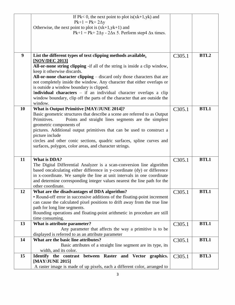
9 List the different types of text clipping methods available.
[NOV/DEC 2013]
All-or-none string clipping -if all of the string is inside a clip window,
keep it otherwise discards.
All-or-none character clipping – discard only those characters that are
not completely inside the window. Any character that either overlaps or
is outside a window boundary is clipped.
Individual characters – if an individual character overlaps a clip
window boundary, clip off the parts of the character that are outside the
window.
C305.1 BTL2
10 What is Output Primitive [MAY/JUNE 2014]?
Basic geometric structures that describe a scene are referred to as Output
Primitives. Points and straight lines segments are the simplest
geometric components of
pictures. Additional output primitives that can be used to construct a
picture include
circles and other conic sections, quadric surfaces, spline curves and
surfaces, polygon, color areas, and character strings.
C305.1 BTL1
11 What is DDA?
The Digital Differential Analyzer is a scan-conversion line algorithm
based oncalculating either difference in y-coordinate (dy) or difference
in x-coordinate. We sample the line at unit intervals in one coordinate
and determine corresponding integer values nearest the line path for the
other coordinate.
C305.1 BTL1
12 What are the disadvantages of DDA algorithm?
• Round-off error in successive additions of the floating-point increment
can cause the calculated pixel positions to drift away from the true line
path for long line segments.
Rounding operations and floating-point arithmetic in procedure are still
time consuming.
C305.1 BTL1
13 What is attribute parameter?
Any parameter that affects the way a primitive is to be
displayed is referred to as an attribute parameter
C305.1 BTL1
14 What are the basic line attributes?
Basic attributes of a straight line segment are its type, its
width, and its color.
C305.1 BTL1
15 Identify the contrast between Raster and Vector graphics.
[MAY/JUNE 2015]
A raster image is made of up pixels, each a different color, arranged to
C305.1 BTL3

4
display an image. A vector image is made up of paths, each with a
mathematical formula (vector) that tells the path how it is shaped and
what color it is bordered with or filled by.
The major difference is that raster image pixels do not retain their
appearance as size increases – when you blow a photograph up, it
becomes blurry for this reason. Vector images do retain appearance
regardless of size, since the mathematical formulas dictate how the
image is rendered
16 Compute the resolution of a 2*2 inch image that has 512 * 512
pixels. [NOV /DEC 2015]
The maximum number of points that can be displayed without an
overlap on a CRT is called as resolution. Measured by pixels per inch.
Resolution of the given image is 256 pixel.
C305.1 BTL2
17 Give the contents of the display file. [NOV /DEC 2015]
Display file contains function definitions of graphic primitives that are
updated as per the need to the application program and generated by
graphics software.
A display list (or display file) is a series of graphics commands that
define an output image. The image is created (rendered) by executing
the commands to combine various primitives.
This activity is most often performed by specialized display or
processing hardware partly or completely independent of the system's
CPU for the purpose of freeing the CPU from the overhead of
maintaining the display, and may provide output features or speed
beyond the CPU's capability.
C305.1 BTL1
18 Define Computer Graphics.
Computer graphics remains one of the most existing and rapidly
growing computer fields. Computer graphics may be defined as a
pictorial representation or graphical representation of objects in a
computer
C305.1 BTL1
19 What is meant by scan code?
When a key is pressed on the keyboard, the keyboard controller places
a code carry to the key pressed into a part of the memory called as the
keyboard buffer. This code is called as the scan code.
C305.1 BTL1
20 What is meant by refreshing of the screen?
Some method is needed for maintaining the picture on the screen.
Refreshing of screen is done by keeping the phosphorus glowing to
redraw the picture repeatedly. (i.e.) By quickly directing the electronic
beam back to the same points.
C305.1 BTL1
21 Define Random scan/Raster scan displays.
Random scan is a method in which the display is made by the
electronic beam which is directed only to the points or part of the
screen where the picture is to be drawn.
C305.1 BTL1

5
The Raster scan system is a scanning technique in which the electrons
sweep from top to bottom and from left to right. The intensity is
turned on or off to light and unlight the pixel.
22 List out the merits and demerits of Penetration techniques.
The merits and demerits of the Penetration techniques are as follows
• It is an inexpensive technique
• It has only four colors
• The quality of the picture is not good when it is compared to
other techniques
• It can display color scans in monitors
• Poor limitation etc.
C305.1 BTL1
23 List out the merits and demerits of DVST.
The merits and demerits of direct view storage tubes [DVST] are as
follows
• It has a flat screen
• Refreshing of screen is not required
• Selective or part erasing of screen is not possible
DEMERITS
• It has poor contrast
• Performance is inferior to the refresh CRT.
C305.1 BTL1
24 What do you mean by emissive and non-emissive displays?
The emissive display converts electrical energy into light energy. The
plasma panels, thin film electro- luminescent displays are the
examples.
The Non emissive are optical effects to convert the sunlight or light
from any other source to graphic form. Liquid crystal display is an
example.
C305.1 BTL1
26 What is persistence?
The time it takes the emitted light from the screen to decay one tenth
of its original intensity is called as persistence.
C305.1 BTL1
27 What is resolution? APRIL/MAY 2017
The maximum number of points that can be displayed without an
overlap on a CRT is called as resolution.
C305.1 BTL1
28 What is Aspect ratio?
The ratio of vertical points to the horizontal points necessary to
produce length of lines in both directions of the screen is called the
Aspect ratio. Usually the aspect ratio is ¾.
C305.1 BTL1
29 What is meant by Addressability?
The Addressability is the number of individual dots per inch (d.p.i)
that can be created. If the address of the current dot is (x, y) then the
next dot will be (x+y), (x+y+1) etc.
C305.1 BTL1
30 What is a dot size?
Dot size may be defined as the diameter of a single dot on the devices
output. Dot size is also called as the Spot size.
C305.1 BTL1
31 What is interdot distance?
Interdot distance is the reciprocal of addressability. If the
addressability is large, the interdot distance will be less. The interdot
distance should be less to get smooth shapes.
C305.1 BTL1
6
32 What is the difference between impact and non-impact printers?
Impact printer press formed character faces against an inked ribbon on
to the paper. A line printer and dot-matrix printer are examples.
Non-impact printer and plotters use Laser techniques, inkjet sprays,
Xerographic process, electrostatic methods and electro thermal
methods to get images onto the papers. Examples are: Inkjet/Laser
printers.
C305.1 BTL1
PART – B
S.NO QUESTIONS CO BLOOM’S
LEVEL
1 Write down and explain the midpoint circle drawing
algorithm. Assume 10 cm as the radius and co-ordinate origin
as the centre of the circle[NOV/DEC 2011, NOV/DEC
2014,MAY/JUNE 2014]. APRIL/MAY 2017
Refer page no. : 118-121
C305.1 BTL2
2 Explain about Bresenham’s circle generating algorithm
[MAY/JUNE 2012].
Refer page no. : 117-118
C305.1 BTL2
3 Explain the Bresenham’s Line drawing algorithm and trace the
algorithm for the given points(2,1)to (10,12).List the advantages
of Bresenham’s Line drawing algorithm over DDA algorithm.
[NOV/DEC 2012], NOV/DEC 2016
Refer page no. : 106-110
C305.1 BTL2
4 Explain the basic concept of Midpoint ellipse drawing
algorithm. Derive the decision parameter for the algorithm
and write down the algorithm steps. [MAY/JUNE
2013,MAY/JUNE 2014]
Refer Page No:122-124
C305.1 BTL2
5 Explain the basic concept of Midpoint ellipse drawing
algorithm. Derive the decision parameter for the algorithm
and write down the algorithm steps. [MAY/JUNE
2013,MAY/JUNE 2014]
Refer Page No:122-124
C305.1 BTL2
6 (i)Summarize Midpoint circle drawing procedure.
(ii)Use the above procedure to compute points on a circle with C305.1 BTL2

7
centre at (5,5) and radius of 8 units.
[MAY/JUNE 2015]
Refer Notes.
7 (i) Define and differentiate random scan and raster scan
devices. [NOV /DEC 2015] NOV /DEC 2016
(ii) Using Bresenhams circle drawing algorithm plot one
quadrant circle of radius 7 pixels with origin as centre. [NOV
/DEC 2015]
Refer Notes.
C305.1 BTL4
8 (i) How are event driven input devices handled by the
hardware? Explain. [NOV /DEC 2015]
(ii)Discuss the primitives used for filtering. [NOV /DEC 2015]
Refer Class notes
C305.1 BTL6
9 Explain the working principle of CRT with neat diagram.
NOV /DEC 2016
Refer page no :35-37
C305.1 BTL2
8
UNIT II
TWO DIMENSIONAL GRAPHICS
Two dimensional geometric transformations – Matrix representations and homogeneous
coordinates, composite transformations; Two dimensional viewing – viewing pipeline, viewing
coordinate reference frame; widow-to-viewport coordinate transformation, Two dimensional
viewing functions; clipping operations – point, line, and polygon clipping algorithms.
PART - A
S.NO QUESTIONS CO BLOOM’S
LEVEL
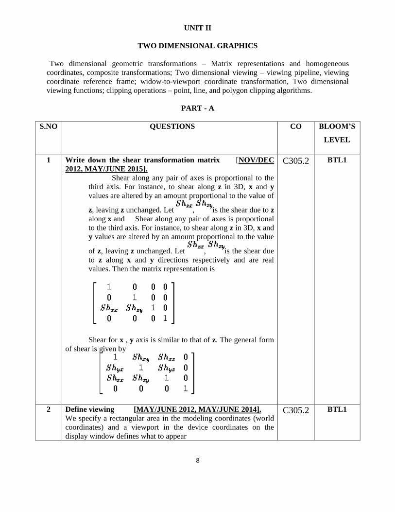
1 Write down the shear transformation matrix [NOV/DEC
2012, MAY/JUNE 2015].
Shear along any pair of axes is proportional to the
third axis. For instance, to shear along z in 3D, x and y
values are altered by an amount proportional to the value of
z, leaving z unchanged. Let , is the shear due to z
along x and Shear along any pair of axes is proportional
to the third axis. For instance, to shear along z in 3D, x and
y values are altered by an amount proportional to the value
of z, leaving z unchanged. Let , is the shear due
to z along x and y directions respectively and are real
values. Then the matrix representation is
Shear for x , y axis is similar to that of z. The general form
of shear is given by
C305.2 BTL1
2 Define viewing [MAY/JUNE 2012, MAY/JUNE 2014].
We specify a rectangular area in the modeling coordinates (world
coordinates) and a viewport in the device coordinates on the
display window defines what to appear
C305.2 BTL1
9
viewport defines where to display
3 Differentiate oblique and orthogonal projections
[NOV/DEC 2012]. APRIL/MAY2017
Oblique projection is a simple type of graphical projection used
for producing pictorial, two-dimensional images of three-
dimensional objects
Orthographic projection (or orthogonal projection) is a means
of representing a three-dimensional object in two dimensions. It is
a form of parallel projection, where the view direction is
orthogonal to the projection plane, resulting in every plane of the
scene appearing in affine transformation on the viewing surface. It
is further divided into multiview orthographic projections and
axonometric pictorials.
C305.2 BTL2
4 What is Critical Fusion Frequency?
[MAY/JUNE 2013]
The slowest refresh rate at which flicker disappears. Depends on
persistence, intensity, ambient lighting, phosphor color, and the
observer.
C305.2 BTL1
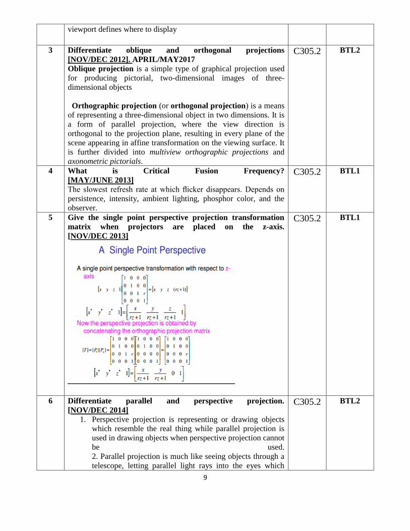
5 Give the single point perspective projection transformation
matrix when projectors are placed on the z-axis.
[NOV/DEC 2013]
C305.2 BTL1
6 Differentiate parallel and perspective projection.
[NOV/DEC 2014]
1. Perspective projection is representing or drawing objects
which resemble the real thing while parallel projection is
used in drawing objects when perspective projection cannot
be used.
2. Parallel projection is much like seeing objects through a
telescope, letting parallel light rays into the eyes which
C305.2 BTL2
10
produce visual representations without depth while
perspective projection represents objects in a three-
dimensional way.
3. In perspective projection, objects that are far away
appear smaller, and objects that are near appear bigger
while parallel projection does not create this effect.
4. While parallel projection may be best for architectural
drawings, in cases wherein measurements are necessary, it
is better to use perspective projection.
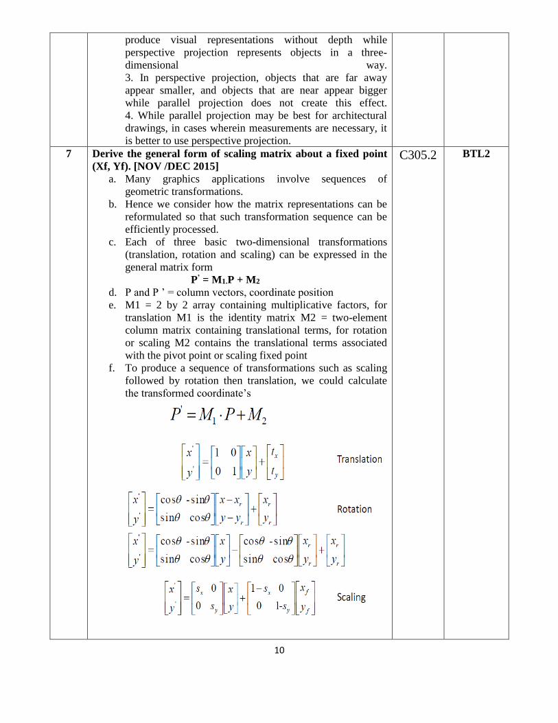
7 Derive the general form of scaling matrix about a fixed point
(Xf, Yf). [NOV /DEC 2015]
a. Many graphics applications involve sequences of
geometric transformations.
b. Hence we consider how the matrix representations can be
reformulated so that such transformation sequence can be
efficiently processed.
c. Each of three basic two-dimensional transformations
(translation, rotation and scaling) can be expressed in the
general matrix form
P’ = M1.P + M2
d. P and P ’ = column vectors, coordinate position
e. M1 = 2 by 2 array containing multiplicative factors, for
translation M1 is the identity matrix M2 = two-element
column matrix containing translational terms, for rotation
or scaling M2 contains the translational terms associated
with the pivot point or scaling fixed point
f. To produce a sequence of transformations such as scaling
followed by rotation then translation, we could calculate
the transformed coordinate’s
C305.2 BTL2
11
g. A more efficient approach is to combine the
transformations so that the final coordinate positions are
obtained directly from the initial coordinates, without
calculating intermediate coordinate values.
General Form Scaling matrix about a fixed point
Sx 0 0
0 Sy 0
xf(1-Sx) yf(1-Sy) 1
8 Write down the conditions for point clipping in window. [NOV
/DEC 2015]
Point Clipping:
1. Assuming that the clip window is a rectangle in
standard position
2. Saving a point P=(x, y) for display
xwmin <=x<=xwmax
ywmin <=y<=ywmax
3. Appling Fields - Particles (explosion, sea foam)
C305.2 BTL1
9 What is Transformation?
Transformation is the process of introducing changes in the
shape size and orientation of the object using scaling rotation
reflection shearing & translation etc.
C305.2 BTL1
10 Write short notes on active and passive transformations.
In the active transformation the points x and y represent
different coordinates of the same coordinate system. Here all the
points are acted upon by the same transformation and hence the
shape of the object is not distorted.
In a passive transformation the points x and y represent same
points in the space but in a different coordinate system. Here the
change in the coordinates is merely due to the change in the type
of the user coordinate system.
C305.2 BTL1
12 What is rotation?
A 2-D rotation is done by repositioning the coordinates along a
circular path, in X = rcos (q + f) and Y = r sin (q + f).
C305.2 BTL1
13 What is scaling?
The scaling transformations changes the shape of an object and
can be carried out by multiplying each vertex (x,y) by scaling
factor Sx,Sy where Sx is the scaling factor of x and Sy is the
scaling factor of y.
C305.2 BTL1
14 What is shearing?
The shearing transformation actually slants the object along the
X direction or the Y direction as required.ie; this transformation
slants the shape of an object along a required plane.
C305.2 BTL1
15 Distinguish between window port & view port?
A portion of a picture that is to be displayed by a window is
known as window port. The display area of the part selected or
C305.2 BTL2
12
the form in which the selected part is viewed is known as view
port.
16 Define clipping? And types of clipping.
Clipping is the method of cutting a graphics display to neatly fit a
predefined graphics region or the view port.
• Point clipping
• Line clipping
• Area clipping
• Curve clipping
• Text clipping
C305.2 BTL1
17 What is covering (exterior clipping)? APRIL/MAY2017
This is just opposite to clipping. This removes the lines coming
inside the windows and displays the remaining. Covering is
mainly used to make labels on the complex pictures.
C305.2 BTL1
18 What is the need of homogeneous coordinates?
To perform more than one transformation at a time, use
homogeneous coordinates or matrixes. They reduce unwanted
calculations intermediate steps saves time and memory and
produce a sequence of transformations
C305.2 BTL1
19 Distinguish between uniform scaling and differential scaling.
When the scaling factors sx and sy are assigned to the same value,
a uniform scaling is produced that maintains relative object
proportions. Unequal values for sx and sy result in a differential
scaling that is often used in design application
C305.2 BTL2
20 What is fixed point scaling?
The location of a scaled object can be controlled by a position
called the fixed point that is to remain unchanged after the scaling
transformation
C305.2 BTL1
21 Define Affine transformation.
A coordinate transformation of the form X= axxx +axyy+bx, y
‟ayxx+ayy y+by is called a two-dimensional affine
transformation. Each of the transformed coordinates x „and y „is
a linear function of the original coordinates x and y, and
parameters aij and bk are constants determined by the
transformation type.
C305.2 BTL1
22 Distinguish between bitBlt and pixBlt.
Raster functions that manipulate rectangular pixel arrays are
generally referred to as raster ops. Moving a block of pixels
from one location to another is also called a block transfer of
C305.2 BTL2
13
pixel values. On a bilevel system, this operation is called a bitBlt
(bit-block transfer), on multilevel system t is called pixBlt.
23 List out the various Text clipping.
• All-or-none string clipping -if all of the string is inside a
clip window, keep it otherwise discards.
• All-or-none character clipping – discard only those
characters that are not completely inside the window.
Any character that either overlaps or is outside a window
boundary is clipped.
• Individual characters – if an individual character
overlaps a clip window boundary, clip off the parts of the
character that are outside the window.
C305.2 BTL1
24 What is fixed point scaling?
The location of a scaled object can be controlled by a
position called the fixed point that is to remain unchanged
after the scaling transformation
C305.2 BTL1
25 List out the various Text clipping.
• All-or-none string clipping - if all of the string is inside a
clip window, keep it otherwise discards.
• All-or-none character clipping – discard only those
characters that are not completely inside the window.
Any character that either overlaps or is outside a
window boundary is clipped.
• Individual characters – if an individual character
overlaps a clip window boundary, clip off the parts of
the character that are outside the window.
C305.2 BTL1
26 Write down the shear transformation matrix. (nov/dec 2012)
A transformation that distorts the shape of an object
such that the transformed shape appears as if the object were
composed of internal layers that had been caused to slide over
each other is called a shear.
C305.2 BTL1
27 What is the use of clipping?(may/june 2012)
Clipping in computer graphics is to remove objects, lines or line
segments that are outside the viewing volume.
C305.2 BTL1
28 How will you clip a point?(may/june 2013)
Assuming that the clip window is a rectangle in standard
position, we save a point P=(x,y) for display if the following
inequalities are satisfied:
xwmin ≤ x≤ xwmax ywmin ≤ y≤
ywmax
C305.2 BTL1

14
where the edges of the clip window (xwmin ,xwmax, ywmin,
ywmax) can be either the world-coordinate window boundaries
or viewport boundaries. If any one of these inequalities is not
satisfied, the points are clipped (not saved for display).
29 Define viewing transformation.
The mapping of a part of world coordinate scene to device
coordinates are called viewing transformation. Two
dimensional viewing transformations is simply referred to
as window to viewport transformation or the windowing
transformation.
C305.2 BTL1
30. Brief on window to viewpoint coordinate transformation. NOV
/DEC 2016, APRIL/MAY2017
Window-to-Viewport mapping is the process of mapping or
transforming a two-dimensional, world-coordinate scene to device
coordinates. In particular, objects inside the world or clipping
window are mapped to the viewport. The viewport is displayed in
the interface window on the screen. In other words, the clipping
window is used to select the part of the scene that is to be
displayed. The viewport then positions the scene on the output
device.
C305.2 BTL1
PART - B
S.NO QUESTIONS CO BLOOM’S
LEVEL
1 i)Explain two dimenstional translation and scaling with an
example.
ii)Obtain a transformation matrix for rotating an object and
scaling about a specified the pivot point. [MAY/JUNE
2013] NOV /DEC 2016 APRIL/MAY 2017
Refer Notes.
C305.2 BTL2
2 Differentiate parallel and perspective projections and derive
their projection matrices.
[NOV/DEC 2011,MAY/JUNE 2014].
Refer page no. : 459-466
C305.2 BTL4
3 Differentiate parallel and perspective projections 8 mark
[NOV/DEC 2012].
Refer page no. : 459-466
C305.2 BTL4
15
4 (i) Flip the given quadrilateral A(10,8) , B (22,8) , C (34,17) ,
D(10,27) about the origin and then zoom it to twice its size. Find
the new positions of the quadrilateral [NOV /DEC 2015]
(ii)Derive the viewing pipeline and transformation matrix
[NOV /DEC 2015] NOV /DEC 2016
Refer Notes.
C305.2 BTL2
5 (i) Clip the given line A(1,3), B(4,1) against a window P(2,2),
Q(5,2), R(5,4), S(2,4) using Liang Barsky line clipping algorithm
[NOV /DEC 2015]
(ii)Explain two dimensional viewing pipeline in detail [NOV
/DEC 2015] APRIL/MAY 2017
Refer Notes.
C305.2 BTL2
6 Explain in detail the Cohen-Sutherland line clipping algorithm
with an example [NOV/DEC 2011, MAY/JUNE
2012,MAY/JUNE 2014, NOV/DEC 2014].
Refer page no. : 246-248
C305.2 BTL2
7 The reflection along the line y = x is equivalent to the reflection
along the X axis followed by counter clockwise rotation by O
degrees. Find the value of Theta. [NOV/DEC 2013]
Refer Notes
C305.2 BTL2
8 (i)Rotate a triangle [(4,6),(2,2),(6,2)] about the vertex (4,6) by
180o CCW and find the new vertices
(ii)Prove that Reflection is equal to Rotation by 180o.
[MAY/JUNE 2015]
Refer Notes.
C305.2 BTL2
9 With suitable examples, explain the following
(i)Two successive Rotation ,translation and scaling
transformation
Refer page no. : 206-208 NOV /DEC 2016
(ii)curve clipping algorithm. [NOV/DEC 2012].
Refer page no. : 264
C305.2 BTL2
10 Explain in detail the Sutherland Hodgeman polygon clipping
algorithm with an example 8 Mark [NOV/DEC
2016].
Refer page no :225-226
C305.2 BTL2
UNIT III
THREE DIMENSIONAL GRAPHICS
Three dimensional concepts; Three dimensional object representations – Polygon surfaces-
Polygon tables- Plane equations - Polygon meshes; Curved Lines and surfaces, Quadratic
surfaces; Blobby objects; Spline representations – Bezier curves and surfaces -B-Spline curves
and surfaces.

16
TRANSFORMATION AND VIEWING: Three dimensional geometric and modeling
transformations – Translation, Rotation, Scaling, composite transformations; Three dimensional
viewing – viewing pipeline, viewing coordinates, Projections, Clipping; Visible surface detection
methods.
PART - A
S.NO QUESTIONS CO BLOOM’S
LEVEL
1 Give the general expression of Bezier Bernstein polynomial.
[NOV/DEC 2013]
The n + 1 Bernstein basis polynomials of degree n are
defined as
Where is a binomial coefficient.
The Bernstein basis polynomials of degree n form a basis for
the vector space Πn of polynomials of degree at most n.
A linear combination of Bernstein basis polynomials
is called a Bernstein polynomial or polynomial in Bernstein
form of degree n. The coefficients are called Bernstein
coefficients or Bézier coefficients.
C305.3 BTL1
2 What are the advantages of B spline over Bezier curve?
[MAY/JUNE 2013]
B-spline curves require more information (i.e., the degree of the curve and
a knot vector) and a more complex theory than Bézier curves. But, it has
more advantages to offset this shortcoming. First, a B-spline curve can be
a Bézier curve.
Second, B-spline curves satisfy all important properties that Bézier curves
have. Third, B-spline curves provide more control flexibility than Bézier
curves can do. For example, the degree of a B-spline curve is separated
from the number of control points. More precisely, we can use lower
degree curves and still maintain a large number of control points. We can
change the position of a control point without globally changing the shape
of the whole curve (local modification property). Since B-spline curves
satisfy the strong convex hull property, they have a finer shape control.
Moreover, there are other techniques for designing and editing the shape
of a curve such as changing knots.
C305.3 BTL1
3 What are spline curves? [NOV/DEC 2011, NOV/DEC 2012,
NOV/DEC 2014, MAY/JUNE 2014].
A spline curve is a flexible strip used to produce a smooth curve through a
C305.3 BTL1
17
designated set of points. The spline curve refers to any section curve
formed with polynomial sections satisfying specified conditions at the
boundary of the pieces
4 Define quadric surfaces. [NOV/DEC 2011].
Surfaces described with second degree equations are known as quadric
surfaces. They include spheres, ellipsoids, tori, parabolids and
hyperbolids.
C305.3 BTL1
5 Differentiate parallel projection from perspective projection
[MAY/JUNE 2012].
Perspective projection is defined by straight rays of projection drawn from
object to the centre of projection and image is drawn where these rays
untersect with the viewplane...while parallel projection is defined by
parallel lines drawn from object in fixed direction towards the viewplane
In perspective projection centre of projection is at finite distance from
viewplane and in parallel projection centre of projection lies at infinite
distance.
Prespective projection form realistic picture of object but parallel
projection do not form realistic view of object.
C305.3 BTL2
6 What is Mesh Modeling ?
[MAY/JUNE 2015]
A polygon mesh is a collection of vertices, edges and faces
that defines the shape of a polyhedral object in 3D computer
graphics and solid modeling. The faces usually consist
of triangles (triangle mesh), quadrilaterals, or other simple convex
polygons, since this simplifies rendering, but may also be
composed of more general concave polygons, or polygons with
holes.
C305.3 BTL1
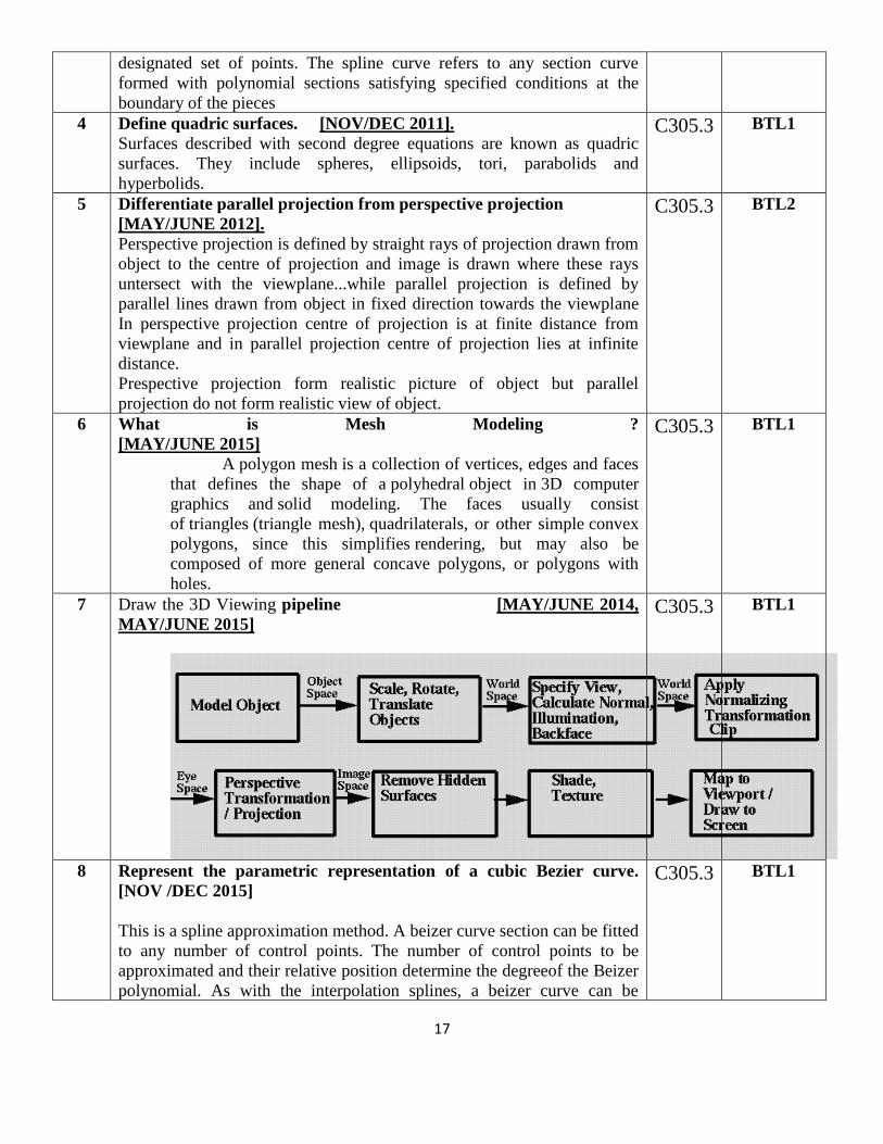
7 Draw the 3D Viewing pipeline [MAY/JUNE 2014,
MAY/JUNE 2015]
C305.3 BTL1
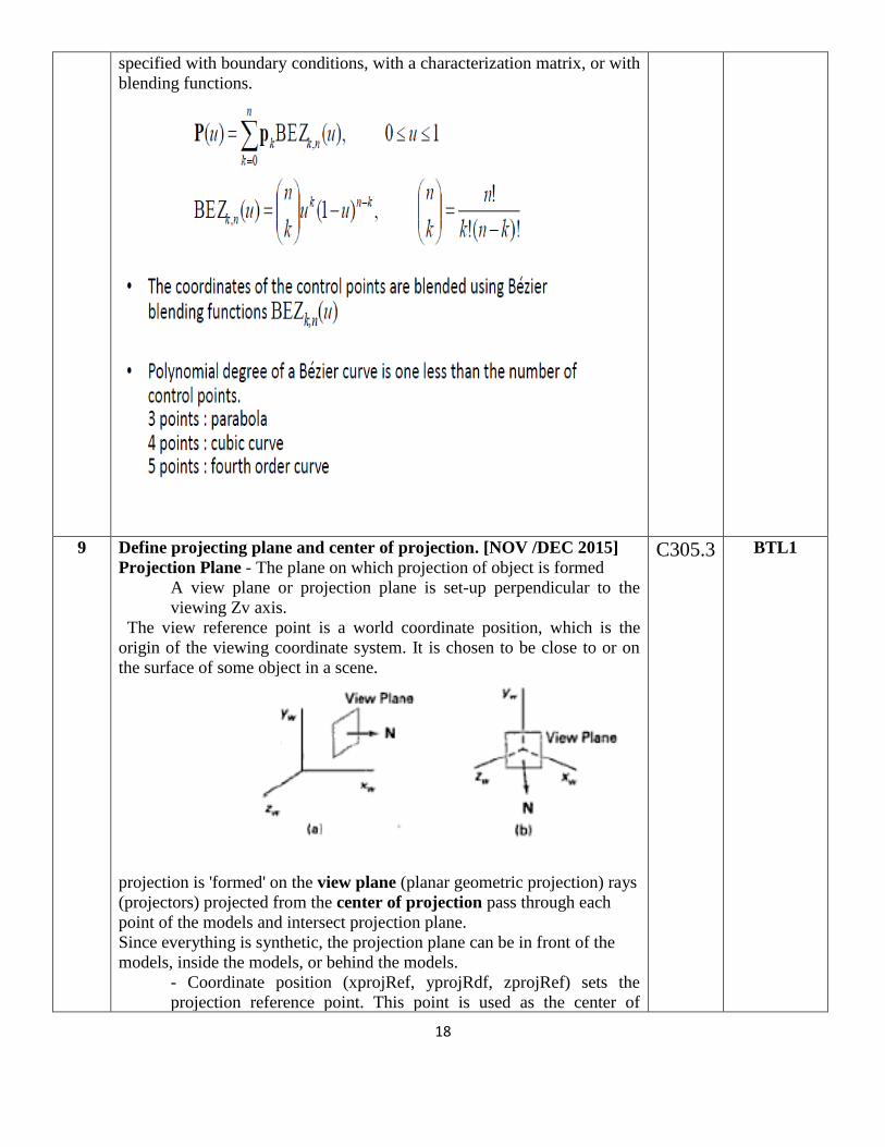
8 Represent the parametric representation of a cubic Bezier curve.
[NOV /DEC 2015]
This is a spline approximation method. A beizer curve section can be fitted
to any number of control points. The number of control points to be
approximated and their relative position determine the degreeof the Beizer
polynomial. As with the interpolation splines, a beizer curve can be
C305.3 BTL1
18
specified with boundary conditions, with a characterization matrix, or with
blending functions.
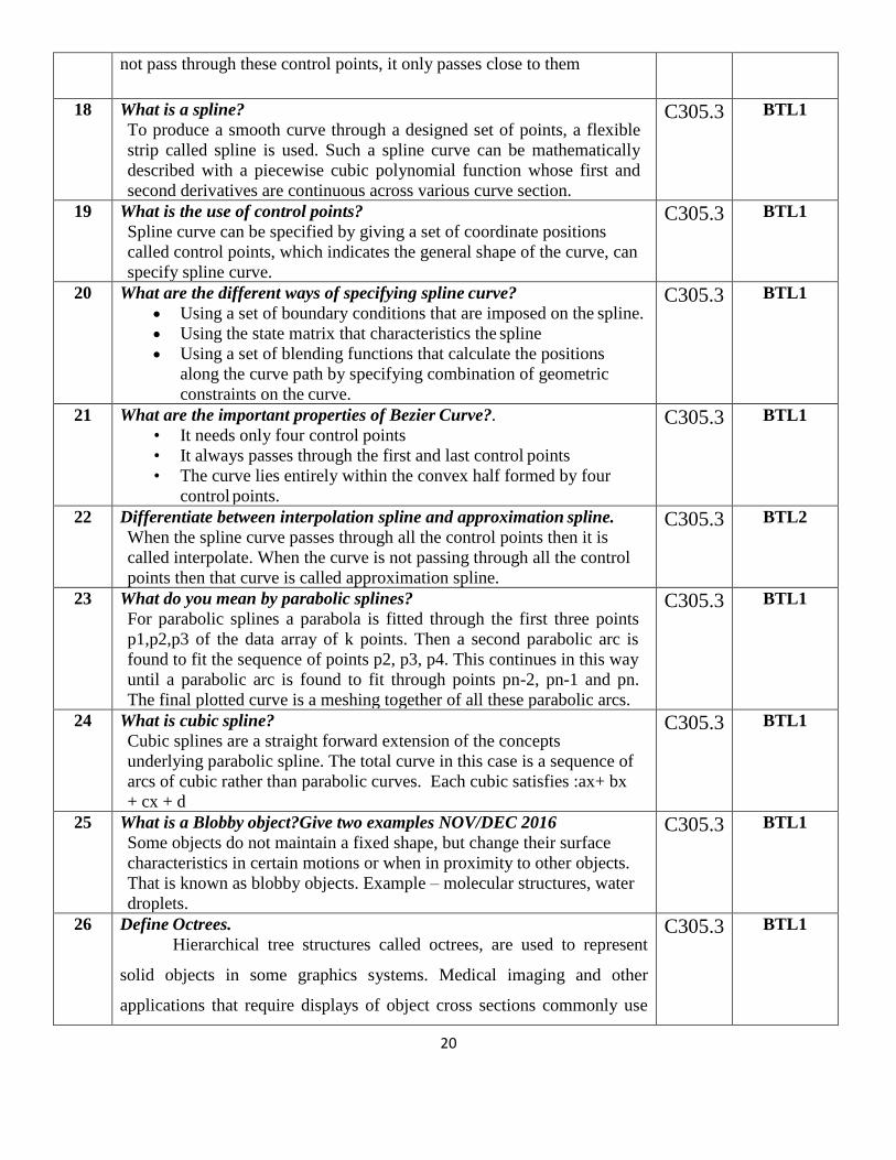
9 Define projecting plane and center of projection. [NOV /DEC 2015]
Projection Plane - The plane on which projection of object is formed
A view plane or projection plane is set-up perpendicular to the
viewing Zv axis.
The view reference point is a world coordinate position, which is the
origin of the viewing coordinate system. It is chosen to be close to or on
the surface of some object in a scene.
projection is 'formed' on the view plane (planar geometric projection) rays
(projectors) projected from the center of projection pass through each
point of the models and intersect projection plane.
Since everything is synthetic, the projection plane can be in front of the
models, inside the models, or behind the models.
- Coordinate position (xprojRef, yprojRdf, zprojRef) sets the
projection reference point. This point is used as the center of
C305.3 BTL1

19
projection if projType is set to perspective; otherwise, this point
and the center of the viewplane window define the parallel
projection vector.
10 What are the various representation schemes used in three
dimensional objects?
• Boundary representation (B-res) – describe the 3 dimensional
object as a set of surfaces that separate the object interior from
the environment.
• Space-portioning representation – describe interior properties, by
partitioning the spatial region containing an object into a set of
small, no overlapping, contiguous solids.
C305.3 BTL1
11 What is Polygon mesh?
Polygon mesh is a method to represent the polygon, when the object
surfaces are tiled, it is more convenient to specify the surface facets
with a mesh function. The various meshes are
• Triangle strip – (n-2) connected triangles
• Quadrilateral mesh – generates (n-1)(m-1) Quadrilateral
C305.3 BTL1
12 What is Bezier Basis Function?
Bezier Basis functions are a set of polynomials, which can be used
instead of the primitive polynomial basis, and have some useful
properties for interactive curve design.
C305.3 BTL1
13 What is surface patch?
A single surface element can be defined as the surface traced out as two
parameters (u, v) take all possible values between 0 and 1 in a two-
parameter representation. Such a single surface element is known as a
surface patch.
C305.3 BTL1
14 Write short notes on rendering bi-cubic surface patches of constant u
and v method.
The simple way is to draw the iso-parmetric lines of the surface.
Discrete approximations to curves on the surface are produced by
holding one parameter constant and allowing the other to vary at
discrete intervals over its whole range. This produce curves of constant
u and constant v.
C305.3 BTL1
15 What are the advantages of rendering polygons by scan line method?
i. The max and min values of the scan were easily found.
ii. The intersection of scan lines with edges is easily calculated by a
simple incremental method.
iii. The depth of the polygon at each pixel is easily calculated by an
incremental method.
C305.3 BTL1
16 What are the advantages of rendering by patch splitting?
• It is fast-especially on workstations with a hardware polygon-
rendering pipeline.
• It‟s speed can be varied by altering the depth of sub-division.
C305.3 BTL1
17 Define B-Spline curve.
A B-Spline curve is a set of piecewise(usually cubic) polynomial
segments that pass close to a set of control points. However the curve does
C305.3 BTL1
20
not pass through these control points, it only passes close to them
18 What is a spline?
To produce a smooth curve through a designed set of points, a flexible
strip called spline is used. Such a spline curve can be mathematically
described with a piecewise cubic polynomial function whose first and
second derivatives are continuous across various curve section.
C305.3 BTL1
19 What is the use of control points?
Spline curve can be specified by giving a set of coordinate positions
called control points, which indicates the general shape of the curve, can
specify spline curve.
C305.3 BTL1
20 What are the different ways of specifying spline curve?
• Using a set of boundary conditions that are imposed on the spline.
• Using the state matrix that characteristics the spline
• Using a set of blending functions that calculate the positions
along the curve path by specifying combination of geometric
constraints on the curve.
C305.3 BTL1
21 What are the important properties of Bezier Curve?.
• It needs only four control points
• It always passes through the first and last control points
• The curve lies entirely within the convex half formed by four
control points.
C305.3 BTL1
22 Differentiate between interpolation spline and approximation spline.
When the spline curve passes through all the control points then it is
called interpolate. When the curve is not passing through all the control
points then that curve is called approximation spline.
C305.3 BTL2
23 What do you mean by parabolic splines?
For parabolic splines a parabola is fitted through the first three points
p1,p2,p3 of the data array of k points. Then a second parabolic arc is
found to fit the sequence of points p2, p3, p4. This continues in this way
until a parabolic arc is found to fit through points pn-2, pn-1 and pn.
The final plotted curve is a meshing together of all these parabolic arcs.
C305.3 BTL1
24 What is cubic spline?
Cubic splines are a straight forward extension of the concepts
underlying parabolic spline. The total curve in this case is a sequence of
arcs of cubic rather than parabolic curves. Each cubic satisfies :ax+ bx
+ cx + d
C305.3 BTL1
25 What is a Blobby object?Give two examples NOV/DEC 2016
Some objects do not maintain a fixed shape, but change their surface
characteristics in certain motions or when in proximity to other objects.
That is known as blobby objects. Example – molecular structures, water
droplets.
C305.3 BTL1
26 Define Octrees.
Hierarchical tree structures called octrees, are used to represent
solid objects in some graphics systems. Medical imaging and other
applications that require displays of object cross sections commonly use
C305.3 BTL1

21
octree representation
27 Define Projection.
The process of displaying 3D into a 2D display unit is known as
projection. The projection transforms 3D objects into a 2D projection
plane. The process of converting the description of objects from world
coordinates to viewing coordinates is known as projection
C305.3 BTL1
28 What are the steps involved in 3D transformation?
• Modeling Transformation
• Viewing Transformation
• Projection Transformation
• Workstation Transformation
C305.3 BTL1
29 What do you mean by view plane?
A view plane is nothing but the film plane in camera which is positioned
and oriented for a particular shot of the scene.
C305.3 BTL1
30 What is view-plane normal vector?
This normal vector is the direction perpendicular to the view plane and it
is called as [DXN DYN DZN
C305.3 BTL1
31 What is view distance?
The view plane normal vector is a directed line segment from the view
plane to the view reference point. The length of this directed line
segment is referred to as view distance.
C305.3 BTL1
PART – B
S.NO QUESTIONS CO BLOOM’S
LEVEL
1 (a) (i) A cube has. its vertices located at A(0, 0, 10), B(10, 0,10),
C(10, 10, 10), D (0, 10,10), E(0, 0, 0), F(10, 0, 0), G(10, 10, 0),
11(0, 10, 0). The Y axis is vertical and Z axis is oriented towards
the viewer. The cube is being viewed from point (0,
20.80).Calculate the perspective view of the cube on XY plane.
(ii) Discuss on the various visualization techniques in detail.
[NOV/DEC 2013]
ReferNotes
C305.3 BTL2
22
2 (i) Calculate the new coordinates of a block rotated about x axis
by an angle of = 30 degrees. The original coordinates of the
block are given relative to the global xyz axis system. A(1, 1, 2)
B(2, I, 2) C(2, 2, 2) D(1, 2, 2) E(1, 1, 1) F(2, 1, 1) G(2, 2,1) 11(1, 2,
1).
(ii) Discuss on Area subdivision method of hidden surface
identification
algorithm.
[NOV/DEC 2013]
Refer Notes
C305.3 BTL2
3 (i)With suitable examples, explain the 3D transformations.
Refer page no. : 428-443 [NOV/DEC 2011,
MAY/JUNE 2012,MAY/JUNE 2014, MAY/JUNE 2015]
(ii)Write notes on quadric surfaces NOV/DEC 2012].
NOV/DEC 2016 APRIL/MAY 2017
Refer page no. : 330-335
C305.3 BTL2
4 i) Determine the blending function for uniform periodic Bspline
curve for n=4,d = 4. [MAY/JUNE 2013]
ii)Explain any one visible surface identification algorithm.
[MAY/JUNE 2013,MAY/JUNE 2014]
Refer Notes
C305.3 BTL2
5 With suitable examples, explain all 3D transformations.
[NOV/DEC 2011, MAY/JUNE 2012].
Refer page no. : 428-443
C305.3 BTL2
6 Explain about 3D object representations. [MAY/JUNE
2012 NOV/DEC 2014 ].
Refer page no. : 325-340
C305.3 BTL2
7 Discuss the visible surface detection methods in detail ?
[NOV/DEC 2014,MAY/JUNE 2015]
Refer page no. : 490-498
C305.3 BTL6
8 Discuss parallel projection and perspective projection in detail.
[MAY/JUNE 2014,MAY/JUNE 2015]. NOV/DEC 2016
Refer Notes
C305.3 BTL6
9 (i)Derive the parametric equation for a cubic Bezier curve
[NOV /DEC 2015] APRIL/MAY 2017
(ii)Compare and contrast orthographic, Axonometric and
Oblique projections [NOV /DEC 2015]
Refer Notes.
C305.3 BTL2
10 (i)Write down the Back face detection algorithm [NOV /DEC
2015]
(ii)How will you perform three dimensional rotation about any
C305.3 BTL2
23
arbitrary axis , arbitrary plane? [NOV /DEC 2015] NOV /DEC
2016]
Refer Notes.
11 Write notes on viewing coordinates 8 mark
[NOV/DEC 2016].
Refer page no. : 452-458
C305.3 BTL2
12 Write notes on viewing coordinates 8 mark
[NOV/DEC 2016].
Refer page no. : 452-458
C305.3 BTL2
13 i.A polygon has four vertices located at A(20, 10) B(60, 10) C(60,
30) D(20, 30). Calculate the vertices after applying a
transformation matrix to double the size of polygon with point
A located on the same place. (8) [NOV/DEC 2013]
ii.Brief on polygon meshes NOV /DEC 2016.
Refer Notes.
C305.3 BTL2
14 Discuss about 3Dimentional display methods. NOV/DEC2016
Refer page no. : 428-443
C305.3 BTL6
UNIT IV
ILLUMINATION AND COLOUR MODELS
Light sources - basic illumination models – halftone patterns and dithering techniques;
Properties of light - Standard primaries and chromaticity diagram; Intuitive colour concepts -
RGB colour model -YIQ colour model - CMY colour model - HSV colour model - HLS
colour model; Colour selection
PART – A
S.NO QUESTIONS CO BLOOM’S
LEVEL
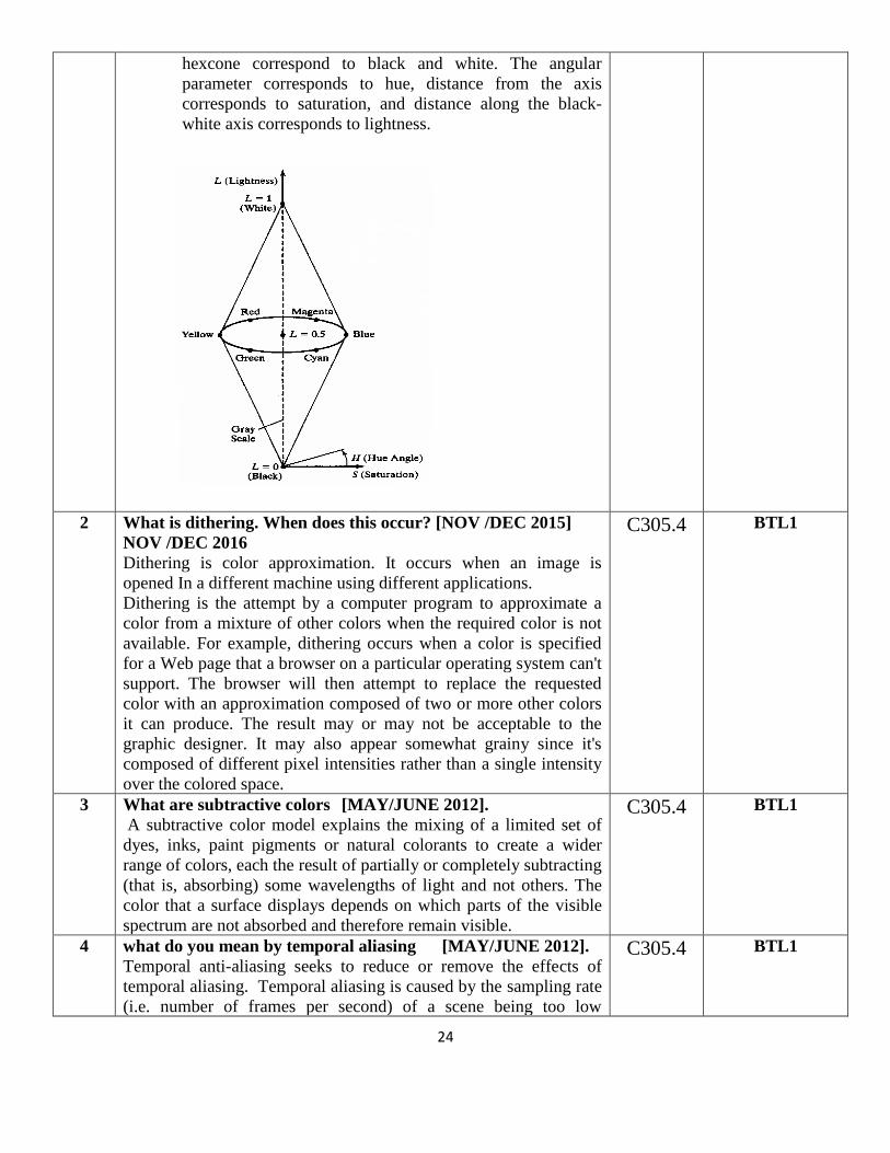
1 Draw the Color Model HLS double cone.
[MAY/JUNE 2013]
The HLS color space, also called HSL, stands for
"Hue, Saturation, Lightness." While the HSV (Hue
Saturation Value) can be viewed graphically as a
color cone or hexcone, HSL is drawn as a double cone or
double hexcone. Both systems are deformed versions of
the RGB colour cube. The two apexes of the HLS double
C305.4 BTL1
24
hexcone correspond to black and white. The angular
parameter corresponds to hue, distance from the axis
corresponds to saturation, and distance along the black-
white axis corresponds to lightness.
2 What is dithering. When does this occur? [NOV /DEC 2015]
NOV /DEC 2016
Dithering is color approximation. It occurs when an image is
opened In a different machine using different applications.
Dithering is the attempt by a computer program to approximate a
color from a mixture of other colors when the required color is not
available. For example, dithering occurs when a color is specified
for a Web page that a browser on a particular operating system can't
support. The browser will then attempt to replace the requested
color with an approximation composed of two or more other colors
it can produce. The result may or may not be acceptable to the
graphic designer. It may also appear somewhat grainy since it's
composed of different pixel intensities rather than a single intensity
over the colored space.
C305.4 BTL1
3 What are subtractive colors [MAY/JUNE 2012].
A subtractive color model explains the mixing of a limited set of
dyes, inks, paint pigments or natural colorants to create a wider
range of colors, each the result of partially or completely subtracting
(that is, absorbing) some wavelengths of light and not others. The
color that a surface displays depends on which parts of the visible
spectrum are not absorbed and therefore remain visible.
C305.4 BTL1
4 what do you mean by temporal aliasing [MAY/JUNE 2012].
Temporal anti-aliasing seeks to reduce or remove the effects of
temporal aliasing. Temporal aliasing is caused by the sampling rate
(i.e. number of frames per second) of a scene being too low
C305.4 BTL1
25
compared to the transformation speed of objects inside of the scene;
this causes objects to appear to jump or appear at a location instead
of giving the impression of smoothly moving towards them. To
avoid aliasing artifacts altogether, the sampling rate of a scene must
be at least twice as high as the fastest moving object.
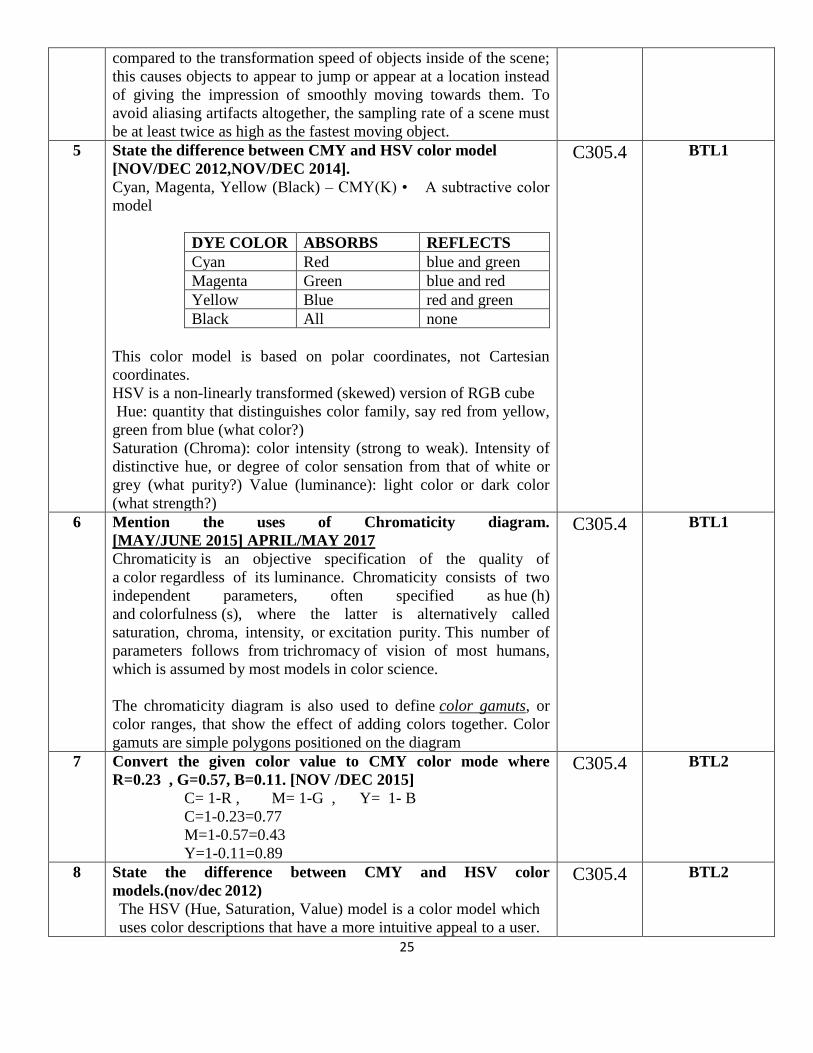
5 State the difference between CMY and HSV color model
[NOV/DEC 2012,NOV/DEC 2014].
Cyan, Magenta, Yellow (Black) – CMY(K) • A subtractive color
model
DYE COLOR ABSORBS REFLECTS
Cyan Red blue and green
Magenta Green blue and red
Yellow Blue red and green
Black All none
This color model is based on polar coordinates, not Cartesian
coordinates.
HSV is a non-linearly transformed (skewed) version of RGB cube
Hue: quantity that distinguishes color family, say red from yellow,
green from blue (what color?)
Saturation (Chroma): color intensity (strong to weak). Intensity of
distinctive hue, or degree of color sensation from that of white or
grey (what purity?) Value (luminance): light color or dark color
(what strength?)
C305.4 BTL1
6 Mention the uses of Chromaticity diagram.
[MAY/JUNE 2015] APRIL/MAY 2017
Chromaticity is an objective specification of the quality of
a color regardless of its luminance. Chromaticity consists of two
independent parameters, often specified as hue (h)
and colorfulness (s), where the latter is alternatively called
saturation, chroma, intensity, or excitation purity. This number of
parameters follows from trichromacy of vision of most humans,
which is assumed by most models in color science.
The chromaticity diagram is also used to define color gamuts, or
color ranges, that show the effect of adding colors together. Color
gamuts are simple polygons positioned on the diagram
C305.4 BTL1
7 Convert the given color value to CMY color mode where
R=0.23 , G=0.57, B=0.11. [NOV /DEC 2015]
C= 1-R , M= 1-G , Y= 1- B
C=1-0.23=0.77
M=1-0.57=0.43
Y=1-0.11=0.89
C305.4 BTL2
8 State the difference between CMY and HSV color
models.(nov/dec 2012)
The HSV (Hue, Saturation, Value) model is a color model which
uses color descriptions that have a more intuitive appeal to a user.
C305.4 BTL2
26
To give a color specification, a user selects a spectral color and
the amounts of white and black that is to be added to obtain
different shades, tint, and tones.
A color model defined with the primary colors cyan, magenta,
and yellow is useful for describing color output to hard-copy
devices.
9 What are subtractive colors?(may/june 2012)
RGB model is an additive system, the Cyan-Magenta-Yellow
(CMY) model is a subtractive color model. In a subtractive
model, the more that an element is added, the more that it
subtracts from white. So, if none of these are present the result is
white, and when all are fully present the result is black.
C305.4 BTL1
10 Define YIQ color model
In the YIQ color model, luminance (brightness) information in
contained in the Y parameter, chromaticity information (hue
and purity) is contained into the I and Q parameters.
A combination of red, green and blue intensities are chosen for
the Y parameter to yield the standard luminosity curve. Since Y
contains the luminance information, black and white TV monitors
use only the Y signal.
C305.4 BTL1
11 What do you mean by shading of objects?(nov/dec 2011)
A shading model dictates how light is scattered or reflected from
a surface. The shading models described here focuses on
achromatic light. Achromatic light has brightness and no color;
it is a shade of gray so it is described by a single value its
intensity.
A shading model uses two types of light source to illuminate the
objects in a scene : point light sources and ambient light.
C305.4 BTL1
12 What is texture?( nov/dec 2011)
The realism of an image is greatly enhanced by adding surface
texture to various faces of a mesh object. The basic technique
begins with some texture function, texture(s,t) in texture space ,
which has two parameters s and t. The function texture(s,t)
produces a color or intensity value for each value of s and t
between 0(dark)and 1(light).
C305.4 BTL1
13 What are the types of reflection of incident light?(nov/dec 2013)
There are two different types of reflection of incident light
Diffuse scattering.
Specular reflections.
C305.4 BTL1
14 Define rendering (may/june 2013)
Rendering is the process of generating an image from a
model (or models in what collectively could be called a scenefile),
by means of computer programs. Also, the results of such a model
can be called a rendering
C305.4 BTL1
27
15 Differentiate flat and smooth shading (may/june 2013)
The main distinction is between a shading method that
accentuates the individual polygons (flat shading) and a
method that blends the faces to de-emphasize the edges
between them (smooth shading).
C305.4 BTL2
16 Define shading (may/june 2012)
Shading is a process used in drawing for depicting levels of
darkness on paper by applying media more densely or with a
darker shade for darker areas, and less densely or with a lighter
shade for lighter areas.
C305.4 BTL1
17 What is a shadow? (nov/dec 2012)
Shadows make an image more realistic. The way one object casts a
shadow on another object gives important visual clues as to how
the two objects are positioned with respect to each other. Shadows
conveys lot of information as such, you are getting a second look at
the object from the view point of the light source
C305.4 BTL1
18 What are two methods for computing shadows?
Shadows as Texture.
Creating shadows with the use of a shadow buffer.
C305.4 BTL1
19 Write any two Drawbacks of Phong Shading
Relatively slow in speed.
More computation is required per pixel.
C305.4 BTL1
20 What are the two common sources of textures?
Bitmap Textures.
Procedural Textures.
C305.4 BTL1
21 Write two types of smooth shading.
Gouraud shading.
Phong shading.
C305.4 BTL1
22 What is a color model?
A color model is a method for explaining the properties or
behavior of color within some particular context. Example:
XYZ model, RGB model.
C305.4 BTL1
23 Define intensity of light.
Intensity is the radiant energy emitted per unit time, per unit solid
angle, and per unit projected area of source.
C305.4 BTL1
24 What is hue?
The perceived light has a dominant frequency (or dominant
wavelength). The dominant frequency is also called as hue or
simply as color.
C305.4 BTL1
25 What is purity of light?
Purity describes how washed out or how “pure” the c olor of the
light appears. pastels and pale colors are described as less pure
C305.4 BTL1
28
26 Define the term chromacity.
The term chromacity is used to refer collectively to the two
properties describing color characteristics: purity and dominant
frequency
C305.4 BTL1
27 How is the color of an object determined?
When white light is incident upon an object, some frequencies are
reflected and some are absorbed by the object. The combination of
frequencies present in the reflected light determines what we
perceive as the color of the object
C305.4 BTL1
28 Define purity or saturation.
Purity describes how washed out or how "pure" the color of
the light appears
C305.4 BTL1
29 Define complementary colors.
If the two color sources combine to produce white light, they are
referred to as 'complementary colors. Examples of
complementary color pairs are red and cyan, green and magenta,
and blue and yellow.
C305.4 BTL1
30 Define primary colors.
The two or three colors used to produce other colors in a color
model are referred to as primary colors.
C305.4 BTL1
31 State the use of chromaticity diagram.
Comparing color gamuts for different sets of
primaries.Identifying complementary colors. Determining
dominant wavelength and purity of a given color.
C305.4 BTL1
32 What is Color Look up table?
In color displays, 24 bits per pixel are commonly used, where 8 bits
represent 256 level for each color. It is necessary to read 24- bit for
each pixel from frame buffer. This is very time consuming. To
avoid this video controller uses look up table to store many entries
to pixel values in RGB format. This look up table is commonly
known as colour table
C305.4 BTL1
PART - B

29
S.NO QUESTIONS CO BLOOM’S
LEVEL
1 Briefly explain different color models in detail.
[MAY/JUNE 2013, MAY/JUNE 2014, MAY/JUNE 2015]
APRIL/MAY 2017
Refer page no. : 592, 595-597
C305.4 BTL2
2 Discuss on the various colour models in detail.
[NOV/DEC2013]
Refer page no. : 592, 595-597
C305.4 BTL2
3 Write notes on YIQ and HSV color model. [NOV/DEC 2016].
Refer page no. : 592, 595-597
C305.4 BTL1
4 Compare and contrast between RGB and CMY color models
[MAY/JUNE 2012].
Refer page no. : 592,595
C305.4 BTL4
5 Explain RGB color model in detail [NOV/DEC 2014].
[NOV/DEC 2016].
Refer page no. : 592-593
C305.4 BTL2
6 Discuss the color spectrum, color concepts and color models in
detail. [NOV /DEC 2015]
Refer page no. : 592, 595-597
C305.4 BTL6
7 Explain the illumination models in detail [NOV /DEC 2015]
Refer page no. : 495-497
C305.4 BTL2
8 Explain about Halftone approximation and Dithering techniques in
detail.NOV/DEC 2016 APRIL/MAY 2017
Refer page no. : 610-613
C305.4 BTL2

30
UNIT V
ANIMATIONS & REALISM
ANIMATION GRAPHICS: Design of Animation sequences – animation function – raster
animation –key frame systems – motion specification –morphing – tweening.
COMPUTER GRAPHICS REALISM: Tiling the plane – Recursively defined curves – Koch
curves – C curves – Dragons –space filling curves – fractals – Grammar based models – fractals
– turtle graphics – ray tracing.
PART - A
S.NO QUESTIONS CO BLOOM’S LEVEL
1 What are keyframe systems [NOV/DEC 2012].
Keyframe systems are specialized animation languages designed
simply to generate the in-betweensfrom the user specified
keyframes.
C305.5 BTL1
2 What is animation? [NOV/DEC 2011]. / Give the basic principle
of animation [NOV /DEC 2015]
Computer animation refers to any time sequence of visual changes
in a scene. Computer animations can be generated by changing
camera parameters such as position, orientation and focal length.
C305.5 BTL1
31
Persistence of vision is the basic principle of animation.
3 Define keyframes [NOV/DEC 2011, MAY/JUNE 2014].
A keyframe is detailed drawing of the sceneat a certain time in the
animation sequence. Within each keyframe each object is
positioned according to the time for that frame.
C305.5 BTL1
4 Define fractals [NOV/DEC 2011, MAY/JUNE 2012].
[MAY/JUNE 2013]
A fractal is a mathematical set that has a fractal dimension that
usually exceeds its and may fall between the integers. Many of the
curves and pictures have a particularly important property called
self-similar. This means that they appear the same at every scale:
No matter how much one enlarges a picture of the curve, it has the
same level of detail.
C305.5 BTL1
5 Write down the different types of animation.[NOV/DEC 2013,
NOV/DEC 2014]
There are various types of animation techniques practiced by film
makers all over the world. Classical and digital 2D animation,
digital 3D Animation, stop-motion, clay animation, cut-out
animation, paint-on-glass animation, drawn-on-film animation, and
experimental animation are just a few among the many existing
forms of animation
C305.5 BTL1
6 List the attributes of turtle in graphics. [NOV /DEC 2015]
The turtle program is a Robert that can move in 2 dimensions and
it has a pencil for drawing. The turtle is defined by the following
parameters.
• Position of the turtle (x, y)
• Heading of the turtle 0 the angle from the x axis.
Attributes : Location, Orientation, and Pen
C305.5 BTL1
7 Define computer graphics animation.
Computer graphics animation is the use of computer graphics
equipment where the graphics output presentation dynamically
changes in real time. This is often also called real time animation
C305.5 BTL1
8 What is tweening?
It is the process, which is applicable to animation
objects defined by a sequence of points, and that change
shape from frame to frame
C305.5 BTL1
9 Define frame.
One of the shape photographs that a film or video is made of is
known as frame.
C305.5 BTL1
10 What is the normal speed of a visual animation?
Visual animation requires a playback of at least 25 frames per
second.
C305.5 BTL1
11 What are the different tricks used in computer graphics
animation?
a. Color look Up Table manipulation
C305.5 BTL1
32
b. Bit plane manipulation
c. Use of UDCS
d. Special drawing modes
e. Sprites
f. Bit blitting
12 What is solid modeling?
The construction of 3 dimensional objects for graphics display
is often referred to as solid modeling.
C305.5 BTL1
13 What is an intuitive interface?
The intuitive interface is one, which simulates the way a person
would perform a corresponding operation on real object rather
than have menu command.
C305.5 BTL1
14 What is Sprite?
A Sprite is graphics shape in animation and games programs.
Each sprite provided in the system has its own memory area
similar to but smaller than pixel
C305.5 BTL1
15 What is the UDC technique?
UDC stands for User Defined Character set. It is graphics
animation trick, which is used in early microcomputer system.
C305.5 BTL1
16 What is computer graphics realism?
The creation of realistic picture in computer graphics is known as
realism.It is important in fields such as simulation, design,
entertainments, advertising, research, education, command, and
control.
C305.5 BTL1
17 How realistic pictures are created in computer graphics?
To create a realistic picture, it must be process the scene or picture
through viewing-coordinate transformations and projection that
transform three-dimensional viewing coordinates onto two-
dimensional device coordinates
C305.5 BTL1
18 What is a Fractal Dimension?
Fractal has infinite detail and fractal dimension. A fractal imbedded
in n-dimensional space could have any fractional dimension
between 0 and n. The Fractal Dimension D= LogN / Log S Where
N is the No of Pieces and S is the Scaling Factor
C305.5 BTL1
19 What is random fractal?
The patterns in the random fractals are no longer perfect and the
random defects at all scale.
C305.5 BTL1
20 What is geometric fractal?
A geometric fractal is a fractal that repeats self-similar patterns
over all scales.
C305.5 BTL1

33
21 What is Koch curve?
The Koch curve can be drawn by dividing line into 4 equal
segments with scaling factor 1/3. and middle 2 segments are so
adjusted that they form adjustment sides of an equilateral
triangle.
C305.5 BTL1
22 What is turtle graphics program?
• The turtle program is a Robert that can move in 2
dimensions and it has a pencil for drawing. The turtle is
defined by the following parameters Position of the turtle
(x, y)
• Heading of the turtle 0 the angle from the x axis.
C305.5 BTL1
23 What is graftals?
Graftals are applicable to represent realistic rendering plants and
trees. A tree is represented by a String of symbols 0, 1.
C305.5 BTL1
24 What is a Particle system?
A particle system is a method for modeling natural objects, or other
irregularly shaped objects, that exhibit “fluid- like” properties.
Particle systems are suitable for realistic rendering of fuzzy objects,
smoke, sea and grass
C305.5 BTL1
25 Give some examples for computer graphics standards.
• CORE – The Core graphics standard
• GKS -- The Graphics Kernel system
• PHIGS – The Programmers Hierarchical Interactive
Graphics System.
• GSX – The Graphics system extension
• NAPLPS – The North American presentation level
protocol syntax.
C305.5 BTL1
26 What is raster animation?
Raster Animations
1. On raster systems, real-time animation in limited applications
can be generated using raster operations.
2. Sequence of raster operations can be executed to produce real
time animation of either 2D or 3D objects.
3. We can animate objects along 2D motion paths using the color-
table transformations.
a. Predefine the object as successive positions along
the motion path, set the successive blocks of pixel
values to color table entries.
b. Set the pixels at the first position of the object to
„on‟ values, and set the pixels at the other object
positions to the background color.
c. The animation is accomplished by changing the
color table values so that the object is „on‟ at
successive positions along the animation path as the
preceding position is set to the background intensity.
C305.5 BTL1
34
27 What is morphing?NOV/DEC 2016
Transformation of object shapes from one form to another is called
Morphing. Morphing methods can be applied to any motion or
transition involving a change in shape.
Morphing is a special effect in motion pictures and animations that
changes (or morphs) one image or shape into another through a
seamless transition. Most often it is used to depict one person
turning into another through technological means or as part of a
fantasy or surreal sequence
C305.5 BTL1
28 Write short notes about successive refinement curves.
By repeatedly refining a simple curve very complex curves
can be fashioned
Ex. Koch curve - Produces an infinitely long line within a region of
finite area .
Approach:
1. To form Kn+1 from Kn , subdivide each segment of Kn into 3
equal parts and replace the middle part with a bump in the
shape of an equilateral triangle.
2. Each generation of the Koch curve consists of four
version of the previous generation
C305.5 BTL1
29 What is ray tracing?
Ray tracing is a technique for generating an image by tracingthe
path of light through pixels in an image plane and simulating the
effects of its encounters with virtual objects.
Ray Tracing or Ray Casting - Provides a related , powerful
approach to render scenes.
Used for 3D image generation.
C305.5 BTL1
30 List the different ways of adding surface texture.
Texture Mapping, Procedural Texturing Methods, Frame Mapping,
Solid Texture, Wood grain texture, 3D Noise and Marble Texture.
C305.5 BTL1
31 Differentiate key frame systems from parameterized
systems.NOV/DEC 2016
Parameterized systems are systems that involve numerous
instantiations of the same finite-state module, and depend on a
parameter which defines their size. Examples of parameterized
systems include sensor systems, telecommunication protocols, bus
protocols, cache coherence protocols, and many other protocols that
underly current state-of-the-art systems.
A key frame in animation and filmmaking is a drawing that
defines the starting and ending points of any smooth transition. The
drawings are called "frames" because their position in time is
measured in frames on a strip of film. A sequence of key frames
defines which movement the viewer will see, whereas the position
of the key frames on the film, video, or animation defines the
C305.5 BTL2

35
timing of the movement.
32 Write the importance of morphing.NOV/DEC 2016
Morphing is a special effect in motion pictures and
animations that changes (or morphs) one image or shape into
another through a seamless transition. Most often it is used to depict
one person turning into another through technological means or as
part of a fantasy or surreal sequence. Traditionally such a depiction
would be achieved through cross-fading techniques on film
C305.5 BTL1
PART -B
S.NO QUESTIONS CO BLOOM’S
LEVEL
1 Briefly explain different types of fractals with neat diagram and also
explain how to construct fractals and the uses of fractals in computer
graphics.
[MAY/JUNE 2013] NOV/DEC 2016
Refer page no. : 384-389
C305.5 BTL2
2 Mention the salient features of Animation. [NOV/DEC 2014]
Refer page no. : 592-593
C305.5 BTL
3 Write short notes on techniques for Computer Animation.
[MAY/JUNE 2015]
Refer Notes
C305.5 BTL1
4 (i) Distinguish between raster animation and key frame animation in detail
[NOV /DEC 2015] APRIL/MAY 2017
(ii) How will you generate grammar based model? Explain [NOV /DEC
2015] APRIL/MAY 2017
Refer page no. : 592-593
C305.5 BTL4
5 Write Short Notes on [NOV /DEC 2015] APRIL/MAY 2017
(i) Ray tracing (6) NOV/DEC 2016
(ii) Koch curves (5)
(iii) Morphing (5)
C305.5 BTL1

36
Refer Notes
6 Explain the different methods of motion specification? NOV/DEC 2016
Refer Notes
C305.5 BTL2
7 Brief on the forces affecting object motion. NOV/DEC 2016
1. gravitational
2. electromagnetic
3. friction
Refer Notes
C305.5 BTL1