Embed Size (px)
Citation preview
Jenn-Air Stainless Steel Grill: 38” Model
USE AND CARE MANUALFOR OUTDOOR USE ONLY
MADE IN THE USA
Jenn-Air is a registered trademark of the Maytag Corporation and is used under license to Lowe’s Companies Inc.
TABLE OF CONTENTS
Please retain this manual for future reference
GENERAL SAFETY INSTRUCTIONS.............................................................2
GRILL FEATURES..............................................................................................3
GRILL COMPONENTS LIST............................................................................4
INSTALLATION / ASSEMBLY..........................................................................5-7
GAS REQUIREMENTS.....................................................................................8-9
LEAK TESTING.................................................................................................10
USING THE GRILL...........................................................................................11-14Lighting the Grill...................................................................................12Rotisserie Usage.....................................................................................13-14
CARE & MAINTENANCE................................................................................15
TROUBLE SHOOTING.....................................................................................16-17
WARRANTY.........................................................................................................18
Please record Grill information for future reference and service work:
Model #:
Serial #:
Date of Purchase:
Gas Type:

GENERAL SAFETY INSTRUCTIONSIMPORTANT SAFETY INFORMATION
- Read this manual carefully before using your grill to reduce the risk of fire, burn hazard or other injury.
- Extreme care should be used because of the high temperatures produced by this appliance. CHILDRENSHOULD NOT BE LEFT UNATTENDED IN AN AREA WHERE THE GRILL IS BEING OPERATED.
- This appliance must be kept clear from combustible materials, gasoline or other flammable vapors and liquids. Do not allow flammable materials to come in contact with grate, burner or hot surfaces.
- Do not repair or replace any part of this appliance unless it is specifically recommended in this manual. A qualified service technician should conduct all other service.
- Follow the installation and servicing instructions provided with this product. Have your grill installed by aqualified service technician. Locate the main gas supply valve so that you know how to shut the gas off toyour grill. If you smell gas, make sure all gas connections are tight before operation. If you continue to smellgas call a qualified technician.
- When lighting a burner, always pay close attention to what you are doing. Be certain you are pushing theignitor that lights the burner you intend on using.
FOR YOUR SAFETY
If you smell gas:
1. Shut off gas to the appliance.2. Extinguish any open flames.3. Open lid.4. If odor continues, immediately
call your gas supplier.
TESTED IN ACCORDANCE WITH ANSIZ21.58-1998/CGA 1.6-M98 STANDARD FOROUTDOOR COOKING GAS APPLIANCES.THIS GRILL IS FOR OUTDOOR USE ONLY.Check your local building codes for the propermethod of installation. In the absence of localcodes, this unit should be installed in accordancewith the National Fuel Gas Code No. Z223.1-1998and the National Electrical Code ANSI/NFPA No.70-1990
WARNING
DO NOT try lighting this appliance without readingthe “LIGHTING INSTRUCTIONS” section of thismanual.
FOR YOUR SAFETY
DO NOT store or use gasoline or other flammablevapors and liquids in the vicinity of this or any otherappliance.
This appliance is not intended to beinstalled in or on recreational vehicles or boats.
CALIFORNIA PROPOSITION 65 - WARN-ING: The Burning of gas cooking fuels generatessome by products which are on the list of substanceswhich are known by the State of California to causecancer or reproductive harm. California law requiresbusinesses to warn customers of potential exposure tosuch substances. To minimize exposure to these sub-stances, always operate this unit according to the useand care manual, ensuring you provide good ventila-tion when cooking with gas.
2

GRILL FEATURES: JA38
3
1. Roll top grill hood 7. Handle
2. Grilling/Cooking surface 8. Warming shelf
3. Side Shelf 9. Infrared back burner
4. Control knob: back infrared burner 10. Electronic ignitor: main & rear infrared burners
5. Control knobs: main burners 11. Cart w/door
6. Convection vents 12. Ignitor access opening
2
1 7
8
9
3
10
12
11
5
6
4
3
GRILL COMPONENTS LIST
Cart Parts
2 L-shaped side pieces1 U-shaped back side piece1 Base2 Wheel channels
Cart Door Parts
1 Door with handle1 Magnetic door catch1 Nylon bushing1 Nylon shoulder washer2 Hex head screws
Grill Parts
1 Stainless steel grill head2 Stainless steel side shelves1 Electronic ignitor (pre-installed on grill)7 Flavor grids 3 Porcelain cooking grates 1 Stainless steel warming rack1 Drip pan1 Hose and regulator (LP models only)
Assembly Parts
16 Hex head screws 12 Bolts
4
INSTALLATION / ASSEMBLY
5
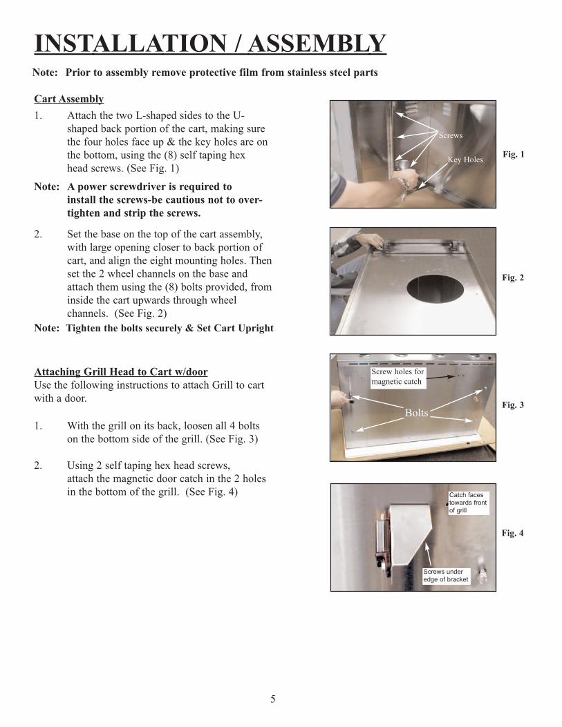
Cart Assembly1. Attach the two L-shaped sides to the U-
shaped back portion of the cart, making sure the four holes face up & the key holes are on the bottom, using the (8) self taping hexhead screws. (See Fig. 1)
Note: A power screwdriver is required to install the screws-be cautious not to over-tighten and strip the screws.
2. Set the base on the top of the cart assembly, with large opening closer to back portion of cart, and align the eight mounting holes. Then set the 2 wheel channels on the base and attach them using the (8) bolts provided, from inside the cart upwards through wheel channels. (See Fig. 2)
Note: Tighten the bolts securely & Set Cart Upright
Attaching Grill Head to Cart w/doorUse the following instructions to attach Grill to cartwith a door.
1. With the grill on its back, loosen all 4 bolts on the bottom side of the grill. (See Fig. 3)
2. Using 2 self taping hex head screws, attach the magnetic door catch in the 2 holes in the bottom of the grill. (See Fig. 4)
Fig. 2
Fig. 3
Note: Prior to assembly remove protective film from stainless steel parts
Fig. 1
Bolts
Screws
Key Holes
Screws underedge of bracket
Catch facestowards frontof grill
Fig. 4
Screw holes formagnetic catch
INSTALLATION / ASSEMBLY
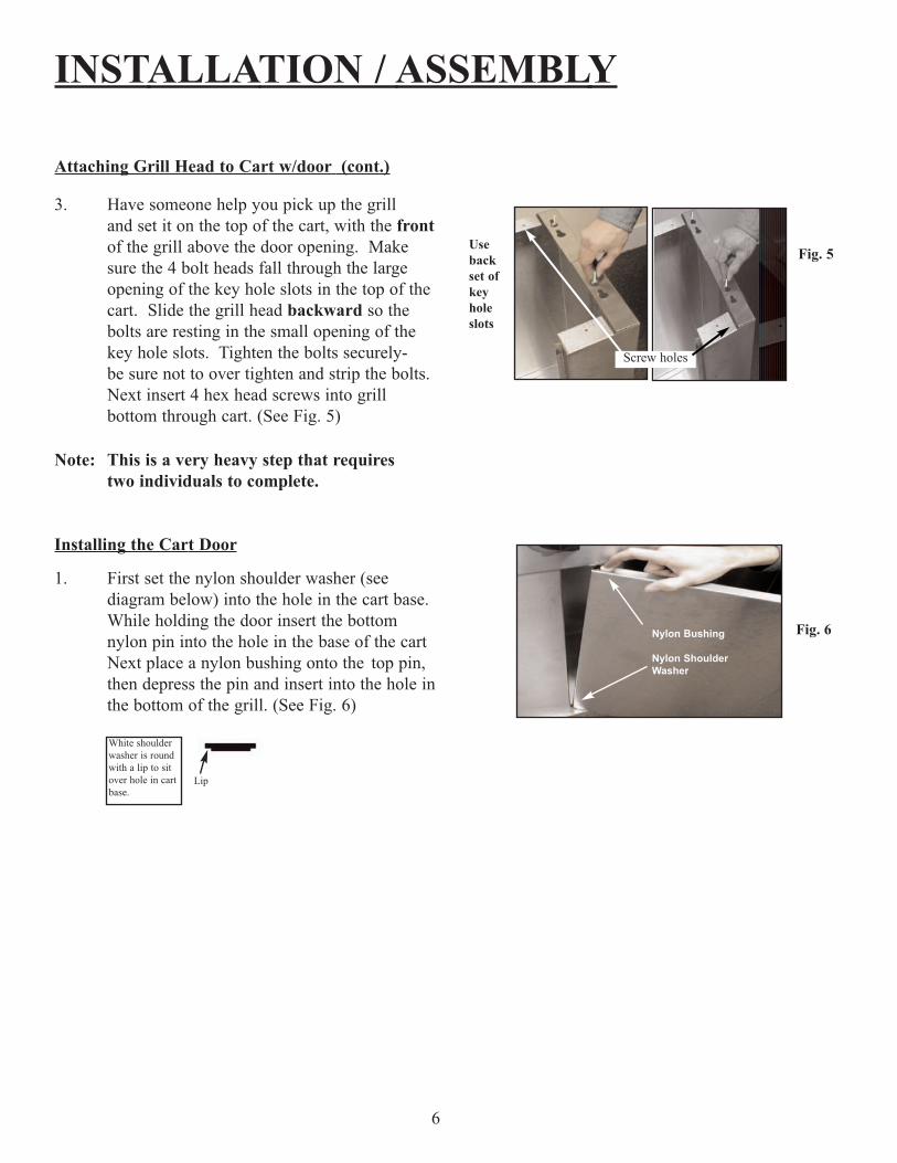
Attaching Grill Head to Cart w/door (cont.)
3. Have someone help you pick up the grill and set it on the top of the cart, with the front of the grill above the door opening. Make sure the 4 bolt heads fall through the large opening of the key hole slots in the top of the cart. Slide the grill head backward so the bolts are resting in the small opening of the key hole slots. Tighten the bolts securely-be sure not to over tighten and strip the bolts. Next insert 4 hex head screws into grill bottom through cart. (See Fig. 5)
Note: This is a very heavy step that requires two individuals to complete.
Installing the Cart Door
1. First set the nylon shoulder washer (see diagram below) into the hole in the cart base. While holding the door insert the bottom nylon pin into the hole in the base of the cart Next place a nylon bushing onto the top pin, then depress the pin and insert into the hole inthe bottom of the grill. (See Fig. 6)
6
Screw holes
Fig. 5Usebackset ofkeyholeslots
Fig. 6Nylon Bushing
Nylon ShoulderWasher
Lip
White shoulderwasher is roundwith a lip to sitover hole in cartbase.

INSTALLATION / ASSEMBLY
Side Shelves Attachment
1. Attach the shelves to each side of grill by inserting the shelf hooks into the slots on the side of the grill and pushing down on the shelfassembly until level with grill. (See Fig. 7)
2. Lock the shelves in place by inserting (2) self taping screws into each shelf. (See Fig. 8)
Interior parts installation
1. Check to make sure the bottom (3) Flavor Grids are correctly installed in the cutouts andaround the ignitors, as they may have shifted during shipment. (See Fig. 9)
2. Insert the second row of (3) Flavor Grids into cutouts with triangle ridges facing up. (See Fig. 9A)
3. Install cooking grates on the ledges provided on the grill to create your cooking surface. (placing the one with a thumb hole in the middle) (See. Fig. 10)
4. Place warming shelf on support brackets by setting it flat across brackets allowing the two holes to line up with the stops on each bracket. (See Fig. 11)
7
Fig. 7
Fig. 8
Fig. 9
Fig. 10Fig. 11
Fig. 9A
GAS REQUIREMENTS
8
General InformationVerify the type of gas supply to be used, either Natural Gas (NG) or Liquid Propane (L.P)., and make sure themarking plate (located on the back of the unit) agrees with that of the supply.
Note: Never attach an unregulated gas line to the appliance.
For Natural Gas installations, an installer must supply a gas shutoff valve that is easily accessible to the grill.All installer supplied parts must conform to local codes, or in the absence of local codes, with the NationalElectrical Code, ANSI/NFPA 70-1990, and the National Fuel Gas Code, ANSI Z223.1-1998.
All pipe sealants must be an approved type and resistant to the actions of L.P. gases. Never use pipe sealanton flare fittings. All gas connections should be made by a competent technician and in accordance with localcodes and ordinances. In the absence of local codes, the installation must comply with the National Fuel GasCode, ANSI Z223.1-1998. Gas conversions kits are available from the factory. When ordering gas conversionkits have the model number, and the type of gas (natural or L.P.) from your grill.
This Grill and its individual shut off valve must be disconnected from the gas supply piping system during anypressure testing of that system at test pressures in excess of 1/2 PSIG (3.5 kPa.).
This Grill must be isolated from the gas supply piping system by closing its individual manual shut-off valveduring any pressure testing of the gas supply piping system at test pressures equal to or less than 1/2 PSIG(3.5 kPa.).
The installation of this Grill must conform with local codes, or in the absence of local codes , with NationalFuel Code, ANSI Z223.1a-1998.
Installation in Canada must be in accordance with the Standard Can1-b149.1 and or .2 (installation code forgas burning appliances and equipment) and local codes.
Natural Gas InstallationThe gas inlet supply pressure should be between 5” and 14” Water Column,(w.c.) A step down regulator isrequired if the line pressure is in excess of 14” w.c. Inlet pressure must not exceed 14” water column (1/2PSIG)
Check your local gas utility company or with local codes for instructions on installing gas supply lines. Besure to check on type and size of run, and how deep to bury the line. If the gas supply line is too small, thegrill will not operate correctly.
Any joint sealant used must be an approved type and be resistant to the actions of L.P. gases.
Attach the natural gas regulator (supplied with your grill) to the brass fitting coming out the bottom, backsideof the grill (be sure the arrow on the regulator is pointing up towards the grill). Attach your gas line to the3/8” flare fitting coming out of the natural gas regulator at the back of the grill.
Place the installer supplied shut-off valve in an accessible location to enable the gas supply to be cut off to theunit.

GAS REQUIREMENTS
L.P. Gas Installation
Jenn-Air Gas Grills that are set to operate with L.P. gas come with a high capacity hose and regulator assembly. This assembly is designed to connect directly to a standard 20 lb. L.P. cylinder.
Attach the gas hose assembly to the brass 3/8 flared fitting on the under side of the grill. Tighten securely andattach other end to the propane tank. (sold separately) (See Fig. 12)
L.P. Tank Information
Never use a dented or rusted L.P. tank or cylinder with a damaged valve.
The L.P. cylinder must be provided with a shut-off valve terminating in an L.P. gas supply cylinder outletspecified, as applicable, for connection No. 510 in the standard for compressed gas cylinder valve outlet andinlet connection ANSI/CGA-V-1. Cylinders must not be stored in a building, garage, or any other enclosedarea. (The L.P. cylinder must have an overfill protection device on it.)
The L.P. Gas supply cylinder must be constructed and marked in accordance with the specifications for L.P.gas cylinders of the U.S. Department of Transportation (DOT) or the National Standard of Canada,CAN/CAS-B339, “Cylinders, Spheres and Tubes for the Transportation of Dangerous Goods.”
9
Fig. 12
LEAK TESTING
General Information
Although all gas connections on the grill are leaked tested at the factory prior to shipment, a complete gastightness check must be performed at the installation site due to possible mishandling in shipment, or excessive pressure unknowingly being applied to the unit. Periodically check the whole system for leaks, orimmediately check if the smell of gas is detected.
Before Testing
Do Not smoke while leak testing. Extinguish all open flames. Never leak test with an open flame.
Mix a solution of equal parts mild detergent or liquid soap and water.
Testing
1. Turn off the burner control knobs.2. Turn the top knob of the fuel supply cylinder counterclockwise (right to left) one rotation to
open.3. Apply the soap solution to connections of the fuel supply assembly. If no soap bubbles
appear, the grill is ok to use. If bubbles form at the connections, a leak is detected.(If a leak is detected, immediately turn off the gas supply, tighten any leaking fittings, turn gas on, and recheck).
4. Turn off the knob on the fuel supply cylinder.5. Turn on the burner control knobs for a moment to release the pressure in the hose, then turn
the control knobs back off.6. Wash off soapy solution with cold water and towel dry.
Check all gas supply fittings before each use and each time the gas supply cylinder is connected to the regula-tor. Have a Qualified Service Technician leak test the grill any time a part of the gas system is replaced. Alsohave a Qualified Service Technician perform a leak test at least once a year whether or not the L.P. gas supplycylinder has been disconnected.
10
Note: If you cannot stop a gas leak turn off the gas supply and call your local gas utility, or the dealer you purchased the appliance from. If necessary, replace the
faulty part with a manufacture recommended replacement part.
USING THE GRILL
Grill Location
Do not use the grill in garages, breezeway, sheds or any enclosed area. Never operate the grill in enclosedareas as this could lead to a carbon monoxide buildup, which could result in injury or death. Place the grill ona level surface. Avoid moving the grill while it is operation.
Note: The grill will operate best if it is not facing directly into the wind.
Clearance to combustible construction - A minimum of 12” from the sides and back must be maintained fromthe gas grill above and below the cooking surface to adjacent vertical combustible construction.
Clearance to non-combustible construction - A minimum of 3” clearance from the back of the grill to non-combustible construction is required for the lid to fully open.
General Rules
Do Not leave the grill unattended while cooking!
1. Make sure the grill has been leak tested and is properly located.2. Light the grill burners using the instructions on in this manual.3. Turn the control knobs to “High” and preheat the grill for 10 minutes before cooking.4. Adjust heat settings to meet your cooking needs for desired results.5. Allow grill to cool down, wipe off any splatters or grease and clean the drip tray as needed.
11

LIGHTING THE GRILL
Before LightingWarning: Important! Before Lighting...
Check the gas supply line for cuts, wear or abrasion.
Always keep your face and body as far away from thegrill as possible when lighting.
Grill Burner Lighting
Lighting the Grill with electronic ignitorAlways open the lid before attempting lighting. Push and turn one of the control knobs counter clock-wise to the “HIGH” position and immediately pressthe electronic ignitor button. You’ll hear a snappingsound. It may be necessary to hold the electronicstarter button for about 4 seconds. If the burner doesnot light in 4 seconds, turn the knob to OFF and wait5 minutes before trying again. Repeat above steps tolight remaining burners. (See Fig. 13)
Match LightingIf by chance the electronic ignitor does not light theburner, the burner may be lit with a match. Keepyour face as far away from the Grill surface as possible and pass a lit, long stem match through thespaces in the Grill rack to the ports of the backcrossover burner between the flavor grids. Positionthe match near the burner ports and push and turn thecontrol knob counter clockwise to the “HIGH”position. (See Fig. 14)
12
Do not attempt to
“Light” the grill if the
odor of gas is present!!
Fig. 13
Fig. 14
Note: If the grill will not light after several attempts see the Trouble-shooting section of this manual.Turn the control knobs to the OFF position when not in use.
USING THE ROTISSERIE BURNER(Optional ROTISSERIE KIT for use with Back Infrared Burner must be purchased separately)
The grill rotisserie system is designed to cook items from the back using infrared heat. The rotisserie burneris an infrared type which provides intense searing radiant heat. Preferred by chefs over other cooking methods,this intense heat is magnificent for searing in the natural juices and nutrients found in quality cuts of meats.
Once lit, the rotisserie burner will reach cooking temperatures in 1 minute. The orange/red glow will even outin about 5 minutes. The rotisserie motor is equipped with metal gears and is capable of turning up to 20 lbs.of food. The motor is mounted on a bracket on the left side of the grill by sliding the motor over the bracketwith the cord facing the back of the grill. Make sure the motor is straight prior to operating.
13
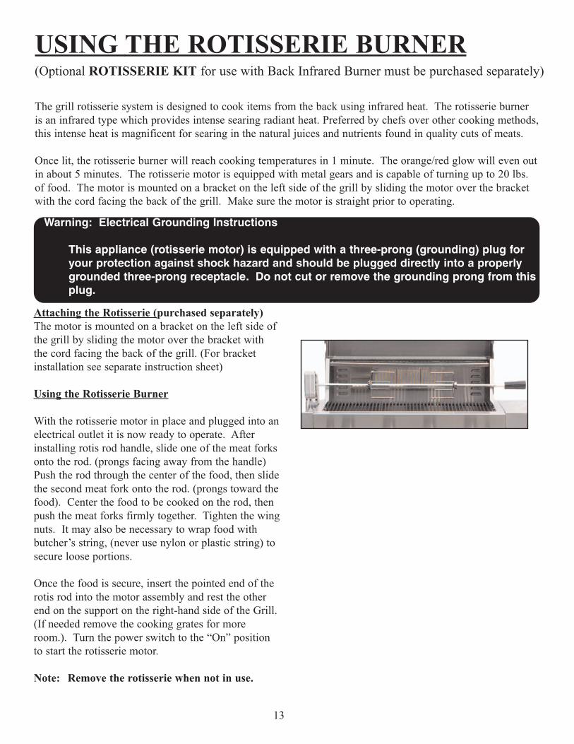
Attaching the Rotisserie (purchased separately)The motor is mounted on a bracket on the left side ofthe grill by sliding the motor over the bracket withthe cord facing the back of the grill. (For bracketinstallation see separate instruction sheet)
Using the Rotisserie Burner
With the rotisserie motor in place and plugged into anelectrical outlet it is now ready to operate. Afterinstalling rotis rod handle, slide one of the meat forksonto the rod. (prongs facing away from the handle)Push the rod through the center of the food, then slidethe second meat fork onto the rod. (prongs toward thefood). Center the food to be cooked on the rod, thenpush the meat forks firmly together. Tighten the wingnuts. It may also be necessary to wrap food withbutcher’s string, (never use nylon or plastic string) tosecure loose portions.
Once the food is secure, insert the pointed end of therotis rod into the motor assembly and rest the otherend on the support on the right-hand side of the Grill.(If needed remove the cooking grates for moreroom.). Turn the power switch to the “On” positionto start the rotisserie motor.
Note: Remove the rotisserie when not in use.
Warning: Electrical Grounding Instructions
This appliance (rotisserie motor) is equipped with a three-prong (grounding) plug for your protection against shock hazard and should be plugged directly into a properly grounded three-prong receptacle. Do not cut or remove the grounding prong from thisplug.
USING THE ROTISSERIE BURNER
Rotisserie Lighting
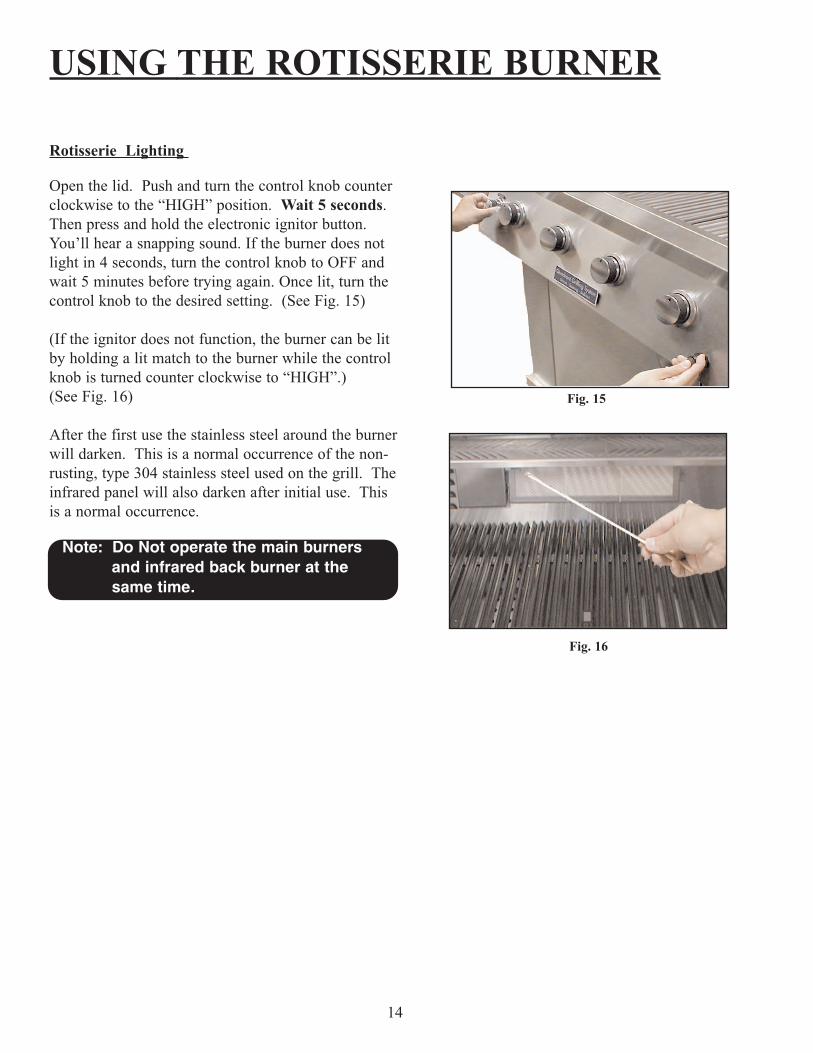
Open the lid. Push and turn the control knob counterclockwise to the “HIGH” position. Wait 5 seconds.Then press and hold the electronic ignitor button.You’ll hear a snapping sound. If the burner does notlight in 4 seconds, turn the control knob to OFF andwait 5 minutes before trying again. Once lit, turn thecontrol knob to the desired setting. (See Fig. 15)
(If the ignitor does not function, the burner can be litby holding a lit match to the burner while the controlknob is turned counter clockwise to “HIGH”.) (See Fig. 16)
After the first use the stainless steel around the burnerwill darken. This is a normal occurrence of the non-rusting, type 304 stainless steel used on the grill. Theinfrared panel will also darken after initial use. Thisis a normal occurrence.
14
Fig. 15
Fig. 16
Note: Do Not operate the main burners and infrared back burner at the same time.
CARE and MAINTENANCE
Drip Tray
The drip tray located below the grill, inside the cart, should be cleaned periodically to prevent heavy buildupof debris.
Note: Allow the drip tray to cool before attempting to clean.
Cooking Grates
The cooking grates can be cleaned immediately after cooking is completed and after turning off the flame.Wear a barbecue mitt and scrub the cooking grates with a damp cloth. If the grill is allowed to cool down,cleaning the grates will be easier if removed from the grill and cleaned with a mild detergent.
Stainless Steel
The grill is made from a non-rusting stainless steel. After initial usage, areas of the grill may discolor fromthe intense heat given off by the burners, this is normal.
Purchase a mild stainless steel cleaner and rub in the direction of the grain of the metal. Specks of grease cangather on the surface of the stainless steel and bake on to the surface and give a worn appearance. Forremoval use an non-abrasive oven cleaner in conjunction with a stainless cleaner.
Note: Always scrub in the direction of the grain.
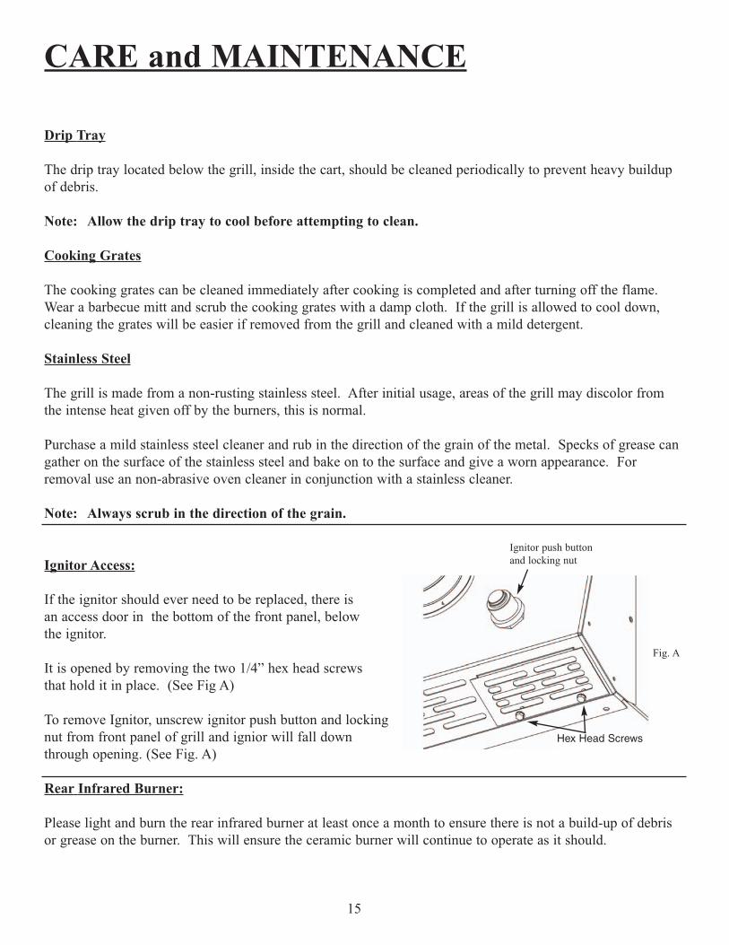
Ignitor Access:
If the ignitor should ever need to be replaced, there isan access door in the bottom of the front panel, below the ignitor.
It is opened by removing the two 1/4” hex head screws that hold it in place. (See Fig A)
To remove Ignitor, unscrew ignitor push button and lockingnut from front panel of grill and ignior will fall down through opening. (See Fig. A)
Rear Infrared Burner:
Please light and burn the rear infrared burner at least once a month to ensure there is not a build-up of debrisor grease on the burner. This will ensure the ceramic burner will continue to operate as it should.
15
Hex Head Screws
Fig. A
Ignitor push buttonand locking nut

TROUBLE SHOOTING
General Trouble Shooting
You should inspect the burners at least once a year or immediately if any of the following conditions occur:The smell of gas in conjunction with the burner flames appearing yellow.The Grill does not reach temperature.The burners make a popping noise.The Grill heats unevenly.
Before calling customer service
If the Grill does not function properly, use the following checklist.
16
Problem
Grill will not light when the ignitor button is pushed.
Low heat with knob in “High” position.
SolutionAfter opening tank valve, be sure one of the Grill control knobs is on high for at least 4 seconds while pushing ignitor button.
Check tank fuel level.
Check for loose wire connections.
Remove the cooking grates and flavor grids. Push ignitor button, and check for spark on tip of electrode.
Check to see if debris is blocking the electrode sparks.
Check battery/replace battery.
Attempt to match light the burner.
If using L.P. gas, disconnect gas line at tank, then reconnect.
Check for proper gas supply and pressure.
If using L.P. gas check for low fuel level.
If using L.P. gas check for kinks in supply line.
If only one burner appears low, clear burner ports of any obstructions.
Pre-heat Grill for a full 10 minutes.
If using L.P. gas, disconnect gas line at tank,then reconnect.

TROUBLE SHOOTING
17
Problem
Flame is erratic
Flare-Ups
Burner flame is yellow or orange, in conjunction with theodor of gas.
Cart door does not align properly with cart
Solution
Check gas connection.
Fuel level may be low.
Grill may be in need of cleaning.
Check flavor grids and cooking grates for excess build-up.
Ensure Grill is not placed directly in path of wind.
Be sure the drip tray is clean. (do not use aluminum foil in drip tray)
Check the burner inlet for obstructions.
Grill may be in a windy area. Move to a less windy area if possible.
Loosen the four bolts that attach grill head to cart. Slide grill head either to the left or right until door is aligned properly. Retighten the bolts.
Spider and Insect Warning
Spider and insects can nest in the burners of this or any other Grill and cause the gas to flow from the front of the burner. This is very dangerous condition which can cause a fire to occur behind the valve panel, thereby damaging theGrill and making it unsafe to operate. We recommend you check at least once a year to be safe.

WARRANTY
LIMITED LIFETIME WARRANTY
If you have other questions about your Jenn-Air grill, please contact: Sure Heat Customer Service Hotline
(800) 229-5647
Because of continuing product improvement these specifications are subject to change without notice.
11/2002
18
Jenn-Air Grills from Sure Heat, have a Lifetime Warranty on all stainless steel parts, 15 years on stainless burners and a 5 year warranty on all other parts.
IMPORTANT: We recommend you return the warranty registration card so that you can be contacted with any questions of safety arise that could affect you. The return of the warranty registration card is not a condition for warranty coverage.
LIMITED WARRANTY
If the Jenn-Air Grill does not operate properly, first thoroughly carry out the instructions provided withthe unit to ensure that the appliance is installed correctly and check the Troubleshooting section.
•The warranty is nontransferable.
•The warranty is for replacement of defective parts only. Sure Heat will not be responsible for damageresulting from accident, alteration, misuse, abuse, hostile environments, improper installation or installation not in accordance with local codes.
•This limited warranty does not cover corrosion or discoloring due to lack of maintenance, misuse, hostile environments, alterations, accidents or abuse or neglect.
•This limited warranty does not cover any scratches, dents, corrosion or discoloring by heat, abrasiveand chemical cleaners nor any components used in the installation of the appliance.
Jenn-Air is a registered trademark of the Maytag Corporation and is used under license to Lowe’s Companies Inc.