Embed Size (px)
Citation preview
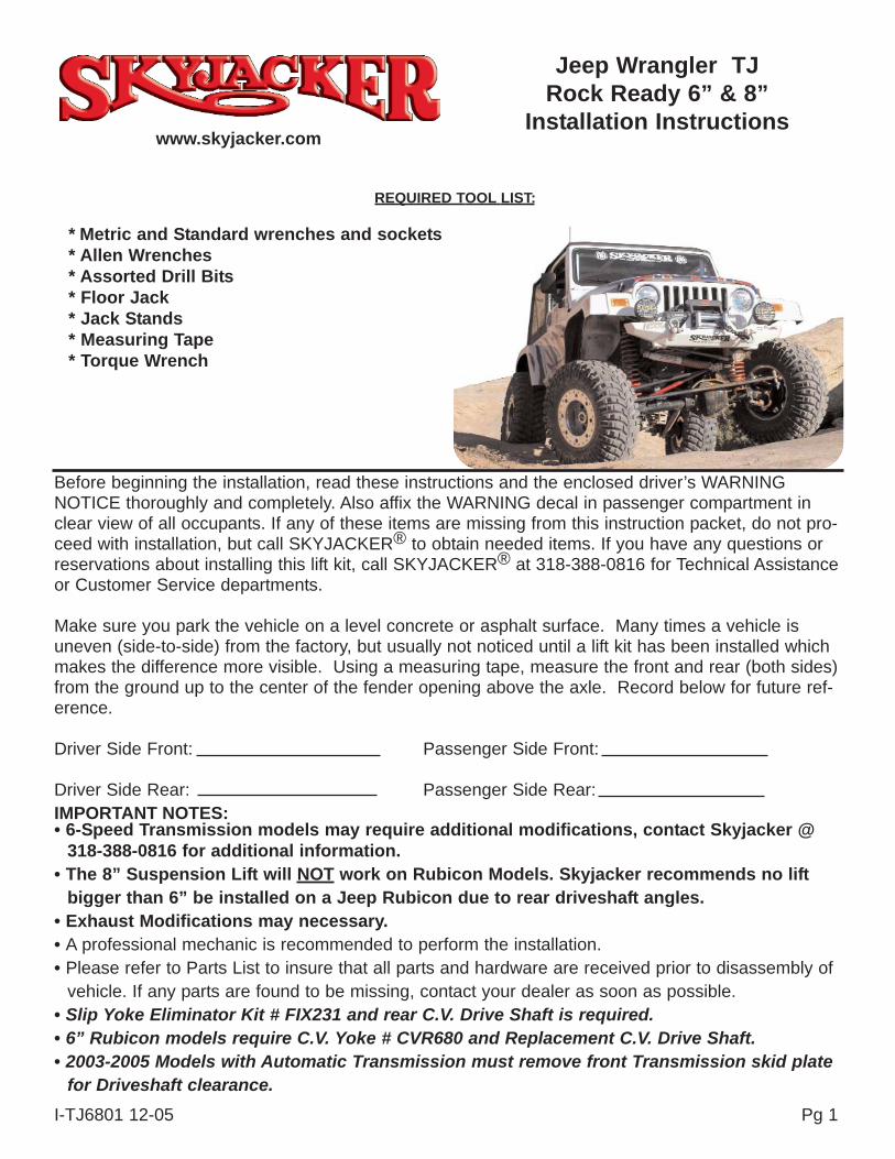
Before beginning the installation, read these instructions and the enclosed driver’s WARNINGNOTICE thoroughly and completely. Also affix the WARNING decal in passenger compartment inclear view of all occupants. If any of these items are missing from this instruction packet, do not pro-ceed with installation, but call SKYJACKER® to obtain needed items. If you have any questions orreservations about installing this lift kit, call SKYJACKER® at 318-388-0816 for Technical Assistanceor Customer Service departments.
Make sure you park the vehicle on a level concrete or asphalt surface. Many times a vehicle isuneven (side-to-side) from the factory, but usually not noticed until a lift kit has been installed whichmakes the difference more visible. Using a measuring tape, measure the front and rear (both sides)from the ground up to the center of the fender opening above the axle. Record below for future ref-erence.
Driver Side Front: Passenger Side Front:
Driver Side Rear: Passenger Side Rear:IMPORTANT NOTES:• 6-Speed Transmission models may require additional modifications, contact Skyjacker @
318-388-0816 for additional information.• The 8” Suspension Lift will NOT work on Rubicon Models. Skyjacker recommends no lift
bigger than 6” be installed on a Jeep Rubicon due to rear driveshaft angles.• Exhaust Modifications may necessary.• A professional mechanic is recommended to perform the installation.• Please refer to Parts List to insure that all parts and hardware are received prior to disassembly of
vehicle. If any parts are found to be missing, contact your dealer as soon as possible.• Slip Yoke Eliminator Kit # FIX231 and rear C.V. Drive Shaft is required.• 6” Rubicon models require C.V. Yoke # CVR680 and Replacement C.V. Drive Shaft.• 2003-2005 Models with Automatic Transmission must remove front Transmission skid plate
for Driveshaft clearance.
Jeep Wrangler TJRock Ready 6” & 8”
Installation Instructions
REQUIRED TOOL LIST:
* Metric and Standard wrenches and sockets* Allen Wrenches* Assorted Drill Bits* Floor Jack* Jack Stands* Measuring Tape* Torque Wrench
www.skyjacker.com
I-TJ6801 12-05 Pg 1
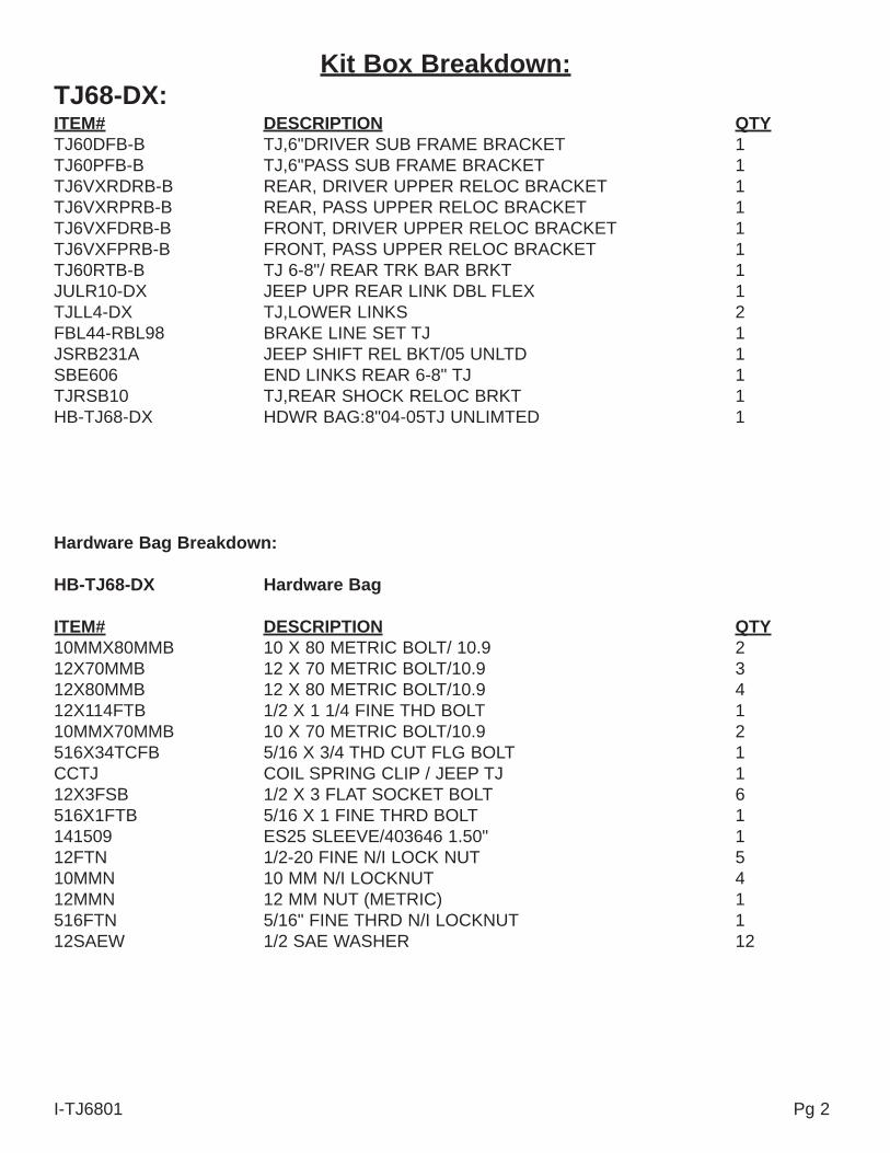
Kit Box Breakdown:TJ68-DX:ITEM# DESCRIPTION QTYTJ60DFB-B TJ,6"DRIVER SUB FRAME BRACKET 1TJ60PFB-B TJ,6"PASS SUB FRAME BRACKET 1TJ6VXRDRB-B REAR, DRIVER UPPER RELOC BRACKET 1TJ6VXRPRB-B REAR, PASS UPPER RELOC BRACKET 1TJ6VXFDRB-B FRONT, DRIVER UPPER RELOC BRACKET 1TJ6VXFPRB-B FRONT, PASS UPPER RELOC BRACKET 1TJ60RTB-B TJ 6-8"/ REAR TRK BAR BRKT 1JULR10-DX JEEP UPR REAR LINK DBL FLEX 1TJLL4-DX TJ,LOWER LINKS 2FBL44-RBL98 BRAKE LINE SET TJ 1JSRB231A JEEP SHIFT REL BKT/05 UNLTD 1SBE606 END LINKS REAR 6-8" TJ 1TJRSB10 TJ,REAR SHOCK RELOC BRKT 1HB-TJ68-DX HDWR BAG:8"04-05TJ UNLIMTED 1
Hardware Bag Breakdown:
HB-TJ68-DX Hardware Bag
ITEM# DESCRIPTION QTY10MMX80MMB 10 X 80 METRIC BOLT/ 10.9 212X70MMB 12 X 70 METRIC BOLT/10.9 312X80MMB 12 X 80 METRIC BOLT/10.9 412X114FTB 1/2 X 1 1/4 FINE THD BOLT 110MMX70MMB 10 X 70 METRIC BOLT/10.9 2516X34TCFB 5/16 X 3/4 THD CUT FLG BOLT 1CCTJ COIL SPRING CLIP / JEEP TJ 112X3FSB 1/2 X 3 FLAT SOCKET BOLT 6516X1FTB 5/16 X 1 FINE THRD BOLT 1141509 ES25 SLEEVE/403646 1.50" 112FTN 1/2-20 FINE N/I LOCK NUT 510MMN 10 MM N/I LOCKNUT 412MMN 12 MM NUT (METRIC) 1516FTN 5/16" FINE THRD N/I LOCKNUT 112SAEW 1/2 SAE WASHER 12
Pg 2I-TJ6801
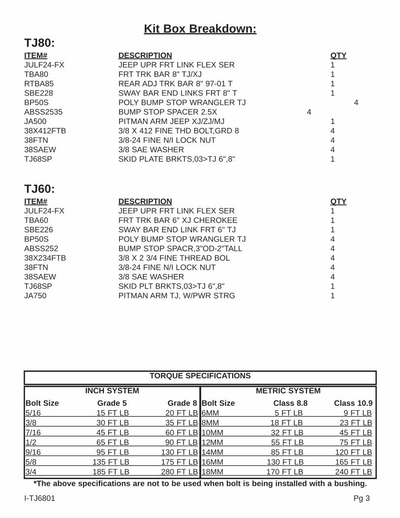
Kit Box Breakdown:TJ80:ITEM# DESCRIPTION QTYJULF24-FX JEEP UPR FRT LINK FLEX SER 1TBA80 FRT TRK BAR 8" TJ/XJ 1RTBA85 REAR ADJ TRK BAR 8" 97-01 T 1SBE228 SWAY BAR END LINKS FRT 8" T 1BP50S POLY BUMP STOP WRANGLER TJ 4ABSS2535 BUMP STOP SPACER 2.5X 4JA500 PITMAN ARM JEEP XJ/ZJ/MJ 138X412FTB 3/8 X 412 FINE THD BOLT,GRD 8 438FTN 3/8-24 FINE N/I LOCK NUT 438SAEW 3/8 SAE WASHER 4TJ68SP SKID PLATE BRKTS,03>TJ 6",8" 1
TJ60:ITEM# DESCRIPTION QTYJULF24-FX JEEP UPR FRT LINK FLEX SER 1TBA60 FRT TRK BAR 6" XJ CHEROKEE 1SBE226 SWAY BAR END LINK FRT 6" TJ 1BP50S POLY BUMP STOP WRANGLER TJ 4ABSS252 BUMP STOP SPACR,3"OD-2"TALL 438X234FTB 3/8 X 2 3/4 FINE THREAD BOL 438FTN 3/8-24 FINE N/I LOCK NUT 438SAEW 3/8 SAE WASHER 4TJ68SP SKID PLT BRKTS,03>TJ 6",8" 1JA750 PITMAN ARM TJ, W/PWR STRG 1
I-TJ6801 Pg 3
TORQUE SPECIFICATIONS
INCH SYSTEMBolt Size Grade 5 Grade 85/16 15 FT LB 20 FT LB3/8 30 FT LB 35 FT LB7/16 45 FT LB 60 FT LB1/2 65 FT LB 90 FT LB9/16 95 FT LB 130 FT LB5/8 135 FT LB 175 FT LB3/4 185 FT LB 280 FT LB
METRIC SYSTEMBolt Size Class 8.8 Class 10.9 6MM 5 FT LB 9 FT LB8MM 18 FT LB 23 FT LB10MM 32 FT LB 45 FT LB12MM 55 FT LB 75 FT LB14MM 85 FT LB 120 FT LB16MM 130 FT LB 165 FT LB18MM 170 FT LB 240 FT LB
*The above specifications are not to be used when bolt is being installed with a bushing.
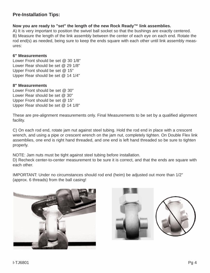
Pre-Installation Tips:
Now you are ready to "set" the length of the new Rock Ready™ link assemblies.A) It is very important to position the swivel ball socket so that the bushings are exactly centered.B) Measure the length of the link assembly between the center of each eye on each end. Rotate therod end(s) as needed, being sure to keep the ends square with each other until link assembly meas-ures:
6" MeasurementsLower Front should be set @ 30 1/8"Lower Rear should be set @ 29 1/8"Upper Front should be set @ 15"Upper Rear should be set @ 14 1/4"
8" MeasurementsLower Front should be set @ 30"Lower Rear should be set @ 30"Upper Front should be set @ 15"Upper Rear should be set @ 14 1/8"
These are pre-alignment measurements only. Final Measurements to be set by a qualified alignmentfacility.
C) On each rod end, rotate jam nut against steel tubing. Hold the rod end in place with a crescentwrench, and using a pipe or crescent wrench on the jam nut, completely tighten. On Double Flex linkassemblies, one end is right hand threaded, and one end is left hand threaded so be sure to tightenproperly.
NOTE: Jam nuts must be tight against steel tubing before installation.D) Recheck center-to-center measurement to be sure it is correct, and that the ends are square witheach other.
IMPORTANT: Under no circumstances should rod end (heim) be adjusted out more than 1/2"(approx. 6 threads) from the ball casing!
I-TJ6801 Pg 4
Front:
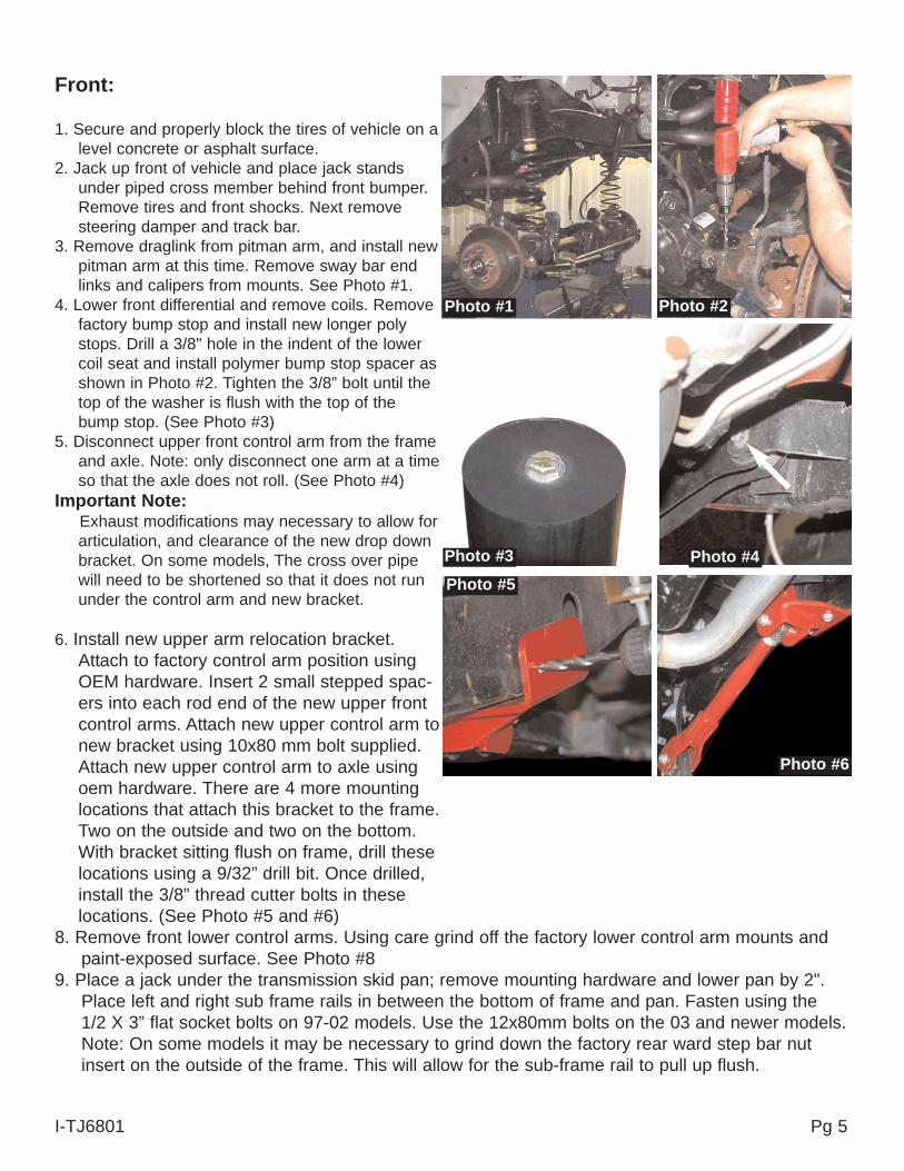
1. Secure and properly block the tires of vehicle on alevel concrete or asphalt surface.
2. Jack up front of vehicle and place jack standsunder piped cross member behind front bumper.Remove tires and front shocks. Next removesteering damper and track bar.
3. Remove draglink from pitman arm, and install newpitman arm at this time. Remove sway bar endlinks and calipers from mounts. See Photo #1.
4. Lower front differential and remove coils. Removefactory bump stop and install new longer polystops. Drill a 3/8" hole in the indent of the lowercoil seat and install polymer bump stop spacer asshown in Photo #2. Tighten the 3/8” bolt until thetop of the washer is flush with the top of thebump stop. (See Photo #3)
5. Disconnect upper front control arm from the frameand axle. Note: only disconnect one arm at a timeso that the axle does not roll. (See Photo #4)
Important Note:Exhaust modifications may necessary to allow forarticulation, and clearance of the new drop downbracket. On some models, The cross over pipewill need to be shortened so that it does not rununder the control arm and new bracket.
6. Install new upper arm relocation bracket.Attach to factory control arm position usingOEM hardware. Insert 2 small stepped spac-ers into each rod end of the new upper frontcontrol arms. Attach new upper control arm tonew bracket using 10x80 mm bolt supplied.Attach new upper control arm to axle usingoem hardware. There are 4 more mountinglocations that attach this bracket to the frame.Two on the outside and two on the bottom.With bracket sitting flush on frame, drill theselocations using a 9/32” drill bit. Once drilled,install the 3/8” thread cutter bolts in theselocations. (See Photo #5 and #6)
8. Remove front lower control arms. Using care grind off the factory lower control arm mounts andpaint-exposed surface. See Photo #8
9. Place a jack under the transmission skid pan; remove mounting hardware and lower pan by 2".Place left and right sub frame rails in between the bottom of frame and pan. Fasten using the1/2 X 3” flat socket bolts on 97-02 models. Use the 12x80mm bolts on the 03 and newer models.Note: On some models it may be necessary to grind down the factory rear ward step bar nutinsert on the outside of the frame. This will allow for the sub-frame rail to pull up flush.
I-TJ6801 Pg 5
Photo #1 Photo #2
Photo #4Photo #5
Photo #6
Photo #3
10. Install the new transfer case shifter bracket (part # JSRB231A) using theinstructions provided.
11. With new Sub-Frame attached by the bottom bolts, drill the outer mount-ing locations using a 1/2” drill bit. Drill completely through frame andmounting tab located on back side of sub frame rail. (See Photo #9)Once Drilled , install the 1/2 x 4” fine thread bolt, washers and nuts.Torque to 70 Ft. Lbs.
12. The new lower control arms (22.75" tube length) mount to the OEMlower location at the differential and to the new position of the sub frame.Insert 2 large stepped spacers into each rod end of the new lower con-trol arms and fasten using the original hardware. (See Photo #10)
13. Lower front differential and install the new coils plac-ing the top of the coil over the upper bump stopmount first. Provided with the springs is the clip andhardware (See Photo #11) to fasten the passengerfront coil like the driver’s side. The manufacturerprovides the hole in the left lower coil mount for youto fasten the coil securely to its seat. Install same asdriver side.
14. Install new adjustable track bar by first greasing andinstalling poly bushing #2888 and sleeve #51792.Insert poly end into the OEM steering damper loca-tion on passenger side of axle, NOT the original track barlocation. Install new steering damper mounting bracket: tabgoes over the sway bar end link stud with original nut, usethe new 1/2" x 2 1/2" flat socket head bolt and stover nut tobolt new bracket to track bar. See Photo #12. In extreme sit-uations depending on pinion angle and caster settings, thedrag link may contact this bracket when turning. This bracket can beslightly ground for additional clearance.Next install frame end of track bar by following the hardware as shown inPhotos #13 & 14, being sure to keep rod end square (parallel) with framemount. NOTE: Be sure not more than 1/2" of threads are extended frombar (including jam nut). Hold the rod end in place with a crescent wrench,using a wrench on the jam nut, completely tighten.
I-TJ6801 Pg 6
Photo #8
Photo #9Photo #10
Photo #11
Photo #12
Photo #14
Photo #13
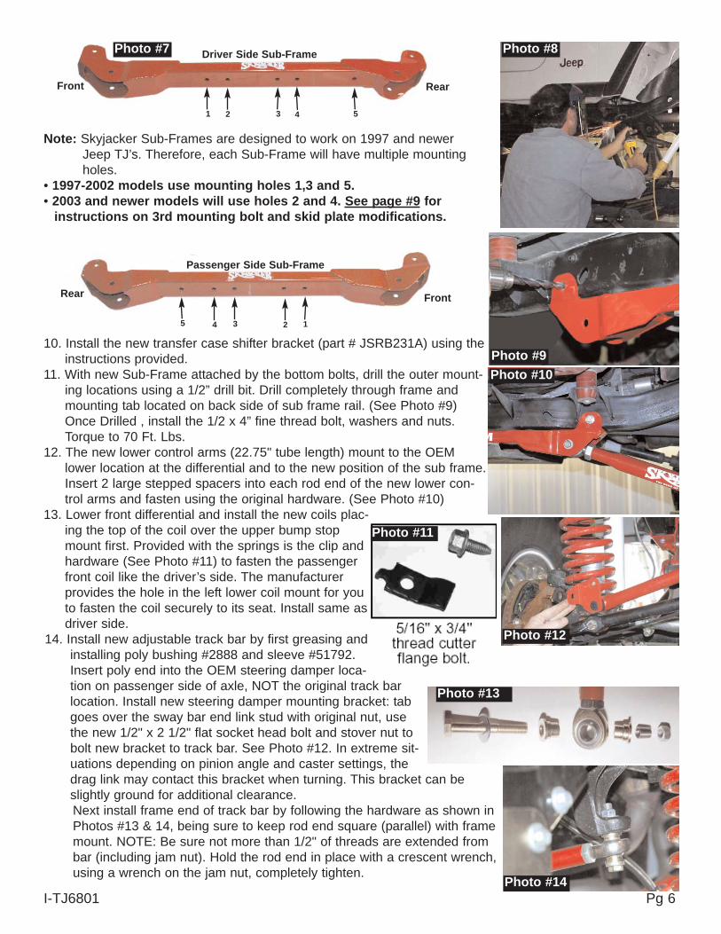
Driver Side Sub-Frame
Passenger Side Sub-Frame
Front
Front
Rear
Rear
1
12
2 3
3
4
4
5
5
Photo #7
Note: Skyjacker Sub-Frames are designed to work on 1997 and newerJeep TJ’s. Therefore, each Sub-Frame will have multiple mountingholes.
• 1997-2002 models use mounting holes 1,3 and 5.• 2003 and newer models will use holes 2 and 4. See page #9 for
instructions on 3rd mounting bolt and skid plate modifications.
I-TJ6801 Pg 7
15. Install steering damper mounting stud in hole of drag link and uppermounting hole on new track bar bracket. Install the provided 5/8 hour-glass bushings into new steering stabilizer and attach onto new studs.(See Photo #15) Install front brake lines using instructions packaged withbrake line kit.
Rear:
17. Raise and support vehicle under rear cross member with two jack stands.Remove rear tires and shock absorbers.
18. Disconnect rear track bar from differential and sway bar end links, lowerdifferential and remove rear coils.
19. Drill a 3/8" hole into center of rear lower spring seat and install polymerbump stop spacer. See Photo #16. Tighten the 3/8” bolt until the top of thewasher is flush with the top of the bump stop. (See Photo #16A) Removeupper bump stop by pulling back and forth with pliers. Replace with newpoly bump stop. Install new rear coils.
20. Place new track bar relocating bracket over the oem track bar mount at differential. Place the new 12mmx 70mm bolt through the original track bar location. Use the supplied spacer (#54314) to fill the spacewhere the oem track bar was located. Apply lock nut and tighten. Drill a 1/2" hole through the hole in thedriver’s side of the new bracket. Install the 1/2" x 1 1/4" bolt with washers on each side through the newlydrilled hole and tighten with self locking nut. Install the 5/16" x 1" fine thread bolt, washers and nut intothe forward hole of the new bracket. (See Photo #17). Place the track bar into the upper hole of the newbracket using the original hardware and tighten once vehicle has been lowered to the ground. Be sure toinstall both upper and lower bolts from the rear, forward as shown in Photo #17. 8” lifts come with anadjustable rear track bar and special instructions.
Photo #15
Photo #16
Photo #16A
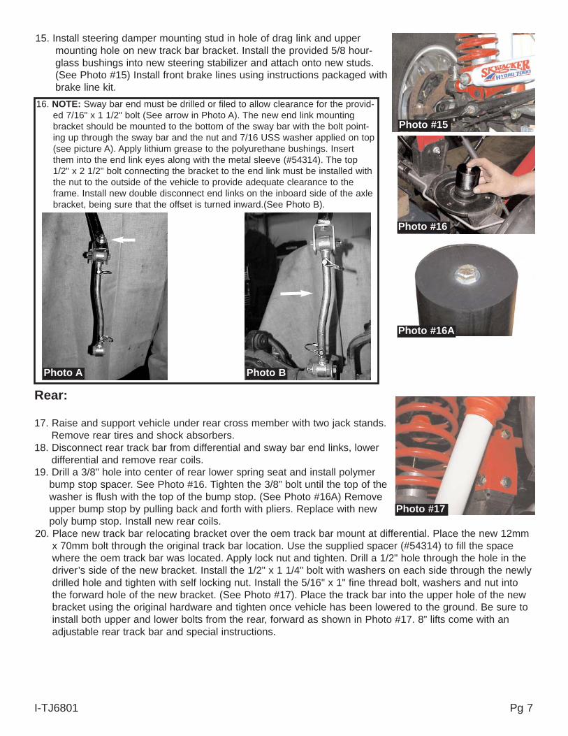
16. NOTE: Sway bar end must be drilled or filed to allow clearance for the provid-ed 7/16" x 1 1/2" bolt (See arrow in Photo A). The new end link mountingbracket should be mounted to the bottom of the sway bar with the bolt point-ing up through the sway bar and the nut and 7/16 USS washer applied on top(see picture A). Apply lithium grease to the polyurethane bushings. Insertthem into the end link eyes along with the metal sleeve (#54314). The top1/2" x 2 1/2" bolt connecting the bracket to the end link must be installed withthe nut to the outside of the vehicle to provide adequate clearance to theframe. Install new double disconnect end links on the inboard side of the axlebracket, being sure that the offset is turned inward.(See Photo B).
Photo A Photo B
Photo #17
21. Remove upper control arms (freeing rear brake line and emergency cables)and rear sway bar end links. Install new upper arm relocating brackets. Thesebrackets and control arms will install the same as the front. Only install one ata time so that the axle does not roll.
Note: The rear upper link brackets feature 2 mounting locations for the upperarms. Arrow in Photo# 18 shows the correct mounting for an 8” lift. If installingthe Skyjacker 6” lift, you must use the forward most hole in the bracket.
22. Install new upper control arms (10" tube length) into newupper frame mount using 10mm hardware provided.
23. If vehicle is equipped with an optional upper control armeccentric cam bolt they must be reused. Attach factoryemergency brake bracket to the new upper control armbracket using the zip-tie provided.
24. Assemble the new rear sway bar end links by applyinggrease to the poly bushings and insert them into eacheye along with a sleeve #54587. Install using originalhardware.
25. Remove lower control arms and rear lower control armmounts at frame. Repeat process from front lower controlarm mount. Clean and paint exposed surfaces. The new rear lower control arms (22.75" tube length)mount to the OEM lower location at the differential and to the new position of the sub frame. Insert 2large stepped spacers into each rod end of the new lower control arms and fasten using the original hard-ware. See Photo #19.
26. Install rear brake line. Install rear coils and shocks. Reinstall tires and lower vehicle to ground.
Final Notes:
• Alignment is necessary, so after the lift is installed have a qualified alignment center realign the vehicle tofactory specifications.
• Rotate driveshafts and check for interference at differential yoke and cardan joint. If necessary, lightly dresscasting(s) and/or U-joint tabs in order to eliminate binding.
• Ensure there is adequate clearance between exhaust and brakelines, fuel lines, fuel tank, floor board, andwiring harnesses. Check steering gear for interference and proper working order. Inspect brakelines fordamage and adequate clearance. Test brake system before driving.
• With the vehicle on the floor, cycle steering lock to lock and inspect steering, suspension, driveline andbrakeline systems for proper operation, tightness and adequate clearance.
• Have headlights readjusted to proper settings
Available Accessories:
• Heavy Duty Steering Box Skid Plate Part # SSP10• Heavy Duty Tie Rod Tube Part # TR300
I-TJ6801 Pg 8
Photo #18
Photo #19
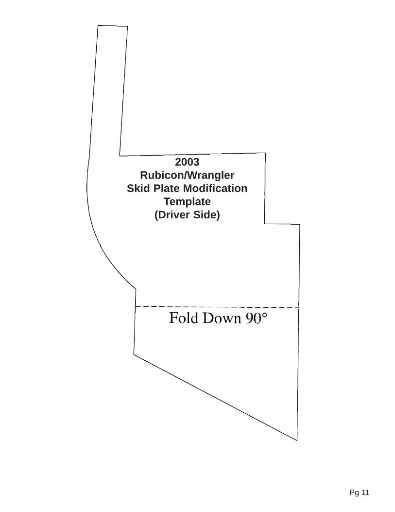
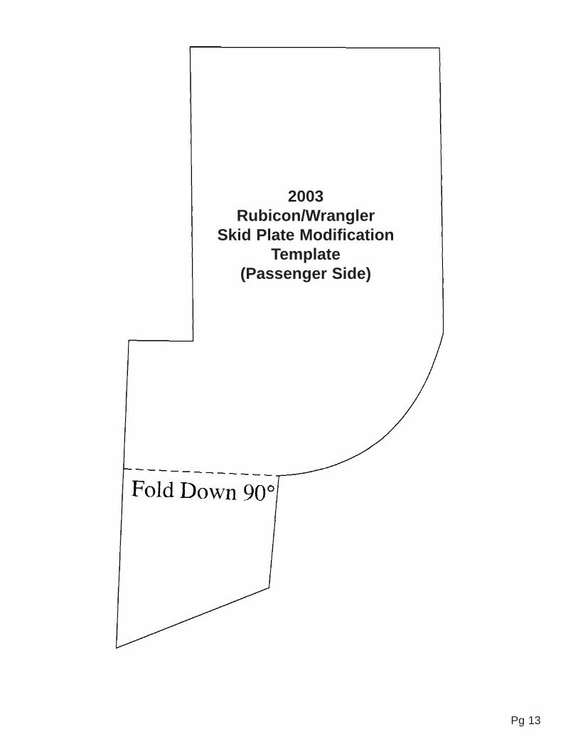
2003 - Newer TJ 6-10” Rock ReadySkid Plate Modification Supplement
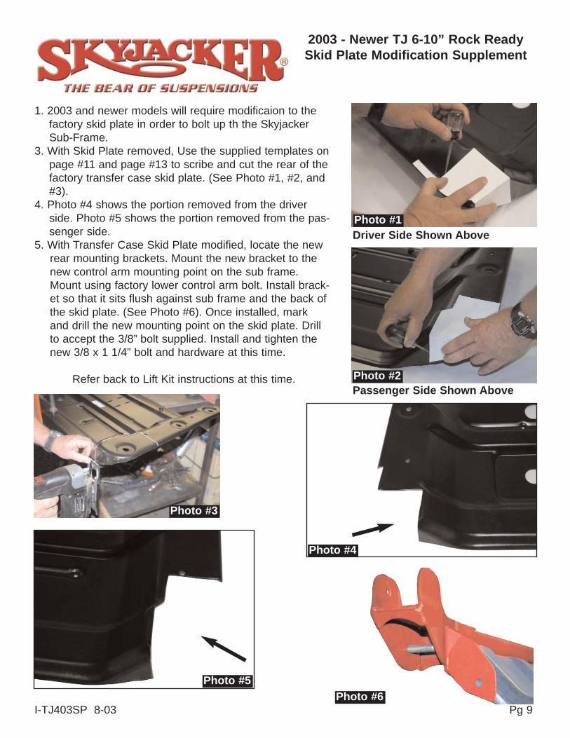
1. 2003 and newer models will require modificaion to thefactory skid plate in order to bolt up th the SkyjackerSub-Frame.
3. With Skid Plate removed, Use the supplied templates onpage #11 and page #13 to scribe and cut the rear of thefactory transfer case skid plate. (See Photo #1, #2, and#3).
4. Photo #4 shows the portion removed from the driverside. Photo #5 shows the portion removed from the pas-senger side.
5. With Transfer Case Skid Plate modified, locate the newrear mounting brackets. Mount the new bracket to thenew control arm mounting point on the sub frame.Mount using factory lower control arm bolt. Install brack-et so that it sits flush against sub frame and the back ofthe skid plate. (See Photo #6). Once installed, markand drill the new mounting point on the skid plate. Drillto accept the 3/8” bolt supplied. Install and tighten thenew 3/8 x 1 1/4” bolt and hardware at this time.
Refer back to Lift Kit instructions at this time.
Photo #1Driver Side Shown Above
Passenger Side Shown AbovePhoto #2
Photo #3
Photo #4
Photo #5
Pg 9I-TJ403SP 8-03Photo #6

Pg 10
Pg 11
2003Rubicon/Wrangler
Skid Plate ModificationTemplate
(Driver Side)

Pg 12
Pg 13
2003Rubicon/Wrangler
Skid Plate ModificationTemplate
(Passenger Side)
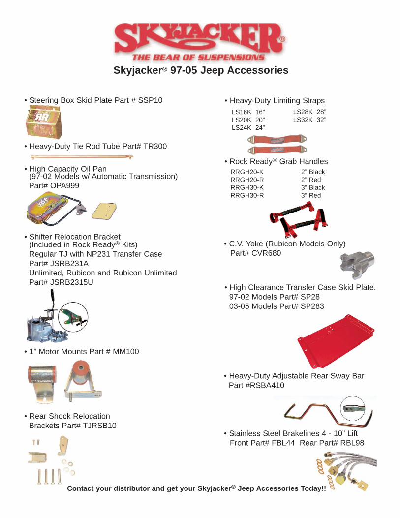
Skyjacker® 97-05 Jeep Accessories
• Steering Box Skid Plate Part # SSP10
• Heavy-Duty Tie Rod Tube Part# TR300
• High Capacity Oil Pan (97-02 Models w/ Automatic Transmission) Part# OPA999
• Shifter Relocation Bracket (Included in Rock Ready® Kits)Regular TJ with NP231 Transfer Case Part# JSRB231AUnlimited, Rubicon and Rubicon Unlimited Part# JSRB2315U
• 1” Motor Mounts Part # MM100
• Heavy-Duty Limiting Straps
• Rock Ready® Grab Handles
LS16K 16”LS20K 20”LS24K 24”
LS28K 28”LS32K 32”
RRGH20-K 2” BlackRRGH20-R 2” RedRRGH30-K 3” BlackRRGH30-R 3” Red
• High Clearance Transfer Case Skid Plate.97-02 Models Part# SP2803-05 Models Part# SP283
• C.V. Yoke (Rubicon Models Only) Part# CVR680
• Heavy-Duty Adjustable Rear Sway Bar Part #RSBA410
• Rear Shock Relocation Brackets Part# TJRSB10
• Stainless Steel Brakelines 4 - 10” LiftFront Part# FBL44 Rear Part# RBL98
Contact your distributor and get your Skyjacker® Jeep Accessories Today!!