Embed Size (px)
Citation preview
K6859768 10/10/2007 Page 1 of 15
BACKUP CAMERA KITJEEP GRAND CHEROKEE
INSTALLATION INSTRUCTIONS
Read entire instructions thoroughly before starting. TOOLS REQUIRED:
• Hook Tool • Phillips screwdriver • T10, T20 Torx drivers • Socket wrench with extension • 10,16mm Socket • Scissors • Small Saw • File • Solder • Soldering Iron • 5/8” Hole Saw• Drill • 1/8” Drill Bit • 3/8” Drill Bit • Electrical Tape • Wire Stripper
CONTENTS:
2
1
6
11
10
5
9
Item Qty. Description
1 Template
1 Camera
2 Screw
2 Nut 1 Camera Extension Harness
12-15 Short Tie Strap
1 T-Harness
1 Monitor
1 Module
1 Foam Tape
3-5 Long Tie Strap 1 Mounting Plate
2 Mounting Screws
1
2
7
8
3
4
5
6
7
8
9
10
11
12
13
3
4
1312
EN
K6859768 10/10/2007 Page 2 of 15
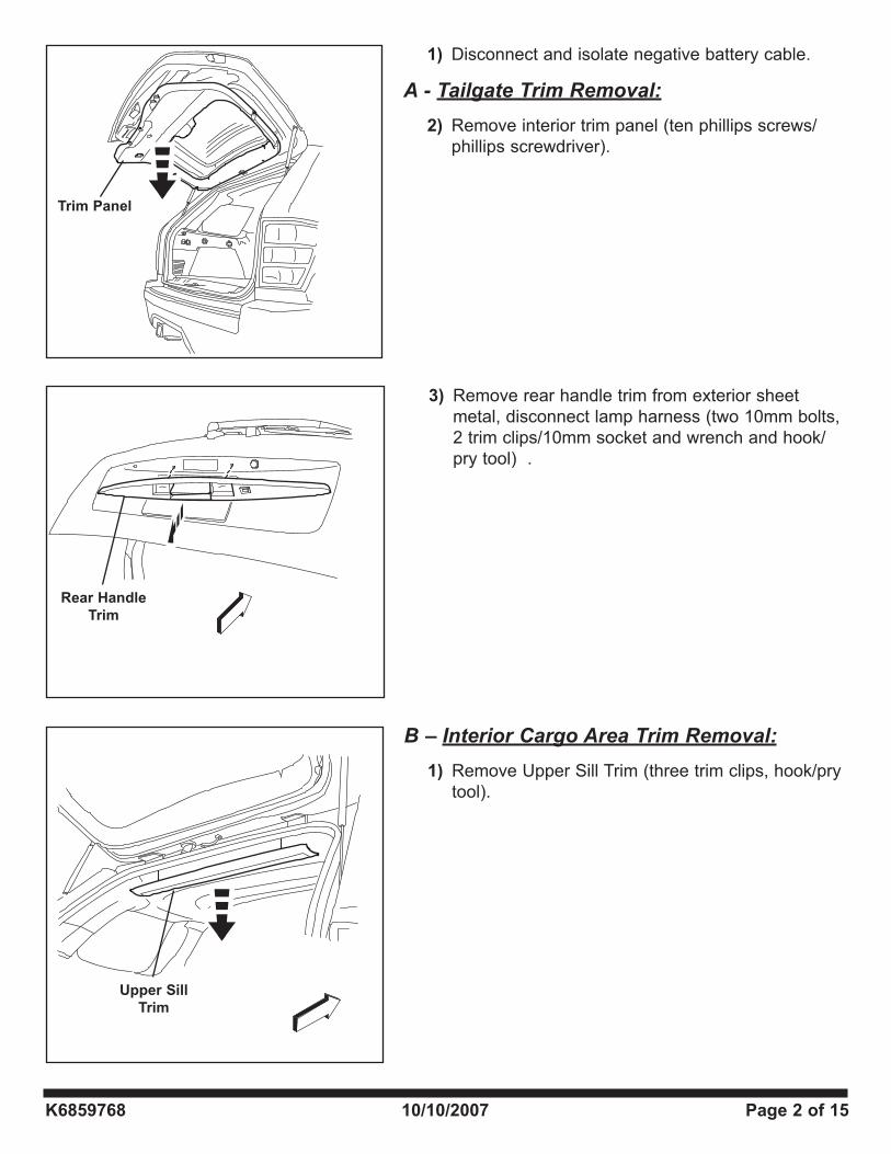
1) Disconnect and isolate negative battery cable.
A - Tailgate Trim Removal:
2) Remove interior trim panel (ten phillips screws/phillips screwdriver).
3) Remove rear handle trim from exterior sheet metal, disconnect lamp harness (two 10mm bolts, 2 trim clips/10mm socket and wrench and hook/pry tool) .
B – Interior Cargo Area Trim Removal:
1) Remove Upper Sill Trim (three trim clips, hook/pry tool).
Trim Panel
Rear Handle
Trim
Upper Sill
Trim
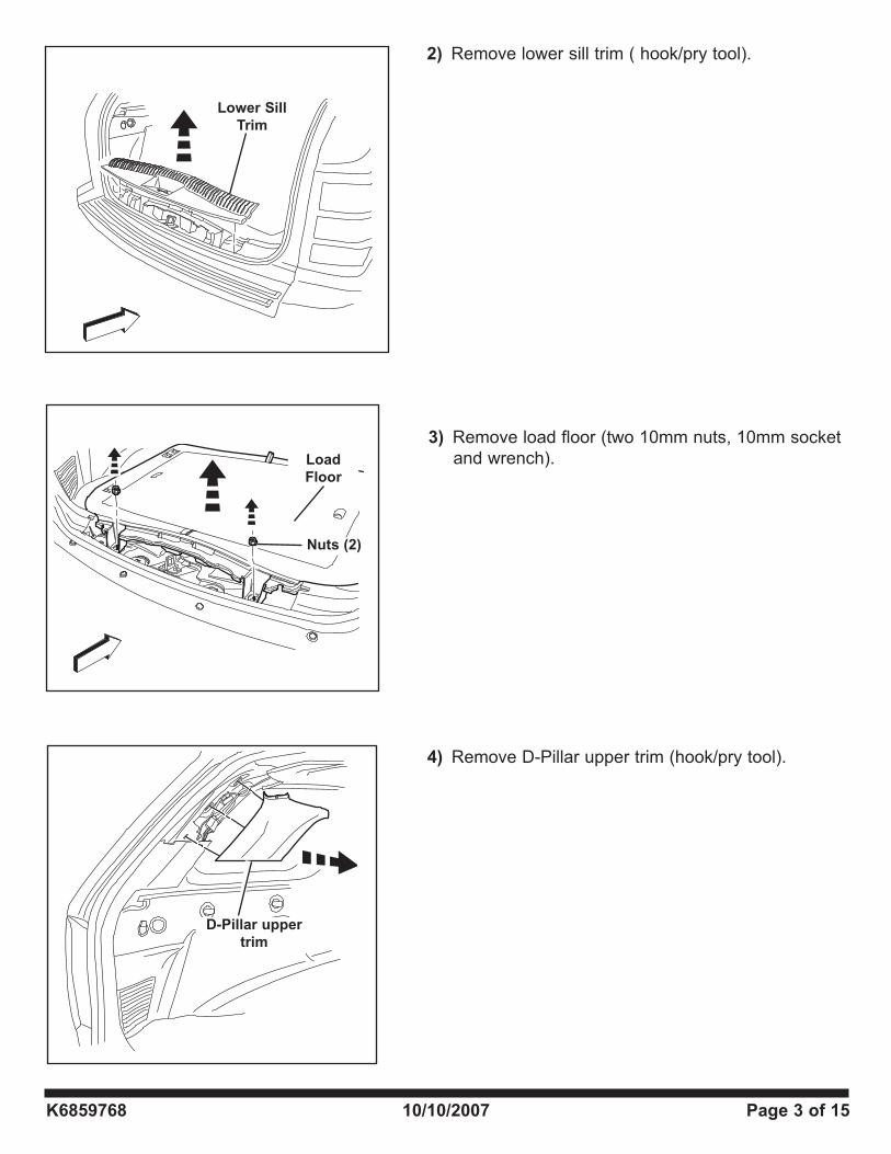
2) Remove lower sill trim ( hook/pry tool).
K6859768 10/10/2007 Page 3 of 15
3) Remove load floor (two 10mm nuts, 10mm socket and wrench).
4) Remove D-Pillar upper trim (hook/pry tool).
D-Pillar upper
trim
Load
Floor
Lower Sill
Trim
Nuts (2)
K6859768 10/10/2007 Page 4 of 15
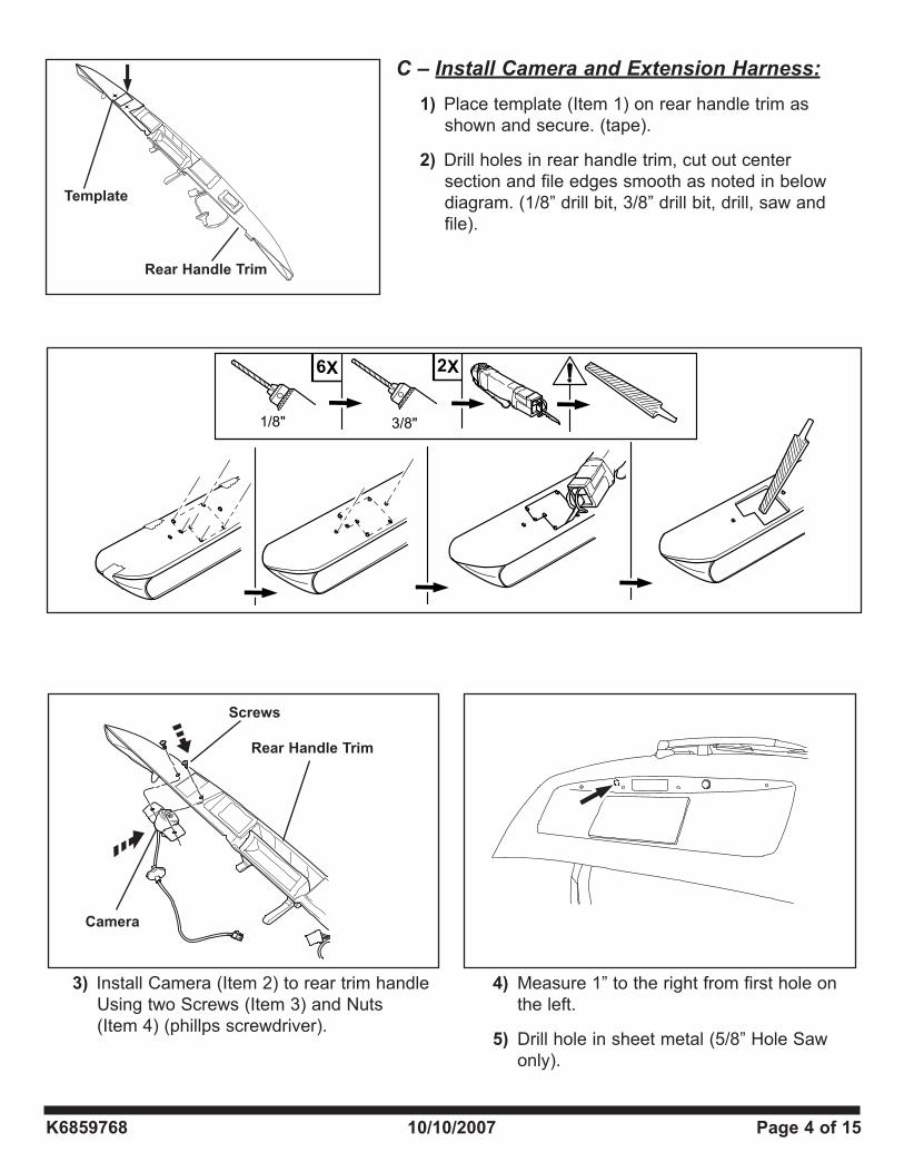
Template
Rear Handle Trim
Camera
Rear Handle Trim
3) Install Camera (Item 2) to rear trim handle Using two Screws (Item 3) and Nuts (Item 4) (phillps screwdriver).
Screws
4) Measure 1” to the right from first hole on the left.
5) Drill hole in sheet metal (5/8” Hole Saw only).
C – Install Camera and Extension Harness:
1) Place template (Item 1) on rear handle trim as shown and secure. (tape).
2) Drill holes in rear handle trim, cut out center section and file edges smooth as noted in below diagram. (1/8” drill bit, 3/8” drill bit, drill, saw and file).
K6859768 10/10/2007 Page 5 of 15
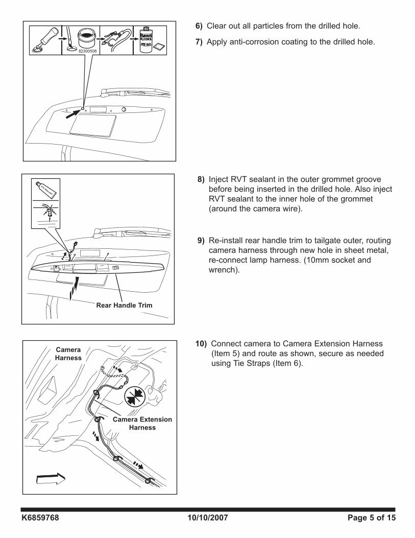
10) Connect camera to Camera Extension Harness (Item 5) and route as shown, secure as needed using Tie Straps (Item 6).
Camera
Harness
Rear Handle Trim
Camera Extension
Harness
82300508
8) Inject RVT sealant in the outer grommet groove before being inserted in the drilled hole. Also inject RVT sealant to the inner hole of the grommet (around the camera wire).
9) Re-install rear handle trim to tailgate outer, routing camera harness through new hole in sheet metal, re-connect lamp harness. (10mm socket and wrench).
6) Clear out all particles from the drilled hole.
7) Apply anti-corrosion coating to the drilled hole.
K6859768 10/10/2007 Page 6 of 15
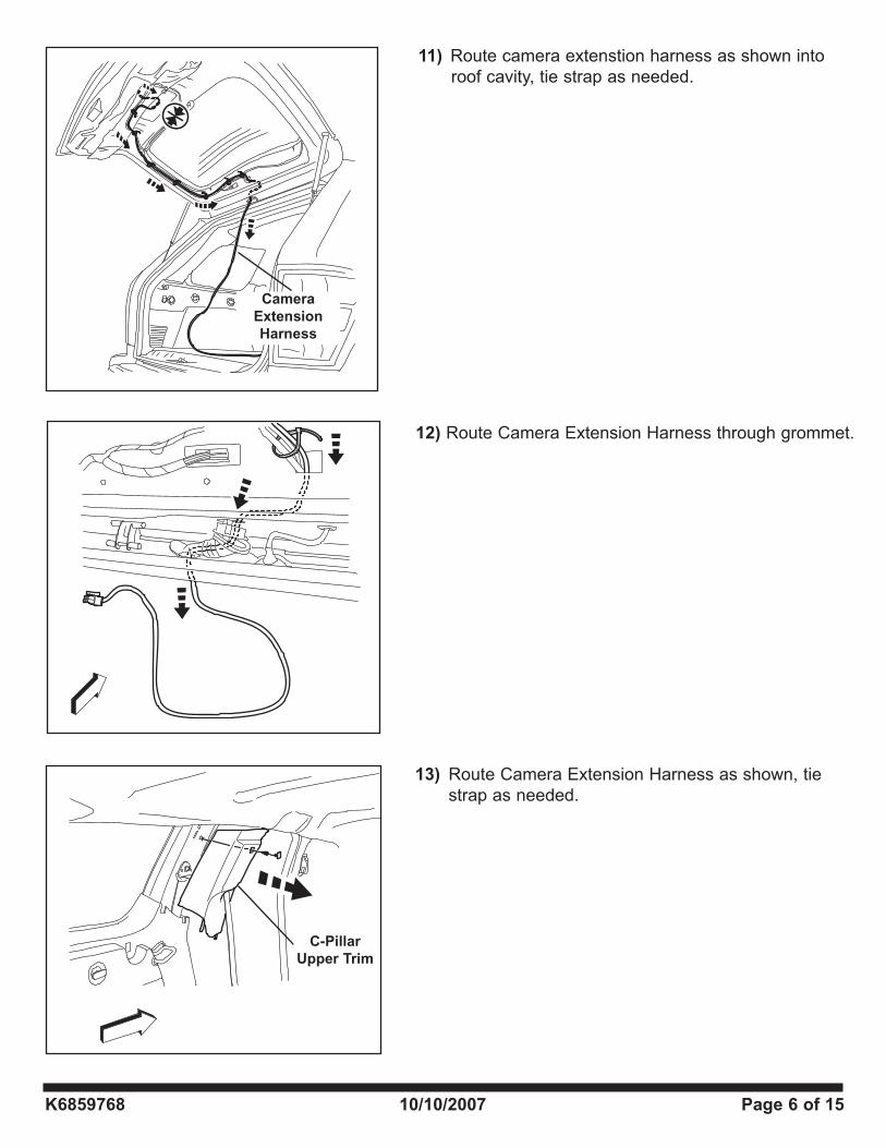
13) Route Camera Extension Harness as shown, tie strap as needed.
C-Pillar
Upper Trim
12) Route Camera Extension Harness through grommet.
11) Route camera extenstion harness as shown into roof cavity, tie strap as needed.
Camera
Extension
Harness
K6859768 10/10/2007 Page 7 of 15
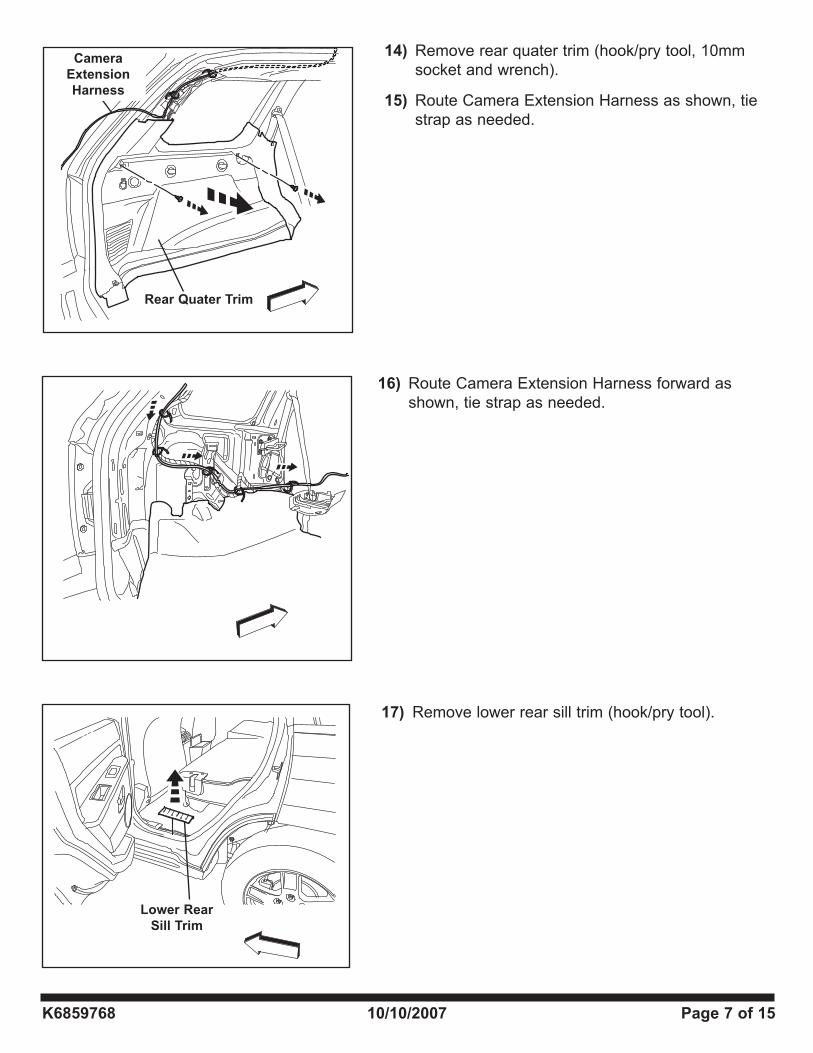
16) Route Camera Extension Harness forward as shown, tie strap as needed.
17) Remove lower rear sill trim (hook/pry tool).
Lower Rear
Sill Trim
14) Remove rear quater trim (hook/pry tool, 10mm socket and wrench).
15) Route Camera Extension Harness as shown, tie strap as needed.
Rear Quater Trim
Camera
Extension
Harness
K6859768 10/10/2007 Page 8 of 15
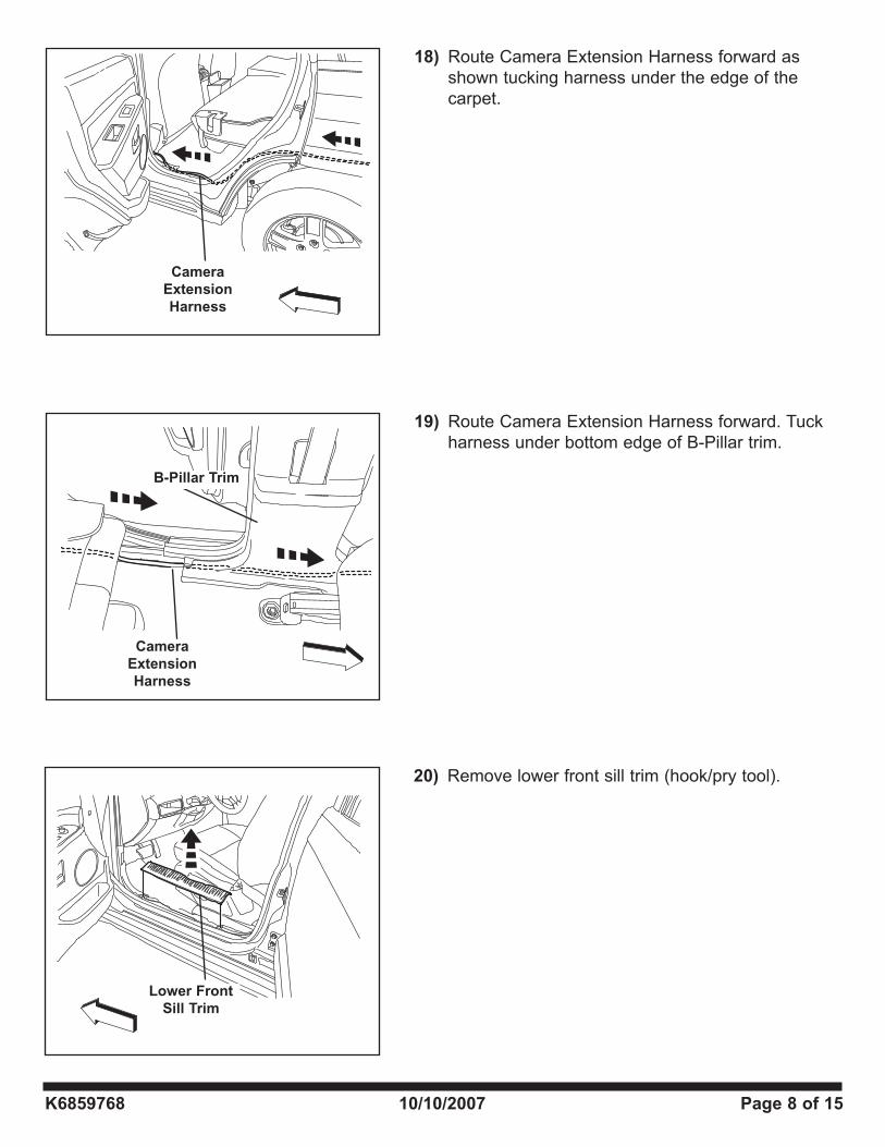
20) Remove lower front sill trim (hook/pry tool).
Lower Front
Sill Trim
19) Route Camera Extension Harness forward. Tuck harness under bottom edge of B-Pillar trim.
Camera
Extension
Harness
B-Pillar Trim
18) Route Camera Extension Harness forward as shown tucking harness under the edge of the carpet.
Camera
Extension
Harness
K6859768 10/10/2007 Page 9 of 15
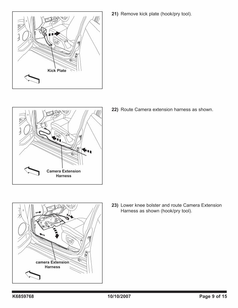
21) Remove kick plate (hook/pry tool).
Kick Plate
22) Route Camera extension harness as shown.
Camera Extension
Harness
23) Lower knee bolster and route Camera Extension Harness as shown (hook/pry tool).
camera Extension
Harness
K6859768 10/10/2007 Page 10 of 15
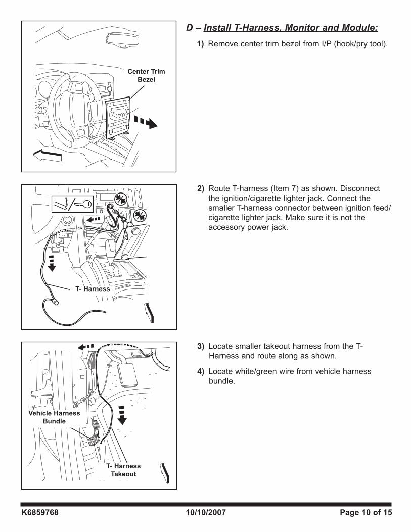
3) Locate smaller takeout harness from the T- Harness and route along as shown.
4) Locate white/green wire from vehicle harness bundle.
T- Harness
Takeout
Vehicle Harness
Bundle
2) Route T-harness (Item 7) as shown. Disconnect the ignition/cigarette lighter jack. Connect the smaller T-harness connector between ignition feed/cigarette lighter jack. Make sure it is not the accessory power jack.
T- Harness
D – Install T-Harness, Monitor and Module:
1) Remove center trim bezel from I/P (hook/pry tool).
Center Trim
Bezel
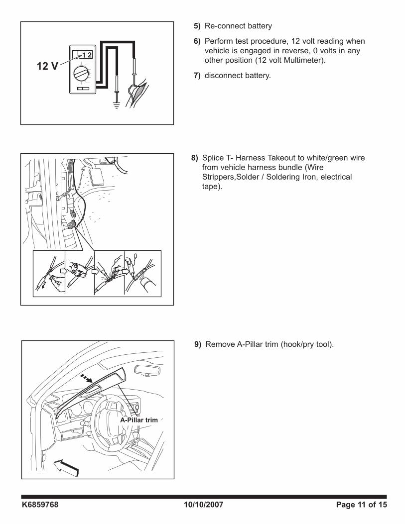
9) Remove A-Pillar trim (hook/pry tool).
A-Pillar trim
K6859768 10/10/2007 Page 11 of 15
5) Re-connect battery
6) Perform test procedure, 12 volt reading when vehicle is engaged in reverse, 0 volts in any other position (12 volt Multimeter).
7) disconnect battery.12 V
8) Splice T- Harness Takeout to white/green wire from vehicle harness bundle (Wire Strippers,Solder / Soldering Iron, electrical tape).
K6859768 10/10/2007 Page 12 of 15
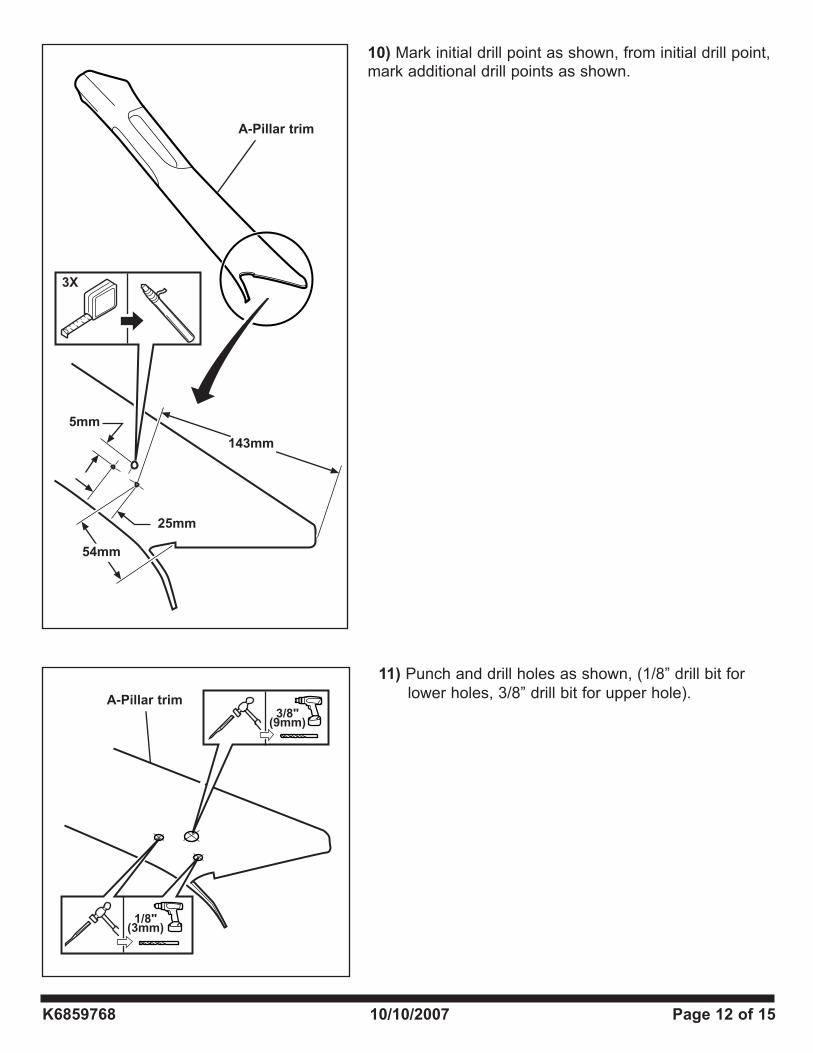
11) Punch and drill holes as shown, (1/8” drill bit for lower holes, 3/8” drill bit for upper hole).
3/8"(9mm)
1/8"(3mm)
10) Mark initial drill point as shown, from initial drill point, mark additional drill points as shown.
5mm
143mm
54mm
25mm
3X
A-Pillar trim
A-Pillar trim
K6859768 10/10/2007 Page 13 of 15
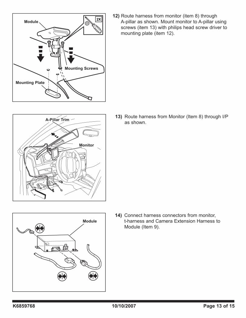
14) Connect harness connectors from monitor, t-harness and Camera Extension Harness to Module (Item 9).
13) Route harness from Monitor (Item 8) through I/P as shown.
12) Route harness from monitor (item 8) through A-pillar as shown. Mount monitor to A-pillar using screws (item 13) with philips head screw driver to mounting plate (item 12).
2X
Module
Monitor
A-Pillar Trim
Mounting Plate
Module
Mounting Screws
K6859768 10/10/2007 Page 14 of 15
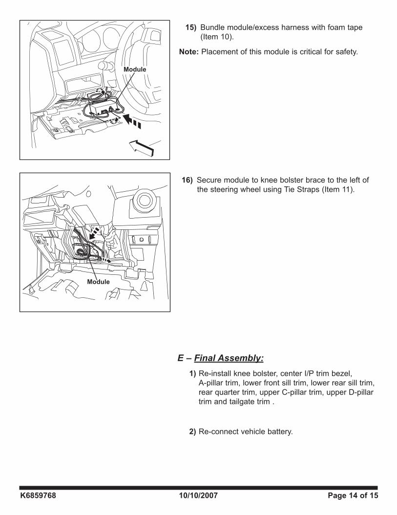
15) Bundle module/excess harness with foam tape (Item 10).
Note: Placement of this module is critical for safety.
16) Secure module to knee bolster brace to the left of the steering wheel using Tie Straps (Item 11).
E – Final Assembly:
1) Re-install knee bolster, center I/P trim bezel, A-pillar trim, lower front sill trim, lower rear sill trim, rear quarter trim, upper C-pillar trim, upper D-pillar trim and tailgate trim .
2) Re-connect vehicle battery.
Module
Module
K6859768 10/10/2007 Page 15 of 15
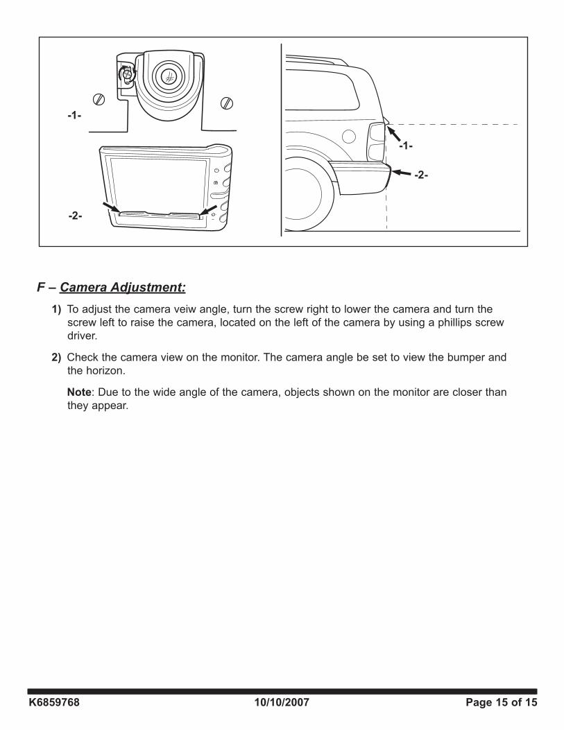
F – Camera Adjustment:
1) To adjust the camera veiw angle, turn the screw right to lower the camera and turn the screw left to raise the camera, located on the left of the camera by using a phillips screw driver.
2) Check the camera view on the monitor. The camera angle be set to view the bumper and the horizon.
Note: Due to the wide angle of the camera, objects shown on the monitor are closer than they appear.