Embed Size (px)
Citation preview

ALUMINUM ELECTROLYTIC CAPACITORS
v2019.1
ALUMINUM ELECTROLYTIC CAPACITORS · RADIAL TYPE
CD 263 BK SERIES
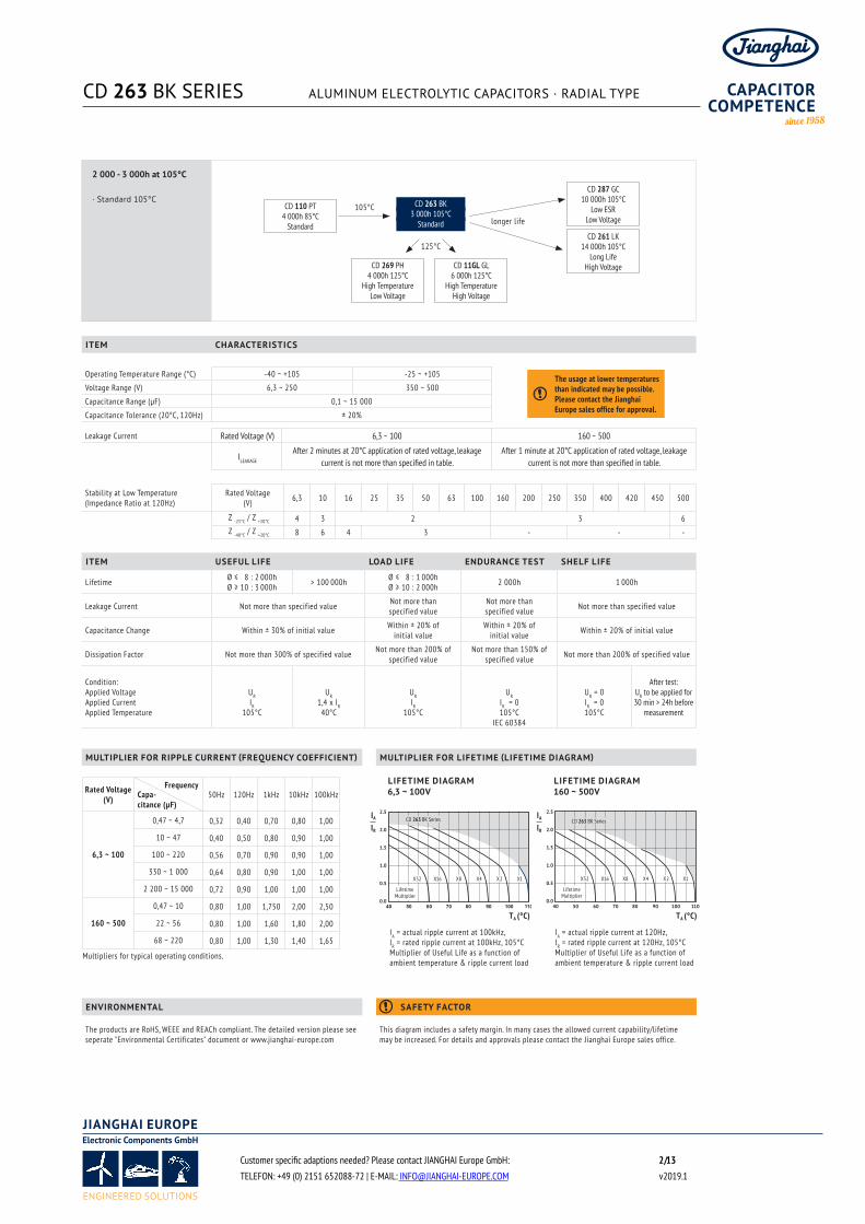
CD 263 BK SERIES ALUMINUM ELECTROLYTIC CAPACITORS · RADIAL TYPE
Customer specific adaptions needed? Please contact JIANGHAI Europe GmbH: / 2 13TELEFON: +49 (0) 2151 652088-72 | E-MAIL: [email protected] v2019.1
2 000 - 3 000h at 105°C
· Standard 105°C
ITEM USEFUL LIFE LOAD LIFE ENDURANCE TEST SHELF LIFE
Lifetime Ø ≤ 08 : 2 000hØ ≥ 10 : 3 000h > 100 000h Ø ≤ 08 : 1 000h
Ø ≥ 10 : 2 000h 2 000h 1 000h
Leakage Current Not more than specified value Not more than specified value
Not more than specified value Not more than specified value
Capacitance Change Within ± 30% of initial value Within ± 20% of initial value
Within ± 20% of initial value Within ± 20% of initial value
Dissipation Factor Not more than 300% of specified value Not more than 200% of specified value
Not more than 150% of specified value Not more than 200% of specified value
Condition:Applied VoltageApplied CurrentApplied Temperature
URIR
105°C
UR1,4 x IR
40°C
URIR
105°C
URIR = 0105°C
IEC 60384
UR = 0IR = 0105°C
After test: UR to be applied for 30 min > 24h before
measurement
ITEM CHARACTERISTICS
Operating Temperature Range (°C) -40 ~ +105 -25 ~ +105
Voltage Range (V) 6,3 ~ 250 350 ~ 500
Capacitance Range (µF) 0,1 ~ 15 000
Capacitance Tolerance (20°C, 120Hz) ± 20%
Leakage Current Rated Voltage (V) 6,3 ~ 100 160 ~ 500
ILEAKAGE
After 2 minutes at 20°C application of rated voltage, leakage current is not more than specified in table.
After 1 minute at 20°C application of rated voltage, leakage current is not more than specified in table.
IA = actual ripple current at 100kHz, IR = rated ripple current at 100kHz, 105°C Multiplier of Useful Life as a function of ambient temperature & ripple current load
Rated Voltage (V) 50Hz 120Hz 1kHz 10kHz 100kHz
6,3 ~ 100
0,47 ~ 4,7 0,32 0,40 0,70 0,80 1,00
10 ~ 47 0,40 0,50 0,80 0,90 1,00
100 ~ 220 0,56 0,70 0,90 0,90 1,00
330 ~ 1 000 0,64 0,80 0,90 1,00 1,00
2 200 ~ 15 000 0,72 0,90 1,00 1,00 1,00
160 ~ 500
0,47 ~ 10 0,80 1,00 1,750 2,00 2,50
22 ~ 56 0,80 1,00 1,60 1,80 2,00
68 ~ 220 0,80 1,00 1,30 1,40 1,65
Multipliers for typical operating conditions.
IA
IR
TA (°C)
Stability at Low Temperature (Impedance Ratio at 120Hz)
Rated Voltage(V) 6,3 10 16 25 35 50 63 100 160 200 250 350 400 420 450 500
Z -25°C / Z +20°C 4 3 2 3 6 Z -40°C / Z +20°C 8 6 4 3 - - -
FrequencyCapa-citance (µF)
40 50 60 70 80 90 100 110
2.5
2.0
1.5
1.0
0.5
0.0
X32 X16 X8 X4 X2 X1
LifetimeMultiplier
CD 263 BK Series
40 50 60 70 80 90 100 110
2.5
2.0
1.5
1.0
0.5
0.0
X32 X16 X8 X4 X2 X1
LifetimeMultiplier
CD 263 BK Series
LIFETIME DIAGRAM6,3 ~ 100V
LIFETIME DIAGRAM160 ~ 500V
IA
IR
TA (°C)
IA = actual ripple current at 120Hz, IR = rated ripple current at 120Hz, 105°C Multiplier of Useful Life as a function of ambient temperature & ripple current load
CD 287 GC10 000h 105°C
Low ESRLow Voltagelonger life
105°C
CD 261 LK14 000h 105°C
Long LifeHigh Voltage
CD 110 PT4 000h 85°C
Standard
CD 263 BK3 000h 105°C
Standard
CD 269 PH4 000h 125°C
High TemperatureLow Voltage
CD 11GL GL6 000h 125°C
High TemperatureHigh Voltage
125°C
The usage at lower temperatures than indicated may be possible. Please contact the Jianghai Europe sales office for approval.
l
ENVIRONMENTAL SAFETY FACTOR
The products are RoHS, WEEE and REACh compliant. The detailed version please see seperate "Environmental Certificates" document or www.jianghai-europe.com
This diagram includes a safety margin. In many cases the allowed current capability/lifetime may be increased. For details and approvals please contact the Jianghai Europe sales office.
l
MULTIPLIER FOR RIPPLE CURRENT (FREQUENCY COEFFICIENT) MULTIPLIER FOR LIFETIME (LIFETIME DIAGRAM)

CD 263 BK SERIES ALUMINUM ELECTROLYTIC CAPACITORS · RADIAL TYPE
Customer specific adaptions needed? Please contact JIANGHAI Europe GmbH: / 3 13TELEFON: +49 (0) 2151 652088-72 | E-MAIL: [email protected] v2019.1
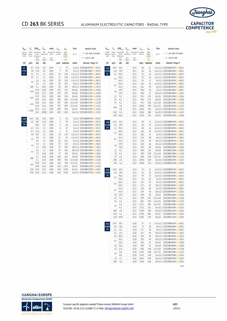
6,3(7,2)
0J
33 8,9 2,5 0,22 3 105 5 x11,5 ECR0JBK330M◊◊∆∆051147 6,3 1,5 0,22 3 120 5 x11,5 ECR0JBK470M◊◊∆∆0511
100 3,0 1,2 0,22 7 130 5 x11,5 ECR0JBK101M◊◊∆∆0511
2201,4 1,2 0,22 14 180 5 x11,5 ECR0JBK221M◊◊∆∆05111,4 0,87 0,22 14 180 6,3 x11,5 ECR0JBK221M◊◊∆∆0611
330 0,89 0,58 0,22 21 220 6,3 x11,5 ECR0JBK331M◊◊∆∆0611
4700,63 0,55 0,22 30 250 6,3 x11,5 ECR0JBK471M◊◊∆∆06110,63 0,39 0,22 30 315 8 x11,5 ECR0JBK471M◊◊∆∆0811
1 0000,30 0,37 0,22 63 435 8 x11,5 ECR0JBK102M◊◊∆∆08110,30 0,23 0,22 63 500 10 x12,5 ECR0JBK102M◊◊∆∆1012
2 2000,15 0,095 0,24 139 765 10 x20 ECR0JBK222M◊◊∆∆10200,15 0,095 0,24 139 1000 12,5 x20 ECR0JBK222M◊◊∆∆1220
3 3000,11 0,12 0,26 208 882 10 x20 ECR0JBK332M◊◊∆∆10200,11 0,090 0,26 208 1050 12,5 x20 ECR0JBK332M◊◊∆∆1220
4 7000,080 0,090 0,28 297 1120 12,5 x20 ECR0JBK472M◊◊∆∆12200,080 0,061 0,28 297 1670 16 x25 ECR0JBK472M◊◊∆∆1625
68000,063 0,090 0,32 429 1380 12,5 x20 ECR0JBK682M◊◊∆∆12200,063 0,056 0,32 429 1740 16 x25 ECR0JBK682M◊◊∆∆1625
1 00000,054 0,045 0,40 630 2110 16 x31,5 ECR0JBK103M◊◊∆∆16310,054 0,061 0,40 630 1750 16 x25 ECR0JBK103M◊◊∆∆1625
15 0000,045 0,042 0,50 945 2040 16 x35,5 ECR0JBK153M◊◊∆∆16350,045 0,036 0,50 945 2580 18 x35,5 ECR0JBK153M◊◊∆∆1835
10(13)1A
22 11,5 2,5 0,19 3 92 5 x11,5 ECR1ABK220M◊◊∆∆051133 7,7 1,9 0,19 4 105 5 x11,5 ECR1ABK330M◊◊∆∆051147 5,4 1,5 0,19 5 120 5 x11,5 ECR1ABK470M◊◊∆∆0511
100 2,6 1,2 0,19 10 130 5 x11,5 ECR1ABK101M◊◊∆∆0511220 1,2 0,58 0,19 22 220 6,3 x11,5 ECR1ABK221M◊◊∆∆0611
3300,77 0,54 0,19 33 230 6,3 x11,5 ECR1ABK331M◊◊∆∆06110,77 0,47 0,19 33 265 8 x11,5 ECR1ABK331M◊◊∆∆0811
470 0,54 0,39 0,19 47 315 8 x11,5 ECR1ABK471M◊◊∆∆0811
1 0000,25 0,25 0,19 100 500 10 x12,5 ECR1ABK102M◊◊∆∆10120,25 0,18 0,19 100 615 10 x16 ECR1ABK102M◊◊∆∆1016
2 2000,13 0,17 0,21 220 761 10 x20 ECR1ABK222M◊◊∆∆10200,13 0,090 0,21 220 1050 12,5 x20 ECR1ABK222M◊◊∆∆1220
3 3000,10 0,086 0,23 330 1010 12,5 x20 ECR1ABK332M◊◊∆∆12200,10 0,068 0,23 330 1300 12,5 x25 ECR1ABK332M◊◊∆∆1225
4 7000,071 0,068 0,25 470 1250 12,5 x25 ECR1ABK472M◊◊∆∆12250,071 0,056 0,25 470 1740 16 x25 ECR1ABK472M◊◊∆∆1625
6 8000,057 0,056 0,29 680 1570 16 x25 ECR1ABK682M◊◊∆∆16250,057 0,045 0,29 680 2110 16 x31,5 ECR1ABK682M◊◊∆∆1631
1 00000,050 0,042 0,37 1000 1910 16 x35,5 ECR1ABK103M◊◊∆∆16350,050 0,036 0,37 1000 2580 18 x35,5 ECR1ABK103M◊◊∆∆1835
16(20)1C
10 21,3 2,5 0,16 3 92 5 x11,5 ECR1CBK100M◊◊∆∆051122 9,7 1,9 0,16 4 105 5 x11,5 ECR1CBK220M◊◊∆∆051133 6,5 1,5 0,16 6 120 5 x11,5 ECR1CBK330M◊◊∆∆051147 4,6 1,2 0,16 8 130 5 x11,5 ECR1CBK470M◊◊∆∆0511
1002,2 1,2 0,16 16 150 5 x11,5 ECR1CBK101M◊◊∆∆05112,2 0,58 0,16 16 220 6,3 x11,5 ECR1CBK101M◊◊∆∆0611
2201,0 0,54 0,16 36 250 6,3 x11,5 ECR1CBK221M◊◊∆∆06111,0 0,47 0,16 36 290 8 x11,5 ECR1CBK221M◊◊∆∆0811
330 0,65 0,39 0,16 53 315 8 x11,5 ECR1CBK331M◊◊∆∆0811
4700,46 0,66 0,16 76 350 8 x11,5 ECR1CBK471M◊◊∆∆08110,46 0,23 0,16 76 500 10 x12,5 ECR1CBK471M◊◊∆∆1012
1 0000,22 0,21 0,16 160 610 10 x16 ECR1CBK102M◊◊∆∆10160,22 0,12 0,16 160 825 10 x20 ECR1CBK102M◊◊∆∆1020
2 2000,11 0,095 0,18 352 961 12,5 x20 ECR1CBK222M◊◊∆∆12200,11 0,068 0,18 352 1300 12,5 x25 ECR1CBK222M◊◊∆∆1225
3 3000,081 0,068 0,20 528 1 200 12,5 x25 ECR1CBK332M◊◊∆∆12250,081 0,056 0,20 528 1740 16 x25 ECR1CBK332M◊◊∆∆1625
4 7000,063 0,052 0,22 752 1490 16 x25 ECR1CBK472M◊◊∆∆16250,063 0,045 0,22 752 2110 16 x31,5 ECR1CBK472M◊◊∆∆1631
6 8000,051 0,042 0,26 1088 1830 16 x35,5 ECR1CBK682M◊◊∆∆16350,051 0,036 0,26 1088 2580 18 x35,5 ECR1CBK682M◊◊∆∆1835
25(32)1E
4,7 39,6 3,0 0,14 3 85 5 x11,5 ECR1EBK4R7M◊◊∆∆051110 18,6 2,5 0,14 3 92 5 x11,5 ECR1EBK100M◊◊∆∆051122 8,5 1,9 0,14 6 105 5 x11,5 ECR1EBK220M◊◊∆∆051133 5,7 1,5 0,14 9 120 5 x11,5 ECR1EBK330M◊◊∆∆051147 4,0 1,2 0,14 12 130 5 x11,5 ECR1EBK470M◊◊∆∆0511
100 1,9 0,58 0,14 25 220 6,3 x11,5 ECR1EBK101M◊◊∆∆0611220 0,85 0,39 0,14 55 315 8 x11,5 ECR1EBK221M◊◊∆∆0811330 0,57 0,23 0,14 83 500 10 x12,5 ECR1EBK331M◊◊∆∆1012
4700,40 0,21 0,14 118 429 10 x12,5 ECR1EBK471M◊◊∆∆10120,40 0,18 0,14 118 615 10 x16 ECR1EBK471M◊◊∆∆1016
1 0000,19 0,12 0,14 250 705 10 x20 ECR1EBK102M◊◊∆∆10200,19 0,090 0,14 250 1050 12,5 x20 ECR1EBK102M◊◊∆∆1220
2 200 0,10 0,056 0,16 550 1740 16 x25 ECR1EBK222M◊◊∆∆1625
3 3000,073 0,056 0,18 825 1440 16 x25 ECR1EBK332M◊◊∆∆16250,073 0,045 0,18 825 2110 16 x31,5 ECR1EBK332M◊◊∆∆1631
4 7000,057 0,050 0,20 1175 1880 16 x31,5 ECR1EBK472M◊◊∆∆16310,057 0,036 0,20 1175 2580 18 x35,5 ECR1EBK472M◊◊∆∆1835
35(44)1V
4,7 33,9 2,5 0,12 3 92 5 x11,5 ECR1VBK4R7M◊◊∆∆051110 16,0 1,8 0,12 4 105 5 x11,5 ECR1VBK100M◊◊∆∆051122 7,3 1,5 0,12 8 120 5 x11,5 ECR1VBK220M◊◊∆∆051133 4,9 1,5 0,12 12 130 5 x11,5 ECR1VBK330M◊◊∆∆0511
473,4 1,7 0,12 17 90 5 x11,5 ECR1VBK470M◊◊∆∆05113,4 0,58 0,12 17 220 6,3 x11,5 ECR1VBK470M◊◊∆∆0611
1001,6 0,80 0,12 35 151 6,3 x11,5 ECR1VBK101M◊◊∆∆06111,6 0,39 0,12 35 315 8 x11,5 ECR1VBK101M◊◊∆∆0811
220 0,73 0,23 0,12 77 500 10 x12,5 ECR1VBK221M◊◊∆∆1012
3300,49 0,25 0,12 116 384 10 x12,5 ECR1VBK331M◊◊∆∆10120,49 0,18 0,12 116 615 10 x16 ECR1VBK331M◊◊∆∆1016
4700,34 0,21 0,12 165 470 10 x16 ECR1VBK471M◊◊∆∆10160,34 0,12 0,12 165 825 10 x20 ECR1VBK471M◊◊∆∆1020
1 0000,16 0,095 0,12 350 857 12,5 x20 ECR1VBK102M◊◊∆∆12200,16 0,068 0,12 350 1300 12,5 x25 ECR1VBK102M◊◊∆∆1225
2 2000,085 0,056 0,14 770 1380 16 x25 ECR1VBK222M◊◊∆∆16250,085 0,045 0,14 770 2110 16 x31,5 ECR1VBK222M◊◊∆∆1631
3 3000,065 0,042 0,16 1155 1780 16 x35,5 ECR1VBK332M◊◊∆∆16350,065 0,036 0,16 1155 2580 18 x35,5 ECR1VBK332M◊◊∆∆1835
4 700 0,051 0,036 0,18 1645 2120 18 x35,5 ECR1VBK472M◊◊∆∆1835
50(63)1H
0,10 1.327 18,0 0,10 3 10 5 x11,5 ECR1HBK0R1M◊◊∆∆05110,22 603 13,0 0,10 3 15 5 x11,5 ECR1HBKR22M◊◊∆∆05110,33 402 10,0 0,10 3 18 5 x11,5 ECR1HBKR33M◊◊∆∆05110,47 283 7,0 0,10 3 23 5 x11,5 ECR1HBKR47M◊◊∆∆0511
1,0 133 4,9 0,10 3 35 5 x11,5 ECR1HBK010M◊◊∆∆05112,2 60,3 4,2 0,10 3 53 5 x11,5 ECR1HBK2R2M◊◊∆∆05113,3 40,2 3,9 0,10 3 65 5 x11,5 ECR1HBK3R3M◊◊∆∆05114,7 28,3 3,6 0,10 3 82 5 x11,5 ECR1HBK4R7M◊◊∆∆051110 13,3 2,7 0,10 5 100 5 x11,5 ECR1HBK100M◊◊∆∆051122 6,1 1,9 0,10 11 125 5 x11,5 ECR1HBK220M◊◊∆∆0511
334,1 1,9 0,10 17 90 5 x11,5 ECR1HBK330M◊◊∆∆05114,1 1,1 0,10 17 195 6,3 x11,5 ECR1HBK330M◊◊∆∆0611
47 2,9 0,90 0,10 24 245 6,3 x11,5 ECR1HBK470M◊◊∆∆0611100 1,4 0,50 0,10 50 385 8 x11,5 ECR1HBK101M◊◊∆∆0811
2200,61 0,38 0,10 110 314 10 x12,5 ECR1HBK221M◊◊∆∆10120,61 0,27 0,10 110 505 10 x16 ECR1HBK221M◊◊∆∆1016
3300,41 0,27 0,10 165 421 10 x16 ECR1HBK331M◊◊∆∆10160,41 0,18 0,10 165 675 10 x20 ECR1HBK331M◊◊∆∆1020
470 0,29 0,12 0,10 235 895 12,5 x20 ECR1HBK471M◊◊∆∆12201 000 0,14 0,076 0,10 500 1495 16 x25 ECR1HBK102M◊◊∆∆1625
2 2000,073 0,065 0,12 1100 1660 16 x35,5 ECR1HBK222M◊◊∆∆16350,073 0,050 0,12 1100 2190 18 x35,5 ECR1HBK222M◊◊∆∆1835
>>
URDC CR ESRmax Zmax tanб Ileak IRAC Size O R D E R CO D E
(SurgeVoltage)
Code
Rated Capaci-tance
Equivalent Series
Resistance20°C
120Hz
MaxImpedance
20°C100kHz
Dissipation Factor
20°C120Hz
Leakage Current
Rated Ripple Current 105°C
100kHz
øD x L ◊◊= pin style & length
∆∆= pitch code
(V) (µF) (Ω) (Ω) (µA) (mArms) (mm) Details: Page 15
URDC CR ESRmax Zmax tanб Ileak IRAC Size O R D E R CO D E
(SurgeVoltage)
Code
Rated Capaci-tance
Equivalent Series
Resistance20°C
120Hz
MaxImpedance
20°C100kHz
Dissipation Factor
20°C120Hz
Leakage Current
Rated Ripple Current 105°C
100kHz
øD x L ◊◊= pin style & length
∆∆= pitch code
(V) (µF) (Ω) (Ω) (µA) (mArms) (mm) Details: Page 6
CD 263 BK SERIES ALUMINUM ELECTROLYTIC CAPACITORS · RADIAL TYPE
Customer specific adaptions needed? Please contact JIANGHAI Europe GmbH: / 4 13TELEFON: +49 (0) 2151 652088-72 | E-MAIL: [email protected] v2019.1
63(79)
1J
4,7 25,4 5,8 0,09 3 74 5 x11,5 ECR1JBK4R7M◊◊∆∆051110 12,0 3,6 0,09 7 95 5 x11,5 ECR1JBK100M◊◊∆∆051122 5,5 2,1 0,09 14 130 6,3 x11,5 ECR1JBK220M◊◊∆∆061133 3,7 1,7 0,09 21 160 6,3 x11,5 ECR1JBK330M◊◊∆∆0611
472,6 1,8 0,09 30 120 6,3 x11,5 ECR1JBK470M◊◊∆∆06112,6 1,2 0,09 30 305 8 x11,5 ECR1JBK470M◊◊∆∆0811
100 1,2 0,65 0,09 63 395 10 x12,5 ECR1JBK101M◊◊∆∆1012
2200,55 0,48 0,09 139 335 10 x16 ECR1JBK221M◊◊∆∆10160,55 0,32 0,09 139 505 10 x20 ECR1JBK221M◊◊∆∆1020
3300,37 0,32 0,09 208 510 10 x20 ECR1JBK331M◊◊∆∆10200,37 0,22 0,09 208 660 12,5 x20 ECR1JBK331M◊◊∆∆1220
4700,26 0,16 0,09 297 640 12,5 x20 ECR1JBK471M◊◊∆∆12200,26 0,16 0,09 297 850 12,5 x25 ECR1JBK471M◊◊∆∆1225
1 0000,12 0,13 0,09 630 930 16 x25 ECR1JBK102M◊◊∆∆16250,12 0,098 0,09 630 1430 16 x31,5 ECR1JBK102M◊◊∆∆1631
100(125)
2A
0,47 226 13,0 0,08 3 30 5 x11,5 ECR2ABKR47M◊◊∆∆05111,0 107 11,0 0,08 3 45 5 x11,5 ECR2ABK010M◊◊∆∆0511
2A 48,3 9,2 0,08 3 60 5 x11,5 ECR2ABK2R2M◊◊∆∆05113,3 32,2 7,2 0,08 4 67 5 x11,5 ECR2ABK3R3M◊◊∆∆05114,7 22,6 6,3 0,08 5 75 5 x11,5 ECR2ABK4R7M◊◊∆∆051110 10,7 3,3 0,08 10 110 6,3 x11,5 ECR2ABK100M◊◊∆∆0611
224,9 3,5 0,08 22 93 6,3 x11,5 ECR2ABK220M◊◊∆∆06114,9 1,4 0,08 22 165 8 x11,5 ECR2ABK220M◊◊∆∆0811
333,3 1,5 0,08 33 130 8 x11,5 ECR2ABK330M◊◊∆∆08113,3 0,94 0,08 33 305 10 x12,5 ECR2ABK330M◊◊∆∆1012
472,3 1,1 0,08 47 165 10 x12,5 ECR2ABK470M◊◊∆∆10122,3 0,68 0,08 47 320 10 x16 ECR2ABK470M◊◊∆∆1016
1001,1 0,50 0,08 100 265 10 x20 ECR2ABK101M◊◊∆∆10201,1 0,28 0,08 100 585 12,5 x20 ECR2ABK101M◊◊∆∆1220
2200,49 0,22 0,08 220 440 12,5 x25 ECR2ABK221M◊◊∆∆12250,49 0,16 0,08 220 1120 16 x25 ECR2ABK221M◊◊∆∆1625
330 0,33 0,13 0,08 330 1290 16 x25 ECR2ABK331M◊◊∆∆1625470 0,23 0,11 0,08 470 1350 16 x31,5 ECR2ABK471M◊◊∆∆1631
160(200)
2C
0,47 424 - 0,15 48 12 6,3 x11,5 ECR2CBKR47M◊◊∆∆06111,0 199 - 0,15 56 18 6,3 x11,5 ECR2CBK010M◊◊∆∆06112,2 90,5 - 0,15 76 26 6,3 x11,5 ECR2CBK2R2M◊◊∆∆0611
3,360,3 - 0,15 93 28 6,3 x11,5 ECR2CBK3R3M◊◊∆∆061160,3 - 0,15 93 37 8 x11,5 ECR2CBK3R3M◊◊∆∆0811
4,742,4 - 0,15 116 34 6,3 x11,5 ECR2CBK4R7M◊◊∆∆061142,4 - 0,15 116 44 8 x11,5 ECR2CBK4R7M◊◊∆∆0811
1019,9 - 0,15 200 58 8 x11,5 ECR2CBK100M◊◊∆∆081119,9 - 0,15 200 75 10 x12,5 ECR2CBK100M◊◊∆∆1012
22 9,1 - 0,15 392 135 10 x16 ECR2CBK220M◊◊∆∆101633 6,1 - 0,15 568 175 10 x20 ECR2CBK330M◊◊∆∆102047 4,3 - 0,15 792 230 12,5 x20 ECR2CBK470M◊◊∆∆1220
1002,0 - 0,15 1640 299 12,5 x25 ECR2CBK101M◊◊∆∆12252,0 - 0,15 1640 330 16 x25,5 ECR2CBK101M◊◊∆∆1625
220 1,0 - 0,15 3560 500 16 x35,5 ECR2CBK221M◊◊∆∆1635330 0,61 - 0,15 5320 764 18 x36 ECR2CBK331M◊◊∆∆1836
200(250)
2D
0,47 424 - 0,15 50 12 6,3 x11,5 ECR2DBKR47M◊◊∆∆06111,0 199 - 0,15 60 18 6,3 x11,5 ECR2DBK010M◊◊∆∆06112,2 90,5 - 0,15 84 26 6,3 x11,5 ECR2DBK2R2M◊◊∆∆0611
3,360,3 - 0,15 106 28 6,3 x11,5 ECR2DBK3R3M◊◊∆∆061160,3 - 0,15 106 37 8 x11,5 ECR2DBK3R3M◊◊∆∆0811
4,742,4 - 0,15 134 40 8 x11,5 ECR2DBK4R7M◊◊∆∆081142,4 - 0,15 134 50 10 x12,5 ECR2DBK4R7M◊◊∆∆1012
1019,9 - 0,15 240 66 10 x12,5 ECR2DBK100M◊◊∆∆101219,9 - 0,15 240 80 10 x16 ECR2DBK100M◊◊∆∆1016
22 9,1 - 0,15 480 135 10 x20 ECR2DBK220M◊◊∆∆102033 6,1 - 0,15 700 190 12,5 x20 ECR2DBK330M◊◊∆∆122047 4,3 - 0,15 980 230 12,5 x25 ECR2DBK470M◊◊∆∆1225
100 2,0 - 0,15 2040 360 16 x25,5 ECR2DBK101M◊◊∆∆1625220 1,0 - 0,15 4440 525 18 x31,5 ECR2DBK221M◊◊∆∆1831
250(300)
2E
0,47 424 - 0,15 52 12 6,3 x11,5 ECR2EBKR47M◊◊∆∆06111,0 199 - 0,15 65 18 6,3 x11,5 ECR2EBK010M◊◊∆∆0611
2,290,5 - 0,15 95 23 6,3 x11,5 ECR2EBK2R2M◊◊∆∆061190,5 - 0,15 95 30 8 x11,5 ECR2EBK2R2M◊◊∆∆0811
3,360,3 - 0,15 123 43 8 x11,5 ECR2EBK3R3M◊◊∆∆081160,3 - 0,15 123 43 10 x12,5 ECR2EBK3R3M◊◊∆∆1012
4,742,4 - 0,15 158 40 8 x11,5 ECR2EBK4R7M◊◊∆∆081142,4 - 0,15 158 50 10 x12,5 ECR2EBK4R7M◊◊∆∆1012
10 19,9 - 0,15 290 90 10 x16 ECR2EBK100M◊◊∆∆101622 9,1 - 0,15 590 155 12,5 x20 ECR2EBK220M◊◊∆∆122033 6,1 - 0,15 865 190 12,5 x25 ECR2EBK330M◊◊∆∆1225
474,3 - 0,15 1215 205 12,5 x25 ECR2EBK470M◊◊∆∆12254,3 - 0,15 1215 225 16 x25,5 ECR2EBK470M◊◊∆∆1625
100 2,0 - 0,15 2540 340 16 x31,5 ECR2EBK101M◊◊∆∆1631150 1,3 - 0,15 3790 405 18 x25 ECR2EBK151M◊◊∆∆1825220 0,90 - 0,15 5540 570 18 x36 ECR2EBK221M◊◊∆∆1836
350(400)
2V
0,47 565 - 0,20 57 11 6,3 x11,5 ECR2VBKR47M◊◊∆∆06111,0 266 - 0,20 75 18 8 x11,5 ECR2VBK010M◊◊∆∆08112,2 121 - 0,20 117 30 8 x11,5 ECR2VBK2R2M◊◊∆∆08112,2 121 - 0,20 117 30 10 x12,5 ECR2VBK2R2M◊◊∆∆10123,3 80,4 - 0,20 156 36 10 x12,5 ECR2VBK3R3M◊◊∆∆1012
4,756,5 - 0,20 205 45 10 x12,5 ECR2VBK4R7M◊◊∆∆101256,5 - 0,20 205 47 10 x16 ECR2VBK4R7M◊◊∆∆1016
10 26,6 - 0,20 390 95 10 x20 ECR2VBK100M◊◊∆∆102022 12,1 - 0,20 810 130 12,5 x20 ECR2VBK220M◊◊∆∆1220
338,0 - 0,20 1195 180 12,5 x25 ECR2VBK330M◊◊∆∆12258,0 - 0,20 1195 160 16 x25,5 ECR2VBK330M◊◊∆∆1625
47 5,7 - 0,20 1685 330 16 x25,5 ECR2VBK470M◊◊∆∆1625100 3,0 - 0,20 3540 620 18 x31,5 ECR2VBK101M◊◊∆∆1831
URDC CR ESRmax Zmax tanб Ileak IRAC Size O R D E R CO D E
(SurgeVoltage)
Code
Rated Capaci-tance
Equivalent Series
Resistance20°C
120Hz
MaxImpedance
20°C100kHz
Dissipation Factor
20°C120Hz
Leakage Current
Rated Ripple Current 105°C120Hz
øD x L ◊◊= pin style & length
∆∆= pitch code
(V) (µF) (Ω) (Ω) (µA) (mArms) (mm) Details: Page 6
URDC CR ESRmax Zmax tanб Ileak IRAC Size O R D E R CO D E
(SurgeVoltage)
Code
Rated Capaci-tance
Equivalent Series
Resistance20°C
120Hz
MaxImpedance
20°C100kHz
Dissipation Factor
20°C120Hz
Leakage Current
Rated Ripple Current 105°C
100kHz
øD x L ◊◊= pin style & length
∆∆= pitch code
(V) (µF) (Ω) (Ω) (µA) (mArms) (mm) Details: Page 15
>>

CD 263 BK SERIES ALUMINUM ELECTROLYTIC CAPACITORS · RADIAL TYPE
Customer specific adaptions needed? Please contact JIANGHAI Europe GmbH: / 5 13TELEFON: +49 (0) 2151 652088-72 | E-MAIL: [email protected] v2019.1
400(450)
2G
1,0266 - 0,20 80 16 6,3 x11,5 ECR2GBK010M◊◊∆∆0611266 - 0,20 80 18 8 x11,5 ECR2GBK010M◊◊∆∆0811
2,2121 - 0,20 128 25 8 x11,5 ECR2GBK2R2M◊◊∆∆0811121 - 0,20 128 30 10 x12,5 ECR2GBK2R2M◊◊∆∆1012
3,380,4 - 0,20 172 35 10 x12,5 ECR2GBK3R3M◊◊∆∆101280,4 - 0,20 172 40 10 x16 ECR2GBK3R3M◊◊∆∆1016
4,756,5 - 0,20 228 47 10 x12,5 ECR2GBK4R7M◊◊∆∆101256,5 - 0,20 228 52 10 x16 ECR2GBK4R7M◊◊∆∆1016
1026,6 - 0,20 440 80 10 x16 ECR2GBK100M◊◊∆∆101626,6 - 0,20 440 95 10 x20 ECR2GBK100M◊◊∆∆102026,6 - 0,20 440 120 12,5 x20 ECR2GBK100M◊◊∆∆1220
2212,1 - 0,20 920 150 12,5 x25 ECR2GBK220M◊◊∆∆122512,1 - 0,20 920 150 16 x25 ECR2GBK220M◊◊∆∆1625
338,1 - 0,20 1360 180 12,5 x25 ECR2GBK330M◊◊∆∆12258,1 - 0,20 1360 180 16 x20 ECR2GBK330M◊◊∆∆16208,1 - 0,20 1360 215 16 x25,5 ECR2GBK330M◊◊∆∆1625
47 5,7 - 0,20 1920 360 16 x25,5 ECR2GBK470M◊◊∆∆162568 3,9 - 0,20 2760 470 18 x25 ECR2GBK680M◊◊∆∆182582 3,2 - 0,20 3320 575 18 x31,5 ECR2GBK820M◊◊∆∆1831
100 2,7 - 0,20 4040 675 18 x36 ECR2GBK101M◊◊∆∆1836120 2,2 - 0,20 4840 735 18 x40 ECR2GBK121M◊◊∆∆1840150 1,8 - 0,20 6040 825 20 x41 ECR2GBK151M◊◊∆∆2041
420(470)
2X
1,0266 - 0,20 82 16 8 x11,5 ECR2XBK010M◊◊∆∆0811266 - 0,20 82 19 10 x12,5 ECR2XBK010M◊◊∆∆1012
2,2121 - 0,20 133 24 8 x11,5 ECR2XBK2R2M◊◊∆∆0811121 - 0,20 133 29 10 x12,5 ECR2XBK2R2M◊◊∆∆1012
3,380,4 - 0,20 179 34 10 x12,5 ECR2XBK3R3M◊◊∆∆101280,4 - 0,20 179 38 10 x16 ECR2XBK3R3M◊◊∆∆1016
4,756,5 - 0,20 238 46 10 x16 ECR2XBK4R7M◊◊∆∆101656,5 - 0,20 238 52 10 x20 ECR2XBK4R7M◊◊∆∆1020
1026,5 - 0,20 460 100 10 x20 ECR2XBK100M◊◊∆∆102026,5 - 0,20 460 116 12,5 x20 ECR2XBK100M◊◊∆∆1220
22 12,1 - 0,20 964 162 12,5 x25 ECR2XBK220M◊◊∆∆1225
338,0 - 0,20 1426 204 16 x20 ECR2XBK330M◊◊∆∆16208,0 - 0,20 1426 228 16 x25,5 ECR2XBK330M◊◊∆∆1625
47 5,6 - 0,20 2014 380 16 x31,5 ECR2XBK470M◊◊∆∆1631
564,7 - 0,20 2392 420 16 x31,5 ECR2XBK560M◊◊∆∆16314,7 - 0,20 2392 420 18 x25,5 ECR2XBK560M◊◊∆∆1825
683,9 - 0,20 2896 542 16 x36 ECR2XBK680M◊◊∆∆16363,9 - 0,20 2896 542 18 x31,5 ECR2XBK680M◊◊∆∆1831
823,2 - 0,20 3484 608 16 x40 ECR2XBK820M◊◊∆∆16403,2 - 0,20 3484 608 18 x31,5 ECR2XBK820M◊◊∆∆1831
1002,7 - 0,20 4240 713 16 x45 ECR2XBK101M◊◊∆∆16452,7 - 0,20 4240 713 18 x36 ECR2XBK101M◊◊∆∆1836
1202,2 - 0,20 5080 779 16 x50 ECR2XBK121M◊◊∆∆16502,2 - 0,20 5080 779 18 x40 ECR2XBK121M◊◊∆∆1840
1501,8 - 0,20 6340 874 16 x60 ECR2XBK151M◊◊∆∆16601,8 - 0,20 6340 874 20 x41 ECR2XBK151M◊◊∆∆2041
450(500)
2W
1,0266 - 0,20 85 16 8 x11,5 ECR2WBK010M◊◊∆∆0811266 - 0,20 85 19 10 x12,5 ECR2WBK010M◊◊∆∆1012
2,2121 - 0,20 139 26 10 x12,5 ECR2WBK2R2M◊◊∆∆1012121 - 0,20 139 29 10 x16 ECR2WBK2R2M◊◊∆∆1016
3,380,4 - 0,20 189 38 10 x16 ECR2WBK3R3M◊◊∆∆101680,4 - 0,20 189 42 10 x20 ECR2WBK3R3M◊◊∆∆1020
4,756,5 - 0,20 252 49 10 x16 ECR2WBK4R7M◊◊∆∆101656,5 - 0,20 252 54 10 x20 ECR2WBK4R7M◊◊∆∆1020
10 26,6 - 0,20 490 120 10 x20 ECR2WBK100M◊◊∆∆102022 12,1 - 0,20 1030 170 12,5 x25 ECR2WBK220M◊◊∆∆122533 8,1 - 0,20 1525 240 16 x25,5 ECR2WBK330M◊◊∆∆162547 5,6 - 0,20 2155 400 16 x31,5 ECR2WBK470M◊◊∆∆1631
564,7 - 0,20 2560 440 16 x31,5 ECR2WBK560M◊◊∆∆16314,7 - 0,20 2560 440 18 x25,5 ECR2WBK560M◊◊∆∆1825
684,0 - 0,20 3100 490 16 x36 ECR2WBK680M◊◊∆∆16364,0 - 0,20 3100 570 18 x31,5 ECR2WBK680M◊◊∆∆1831
823,2 - 0,20 3730 640 16 x40 ECR2WBK820M◊◊∆∆16403,2 - 0,20 3730 640 18 x31,5 ECR2WBK820M◊◊∆∆1831
450(500)
2W
1002,7 - 0,20 4540 750 16 x45 ECR2WBK101M◊◊∆∆16452,7 - 0,20 4540 750 18 x36 ECR2WBK101M◊◊∆∆1836
1202,2 - 0,20 5440 820 16 x50 ECR2WBK121M◊◊∆∆16502,2 - 0,20 5440 820 18 x40 ECR2WBK121M◊◊∆∆1840
1501,8 - 0,20 6790 920 16 x60 ECR2WBK151M◊◊∆∆16601,8 - 0,20 6790 920 18 x46 ECR2WBK151M◊◊∆∆18461,8 - 0,20 6790 920 20 x41 ECR2WBK151M◊◊∆∆2041
180 1,5 - 0,20 8140 1100 22 x41 ECR2WBK181M◊◊∆∆2241
500(550)
2H
1,0 266 - 0,20 90 21 10 x12,5 ECR2HBK010M◊◊∆∆10122,2 121 - 0,20 150 35 10 x16 ECR2HBK2R2M◊◊∆∆10163,3 80,4 - 0,20 205 48 10 x20 ECR2HBK3R3M◊◊∆∆10204,7 56,5 - 0,20 275 63 12,5 x20 ECR2HBK4R7M◊◊∆∆122010 26,6 - 0,20 540 120 12,5 x25 ECR2HBK100M◊◊∆∆122522 12,1 - 0,20 1140 180 16 x25,5 ECR2HBK220M◊◊∆∆162533 8,0 - 0,20 1690 240 16 x31,5 ECR2HBK330M◊◊∆∆163147 5,6 - 0,20 2390 405 18 x31,5 ECR2HBK470M◊◊∆∆1831
564,7 - 0,20 2840 450 16 x40 ECR2HBK560M◊◊∆∆16404,7 - 0,20 2840 450 18 x31,5 ECR2HBK560M◊◊∆∆1831
683,9 - 0,20 3440 560 16 x45 ECR2HBK680M◊◊∆∆16453,9 - 0,20 3440 560 18 x36 ECR2HBK680M◊◊∆∆1836
823,2 - 0,20 4140 640 16 x55 ECR2HBK820M◊◊∆∆16553,2 - 0,20 4140 640 18 x40 ECR2HBK820M◊◊∆∆1840
1002,7 - 0,20 5040 800 16 x60 ECR2HBK101M◊◊∆∆16602,7 - 0,20 5040 800 18 x46 ECR2HBK101M◊◊∆∆18462,7 - 0,20 5040 800 20 x41 ECR2HBK101M◊◊∆∆2041
120 2,2 - 0,20 6040 840 22 x45 ECR2HBK121M◊◊∆∆2245150 1,8 - 0,20 7540 890 22 x45 ECR2HBK151M◊◊∆∆2245
URDC CR ESRmax Zmax tanб Ileak IRAC Size O R D E R CO D E
(SurgeVoltage)
Code
Rated Capaci-tance
Equivalent Series
Resistance20°C
120Hz
MaxImpedance
20°C100kHz
Dissipation Factor
20°C120Hz
Leakage Current
Rated Ripple Current 105°C120Hz
øD x L ◊◊= pin style & length
∆∆= pitch code
(V) (µF) (Ω) (Ω) (µA) (mArms) (mm) Details: Page 15
URDC CR ESRmax Zmax tanб Ileak IRAC Size O R D E R CO D E
(SurgeVoltage)
Code
Rated Capaci-tance
Equivalent Series
Resistance20°C
120Hz
MaxImpedance
20°C100kHz
Dissipation Factor
20°C120Hz
Leakage Current
Rated Ripple Current 105°C120Hz
øD x L ◊◊= pin style & length
∆∆= pitch code
(V) (µF) (Ω) (Ω) (µA) (mArms) (mm) Details: Page 6

CD 263 BK SERIES ALUMINUM ELECTROLYTIC CAPACITORS · RADIAL TYPE
Customer specific adaptions needed? Please contact JIANGHAI Europe GmbH: / 6 13TELEFON: +49 (0) 2151 652088-72 | E-MAIL: [email protected] v2019.1
EC R 2G QX 221 M LL 50 1012 - - JExxxxx
Techno-logy
Terminal Type
Rated Voltage
Code
Series Code
Capacitance Code
Capacitance Tolerance
Terminal Style
Terminal / Pitch
Dimension(mm)
Material Code
Rubber Type
for Specials
only
EC Electrolytric
Capacitor
Radial R 6,3V 0J CD 110 PT 0,1 0R1 ±20% M Taped FF 2,0mm 20 4x7 0407 Standard - Standard -
10V 1A CD 11GL GL 0,47 R47 ±10% K Long Lead LL 2,5mm 25 5x11,5 0511 PVC V Flat Rubber F
16V 1C CD 261 LK 1,0 010 +30 / -10% Q Cut 5,0mm CB 3,5mm 35 10x20 1020 PET E Stand-Off S
20V 1D CD 261L DE 2,2 2R2 +20 / -0% R Cut 4,5mm CC 5,0mm 50 12,5x25 1225
25V 1E CD 261X QX 100 101 ±15% L Cut 4,0mm CD 7,5mm 75
35V 1V CD 263 BK 1 000 102 +20 / -10% V Cut 3,5mm CE 10,0mm 10
40V 1G CD 269 PH 10 000 103 � = preferred Cut 3,0mm CF 12,5mm 12
50V 1H CD 269L HL
63V 1J CD 281 LL
80V 1K CD 281L LH
100V 2A CD 282L YL
125V 2B CD 282X EQ
160V 2C CD 284 XY
180V 2K CD 284L LY
200V 2D CD 285 HY
250V 2E CD 287 GC
385V 2J CD 28L QL
400V 2G
415V 2P
420V 2X
450V 2W
500V 2H
550V 2Y
575V 2Z
600V 2S
630V J2
On request:
Alternative lead forms
(keyed polarity, 90° bended, others)
Packaging:
Taped: ammopack
Long lead & cut: bulk
ORDER CODE FOR RADIAL CAPACITORS

CD 263 BK SERIES ALUMINUM ELECTROLYTIC CAPACITORS · RADIAL TYPE
Customer specific adaptions needed? Please contact JIANGHAI Europe GmbH: / 7 13TELEFON: +49 (0) 2151 652088-72 | E-MAIL: [email protected] v2019.1
Code CB CC CD CE CF
I 5,0 ± 0,5 4,5 ± 0,5 4,0 ± 0,5 3,5 ± 0,5 3,0 ± 0,5
� = preferred in mm
· ORDER CODE: CC (CB, CD, CE, CF)
Vent (ФD≥6,3) Sleeve Ф d±0,05
F±0,5
L±aMax 15 Min 5 Min
Ф D±
0,5
L L ≤ 7 L ≥ 11
Ø D 3 4 5 6,3 8 5 6,3 8 10 12,5 16 18 20 22 25
F 1,0 1,5 2,0 2,5 3,5 2,0 2,5 3,5 5,0 7,5 12,5
Ø d 0,4 0,45 0,5 0,6 0,8 1,0
aMax 1,0 2,0 2,5
For diameter 20 pitch 7,5 or 10. in mm
10,0
►
►
► ►
►
►
►
►
ФD±0
,5
F +0,5
Фd±0
,05
I
►►L±aMax
S T RA I G H T L E A D
►
►
►►
► F +0,5
►
►
►
►2,5 max I
ФD±0
,5
Фd±0
,05►►
L±aMax
B E N D E D L E A D
DIMENSIONS FOR LOOSE, LONG-LEAD TYPE (BULK)
· ORDER CODE: LL
DIMENSIONS FOR LOOSE, SHORT CUT LEADS (BULK)
EXAMPLE OF ALTERNATIVE BENDINGS
· ORDER CODE: WS · ORDER CODE: WX
Vent ØD≥6,3
ØD±0
,5
L±aMax X
Y
ød±0,05
F±0,5
90° L E A D S U P
Vent ØD≥6,3
ØD±0
,5
L±aMax
X
Yød±0,05
F±0,5
90° L E A D S D OW N
X: 3,0±0,5Y: 3,7±0,3
X: 3,0±0,5Y: 3,7±0,3
CD 263 BK SERIES ALUMINUM ELECTROLYTIC CAPACITORS · RADIAL TYPE
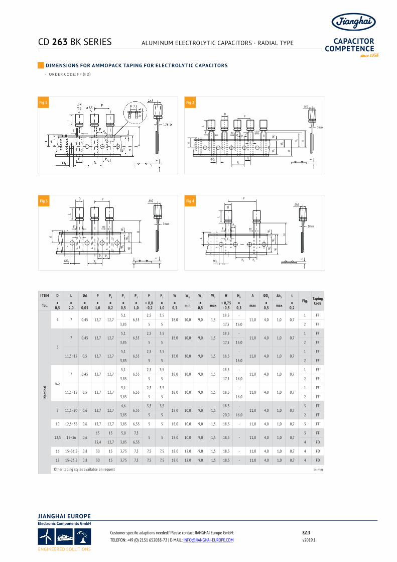
Customer specific adaptions needed? Please contact JIANGHAI Europe GmbH: / 8 13 TELEFON: +49 (0) 2151 652088-72 | E-MAIL: [email protected] v2019.1
· ORDER CODE: FF (FD)
I T E M D L Ød P P0 P1 P2 F F1 W W0 W1 W2 H H0 A ØD0 ∆h2 tFig. Taping
CodeTol. ±0,5
±2,0
±0,05
±1,0
±0,2
±0,5
±1,0
+ 0,8- 0,2
±1,0
±0,5 min ±
0,5 max + 0,75- 0,5
±0,5 max ±
0,5 max ±0,2
Nom
inal
4 7 0,45 12,7 12,75,1
6,352,5 3,5
18,0 10,0 9,0 1,518,5 -
11,0 4,0 1,0 0,71 FF
3,85 5 5 17,5 16,0 2 FF
5
7 0,45 12,7 12,75,1
6,352,5 3,5
18,0 10,0 9,0 1,518,5 -
11,0 4,0 1,0 0,71 FF
3,85 5 5 17,5 16,0 2 FF
11,5~15 0,5 12,7 12,75,1
6,352,5 3,5
18,0 10,0 9,0 1,5 18,5-
11,0 4,0 1,0 0,71 FF
3,85 5 5 16,0 2 FF
6,3
7 0,45 12,7 12,75,1
6,352,5 3,5
18,0 10,0 9,0 1,518,5 -
11,0 4,0 1,0 0,71 FF
3,85 5 5 17,5 16,0 2 FF
11,5~15 0,5 12,7 12,75,1
6,352,5 3,5
18,0 10,0 9,0 1,5 18,5-
11,0 4,0 1,0 0,71 FF
3,85 5 5 16,0 2 FF
8 11,5~20 0,6 12,7 12,74,6
6,353,5 3,5
18,0 10,0 9,0 1,518,5 -
11,0 4,0 1,0 0,73 FF
3,85 5 5 20,0 16,0 2 FF
10 12,5~36 0,6 12,7 12,7 3,85 6,35 5 5 18,0 10,0 9,0 1,5 18,5 - 11,0 4,0 1,0 0,7 3 FF
12,5 15~36 0,615 15 5,0 7,5
5 5 18,0 10,0 9,0 1,5 18,5 - 11,0 4,0 1,0 0,73 FF
25,4 12,7 3,85 6,35 4 FD
16 15~31,5 0,8 30 15 3,75 7,5 7,5 7,5 18,0 12,0 9,0 1,5 18,5 - 11,0 4,0 1,0 0,7 4 FD
18 15~25,5 0,8 30 15 3,75 7,5 7,5 7,5 18,0 12,0 9,0 1,5 18,5 - 11,0 4,0 1,0 0,7 4 FD
Other taping styles available on request in mm
D
FP1
P2
P0
W2
W1
L
W
1max
P
Фd
H 0
R
∆h2
t
A
W0
H
ФD0
120°
F1
D
F
P1 P2
P0
W2
W1
L
W
1max
P
Фd
∆h2
t
A
W0
H
ФD0
F1
D
FP1
P2P0
W2
W1
L
W
1max
P
Фd
∆h2
t
A
H
ФD0
F1
W0
DIMENSIONS FOR AMMOPACK TAPING FOR ELECTROLYTIC CAPACITORS
Fig 1 Fig 2
Fig 3 Fig 4

CD 263 BK SERIES ALUMINUM ELECTROLYTIC CAPACITORS · RADIAL TYPE
To estimate the Lifetime of a non-solid Aluminum Electrolytic
Capacitor from Jianghai, the following formulas can be utilized. The
Lifetime depends mainly on the ambient temperature, the ripple
current and, within certain limits, the operating voltage applied.
Other parameters may also affect the Lifetime. Moreover, L0 can be
interpreted in many different ways, which has a fundamental
influence on the numerical result. Jianghai offers a high transparency
by publishing the different typical definitions of Lifetimes in each
datasheet. Lifetime estimations are approximations by nature.
Please let JIANGHAI EUROPE confirm any result before using it. The
formulas given here do not constitute part of a contract nor of a
specification. The formulas do not cover additional aging effects of
certain electrolytic systems or other chemical effects. Also the
dimensions of the components may have an effect. Forced cooling or
other additional cooling-methods have a strong impact on the
Lifetime and are not covered by the formulas as defined. For the
estimation and interpretation of Lifetime, a close collaboration with
JIANGHAI EUROPE is strongly advised.
STRUCTUAL FORMULA
!
WHERE:
L Total Lifetime
L0 Lifetime under Nominal Load at Upper
Category Temperature (see catalogue)
KT Temperature Factor
KR Ripple Current Factor
KV Voltage Factor
KT TEMPERATURE FACTOR
Aluminum Electrolytic Capacitors follow roughly the 10 K rule of
Arrhenius. It is possible to estimate the Lifetime by rule of thumb:
When the operational temperature is reduced by 10 K, the Lifetime
will double. The formula for KT in detail is:
!
WHERE:
T0 Rated Temperature
TA Ambient Temperature
KR RIPPLE CURRENT FACTOR
To estimate the influence of ripple current on lifetime, Jianghai uses
a safety factor Ki. Under certain conditions this value can be set to
Ki=2, which is prolonging the lifetime. Please contact Jianghai
Europe for details and approval.
!
WITH:
!
WHERE:
IA Actual Rated Ripple Current
IR Ripple Current at Upper Category Temperature (databook value)
ΔT0 Core Temperature Rise of the capacitor
(typically 3,5 ~ 5 K for T0 = 105°C and 3,5 ~ 10K for T0= 85°C, see databook value)
Ki Basis, typically defined as
T0 = 105°C IA > IR: Ki=4
IA ≤ IR: Ki=2
T0 = 85°C Ki=2
Remark: Safety Factor Ki may be set as Ki=2 under certain defined
conditions. Please contact Jianghai Europe for approval.
>>
L = L0 ⋅ KT ⋅ KR ⋅ KV
KT = 2T0 − TA
10K
KR = KA
ΔT010K
i
A = 1 − (IAIR )
2
Customer specific adaptions needed? Please contact JIANGHAI Europe GmbH: / 9 13 TELEFON: +49 (0) 2151 652088-72 | E-MAIL: [email protected] v2019.1
LIFETIME ESTIMATION
CD 263 BK SERIES ALUMINUM ELECTROLYTIC CAPACITORS · RADIAL TYPE
KV VOLTAGE FACTOR
For Radial Electrolytic Capacitors, this part of the formula has no
impact (KV = 1). But for some bigger capacitors like Snap-In and
Screw-Terminal types with rated voltages above 160V, the operating
voltage will affect their Lifetime. It is expressed as follows:
FOR:
!
!
WHERE:
UA Actual Operating Voltage
UR Rated Voltage
FOR:
!
!
FOR:
!
!
FOR:
Radial Capacitors or UR ≤ 160V
!
FREQUENCY CORRECTION FACTORS:
If the actual Ripple Currents are not given at the same frequency like
I0, correction factors need to be applied.
!
JIANGHAI ELECTROLYTIC CAPACITOR LIFETIME ESTIMATION
FORMULA (incl. Safety Factors):
!
WITH TYPICAL VALUES:
T0 = 105°C IA > IR : Ki=4
IA ≤ IR : Ki=2
T0 = 85°C Ki=2
Δ T0= depending on the series: 3,5~10K,
see databook value
!
!
FOR:
UR ≤ 160V, Radial and
!
0,6 ≤UAUR
≤ 1
KV = (UAUR )
−2,5
0 <UAUR
< 0,6
KV = 3,59
UAUR
> 1not allowed
KV = 1
KV = 1
IA = (If 1Ff 1 )
2+ (
If 2Ff 2 )
2+ . . . (
IfnFfn )
2
L = L0 ⋅ 2T0 − TA
10K ⋅ K
1 − ( IAIR )
2⋅ΔT010K
i ⋅ (UAUR )
−n
0,6 ≤UAUR
≤ 1 → n = 2,5
0 <UAUR
< 0,6 → KV = (UAUR )
−n= 3,59
UAUR
> 1 → KV = 1
Customer specific adaptions needed? Please contact JIANGHAI Europe GmbH: / 10 13 TELEFON: +49 (0) 2151 652088-72 | E-MAIL: [email protected] v2019.1
LIFETIME ESTIMATION
}
KV

CD 263 BK SERIES ALUMINUM ELECTROLYTIC CAPACITORS · RADIAL TYPE
WARNING
JIANGHAI is not liable for any extent of possible injuries or damages to persons or things,
of any kind, caused by the improper application of and/or operating conditions harmful
to electrolytic capacitors. Misapplications which may cause failures include, but are not
limited to: ripple current or peak current or voltage above specification, operating
voltage above surge voltage specified, temperature exposure outside the specified
operating temperature range. Examples of harmful operating conditions comprise, but
are not limited to: unusual storage or transport temperatures, excessive and/or rapid
changes of ambient temperature or humidity, heavy mechanical shock or vibration,
corrosive and abrasive particles in the ambient (cooling) air, conducting dust in the
ambient (cooling) air, oil or water vapor or corrosive substances, explosive gas or dust,
operation under extremely high or low ambient pressure conditions (below or above sea
level), superimposed radio frequency voltages, radioactivity. In case of doubt about the
impact of operating conditions on capacitor performance, please contact JIANGHAI.
PERSONAL SAFETY
Electrical or mechanical misapplication of electrolytic capacitors may be hazardous.
Personal injury or property damage may result from explosion of a capacitor or from the
expulsion of electrolyte due to mechanical disruption or the release of a safety vent of a
capacitor. In case of injury or skin or eye exposure to electrolyte, immediately seek
professional medical advice. Before using electrolytic capacitors in any application,
please read these Handling Precautions, familiarizing thoroughly with the information
contained herein. Please check before using any of our electrolytic capacitors if these
components fulfill the requirements of your application and that warnings and
instructions for use are followed.
WARRANTY
The information contained in this catalogue does not form part of any quotation or
contract, is believed to be accurate, reliable and up to date. Quality data are based on the
statistical evaluations of a large quantity of parts and do not constitute a guarantee in a
legal sense. However, agreement on these specifications does mean that the customer
may claim for replacement of individual defective capacitors within the terms of delivery.
We will not assume any liability beyond the replacement of defective components. This
applies in particular to any consequential damage caused by component failure.
Furthermore it must be taken into consideration that the figures stated for lifetime,
failure rates and outlier percentages refer to the average production status and are
therefore to be understood as mean values (statistic expectations) for a large number of
delivery lots of identical capacitors. These figures are based on application experience
and data obtained from preceding tests under normal conditions, or – for purpose of
accelerated aging – more severe conditions. JIANGHAI reserves the right to change these
specifications without prior notice. Any application information given is advisory and
does not form part of any specification. The products are not primarily designed for use
in life support applications, devices or systems where malfunction of these products can
reasonably be expected to result in personal injury. JIANGHAI customers using or selling
these products for use in such applications without prior written consent of JIANGHAI do
so at their own risk and agree fully to indemnify JIANGHAI for any damage resulting from
such improper use or sale. This version of the catalogue supersedes all previous versions.
Latest versions of datasheets can be found on our homepage: www.jianghai-europe.com.
For more details on precautions and guidelines for aluminum electrolytic capacitors,
please refer to CENELEC Technical Report CLC/TR 50454:2008 E, “Guide for the
application of aluminum electrolytic capacitors”.
POLARITY
Electrolytic capacitors are polar and shall never be used with incorrect polarity, as there
is a possible danger of shorting or destruction.
RATED VOLTAGE UR
The rated voltage is marked on the capacitor and defined in the datasheets as UR. This
voltage should never be exceeded and is the maximum peak voltage including any
ripple voltages allowed to avoid a shortening of the lifetime or damage of the capacitor.
When a ripple current is applied to the capacitor, the sum of the peak ripple voltage and
bias DC voltage shall never exceed the rated voltage. It might be necessary to lower the
maximum allowed bias DC voltage, when certain ripple currents are applied to the
capacitor.
SURGE VOLTAGE
Maximum voltage, which may be applied to the capacitor for short periods of time: max.
1000 cycles of 30 sec. per 6 min., max. 5 pulses per hour. Capacitance drift +/- 15% max.
REVERSE VOLTAGE
Reverse voltages or voltages < 0V are not allowed.
RECOVERY VOLTAGE
Electric potential between the positive and negative terminal may exist as a result of
dielectric absorption. Please take action that this load does not damage other devices or
scare workers during the production process (sparks possible). If needed please discharge
the capacitor through a 1kΩ resistor.
TEMPERATURE RANGE
Use electrolytic capacitors only within the specified operating temperature range.
OVER-CURRENT
Currents exceeding the rated ripple currents should be avoided.
RIPPLE CURRENT/VOLTAGE
The combined value of DC voltage and peak AC voltage (due to ripple current) shall not
exceed the rated voltage and shall never be < 0V. Use of aluminum electrolytic capacitors
under ripple current with wide amplitudes is equivalent to rapid charge-discharge
operation.
RAPID CHARGING/DISCHARGING
Rapid charging/discharging generates severe heat and gas may be emitted which may
lead to explosion. Consult JIANGHAI about specially designed capacitors suitable for such
kind of applications. Example: Servo Drive Application
BALANCING RESISTORS
Balancing resistors should be utilized if capacitors are used in serial connection. Please
choose low-tolerance resistors to limit voltage drift.
CHARGE-DISCHARGE PROOF
JIANGHAI capacitors are charge-discharge proof, which means that 106 switching cycles
will cause capacitance reduction of less than 10%.
LIFETIME
There are many different lifetime definitions known without any true standard definition.
Take special care when capacitors are compared that the capacitors fulfill the needed
requirements. JIANGHAI publishes all conditions to be as transparent as possible. In the
case of lifetime tests with additional ripple currents, the bias DC voltage must be
reduced, so that the sum of bias DC voltage and the peak of the ripple voltage does not
exceed the Rated Voltage UR.
Load life: Period of time, during which the technical parameters of all capacitors stay
within the given limits. JIANGHAI defines this without allowing for outliers. >>
Customer specific adaptions needed? Please contact JIANGHAI Europe GmbH: / 11 13 TELEFON: +49 (0) 2151 652088-72 | E-MAIL: [email protected] v2019.1
HANDLING PRECAUTIONS
CD 263 BK SERIES ALUMINUM ELECTROLYTIC CAPACITORS · RADIAL TYPE
Useful life: Defined like load life, but with a lager range of parameter change.
Endurance test: IEC 60384-4 defines the acceptable drift criteria of electrical parameters
after the endurance tests (continuous voltage test).
Shelf Life: Definition of time with acceptable drift of capacitor parameters after storage
at upper category temperature without load. JIS-C-5102-1994
VIBRATION AND MECHANICAL STRESS
Capacitors are sensitive to vibration and mechanical forces applied on the leads. Do not
use capacitors, which have been dropped onto a rigid surface.
INSULATION
If any defect of the sleeve is visible, the component should not be used – the same holds
for any kind of visible damage. A capacitor should be electrically isolated from the
following parts: aluminum case, cathode lead wire, anode lead wire and circuit pattern,
and auxiliary terminal of snap-in type. The sleeve is not recognized as an isolator and
therefore the standard capacitor should not be used in a place where insulation function
is needed. Please contact JIANGHAI if a higher grade of insulation is required.
ENVIRONMENTAL CONDITIONS
Avoid direct contact with water, salt solution, oil, dewing conditions. Halogens generally,
especially fumigation treatment with bromides and flame retardant agents containing
halogens must be avoided. Avoid exposing to direct sunshine, ozone, ultraviolet rays and
x-ray radiation. Air Pressure: Max. 150kPa, min. 8kPa. No heavy air pressure changes are
allowed. Do not use or store in an environment containing any hazardous gas (e.g.,
hydrogen sulphide, sulphurous acid, nitrous acid, chlorine, ammonia, bromine, methyl
bromide, other halogens) or acidic or alkaline solutions.
STORAGE
Temperature 5 to 35°C, relative humidity below 75%. Electrolytic capacitors may
accumulate charge naturally during storage. In this case discharge through a 1kOhm
resistor before use (Recovery voltage). Leakage current may be increased after long
storage time. In this case the capacitor should be subjected to the rated voltage
treatment through a 1kOhm resistor before use for 1 hour, then it should be discharged
through a resistor of about 1 Ohm/Volt. Storage times above 1 year should be avoided or
rated voltage treatment may be necessary. In accordance to IEC 60384-4 electrolytic
capacitors are subject to a reforming process before acceptance testing. Rated voltage is
applied via a series resistance (100Ω: UR ≤ 100VDC, 1kΩ: UR > 100VDC).
SOLDERING
Soldering conditions (temperature, times) should be within specified conditions,
especially for SMD components. Avoid high soldering temperatures as this may reduce
lifetime or damage the capacitor. Do never dip the capacitor body into molten solder.
Flux should not be adhered to the capacitor’s body but only to its terminals. For details
and different methods please contact us.
GLUEING, CLEANING AND COATING
Do not use fixing agents or cleaning substances containing halogens. Do not use coating
and moulding components that completely seal the capacitor from the environment.
Also, never use solvents containing: halogenated hydrocarbons, alkali, petroleum,
trichloroethylene/-ethane, xylene, acetones, trichlorotrifluoroethane, tetrachloroethylene,
methylenechloride, chloroform, acetates, ketones, esters, chlorides and bromides.
MOUNTING
Other devices, which are mounted near the capacitor, should not touch the capacitor.
Additional heat coming from other components near the capacitor may reduce the
lifetime of the capacitor. Do never bend or twist the capacitor after soldering to avoid
stress on the leads. Radial capacitors are not protected against mechanical forces on the
leads. Forces on the pins might damage the capacitor. No printed circuit board tracks are
allowed between the lead pads of the capacitor. Screw Terminal capacitors should only
be mounted in an upright position.
TRANSPORT
Avoid fumigation and spraying insecticides (especially with bromides) in the import or
export procedures which can cause corrosion. This applies also to the finished devices.
MAINTENANCE
Periodical inspection should be carried out for the capacitor: visual inspection to check
pressure relief open or leakage of electrolyte, electrical characteristics as leakage current,
capacitance, and dissipation factor.
ELECTROLYTE AND SEPARATOR PAPER
Electrolyte and separator paper used in aluminum capacitors may be flammable. Also,
electrolyte is electrically conductive. Therefore, in case electrolyte gets in contact with PC
board it may cause corrosion of circuit pattern or cause short circuit between patterns,
and may lead to smoke generation or ignition in worst case.
CAUTION DURING USE OF CAPACITORS
Do not touch the terminals of capacitors. Keep the capacitor free from conductive
solution, such as acids, alkali and so on. Ensure that the operating environment of the
equipment into which the capacitor has been built is within the specified conditions
mentioned in the catalogue or specification sheets.
SAFETY VENT
The safety vent needs some free space to open properly. Allow for free headroom of at
least 2mm for diameter ≤16mm, more than 3mm for diameter 18-35mm, more than
5mm for case diameter 40mm and larger.
EMERGENCY ACTIONS
When the pressure relief vent is open and some gas blows out from the capacitor, please
turn the main switch of the equipment off or pull out the plug from the power outlet
immediately. During safety vent operation, extremely hot gas (>100°C) may blow out of
the capacitors. Do not stand close to the capacitors. In case of eye contact, rinse the open
eye(s) with clean water immediately. In case of ingestion, gargle with water immediately,
do not swallow. Do not touch electrolyte but wash skin with soap and water in case of
skin contact.
DEFINITION OF ELECTRICAL PARAMETERS
Separate documents as application notes, equivalent circuit diagrams and so on are
available on request.
PACKAGING
Please refer to the data book for details. Further information is available on request.
DISPOSAL
Scrapped capacitors are classified as scrapped metal. For disposal they are handled as
controllable industrial waste because of the nature of the contents (electrolyte). Most of
the material is aluminum and cannot be completely burned.
Jianghai Europe Electronic Components GmbH
Customer specific adaptions needed? Please contact JIANGHAI Europe GmbH: / 12 13 TELEFON: +49 (0) 2151 652088-72 | E-MAIL: [email protected] v2019.1
HANDLING PRECAUTIONS

CD 263 BK SERIES ALUMINUM ELECTROLYTIC CAPACITORS · RADIAL TYPE
JIANGHAI EUROPE ELECTRONIC COMPONENTS GMBH IS THE
EUROPEAN SALES ORGANIZATION OF NANTONG JIANGHAI
CAPACITOR CO., LTD., NANTONG (CHINA). SINCE 2004, SALES,
MARKETING, TECHNICAL SUPPORT, CUSTOMER SERVICE
TEAM AND WAREHOUSE OF JIANGHAI EUROPE ELECTRONIC
COMPONENTS GMBH ARE LOCATED IN KREFELD AND
KEMPEN (GERMANY).
» ELECTROLYTIC CAPACITORS
Jianghai has grown since its foundation in 1958 to become
the largest Chinese manufacturer of aluminum capa-citors
generating revenues of more than 450 million USD in 2018.
While Jianghai started in the beginning with the production
of specialty chemicals (e.g., electrolyte solutions), it entered
the production of aluminum electrolytic capacitors already in
1970.
» INTEGRATION OF PREMATERIAL
More recently, Jianghai extended its production range by
integrating high and low voltage anode foil etching and
forming facilities. All factories are located in mainland China:
the most important ones are in Nantong (north to Shanghai),
in Inner Mongolia, and in Xi’An area. Jianghai is well prepared
for further expansion due to its successful entrance to the
stock market in summer 2010.
» FILM CAPACITORS
Jianghai’s product range comprises aluminum electrolytic
capacitors in screw terminal, snap-in and radial leaded styles.
In 2012, the product portfolio was complemented by a range
of power film capacitors. For this new business unit, Jianghai
also follows the strategy of vertical integration and thus the
production will extend from the preparation of the plastic
film to the assembly of the finished goods. The product
portfolio of DC-Link and Snubber capacitors has been
enlarged in the year 2016 by AC-film capacitors. Highly
automated production facilities ensure the efficient mass
production of film capacitor modules. Driven by the thriving
electric vehicle market in China, Jianghai has attained a
leading position for the supply of theses customer specific
components.
» POLYMER CAPACITORS
The year 2013 was marked by a major breakthrough in R&D
for polymer aluminum electrolytic capacitors: the voltage
proof for these ultra-low ESR products was pushed out to as
much as 200V, enabling the utilization of these advanced
capacitors in more applications, e.g. in white goods, industrial
automation, telecom infrastructure, power supplies, and LED
ballasts.
» CAPACITOR COMPETENCE CENTER
Global presence of experienced sales and technical marketing
experts at offices in Europe, Asia and the Americas ensure the
local support of our customers based on sound know-how in
all project phases. In 2014 Jianghai Europe has established an
additional service for its customers in Europe: Experts for
capacitors are awaiting telephone calls or emails at the
CCCenter as a kind of hotline for all kind of technical requests.
» CUSTOMIZED PRODUCTS
Jianghai’s particular strength as a volume manufacturer is to
offer customized products. Jianghai focuses on the
demanding professional industrial segment with many power
electronics applications. Research and development in
collaboration with several specialized university institutes as
well as the access to all vital pre-materials enable Jianghai to
create engineered, customized solutions to fit smoothly into a
specific application.
Jianghai is continuously improving processes, thereby
enhancing the quality of its products and services. The list of
certificates awarded to Jianghai reflects its level of
achievement. In the year 2013, the Jianghai Europe sales
office has become certified according to ISO9001 and
ISO14001.
» CONTACT
Jianghai Europe Electronic Components GmbH
Phone +49 (21 51) 65 20 88 – 0
Fax +49 (21 51) 65 20 88 – 88
E-Mail [email protected]
URL www.jianghai-europe.com
Customer specific adaptions needed? Please contact JIANGHAI Europe GmbH: / 13 13 TELEFON: +49 (0) 2151 652088-72 | E-MAIL: [email protected] v2019.1
ABOUT US: CAPACITORS FROM JIANGHAI