Embed Size (px)
Citation preview

JCM ProductsQuick Reference Guide“WBATM Units”
Note: Some of the information in this guide may changeover time, depending on the software and possible modifica-tions with advancements in technology.
For further detailed information pertaining to procedures andtroubleshooting methods, please contact our TechnicalSupport Division of Customer Service.
Technical Support(702) 651-3444 (800) 683-7248
Parts Sales Service Department(702) 651-3445 (702) 651-3446
E-Mail: [email protected]
www.jcm-american.com

“WBATM Units”Quick Reference Troubleshooting Guide
Description Probable Cause Possible Solutions
BillRejection
Dip switches not setproperly
Roller and/or belts areexcessively dirty
Denomination disabledon game.
Credit limit not setproperly on game
Cashbox is full, or notinstalled properly
Sensors out ofcalibration, unit notcalibrated after softwareupgrade
Set Dip switches
Clean head & rollerswith mild soap andwater solution
Check game options
Set credit limit forproper acceptance
Check and verifycashbox condition
• Calibrate unit usingproper procedures
• Check for propersoftware/IDprotocol
No Activity No power to the unit/No LEDs visible
Will not startacceptance procedure/cycle
Cycles, but will notaccept bills
Validator in an errorstatus
Bad CPU board. Nolights on CPU board
Unit out of calibration
Check power source,pins, wires & connector
Check for propersoftware usage/IDprotocol
Check for proper DIPswitch and gamesettings
Run stand-alone Test toverify
Replace CPU board, orchange out unit
Calibrate unit usingproper procedures

WBATM Diagnostic TestsTestNo.
TestName Function When to Use
TransferMotor Test(Forward)
TransferMotor Test(Reverse)
PusherMechanismTest
Entire-UnitTest
SolenoidPosition Test
Sub-tests forAcceptorSensors
Sub-tests forTransportSensors
Bill ReceivingTest withoutCashbox
Bill ReceivingTest withCashbox
Transport andCashbox Test
Spins the motor in aforward direction
Spins the motor in areverse direction
Determine ifmechanisms in thecashbox are workingproperly
Repeatedly cyclesthe action of theAcceptor, Transport,and Cashbox
Activates thesolenoid todetermine if themechanisms areworking properly
Specifies any of the8 sub-tests to checksensors in theAcceptor
Specifies any of the8 sub-tests to checksensors in theTransport
To test the ability toaccept bills withoutusing the cashboxattached
To test the ability toaccept bills andstack using thecashbox*
To test the Transportand Pushermechanism of thecashbox without thehead installed
When conductingtests #8 and #9 andmotor is not heard
Same as above
When conductingtests #4 & #9 youreceive a Pushermechanism error
When the unit hasintermittent errorsthat can’t bedetected
When Stacker leverproblems aredetected duringTests #8 & #9
When trouble-shooting Acceptorproblems
When trouble-shooting Transportproblems
When troubleshoot-ing a unit that is notaccepting currencyfor verification
Troubleshooting aunit for acceptance,and test thecashbox.
When testing theTransport andPusher mechanismfor properfunctionality
1
2
3
4
5
6
7
8
9
10
*Do not perform Test #9 at the machine

1. Transfer Motor - Forward
2. Transfer Motor- Reverse
3. PusherMechanism
4. Entire UnitCycle
5. SolenoidPosition
6. Sub-test forHead Sensors*
7. Sub-test forTransport Sensors*
8. Bill Receivingw/o Cashbox
9. Bill Receivingwith Cashbox
10. Transport andCashbox
“WBATM Units”
1. Set Dip switch #8 to the “ON” position, all others to the “OFF”position. This puts the unit in Test Mode.
2. Apply power connector.
3. Select a Test Mode from the list below, and set the Dip switchesaccordingly.
4. Move Dip switch #8 to the “OFF” position. This activates thatparticular Test Mode.
(“X” in a Column = Switch ON)
How to Initiate the Standard Tests
Test# Test Name
Dip Switches1 2 3 4 5 6 7 8
X
X
X
X
X
X
X
X X X
X X X X
X X* See next page

“WBATM Units”Dip Switch Settings for Head Sensor Sub-Test
Magnetic Non-magnetic 1 2 3 4 5 6 7 8WBA-1x WBA 2x
PLEV FLEV X
Reserved PT-1/PT-3 X
PT-1 PT-2/PT-4 X
PT-2 PT-1/3 X
HPL PT-2/4 X
HPR UHPL/DHPL X
HPC UHPR/DHPR X
Reserved UHPC/DHPC X X
Dip Switch Settings for Transport Sub-Sensor Test
Troubleshooting Tests 1 2 3 4 5 6 7 8
Feed-in Sensor X
Solenoid Lever Sensor X
Feed-out Sensor X
Stacker Home Sensor X
No Cashbox Sensor X
Validator Encoder Sensor X
Stacker Encoder Sensor X
Acceptor Head Detached X X
(“X” in a Column = Switch ON)
(“X” in a Column = Switch ON)
During these tests, Dip switch No. 6 becomes the enable/disableswitch. On test 6, leave it on.
During these tests, Dip switch No. 7 becomes the enable/disableswitch. On test 7, leave it on.

Unit Error Codes:Bill Receiving Test
# ofBlinks Description Possible Cause
1
2
3
4
5
6
8
10
Cashbox full
Stacker jam
Transport error
Head-Sensor error
Acceptor headerror
Transfer motorerror
Stacker lever error
No cashbox
• Cashbox may be full• Stack motor not
spinning• Sensor not working• Stacker encoder gear
blade split
• Stacker may bejammed or blocked
• Cover open• Stacker lever problem
• Something blockingthe sensors
• Sensor problem
• Acceptor head notseated properly
• Communicationproblem
• Motor not spinning• Encoder gear split• Encoder sensor not
monitoring the themotor
• Solenoid not working• Sensor may not know
the position of theStacker level
• No cashbox installed• Cashbox sensor error• Broken optics flag
“WBATM Units”
Error 7 and 9 are not used

Bill Return Codes with and without cashbox
# ofBlinks Description Possible Cause
1
2
3
4
5
7
8
9
Crooked insertion
Magnetic pattern error
Entrance sensorsby-passed
Dark-light ratio isbelow the fixed value
Bill not detected
Photo sensor error
Photo level error
Illegal bill/note
• WBA-10, 11, 12, 13Sensor PT1 or PT2 notworking
• WBA-20, 21, 22, 23Sensor PT3 or PT4 notworking
• Bill inserted crooked
• Dirty rollers/belts• Bad mag sensor PCB
• Sensor other than PT1 &PT2 or PT3 & PT4 de-tected the presence of thebill/note while in stand-by
• Reflective sensors may notbe working
• Bill/note not detected by asensor within a specifiedperiod
• HPC, HPL, HPR or feedin sensor
• Bill/note may have a pat-tern not programmed orrecognized in memory
• The bill/note may be dirty• Overlapping bill/notes de-
tected
• The bill/note does not fallinto the range of accept-able bill/notes in program
(Cont’d)
“WBATM Units”

Bill Return Codes (con’t.)
Preventive Maintenance(Head/Transport)
• Replace belts if frayed, slick and/or worn.• It is important to keep the bill path, rollers and belts clean. The
sensor lenses are transparent and made of a polymer material.Handle them with care. To clean them, we suggest using a lint-freecloth and a mild, nonabrasive detergent, such as dish liquid soapmixed with water.
Do Not use alcohol for cleaning
Note: JCM does not recommend - cleaning cards, cleaning pads,or cleaning solutions of any kind.
Cashbox Preventive Maintenance (P/M):Do Periodic P/M on the Cashboxes to ensure proper operation. Usecompressed air via can, or air compressor to blow out paper fibers andany other debris that may build up over time. Check the belts and allmoving parts for wear and proper positioning. If this assembly doesnot operate properly, it can cause bill jams.
After completing the P/M, we recommend Calibration.
# ofBlinks Description Possible Cause
11
12
13
14
Stacker lever problems
Timing error
Bill/Note length error
Color pattern error
• Solenoid not working• Sensor may not know po-
sition of the Stacker lever
• The timing is degradedbetween the sensors thattrack the bill/note move-ment
• Bill/note is torn• Registration on bill/note
is too short
• Color pattern on the bill/note is incorrect
Important Note: After wiping, inspect lenses to ensure that nonehave been moved out of position, or are not flush with the path.

ON
1 2 3 4 5 6 7 8
WBATM - Basic Operations: US “$” DollarDip Switch Settings
WBA-10/11/12/13 ID-003
(Dir) “On” :2-way acceptance {if within firmware} “Off” :4-way acceptance {if within firmware}
(Dir) “On” :2-way acceptance {if within firmware} “Off” :4-way acceptance {if within firmware}
(I/F) “On” : ID-022 “Off” : ID-023
(Dir) “On” :2-way acceptance {if within firmware} “Off” :4-way acceptance {if within firmware}
WBA-10/11/12/13 ID-022/023 (IGT)
WBA-10/11/12/13 ID-024 (IGT)
Sw-1 Sw-2 Sw-3 Sw-4 Sw-5 Sw-6 Sw-7 Sw-8
Dir $1 $5 $10 $20 $50 $100 Off
Sw-1 Sw-2 Sw-3 Sw-4 Sw-5 Sw-6 Sw-7 Sw-8
Dir I/F $1 $5 $10 $20 $50 Off100
Sw-1 Sw-2 Sw-3 Sw-4 Sw-5 Sw-6 Sw-7 Sw-8
Dir Off $1 $5 $10 $20 $50 Off100
OFF

Auto-Calibration - SensorsDescription
• After the Acceptor’s components have been disassembledfor repair.
• After a sensor board has been replaced.• Whenever Bill/Note acceptance is degraded.• During scheduled Preventive Maintenance.• When upgrading, downloading software.
Procedures1. Remove Transport unit w/head.2. Set Dip switches 5, 6, 7, & 8 to the “ON” position, all
others to the “OFF” position.3. Connect Transport unit w/head to power source -
either host machine, or adaptive power supply.4. Listen for activation of transport motor - forward and
reverse for up to 2 seconds, then stop - READY.5. After inserting the calibration paper, black paper first, the
unit will carry the paper forward/reverse several times. When theprocess is complete, the unit willreturn the paper.
6. Wait a few moments to allow forcomplete transfer of calibration data to be stored inmemory. This is indicated via the LED on the testharness, or the bezel light on some applications with fastblinks.
7. Unsuccessful Calibrations - Check the lenses. Re-trycalibration. If necessary, refer to Error Conditions Charton the next page. Additional testing/troubleshooting maybe required.
Part #501-000032
Calibration sets a starting reference point for all opticalsensors within the unit. This can be done at the host unit orat the work bench with just a power source.
When to Calibrate
Note: When installing a new CPU, you must recalibrate.

Auto-CalibrationError Conditions Chart
Look at the indicator LED connected to the test harness, orthe bezel light. If the LED blinks from 1 to 11 times at 1/2second intervals, an error exists.
Count the number of blinks and match with the list below.If you missed the count, it will repeat after a 1-second pause.
# ofBlinks Error Found During Calibration
1
2
3
4
5
6
7
8
9
10
11
Entrance Lever Error
Solenoid Error
Entrance Sensor Error
Transport Jam
Gain Error - White or Black Level
Digital/Analog Error
Bar Code Sensor Error
Acceptor Head Error
Magnetic Setting Error
Write-in Error
Black Level Error
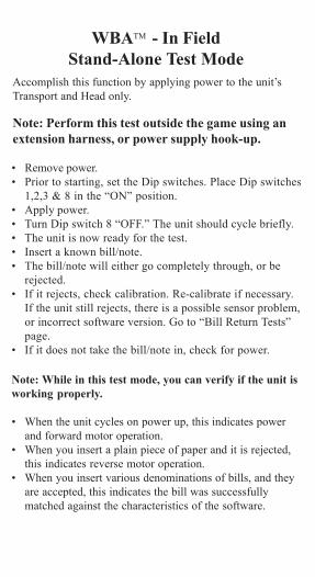
WBATM - In FieldStand-Alone Test Mode
Accomplish this function by applying power to the unit’sTransport and Head only.
Note: Perform this test outside the game using anextension harness, or power supply hook-up.
• Remove power.• Prior to starting, set the Dip switches. Place Dip switches
1,2,3 & 8 in the “ON” position.• Apply power.• Turn Dip switch 8 “OFF.” The unit should cycle briefly.• The unit is now ready for the test.• Insert a known bill/note.• The bill/note will either go completely through, or be
rejected.• If it rejects, check calibration. Re-calibrate if necessary.
If the unit still rejects, there is a possible sensor problem,or incorrect software version. Go to “Bill Return Tests”page.
• If it does not take the bill/note in, check for power.
Note: While in this test mode, you can verify if the unit isworking properly.
• When the unit cycles on power up, this indicates powerand forward motor operation.
• When you insert a plain piece of paper and it is rejected,this indicates reverse motor operation.
• When you insert various denominations of bills, and theyare accepted, this indicates the bill was successfullymatched against the characteristics of the software.

(Continued )
WBATM - DT-004 DownloadingUsing the JCM DT-004 Download Tool
DO NOT USE the 2-pin connector for power input.This is output power and can damage the DT-004.
1. Make sure power is applied to the DT-004 via a 3-pin connectorfrom the PS15-007 power supply with the adaptive harness, PartNo. 400-100067, or the power supply harness connection in thegame.
2. With the power “OFF”, be sure the 4MEG Program EPROM isinstalled properly.
3. Dip switches on WBA:Set Dip switches 6, 7, and 8 to the “ON” position, and all others tothe “Off” position.
4. Harnessing• For WBA-10/20: Use Part No. 400-10068 (Power from game to
DT-004), Part No. 400-100069 (Data from DT-004 to WBAunit).
Note: The PS15-007 can be used to substitute for a power sourceinstead of using the harness, Part No. 400-100068 at the game.When there is an RS-232 board, disconnect the board and usethe harness, Part No. 400-100042 in conjunction with harness,Part No. 400-100069
• For WBA-12/22: Use Part No. 400-100070 (Power from gameto DT-004), Part No. 400-100071 (Data from DT-004 to WBAunit).
Note: The PS15-007 can be used to substitute for a power sourceinstead of using the harness, Part No. 400-100070 at the game.When there is an RS-232 board, the WBA-12/22 can be flashedthrough the RS-232 board using the harness, Part No. 400-100071.
5. Turn the power switch on the DT-004 to the “ON” position. ThePower LED should light.
6. Verify the LEDs on the WBA CPU board are illuminated, and areblinking back and forth. This indicates download mode.

WBATM - DT-004 Downloading(con’t)
8. While downloading, the download status LEDs on the DT-004 willilluminate, indicating status of the download.
7. To begin the download process, press the “START” button. The “RDY”LED will begin to blink.
9. When the downloading is complete, the “OK” LED will light and abuzzer will sound for about a second.
10.Press the “RESET” button once, then press the “VERIFY” buttononce. After approximately 10 seconds, a buzzer will sound for abouta second, and the “OK” LED will illuminate.
11.Turn power on the DT-004 to the “OFF” position, remove theharness connectors from the unit, and return the Dip switches totheir normal operating positions.
12.To repeat the process with other units, follow these instructions from#3 through #10.
NOTE: After downloading/upgrading, recalibrate the units using thecalibration/reference paper, Part No. 501-00032 to ensure properoperation.

Examples of ID Interface Usage
This is an example of the various usages for JCM interfaces
WBA - I/FID Interface OEM (Gaming Manufacturer)
ID-044C/0C3 Aristocrat
ID-003 JCM Standard: Aristocrat, Atronics,Bally, CDS, Sigma, VLC, and WMS
ID-022/023 IGT: S-Slots, P.E., P.E. Plus
ID-024 IGT: Game King, I-Game, andVision Series
DBV - I/F
ID Interface OEM (Gaming Manufacturer)
ID-004/Bar JCM Standard: CDS and VLC
ID-011/015 Sigma and Videotronic
ID-022/023 IGT: S-Slots, P.E., P.E. Plus
ID-024 IGT: Game King, I-Game, and Vision Series
ID-044P/045P Bally
ID-044/045W WMS

JCM American Corp.Regional Offices
Western Region: Main925 Pilot Road
Las Vegas, NV 89119(800) 683-7248 Office (702) 651-0000
Fax (702) 651-0214
Mid-Western Region3000 Dundee Road, Ste. #402
Northbrook, IL 60062Office (847) 418-3354 Fax (847) 418-3357
Eastern Region3 Canale Drive, Ste. #4Egg Harbor, NJ 08234
Office (609) 677-8909 Fax (609) 677-8820
Southern Region4063 Ginger Dr., Ste. B
Biloxi, MS 39532Office (228) 354-8600 Fax (228) 354-8608
WBA Quick ReferenceManual
Part No. 960-000027 2001 JCM American, Corp.