Embed Size (px)
Citation preview

(JC1’ ~21~~$ ENGINEERING DATA TRANSMITTAL.%- ! .0 &
IEDT 625106
2. To: (Receiving Organization) 3. From: (Originating organization) 4. Retated EDT No. :
TWRS Nuclear Safety and TWRS Nuclear Safety and N/ALicensing Licensing5. Proj. /Prog./DepDivD iv.: 6. Design Authori tyl Design Agent/Cog. 7. Purchase Order No. :
N2GTDEngr. :
M. S. Tiffany N/A8.Originator Remarks: 9. Equi p.lCOmponent No. :
This Authorization Basis for the 209-E Building was approved N/Aby DOE-RL and provided reason for DOE-RL to close USQ 10. System/B ldg./Faci (ity:
TF-96-1OOO. TWRS/209-E Building11. Receiver Remarks: 11A. nesig” Base(ine Docune”t? [] Yes [X] NO 12. Major Assm. Dwg. No. :
!%tn#-sv, N/A13. Permit/Permit Application No. :
NfA14. Requi red Response Oate:
15. DATA TRANSMITTED(Al I I (c) ID)
r
I
k-m I
7%N/A
(G) (H) (1)
Reason origi- Recei.-for nator er
Tra”,- Dispo. [email protected] sition sit,..
21 1
=l=16. I I IA!v,o.,1De,km.t.,(F) Reason for Tr.ansmitk
E, S, 0, D ., NIA 1. APProval 4. Review(See WHC-CM.3-5, 2. Release 5. Post-ReviewSec.12 .71 3. Information 6. Dist. (Receipt Acknow Req”iredl I 3. Disapproved Wvmnrn.nt 6. Receipt acknowledged
17. SIGNATUREIDISTRIBUTION
,.. 4
s) I CAqmsitio”(H) & (1)
1. Approved 4. Reviewed malcomme.t2. Approved Wlcwnrnent 5. Reviewed Wcmrwrmnt
Ill6.. ApprovalDesignatorforrequiredsignatures)
{e) (H)
I
[G)(J]Name
(H)Re,- Di*p. (K) Signature [L) Date (Ml MS!N Rea. D@ (J) Name (K) %matwe IL)Date (M)MSIN

Authorization
M. S. Tiffanv
HNF-3337, Rev. O
Basis for the 209-E Building
Fluor Daniel-Hanford Inc., Richland, WA 99352U.S. Department of Energy Contract DE-AC06-96RL13200
EDT/ECN: 625106 UC: 610Org Code: 2N400 Charge Code: 101971B&R Code: EW3120072 Total Pages: 63
Key Words: 209-E Building, Authorization Basis, AB
Abstract: This Authorization Basis document is one of three documentsthat constitute the Authorization Basis for the 209-E Building. Per theU.S. Department of Energy, Richland Operations Office (RL) letter 98-WSD-074, this document, the 209-E Building Preliminary Hazards Analysis(WHC-SD-WM-TI-789), and the 209-E Building Safety Evaluation Report (97-WSD-074) constitute the Authorization Basis for the 209-E Building.This Authorization Basis and the associated controls and safety programswill remain in place until safety documentation addressing deactivationof the 209-E Building is developed by the contractor and approved by RL.
TRADEMARK DISCLAIMER. Reference herein to any specific commercial product, process, or service bytrade name, trademark, manufacturer, or otheruise, does not “ecessarf Ly constitute or imply itsendorsement, recomne”dati o”, or favoring by the united States Government or any agency the.eof orits contractors or subcontractors.
Printed in the United States of America. To obtain copies of this document, contact: DocumentCo”tro( services, P.O. Box 950, Mai(stop H6-08, Rich Land WA 99352, Phone (509) 372-2420;FBX (509) 376-4989.
~zitziitzi..,?+eLeasel Approva L Date
Approved for Public
A-640.O-072 (01/97) GEF321

HNF-3337, Rev. O
Table of ContentsAuthorization Basis for the 209-E Building
1.O PURPOSE . . . . . . . . . . . . . . . . . . . . . . . . . . . . . ..1
2,0 SCOPE . . . . . . . . . . . . . . . . . . . . . . . . . . . . . . . . 1
3.0 DEFINITIONS. . . . . 23.1 OPERABLE/OPERABILITY 23.2 IMMEDIATELY. 23.3 VERIFY 23.4 OCCUPANCY, . . . . 3
4.0 DESCRIPTION OF THE UNREVIEWED SAFETY QUESTION AND ASSOCIATED BACKGROUND3. . . . . . . . . .,., .... . . . ..”
5.0 FACILITY DESCRIPTION 45,1 Facility Condition 45.2 Facility Structure and Layout 5
5.2.1 CAR Description . . . . . . . . . . . . . . . . . . ...55.2.2 Mix Room Description . . . . . . . . . . . . . . . . . . 65.2.3 Change Room . . . . . . . . . . . . . . . . . . . . ...75.2.40 ffice Space . . . . . . . . . . . . . . . . . . ...75.2.5 Equipment Room . . . . . . . . . . . . . . . . . . ...7
5.3 Mechanical Systems . . . . . . . . . . . . . . . . . . . ...75.3.1 Exhaust Ventilation System 75.3.2 Air Purge System ..,... . . . . . . . . . . . ...85.3.3 Fire Suppression System 85.3.4 209-E Building Tanks and Tank Contamination Status 8
6.0 HAZARDS AND INITIATING EVENTS 106.1 Unfiltered Release...,.. . . . . . . ... . . . . . ...11
6.1.1 Loss of Ventilation . . . . . . . . . . . . . . . . ...116.1.2 HEPA Filter Failure . . . . . . . . . . . . . . . . ...13
6.2 Inadvertent Criticality 156.3 Inadvertent Fire System Actuation 156.4 Fire . . . . . . . . . . . . . . . . . . . . . . . . . . ...16
6.4.1 Fire in the Critical Assembly Room 166.4.2 Fire inthe Mix Room . . . . . . . . . . . . . . . . . . 18
6.5 Collapse of Drain Tank (TK-111) 186.6 Collapse of Facility . . . . . . . . . . . . . . . . . . ...196.7 Tank Release . . . . . . . . . . . . . . . . . . . . . . ...20
i

HNF-3337 Rev. O
7.0
8.0
9.0
10.0
Table of Contents209-E Building Authorization Basis (cent.)
6.8 Tank Explosion . . . . . . . . . . . . . . . . . . . . . ...206.8.1 Runaway Chemical Reactions 206,8.2 Hydrogen Generation and Subsequent Combustion 21
AUTHORIZATION BASIS DOCUMENTATION MODIFICATIONS 21
ACTIVITIES . . . . . . . . . . . . . .8.1 Authorized Activities
8.1.1 Maintenance Activities8.1.2 Surveillance8.l,30ccupancy
8.2 Activities NOT Authorized8.2,1 Ignition Sources8.2,2 Fissile Material8.2.3 Facility Deactivation
,.
,.
222222232324242424
SAFETY MANAGEMENT AND PROGRAMS APPLICABLE TO THE 209-E BUILDING: 259.1 Radiological Protection 259.2 Fire Protection Program . . . . . . . . . . . . . . . . . ...269.3 Work Control . . . . . . . . . . . . . . . . . . . . . . ...279.4 Emergency Preparedness . . . . . . . . . . . .279.5 Radioactive and Hazardous Waste Management 299.6 Testing, Surveillance, and Maintenance 299.7 Conduct of Operations . . . . . . . . . . . . . . . . . . ...299.8 Training and Procedures . . . . . . . . . . . . . . . . . ...299.9 Quality Assurance . . . . . . . . . . . . . . . . . . . . ...309.10 Configuration Management 309.11 Occurrence Reporting .,... . . . . . . . . . . . . . ...309.12 Unreviewed Safety Questions 309.13 Human Factors . . . . . . . . . . . . . . . . . . . . . . ...30
ADMINISTRATIVE CONTROL (AC) FOR HEPA FILTER NOMINAL PARTICULATE REMOVALEFFICIENCY . . . . . . . . . . . . . . . . . . . . . . . . . . ...3110.1 Requirement for HEPA Filter Control 3110.2 Program Key Elements . . . . . . . . . . . . . . . . . . ...31
ii
HNF-3337, Rev. O
11.0
12.0
13.0
14,0
Table of ContentsAuthorization Basis for the 209-E Building (cent.)
LIMITING CONDITIONS FOR OPERATION (LCOS) FOR HYOROGEN ACCUMULATION ATTHE209-E BUILDING . . . . . . . . . . . . . . . . . . . . . . ...3211.1 Air Purge System Controls...... . . . . . . . . . . ...3211.2 Exhaust Ventilation System Controls 37
SAFETY SYSTEMS, STRUCTURES, AND COMPONENTS AND SAFETY SUPPORT SYSTEMS41. . . .,,.
RESIDUAL RISK FROM CONDITIONS, OPERATIONS AND ACTIVITIES AT THE 209-EBUILDING . . . . . . . . . . . . . . . . . . . . . . . . . . . ...41
PROCESS TO IMPROVE THE TWRS AUTHORIZATION BASIS WITH RESPECT TO THE USQ42
REFERENCES .46
APPENDIXA .49
APPENDIXB .55
iii

HNF-3337, Rev. O
List of Figures
Figure 1. General Locations of Various Structures Near the 209-E Building 43
Figure 2. General Layout of the 209-E Building 44
Figure 3. 209-E Building Exhaust Ventilation System 45
iv

HNF-3337, Rev. O
AUTHORIZATIONBASISFOR THE 209-E BUILDING
M PURPOSE:
The purpose of this document is to establish an interim AuthorizationBasis for the 209-E Building for its pre-deactivation condition. Thisdocument defines the activities allowed along with controls and safetyprograms to be implemented and in part, replaces U.S. Department ofEnergy, Richland Office (RL) letter 97-WSD-160 (DOE 1997) as thefaci1ity Authorization Basis. The controls and safety programs arebased on the hazards identified in the Preliminary Hazards Analysis(FDHI 1996) in addition to supplemental information obtained throughrecent faci1ity evolutions (e.g., entries into the Critical AssemblyRoom (CAR) and Mix Room, vapor sampling of TK-111, management walkdowns). Per RL letter 98-WSD-074 (DOE 1998), this document, thePreliminary Hazards Analysis (PHA), and the 209-E 8uilding SafetyEvaluation Report (DOE 1998) constitute the Authorization Basis for the209-E Building. This Authorization 8asis and the associated controlsand safety programs WI11 remain in place unti1 safety documentationaddressing deactivation of the 209-E Building is developed by thecontractor and approved by RL.
This Authorization Basis applies only to the 209-E Building and“associated equipment. The operation of the 90-Day Resource Conservatjonand Recovery Act (RCRA) of 1976 waste storage pad, adjacent to the 209-EBuilding, is not part of this Authorization Basis but is addressedwithin the Tank Waste Remediation System (TWRS) Basis for InterimOperation (FDHI 1997a). Additional structures are in the proximity ofthe 209-E Building and are also not within the scope of thisAuthorization Basis. These structures include: 1) the Hot Semi-WorksBuilding, to the east of the 209-E Building, 2) Building 2718, operatedby Pacific Northwest National Laboratory (PNNL). 1ocated to thesouthwest of the 209-E Building, and 3) office trailer MO-434, locatedto the northeast of the 209-E Building. Figure 1 shows the 1ocations ofthe various structures with respect to the 209-E Bui1ding. Impacts tothese structures posed by the 209-E Bui1ding and impacts to the 209-EBuilding posed by these structures are addressed in Section 6.0.
1

HNF-3337, Rev. O
u DEFINITIONS:
3;1 OPERABLE/OPERABILITY
A system, subsystem, train, component, or device shal1 be OPERABLEor have OPERABILITY when it is capable of performing its specifiedsafety function(s), and (a) setpoints are within limits,(b) operating parameters necessary for OPERABILITY are within1imits, and (c) when all necessary attendant instrumentation,controls, electrical power, cooling or seal water, lubrication, orother auxi1iary equipment that are required for the system,subsystem, train, component, or device to perform its safetyfunction(s) are also capable of performing their related safetysupport function(s).
(DOE 5480.22) - annotated
3.2 IMMEDIATELY
A time of IMMEDIATELY means that the required action is to becommenced without delay, and continuously pursued in a centrol1edmanner unti1 complete. The use of IMMEDIATELY implies the highestsense of urgency. Implementation of IMMEDIATELY shal1 be giventop priority over al1 other activities.
As a TWRS faci1ity, any action at the 209-E Building requiring aresponse of IMMEDIATELY shal1 be given priority over other TWRSactivities not requiring IMMEDIATE responses.
3.3 VERIFY
A qualitative assessment to confirm or substantiate that specificplant conditions exist. This may include CO1letting sample dataor quantitative data: taking instrument readings: recording dataand information on logs, data sheets, or electronic media; andevaluating data and information according to procedures.
2

HNF-3337, Rev. O
3.4 OCCUPANCY
OCCUPANCY is the routine access of portions of the 209-E Buildingother than the CAR and Mix Room for purposes of supporting the90-day RCRA waste storage pad operations.
DESCRIPTION OF THE UNREVIEWED SAFETY OUESTION ANO ASSOCIATED BACKGROUND:
In October of 1996, an Unreviewed Safety Question (USQ)screening/determination (DESH 1996) was performed that reviewedreplacing a High Efficiency Particulate Air (HEPA) filter in the exhaustventi1ation system of the 209-E Bui1ding. The USQ process 1ed to thediscovery that the facility did not have an Authorization Basis.Subsequent review of documentation identified that the faci1ity contains562 grams of P1utoniurn(conservative total based on both PU239and PU240from a plutonium inventory performed in 1990). Additionally, aCriticality Safety Evaluation Report (WHC 1990) concluded that acriticality is not credible. Since a criticality is not credible andthe facility contains more than 450 g of plutonium, the facility isconsidered a Hazard Category 3 faci1ity per DOE-STD-1O27 (OOE 1992a).This categorization designates the 209-E Building as a nuclear facilityand therefore requires that the facility have an Authorization Basis per00E Order 5480.23 (OOE 1992b). A USQ was declared due to the existenceof a nuclear faci1ity without an Authorization Basis.
Shortly after discovering that no Authorization Basis existed for the209-E Building, the contractor’s Radiological Control organizationimposed controls as a precautionary measure for personnel safety. Sincethere were unknowns associated with the faci1ity, these controls wereintended to remain in place unti1 the hazards were addressed and theissue of not having an Authorization Basis was resolved. A PHA wasperformed to determine the hazards associated with the faci1ity. ThePHA is a qualitative analysis based on the knowledge and expertise ofindividuals familiar with the facility. It should be noted that theprecautionary controls initial1y implemented on the premise of unknowns,were carried over into an interim Authorization Basis for the 209-EBuilding. This Authorization Basis (OOE 1997) was issued August 8, 1997and was implemented at a time when there were sti11 unknowns associatedwith the facility (e.g., extent of contamination in the CAR and MixRoom, configuration and operabi1ity of SSCS as identified in 00E 1997).Information was subsequent y obtained during recent entries into the CARand Mix Room for purposes of assessing hazards and implementation of the
3

HNF-3337, Rev. O
interim controls of DOE 1997. Additional information was obtainedthrough vapor sampling activities on the drain tank (TK-111). The PHAand the subsequent y obtained physical data and observations providejustification to depart from many of the interim Authorization Basiscontrols that were originallY imposed as precautionary measures due tounknowns associated with the faci1ity.
FACILITY DESCRIPTION:
5.1 Facility Condition
The 209-E Building is located in the 200 East area of the HanfordNuclear Reservation. The faci1ity was constructed in 1960 and wasdesigned such that quantities of plutonium or uranium in solutioncould be brought into critical configurations under carefullycontrolled and monitored conditions. In the late 1980’s, PacificNorthwest Laboratory (PNL) was “directed by OOE to prepare thefaci1ity for unmanned status by Oecember 31, 1988” (PNL 1989a).The preparation for shut-down is documented to have included:1) removal of al1 bulk fissile material, 2) identification of anyprocess tanks that contain enough residual fissile material torequire flushing, 3) flushing applicable tanks with condensate toremove residual fissile material, 4) packaging and removal of thecondensate following the addition of an absorbent, 5) verifyingthe tanks were empty and venti1ated, 6) performing aNon-Obstructive Analysis (NDA) to determine quantities of anyremaining fissile material, where possible (i.e., vessel notembedded in concrete), 7) stabi1izing contamination to the extentpossible in the glove boxes and fume hoods (i.e., wiping). and8) performing modifications and maintenance on ~he fire systems(e.g., blowing dry system 1ines out, adding heaters for wet pipesystems in areas of potential freezing). These iternsweredocumented as completed in the status report (PNL 1989a). prior tofaci1ity turn-over from PNL to the Westinghouse Hanford Company in1989. The recent entries into the CAR and Mix Room along withvapor sampling of the drain tank (TK-111) have provided confidencethat these listed activities and conditions described in thestatus report are accurate.
4

HNF-3337, Rev. O
5.2 Faci1ity Structure and Layout
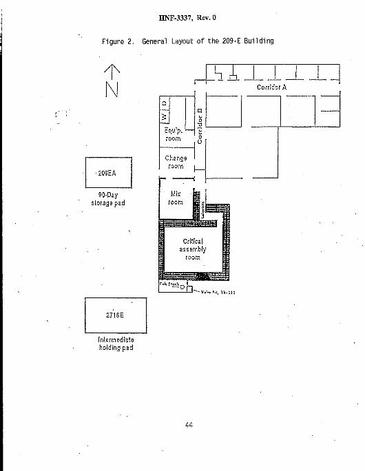
The 209-E Building (Figure 2) is an L-shaped reinforced concretestructure that includes offices, a control room, shops, anEquipment Room, a change room, the Mix Room, and the CriticalAssembly Room (CAR). The rooms that contain contaminatedequipment and material include the CAR, the Mix Room, and the “hotside” of the change room. These three rooms are the onlyRadiological Areas at the 209-E Building and were the onesprimarily addressed in the PHA.
5.2.1 CAR Description
Criticality experiments were conducted in the CAR, whichcontains two reactor hoods where the critical assemblieswere held. Each hood has its own HEPA fi1ter andinstrumentation that was monitored from the control room.Contaminated equipment 1ocated in the CAR includes four hoodassemblies and thirteen tanks, ranging from 35 L (10 gal) to400 L (106 gal). The CAR is posted in accordance with(WHC 1995a) and maintained 1ocked. Access is control1edthrough the Faci1ity Manager. Recent entries identifiedtrace amounts of alpha contamination (1ess than20 dpm/100 cmz, which is less than detectable by hand heldequipment) on the surfaces of the CAR. The radiologicaldata that was obtained can be found in the RadiologicalSurvey Report (LMHC 1997b). Three 1ocalized alphacontamination spots were identified, the highest being 46dpm/100 cm2. No beta or gamma radiation was detected.Additional alpha contamination exists within the exhaustventi1ation system, as may be reasonably expected. Thenorth, east, and west walls of the CAR are 1.5 m (5 ft)thick, while the south wall is 1 m (3 ft) thick. Both theceiling and floor are 0.6 m (2 ft) thick. A 0.8 m (2.5 ft)thick motor-operated door is 1ocated on the south side ofthe CAR. The 209-E Bui1ding structure was designed toprovide both shielding from radiation and strength towithstand pressures generated from potential uncontrol1edcriticalities (GE 1960).
Habitabi1ity was assessed by the Industrial Health andSafety organization and documented in LMHC 1997c. It was
5

HNF-3337, Rev. O
determined that there is sufficient oxygen in the CAR andMix Room for habitabi1ity. Additionally, it was determinedthat there are no toxiCO1ogical concentrateons (LMHC 1997c)that warrant either supplied air or air purifyingrespiration for personnel entry into the CAR or Mix Room.There are no toxiCO1ogical sources identified within the CARthat can change the toxicological conditions.
5.2.2 Mix Room Description
The Mix Room provided the necessary faci1ities forreceiving, handling, and preparing the various types andforms of radionuclides and chemicals used in theexperiments. This room is also venti1ated with the exhaustventi1ation system that venti1ates the CAR. Like the CAR,the Mix Room contains contaminated equipment includin9 threehood assemblies, and nine tanks, ranging from 10 L (3 gal)to 320 L (85 gal). The Mix Room is posted in accordancewith (WHC 1995a) and maintained locked. Access iscentrol1ed through the Faci1ity Manager. Recent entriesidentified minimal amounts of alpha contamination on thesurfaces of the Mix Room. The radiological data that wasobtained can be found in the Radi01ogical Survey Report(LMHC 1997b). GenerallY, the contamination was found to beless than 20 dpm/100 cmz with the exception of one localizedsmearable contamination spot that was found to be 367dpm/100 cmz.
Habitability was assessed by the Industrial Health andSafety organization and documented in LMHC 1997c. It wasdetermined that there is sufficlent oxygen in the CAR andMix Room for habitabi1ity. Additionally, it was determinedthat there are no toxiCO1ogical concentrateons (LMHC 1997c)that warrant either supplied air or air purifyingrespiration for personnel entry into the CAR or Mix Room.There are no toxiCO1ogical sources identified within the MixRoom that can change the toxiCO1ogical conditions.

HNF-3337, Rev. O
5.2.3 Change Room
The “cold” side of the Change Room is located adjacent tothe Mix Room. The “hot” side of the Change Room is locatedin the passage way between the Mlx Room and CAR. Together,both sides of the Change Room enable personnel access to theCAR and Mix Room per radi01ogical procedures (WHC 1995a).
5.2.4 Office Space
The office space of the 209-E Building includes offices.rest rooms, and a 1unch room. These 1ocations support theoperations of the 209-E 90-day storage pad and wastepackaging operations.
5.2.5 Equipment Room
The Equipment Room contains the air compressors for the airpurge and CAR fire system, chemical product storagecabinets, and the electrical breakers that supply power tothe 209-E Building.
5.3 Mechanical Systems
5.3.1 Exhaust Venti1ation System
The CAR and Mix Room are ventilated with an activeventilation system. A damper in the inlet ventilation ducthas been locked in the closed position, forcing ventilationto be supplied through infiltration only. The exhaustventi1ation system consists of fire-resistant HEPA fi1ters,an exhaust fan, and a stack. Power is supplied to the fanvia a breaker in the Equipment Room. The damper on theexhaust fan was secured in the open position to allow aventilation pathway in case of a ventilation failure. SeeFigure 3 for the general 1ayout of the exhaust venti1ationsystem.

HNF-3337, Rev. O
5.3.2 Air Purge System
Air is supplied to the twelve process tanks (see Section5.3.4) via an air purge system. The purge air exits thetanks through tubing tied into the exhaust ventilationsystem. The air purge system consists of tubing, alrcompressors, pressure reducing valves, and flow indicatingcontrol1ers (i e., rotameters). The pressure reducingvalves 1imit the supply pressure of the alr to 35 psig.The air purge flow rate to each tank is measured andadjusted by a flow indicating controller. Flow is measuredby the position of a bead as seen through a graduated glasstube with a range between 0.2 scfh and 2 scfh. Flow isadjusted by a needle valve at the base of the flowindicating controller. The flow indicating controllers areaffixed to instrumentation racks located in the CAR and MixRoom. Purge alr flow can only be verifled by entering theCAR and Mlx Room.
5.3.3 Fire Suppression System
Fire protection for the CAR is provided by a pre-actionsprinkler system, meaning the system remains dry andpressurized with air. Pressurization with air achievesfreeze protection during CO1d weather. If a fire were tooccur in the CAR, heat activated devices WOU1d actuate avalve, pressurizing the fire suppression system with water.The air compressors that supply air to the purge system,also supply air to the fire suppression system.
Unlike the CAR, the Mix Room has a wet pipe system, meaningthat it is continuously pressurized with water. The firesuppression system for the rest of the 209-E Bui1ding alsouses raw water and is continuously pressurized.
5.3.4 209-E Bui1ding Tanks and Tank Contamination Status
The fol1owing tank information was compi1ed from PNL 1987and PNL 1989a. There were twelve process tanks that wereused for solution handling. These tanks include TK-101.
8

HNF-3337, Rev. O
TK-102, TK-103, TK-104, TK-105, TK-106, located in the CARand TK-213, TK-231, TK-232, TK-233, TK-234, and TK-235,1ocated in the Mix Room. Per the status report, these tankswere f1ushed, are tied into the exhaust venti1ation system,and have an air purge system to remove any generatedhydrogen.
Another tank, TK-111, was used as a drain tank and is1ocated underground, adjacent to the south end of thefaci1ity. This passively ventilated tank was sampledroutinely, where it was determined that plutonium levelswere below 1imits for discharging the contents to a crib. Arecent vapor sample of the drain tank (TK-111) identified nodetectable flammable gas within the tank (FDHI 1997c).
One tank, TK-108, contained water and not process solution;it is open to room atmosphere, is located in the CAR, and isconsidered f1ushed since it only contained water.
The experimental vessels, TK-141, TK-161, and TK-162, have abottom drain and are vented to the exhaust venti1ationsystem for hydrogen removal. These tanks are al1 1ocated inthe CAR. As stated in the status report, TK-141 wasthoroughly flushed. The status report states that an NDAwas performed to provide “before” plutoniurnquantities(ie., baseline indications prior to decontaminationefforts), This was used as a guide to perform 1imiteddecontamination on certain experimental vessels. TK-161 andTK-162, each assayed by NOA to contain 4 g of plutonium,fell into this realm.
Tank TK-206 was used for calibration and load out ofsolutions and is located in the Mix Room. The tank wasflushed prior to facility turnover as indicated in thestatus report.
Two tanks, TK-215 and TK-216, were used as processcondensate catch tanks, are vented, and are consideredflushed since they only contained condensate. These tanksare located in the Mix Room.
Lastly, tanks TK-109 and TK-11O are designated as dump tanksand were designed to preclude criticalities at expected
9

HNF-3337, Rev. O
plutoniurnconcentrations. The dump tanks’ function was toreceive the experiment solution. ending the experiment whendesired or if the neutron flux became too high. The 35 L(10 gal) dump tanks are located in concrete two feetunderneath the CAR reactor hoods. TK-109 is known to havereceived process solutions, was flushed and is vented by theexhaust venti1ation system. There is no knowledge thatTK-11O was ever used. A tabulated tank summary is includedin Appendix A.
U HAZARDS AND INITIATING EVENTS:
This section provides the tabulated hazards and initiating events, asidentified in the PHA. The same ‘basicmethodology used for the TWRS BIOwas used for identifying needed centrols and programs. This methodologyidentifles and addresses those hazards from the PHA that: 1) “arecredible and have the potential for offsite or onsite consequences, or2) have a frequency of “Anticipated” and have potential consequences tothe faci1ity worker. An assessment is provided for each hazard,outlining any required centrols or safety programs to prevent ormltigate the consequences of the PHA identified hazards. Since therewere unknowns during preparation of the PHA, subsequent informationsupersedes information from the PHA, where overlapping. These instancesare noted in this section of this Authorization Basis document.
The possibi1ity of a runaway chemical reaction resulting in a tankexplosion hazard is addressed within Appendix B and is based on thestatus report, process knowledge, and conversations with personnelinvolved with the criticality experiments. Since runaway chemicalreaction hazards have the potential for a tank explosion resulting inpotential material release, it is addressed in the same section ashydrogen generation and subsequent combustion, The May 1997 tankexplosion at the Hanford Plutonium Reclamation Faci1ity (not associatedwith the 209-E Building), was the driver to closely assess chemicalvulnerabilities (i.e., potential for runaway chemical reactions) atother Hanford facilities. Because the incident followed the completionof the PHA, this particular type of vulnerabi1ity was not specificallYidentified or discussed in the hazards tables of the PHA.
Impacts of nearby faci1ities’ operations/hazards on the 209-E Buildinghave not been formal1y documented through a hazards analysis process.However, with the exception of the Hot Semi-Works Bui1ding, hazards
10

HNF-3337, Rev. O
imposed on the 209-E Building by the other faci1ities and areas 1istedin Section 2.0 have been addressed through the TWRS BIO EmergencyResponse Program (FOHI 1997a). Implementation of the emer9encYresponses to the hazards imposed by these faci1ities on the 209-EBuilding is through FOHI 1998b, as required by Section 9.4. Any hazardsthat may be imposed by the Hot Semi-Works Building on the 209-EBuilding, have not been addressed.
6.1 Unfi1tered Release
6.1.1 Loss of Ventilation
A loss of ventilation andof power, inadvertent fan
all of its initiators (e.g., lossshutdown, mechanical fai1ure of
fan) were assessed a frequency of “Anticipated” withpotential consequences to the facility worker. It ispostulated that 1oose contamination or hazardous materialswould migrate to the clean side of the building upon loss ofventilation. This qualitative assessment was made duringpreparation of the PHA and was based on unknown radiologicalconditions within the CAR and Mix Room. Recent entries intothe CAR and Mix Room have yielded a better understanding ofthe extent of the contamination present in the rooms.
An additional initiating event for loss of ventilation waspostulated fol1owing the development of the PHA. Thisinitisting event involves a vehicle CO11ision with theventi1ation system equipment that is 1ocated on a concretepad at the south side of the 209-E Building. Such an eventis qualitatively assessed a frequency of “Unlikely” withpotential consequences to the faci1ity worker. In the eventof a CO1lision, any damage that might occur would involvethe ducting, HEPA filter housing, or fan itself. If theducting is damaged such that a hole is created and the fanis sti11 operating, the fan would draw clean air through thehole and release it to the atmosphere after filtration. Norelease of material to the onsite receptor WOU1d occur butthe effectiveness of the venti1ation system to draw from the209-E Building would be reduced. This is the same as theloss of ventilation scenario. Similarly, a loss ofventilation would occur if the fan is impacted in theCO11ision and becomes non-oDerational Therefore, two
11

HNF-3337, Rev. O
initiators of a loss of ventilation: a hole in the ductingand failure of the fan, are assessed within this section andappropriate programs are outlined. If the HEPA filterhousing is damaged, the filter would not sit properly ~n thehousing. This is the same as an improperly installed orimproperly seated HEPA filter and is addressed in Section6.1.2.
Assessment:
The contractor Radiological Control organization hasdetermined that the extent of the surface contaminationwithin the CAR and Mix Room is minimal. Contamination isassumed to be located within the ventilation duct work andis known to exist in the reactor hoods and process tanks.Per Section 8.2, removal of permanent equipment or alteringfissile content is not allowed, minimizing the potentialrelease of additional material into the CAR and Mix Room.Therefore, barring an accidental release, the radiologicalconditions wi11 not change while the 209-E BuildingAuthorization Basis is in place, This is confirmed byradiological surveys performed within the occupied areas andat the boundaries of the radiological areas to continuallyassess the radiological conditions of the faci1ity. Thisassessment is performed in accordance with the Hanford SiteRadiological Control Manual, HSRCM-1 (WHC 1995a). Because aloss of ventilation has the potential to result inconsequences to the faci1ity worker, a program is requiredfor Radiological Control. This program is briefly describedin Section 9.1, Radlologjcal Protection, and is the same asthe existing program cited in the TWRS BIO. An additionalprogram is required to ensure appropriate responses aretaken in the event of an emerqency. This Droqram is brieflYdescribed in Section 9.4, fme~gen;y Preparedkis, and isintegral to the existing program cited in the TWRS BIO.
The vehicle collision with the ventilation equipment haspotential consequences to the faci1ity worker because itcould be postulated to result in a loss of ventilation.vehicle CO1lision with the ventilation equipment isqualitatively assessed a frequency of “Unlikely” becausearea near the ventilation equipment is not typically
A
the
accessed by motorized vehicles (e.g. automobiles, trucks,
12

HNF-3337, Rev. O
forklifts, etc.). Motorized vehicle access is minimalbecause the 209-E Buildlng parking area and surroundingroadway is not a major thoroughfare. Further, theventilation equipment is large and readily noticeable and iswel1 in view by personnel who have occasion to occupy the209-E Building area via motorized vehicle.
The contractor Industrial Health and Safety organization hasassessed the toxicological conditions of the CAR and MixRoom. It was determined that there were no toxicologicalconcentrateons that warranted either supplied alr or airpurifying respiration for personnel entry into these rooms.There are no toxiCO1ogical sources identified within the CARand Mix Room that can change the toxicological conditions.Therefore, it is concluded that toxiCO1ogical consequencesare adequately addressed by the Emergency Preparedness andWork Control programs briefly described in Sections 9.4 and9.3, respectively.
6.1.2 HEPA Filter Failure
Initiating events for an unfiltered release due to HEPAfilter failure include: 1) improper filter installation, 2)filter plugging leading to blowout, 3) fire, 4) pluggedfi1ter, and 5) mechanical damage to the filter housing by avehicle CO11ision. Improper filter installation and filterblowout have been identified within the PHA to havepotential consequences to the onsite worker and have beenassessed a frequency of “Unlikely”. Fires are addressedwithin Section 6.4 of this document, having the sameconsequences and frequency as out1ined in that section. Aplugged filter as identified in the PHA, reduces the vacuumin the faci1ity thereby creating a scenario similar to aloss of ventilation. The plugged filter hazard has the sameconsequences and frequency of a 1oss of venti1ation and istherefore addressed by Section 6.1.1 of this document. Theremaining hazard, breach of HEPA filtration, is addressedhere.
13

HNF-3337, Rev. O
Assessment:
A breach of HEPA filtration occurs during an improperinstallation, a degradation in the filter material, ormechanical damage to the filter housing. Based on theamount of material present within the duct work, reactorhoods, and process vessels, it is postulated that thishazard can result in an accident with potential onsiteconsequences. This scenario assumes that the hazard WOU1dcontain some mechanism to dislodge radiological materialsheld up in the ventilation system. These materials would bereleased to the environment through the unfi1tered path wayand are qualitatively postulated to exceed risk guidelinesfor dose to the onsite worker. Therefore, a ,controlisrequired to assess the adequacy of filter placement uponinstallation and periodically thereafter, This control isstated in Section 10.0.
The vehicle CO11ision scenario does not include a mechanismto dislodge radioactive materials held up in the processvessels or reactor hoods. The only material that ispostulated to be released WOU1d be that entrained within theHEPA filters. Information that was not considered duringpreparation of the PHA, is an assay report (PNNL 1996) thatquantified the amount of radioactive materials held withinthe previous HEPA filters. The assay results documentedmaximum radioactive material quantities within the HEPAfilters to be 0,53 g U*35and 0,032 g of Pu. Based on theassayed quantities of radioactive materials present in thefilters, any release of the radioactive materials fol1owinga vehicle collision with the filter housing is notpostulated to result in consequences exceeding onsite oroffsite risk guidelines. This is further bolstered by thefact that there are two banks of HEPA filters as shown inFigure 3. A vehicle CO11ision that would damage both banksof HEPA filters simultaneously is postulated to beincredible since the HEPA filter housings are located ondifferent sides of the concrete pad. Therefore, in theevent of a vehicle CO11ision with a HEPA filter housing, onebank of HEPA filtration would remain functional. It shouldbe noted that the PNNL assay results were based on theprevious HEPA fi1ters that had been in use for many years,The quantity of materials present on the current HEPA
14

HNF-3337, Rev. O
fiIters is therefore expected to be much 1ess than thatdocumented by the assay results. This wi11 remain trueduring the pre-deactivation period at the 209-E Buildingsince there are no activities allowed that will dislodgeadditional radioactive materials, As an added defense-in-depth measure, a visual barrier (ie. , rope) has beenerected to alert motorized vehicle operators of theventl1ation equipment,
6.2 Inadvertent Criticality
Inadvertent criticality was addressed in the PHA, where it wasassessed a frequency of “Beyond Extremely Unlikely“, Prior to thePHA, an engineering analysis assessed the status of fissilematerial in the 209-E Building and documented the results in WHC1990. Consistent with the PHA, WHC 1990 concluded that acriticality is not credible at the 209-E Building. Additionally,this facility is classified as a Limited Control Facility perSection 1.10.4 of FDHI 1997d. As a Limited Control Faci1ity, nofissile material is allowed to be added to the faci1ity.
Assessment:
Because an accident involving a criticality is not credible, thereare no additional controls required beyond those associated withthe designation of “Limited Control Faci1ity” and the excludedactivities described in Section 8,2,
6.3 Inadvertent Fire System Actuation
The PHA identified that freezing of the fire suppression system ora loss of compressed air with a failure of the fusible 1ink couldresult in a pool of water in the CAR or Mix Room. This pool ispostulated to spread contamination, resulting in potentialradi01ogical consequences to the faci1ity worker. The hazard wasassessed a frequency of “Anticipated” in the PHA.
The extent of contamination is minimal on the surfaces in the CARand Mix Room, as identified during recent entries into the CAR andMix Room. Additional1y, the status report indicated thatremaining “PU is in vessels that have been thoroughly flushed with
15

HNF-3337, Rev. O
condensate, and no further Pu removal is expected unless astronger agent is used for flushing” (PNL 1989a). Since the firesystem only uses water, the post-flushing hold up of residual Puin the tanks is not 1ikely to be mobi1ized during fire systemactuation. Because of this and because the surface contaminationin the CAR and Mix Room is minimal, inadvertent fire systemactuation would result in minimal contamination spread.
Assessment:
The spread of contamination would be minimal in case ofinadvertent actuation of the fire suppression system, However,because the consequences have been qualitatively assessed in thePHA and have not been quantitatively determined, a combination ofsafety SSC maintenance and safety programs is required. Programsinvolved include Radi01ogical Control and Emergency Response.Safety SSC maintenance is addressed in Section 8.1.1.Radiol’ogical Control and Emergency Preparedness programs arebriefly described in Sections 9.1 and 9.4, respectively.
6.4 Fire
6.4.1 Fire in the Critical Assembly Room
From the PHA, a fire occurring in the CAR, with subsequentrelease, is the accident that represents the highest risk.This was based on a loose combustible initiator. Aconsequence analysis (WHC 1996a) was prepared based on thefire hazard, where it was calculated that an unmitigatedfire in the CAR would result in dose consequences exceedingrisk guidelines to the onsite worker. Being unmitigated,this calculation did not take credit for the buildingstructure or HEPA filtration. It should be noted that theaccident exceeded risk guidelines based on the frequency of“Anticipated”. The frequency of “Anticipated” was assessedduring development of the PHA. at which time it was knownthat there were loose combustibles and potential1y flammablesolvents in the CAR and Mix Room. These iternshave beenremoved, thereby eliminating the combustible initiator ofthe fire in the CAR hazard. The electrical fire/heaterfailure initiator, noted in the PHA remains, but wasassigned a frequency of “Unlikely”. Based on the calculated
16

HNF-3337, Rev. O
consequences (WHC 1996a), a fire in the CAR with a frequencyof “Unlikely” does not exceed risk guidelines,
The Tank Farms Fire Hazards Analysis (WHC 1996b) identifiesthe possibi1ity that the CAR and Mix Room glove boxescontain Lucite panels. The analysis identifies Lucite as acombustible material and recommends that the panels eitherbe “removed or covered with a non-combustible material suchas gypsum board”. This action is not considered to benecessary during the pre-deactivation stage of the 209-EBuilding for four reasons: (1) the loose combustibles andpotential fire initiators have been removed from the CAR andMlx Room, (2) little activity will take place in the CAR andMix Rooms, (3) the few required activities which wi11 takeplace in the CAR and Mix Room do not involve potential fireinitiators, and (4) Lucite material is not a fire initiator.
Assessment:
With the removal of the 1oose combustibles and potential1yflammable solvents from the CAR, the remaining initiator offire in”the CAR is electrical fire/heater failure. Thisreduces the overal1 fire in the CAR hazard to “Unlikely”,thereby eliminating the only hazard in the PHA that could1ead to consequences exceeding risk guidelines for theonsite worker. For protection of the faci1ity worker,safety programs and maintenance of safety SSCS are availableto prevent this accident from occurring. One program, FjreProtection, is briefly described in Section 9.2 and is thesame as the existing program cited in the TWRS BIO. Theimportance of the Fire Protectfon Program at the 209-EBuilding is for faci1ity worker safety. Another applicableprogram for faci1ity worker safety is Emergency Response,and is briefly described in Section 9.4. In conclusion, theapplication of these safety programs is necessary forfaci1ity worker safety. Neither of these safety programsare required to ensure that risk guidelines are met for thefire in the CAR hazard.
17

HNF-3337, Rev. O
6.4.2 Fire in the Mix Room
The PHA assessed a fire in the Mix Room a frequency of“Unlikely” and indicated it would have potentialconsequences to the onsite worker. A consequence analysis(WHC 1996a) was performed to assess the risk of a fire inthe Mix Room. The consequence analysis determined that afire in the Mix Room would be within the “Unlikely” categoryrisk guidelines.
Assessment:
Based on the consequence analysisconsequences of a fire in the Mlxfor a fire in the CAR (33 mSv forto 41 mSv for the CAR). Based on
it can be seen that theRoom are less than thosethe Mix Room as comparedthis and because a fire in
the CAR and a fire in the Mix Room were both assessed afrequency of “Unlikely”, protection of facility worker for afire in the Mix Room is addressed by the safety programsidentified in Section 6.4.1
6.5 Collapse of Drain Tank (TK-111)
The two initiators identified within the PHA for the collapse ofthe drain tank hazard include: 1) a runaway forklift and 2) aseismic event. Of the two initiators, a seismic event was themost probable with an assessed frequency of “Unlikely”.
Assessment:
The PHA qualitatively assessed that a collapse of the drain tankresults in potentlal consequences to the onsite worker. Based onthe past use of this tank (i.e., Pu level restrictions for cribdischarge) in addition to recent measurements associated with thisdrain tank, it is concluded that the qualitatively estimatedconsequences in the PHA were overstated. The technical basis tosupport the conclusion that PHA consequences are overstated wasdocumented in FDHI 1997c. Therefore, no new centrols or safetyprograms are required to address this hazard.
18

HNF-3337, Rev. O
6.6 COT
The
apse of Facility
two initiators identified within the PHA for this hazardinclude: 1) a high wind/tornado which 1ifts the Mix Room roof and2) a seismic event which causes building CO1lapse. The highwind/tornado initiator was qualitatively assessed a frequency of“Unlikely“ with potential consequences to the faci1ity worker.Collapse of the faci1ity due to a seismic event was postulated toresult in consequences to the onsite worker and was qualitativelyassessed a frequency of “Extremely Unlikely”.
Assessment:
Based on the frequency of “Unlikely“ and potential consequences tothe faci1ity worker, applying the methodology described in Section6.0 results in no required controls or safety programs for thehigh wind/tornado initiator. However, high winds/tornados areaddressed within the Building Emergency Plan as part of theEmergency Preparedness program.
Since a CO1lapse of the faci1ity due to a seismic event waspostulated in the PHA to cause consequences to the onsite worker,safety programs are required in addition to maintenance of safetySSCS. The Hazards Summary Report (GE 1960) briefly mentionsseismic events but does not identify structural calCU1ations ordiscuss what magnitude of a seismic event that the faci1ity couldwithstand. As described in Section 5.0, the faci1ity was designedto withstand pressures generated from potential uncontrol1edcriticalities (GE 1960). GE 1960 does not quantify the pressuresgenerated from potential uncontrolled criticalities or specifydetai1s of structural design to withstand such an event. Asdescribed in Section 12.0, the structure is a safety SSC.Minimizing the risk of faci1ity CO1lapse due to a seismic eventrelies on not allowing changes to the structure which degrade thebuilding’s resiliency to a seismic event. This minimization ofrisk is integral to maintaining the structure OPERABLE, and isaddressed in Section 8.1.1. Seismic events are addressed as partof the Emergency Preparedness program brief1y described in Section9.4.
19

HNF-3337, Rev. O
6.7 Tank Release
Tank releases, as discussed in the PHA, result in a pool withpotential consequences to the faci1ity worker. This hazard wasassessed a frequency of “Anticipated”. The initiators for a tankrelease include: 1) degradation of the tank structure; 2) the tanktips over; and 3) a seismic event causes the tank to tip over.
Assessment:
Based on the frequency and potential consequences of a tankrelease, a safety program is required. An applicable program forthis hazard is the Radio70glca7 Protection program as brieflydescribed in Section 9,1, Per the program, radiological surveysof the faci1ity are performed in accordance with WHC 1995a.Another applicable program is the Emergency Preparedness program,briefly described in Section 9.4. As part of the program, spi11sare addressed within the FDHI 1998b.
6.8 Tank Explosion
A tank explosion has been identified as a hazard that presents amechanism for radioactive material to be released, resulting inconsequences to the onsite worker. Tank explosion mechanisms arediscussed in detai1 in Appendix B, with calculations providedwhere applicable. The two mechanisms that were identifiedpertaining to tank explosions are: 1) runaway chemical reactionsand 2) hydrogen generation with subsequent combustion.
6.8.1 Runaway Chemical Reactions
As discussed in Section 6.0, the potential for a runawaychemical reaction initiating a tank explosion was consideredsubsequent to the preparation of the PHA. Appendix B ofthis JCO concludes that there are no chemicalvulnerabi1ities within the tanks of the 209-E 8uilding thatcould lead to a tank explosion. This conclusion was basedon the types and quantities of chemicals used in thecriticality experiments.
20

HNF-3337 Rev. O
Assessment:
Since no chemical vulnerabi1ities exist within the tanks ofthe 209-E Building, a runaway chemical reaction resulting ina tank explosion is a hazard that does not warrant controlsor further consideration.
6.8.2 Hydrogen Generation and Subsequent Combustion
Hydrogen generation due to radiolysis of water is the othertank explosion mechanism and is one hazard identified in thePHA. The PHA assessed a frequency of “Unlikely” forhydrogen generation and subsequent combustion. BoundingcalCU1ations for hydrogen generation are provided inAppendix B.
Assessment:
Based on the frequency of “Unlikely“ and the postulatedconsequences to the onsite worker (PHA), controls arerequired to prevent hydrogen accumulation. These controlsare stated in Sections 11.1 and 11.2.
D AUTHORIZATION BASIS DOCUMENTATION MODIFICATIONS:
The safety management program and controls required to manage thehazards associated with the 209-E Building are contained in thisdocument. No changes to the TWRS 610 or Technical Safety Requirements(FDHI 1997b) are required. The citation for the approved 209-E BuildingAuthorization Basis becomes part of the Authorization Basis listmaintained in the procedure for USQS (FDHI 1997e).
21
HNF-3337, Rev. O
u! ACTIVITIES:
8.1 Authorized Activities
The following activities are authorized to be performed at the209-E Building:
8.1.1 Maintenance Activities
The authorized maintenance activities are performed inaccordance with the programs brief1y described in Section9.0 and consist of the following:
1)
2)
3)
4)
5)
6)
7)
8)
9)
Pre-filter and/or HEPA filter replacement in the mainExhaust System.
Replacement of pre-fi1ter and/or HEPA filters 1ocatedin the CAR and Mix Room.
Maintenance on the fan, motor, and duct work of theexhaust venti1ation system.
Maintenance on the air compressors in the EquipmentRoom,
Cleaning, inspection, and replacement of electricalbreakers in the Equipment Room.
Maintenance on the fire suppression system and firesuppression system water supply, including freezeprotection.
Maintenance related to building structural integrity.
Replacement of 1ighting to ensure centrols are met andpersonnel safety is maintained while in the CAR andMix Room.
Maintenance of equipment that has no impact on safetySSCS or safety SSC systems.
22

HNF-3337, Rev. O
Basis: Identifying the authorized maintenance activitiesensures that: 1) the safety SSCS relied upon bythe 209-E Building Authorization Basis to maintainan acceptable level of risk, remain OPERABLE, and2) other equipment is not excluded by the 209-EBuilding Authorization Basis from being maintainedPer Section 12.0, the safety SSCS include thebuilding structure, air purge system, and theexhaust ventilation system. Maintenance of otherequipment is authorized if it has no impact onsafety SSCS or safety SSC systems.
8.1.2 Surveillance
Routine survei1lance is authorized to be performed inaccordance with the centrols and safety programs given inSections 9.0, 10.0, and 11.0.
Basis: This activity ensures that safety assessments areperformed to minimize industrial hazards andradiological exposure.
8.1.3 Occupancy
The 209-E Building may continue to be occupied
Basis: See definition of OCCUPANCY in Section 3.4. The209-E Bui1ding occupancy supports 90-day RCRAstorage pad operations and waste packaging andhandling administrative functions. The controlsand safety programs required by the 209-E BuildingAuthorization Basis ensure that workers occupyingthe 209-E Bui1ding are afforded protection fromindustrial. radiological, and hazardous materialsafety hazards.
23

HNF-3337, Rev. O
8.2 Activities NOT Authorized
The following activities are NOT authorized:
8.2.1 Ignition Sources
Activities which could introduce an ignition source into anyopening of the tanks in the CAR and Mix Room are notauthorized.
Basis: Although any hydrogen in the tank vapor spaces isnot expected to reach flammable concentrateons,restriction of activities which could introducesparks or ignition sources in these tanks providesextra assurance that hydrogen combustion wi11 notoccur.
8.2.2 Fissile Material
Any activities altering the fissile material content orconfiguration are not authorized.
Basis: This prevents inadvertent criticalities fromoccurring due to introduction of new materialNote that smal1 amounts (less than 150 grams, asspecified in WHC 1990) of fissile material maypotentiallY be affixed to equipment (e.g., HEPAfi1ters) and therefore is al1owed to be removedduring equipment replacement. Such activities arenot considered “altering the fissi1e content orconfiguration”.
8.2.3 Facility Deactivation
Any activities removing permanent faci1ity structures of theCAR and Mix Room such as tanks, hoods, piping, etc. are notauthorized.
Basis: These activities are not authorized to occur untilsafety documentalion addressing deactivation of the209-E Building has been approved by RL. This
24

HNF-3337, Rev. O
prevents radiological conditions from changing,thus preventing the occurrence of a hazard that hasnot been considered.
SAFETY MANAGEMENT AND PROGRAMS APPLICABLE TO THE 209-E BUILOING:
Chapter 4 of the TWRS BIO describes overal1 TWRS programmaticc safetySpecific aspects of partiCU1ar importance for the 209-E Bui1ding arediscussed below.
9.1 Radiological Protection
The Radiological Protection program for the 209-E Buildingprovides for the protection of the worker during norms1operations, The worker protection program is comprised of thefol1owing elements:
. As low as reasonably achievable (ALARA) goals● Radiation worker training● Radiation exposure control. Radiological monitoring● General employee radiation training
Radiological protection activities at the Hanford Site implementthe requirements of 10 CFR 835 (CFR 1993), “Occupational RadiationProtection,” as directed by WHC 1995a. through sitewide programsidentified in the fol1owing documents:
● HSRCM-1, Hanford Site Radiological1 Contro7 Manua 1
. HNF-IP-0718, Hea7th Phys7cs Procedures
. HNF-IP-0842, TWRS Adm7nlstration
● WHC-IP-1043, WHC Occupations7 ALARA Program
. HNF-SP-1145, FDH Radiation Protection Program Implementationof Title 10 Code of Federal Regulations Part 835
The contractor Radi01ogical Control organization administers theRadiological Protection program. This organization alsoestablishes radiologica1 protection standards and procedures;
25

HNF-3337, Rev. O
provides independent review and evaluation of the program;conducts radi01ogical and dosimetry support; develops andimplements training; and coordinates the ALARA Program.
Basis: The Radiological Protection program is achieved throughexisting TWRS and Hanford sitewide procedures. Theseprocedures are in place to ensure radiation protection ofpersonnel. This program is the same as the existingsafety management program in the TWRS BIO.
9.2 Fire Protection Program
The contractor Fire Protection program is established to meet therequirements of DOE Order 5480.7A (DOE 1993), F7re Protectjon.The program uses fire detection and extinguishing systems andequipment, administrative controls, procedures, and trainedpersonnel to meet the requirements of DOE Order 5480.7A. Threeprinciples are fol1owed to prevent and mltigate the consequencesof potential fires at the 209-E Building:
. Control of ignition sources and combustible and flammablematerials
. Employee Training
● Prompt detection and suppression of fires through acombination of instal1ed fire protection systems and aprofessional fire fighting organization.
The TWRS fire protection program is implemented through theProject Hanford Fire Protection procedures.
Basis: This program is the same as the existing safetymanagement program cited in the TWRS BIO. It is in placeto minimize potential onsite exposure to radiologicalhazards as identified in the PHA resulting from a firewithin the 209-E Building.
26
HNF-3337, Rev. O
9.3 Work Control
Maintenance activities shal1 be controlled through a formal workcentrol program. The work centrol program ensures the fol1owing:
. The work scope is fully defined
. The hazards associated with the work are identified andevaluated
. Sufficient controls, based on the hazards, are identifiedand implemented to ensure that the work can be performedsafely
. The work is executed safely and the completed work isverified
Management of work activities within TWRS is defined inHNF-IP-0842, Vol V, Maintenance/Productjon Contro7 (FDHITWRS Safety is addressed in HNF-IP-0842, Vol. IX, Safety(FDHI 1997g)
Basis: This program i“sthe same as the existing safetymanagement program cited in the TWRS 810. Work
997f
management helps identify hazards on the job to ensurethat work is performed safely. Note that the UnreviewedSafety Question process is integral to the Work Centrolprogram and ensures that proposed activities are withinthe approved Authorization Basis.
9.4 Emergency Preparedness
The TWRS Emergency Preparedness program establishes planning,procedures, and training programs to effectively prepare for.manage, and respond to emergencies and incidents affecting thehealth and safety of the worker and public. As part of TWRS,emergency response at the 209-E Building has been addressed by asection of the Tank Farms Bui1ding Emergency P1an. The EmergencyPreparedness program implements the DOE 5500 series orders.
27

HNF-3337, Rev. O
The TWRS Emergency Plan currently includes descriptions of thefollowing:
●
●
✎
●
✎
●
●
✎
●
✎
✎
●
Response organizations, authorities, responsibi1ities, andrelationship with the technical support center and emergencyoperations faci1ity established for emergency response
Actions to be taken with state and local agencies forresponses to events that involve the potential for a releaseof radiological materials
Emergency classification system and associated emergencyaction levels
Notification processes and the associated communicationssystems
Methods, systems, and equipment available for assessingactual or potential emergency conditions
Protective actions required to provide maximum protection toworkers and the public
Medical resources available to assist in the event of anemergency
Technical assessment and mltigation of faci1ity emergencyconditions
Requirements for providing information to the public,offsite authorities, and local media
Emergency faci1ities and equipment available to supportemergency operations
Staffing and training needs of the Emergency ResponseOrganization
Dri11s and exercises required to develop, maintain, and testthe response capabi1ities of the Emergency ResponseOrganization
28

HNF-3337, Rev. O
TWRS Emergency Preparedness program at the 209-E Bui1ding isimplemented through the fol1owing procedures:
. HNF-IP-0263-209E, 2(79-EFac7lity Building Emergency Plan
. HNF-IP-0971, Tank Waste Remediation System (TWRS) EmergencyPreparedness Program Plan
Basis: This program is the same as the existing safetymanagement program clted in the TWRS BIO. Emergencypreparedness establishes procedures detai1ing actions tobe taken during emergency situations. The 209-E BuildingEmergency P1an includes the necessary responses to betaken for events such as spi11s, fires, and loss ofutilities (e.g., loss of ventilation).
9.5 Radioactive and Hazardous Waste Management
The 209-E,Building is a TWRS facility. Therefore, refer toSection 4.6 of FDHI 1997a for the Radioactive and Hazardous WasteManagement program.
9.6 Testing, Survei11ante, and Maintenance
The 209-E Building is a TWRS facility. Therefore, refer toSection 4.7 of FDHI 1997a for the Testing, Survei1lance, andMaintenance program.
9.7 Conduct of Operations
The 209-E Building is a TWRS facility. Therefore, refer toSection 4.B of FDHI 1997a for the Conduct of Operations program
9.8 Training and Procedures
The 209-E Building is a TWRS faci1ity. Therefore. refer toSection 4.11 of FDHI 1997a for the Training and Proceduresprogram.
29
HNF-3337, Rev. O
9.9 Quality Assurance
The 209-E Building is a TWRS faci1ity. Therefore, refer toSection 4.12 of FDHI 1997a for the Quality Assurance program
9.10 Configuration Management
The 209-E Building is a TWRS faci1ity. Therefore, refer toSection 4.15 of FDHI 1997a for the Configuration Managementprogram.
9.11 Occurrence Reporting
The 209-E Building is a TWRS faci1ity. Therefore, refer toSection 4.16 of FDHI 1997a for the Occurrence Reporting program.
9.12 Unreviewed Safety Questions
The 209-E BuiIding is a TWRS faci1ity. Therefore, refer toSection 4,17 of FDHI 1997a for the Unreviewed Safety Questionprogram.
9.13 Human Factors
The 209-E Building is a TWRS faci1ity. Therefore, refer toSection 4,18 of FDHI 1997a for the Human Factors program.
30

HNF-3337, Rev. O
m ADMINISTRATIVE CONTROL (AC) FOR HEPA FILTER NOMINAL PARTICULATE REMOVALEFFICIENCY :
10.1 Reauirement far HEPA Fi1ter Control
A program shal1 be maintained to ensure the capabi1ity of HEPAfi1ters to mitigate the potential consequences of the accidentscenarios.
10.2 PraciramKev ElementsVERIFY HEPA fi1ter nominal partiCU1ate removal efficiencyis > 99.95% by performance of an aerosol test with the design alrf1ow through the filter, according to the guidance in AmericanSociety of Mechanical Engineers (ASME) N51O, Testjng of Nuc~earAlr Treatment Systems and Energy Research and DevelopmentAdministration (ERDA) 76-21, Nuclear Air C7eanjng Handbook.
Perform the aerosol test after instal1ation and every 12 monthsthereafter.
If HEPA fi1ter efficiency does not meet the required 99.95%, shutdown the exhaust venti1ation system IMMEDIATELY and restoreefficiency prior to restoring venti1ation.
Basis:
The use of HEPA fi1ters at the required efficiency enablesfaci1ities to meet DOE criteria for normal ventilation effluentsAerosol testing is an administrative feature credited in the PHAto prevent a potential release to the environment and radiationexposure to faci1ity and on-site workers. This control isconsistent with that of Administrative Control 5.18, iternc ofFDHI 1997a for HEPA filter efficiency.
Shutting down the venti1ation system requires voluntary entry intothe Actions of LCO 11.2. Thus. the time required to restore theefficlency of theTimes required by
HEPA fi1ters is dependent on the CompletionLCO 11.2.
31

HNF-3337, Rev. O
U..lI LIMITING CONDITIONS FOR OPERATION (LCOS) FOR HYDROGEN ACCUMULATION ATTHE 209-E BUILDING:
11.1 Air Purge System Controls
LCO 11.1 The alr purge on the twelve solution handling tanks(TK-101, TK-102, TK-103 TK-104. TK-105, TK-106,TK-213, TK-231, TK-232, TK-233, TK-234, TK-235) shal1be OPERABLE.
ACTIONS
CONDITION
A. Air purgesysteminoperable.
B, Required Actionand associatedCompletion Timeof Condition Anot met.
REQUIRED ACTIONS
A.1 Restore the alrpurge system toOPERABLE status.
B.1a. Submit a Recovery
Plan to RL forinformation, and
b. Restore the airpurge system toOPERABLE status.
COMPLETIONTIME
25 days
a. IMMEDIATELY
b. 70 days
SURVEILLANCE REQUIREMENTS
SURVEILLANCE FREQUENCY
SR 11.1 VERIFY the alr purge system is 90 daysOPERABLE
32
HNF-3337, Rev. O
BACKGROUND When the 209-E Building was prepared for shut-downstatus, trace amounts of plutoniurnwere unable tobe flushed and remain in the solution handlingtanks. The status report indicates that a smal1heel of water also might remain in the tanks.Therefore, hydrogen generation is possible withinthese tanks through radiolysis of any remainingwater.
It has been postulated during RL review thatOPERABLE status of the air purge system might beaffected if there is a mechanism for the alr exitpath to be blocked, such as the presence ofcrystals formed during solution storage andhandling. Since alr purge verification historyhas not been established, it is not known if thiscondition exists within the tanks. IT, for anyreason, the exhaust air path is blocked, the tankswi11 build up pressure unti1 a pressureequi1ibriurnis reached with that of the alr purgesystem. This wi11 result in a no flow situationand wi11 eventually be identified via the flowindicating controllers during air purge flowverifications. A no flow situation would not meetthe OPERABLE requirement of this control andrestoration of flow would be required per theRequired Actions. Having no flow during the90 day period wi11 not result in any tankexceeding 25% of the LFL. This is because it hasbeen calculated that 115 days is required to reach25% of the LFL, as discussed in Appendix B.
APPLICABLE The PHA identifies hydrogen generation andSAFETY subsequent combustion as a hazard. Per the PHAANALYSIS and status report. ignition sources are 1imited
The PHA qualitatively assessed that hydrogengeneration with subsequent combustion has thepotential for consequences to the onsite worker
33

HNF-3337, Rev. O
APPLICABLE No quantitative assessment has been provided forSAFETY the hydrogen generation and subsequent combustionANALYSIS hazard,(cent.)
Bounding calculations (Appendix B) show that itwould take 115 davs to achieve 25% of the LFL forhydrogen assuming”no air purge or activeventilation. Appendix B calculations also showthat an alr purge flow rate of 0.00216 L/rein(O.00458 ft3/hr) is required for each tank toprevent hydrogen concentrateons from reaching 25%of the LFL.
LCO The requirement for the air purge system to beOPERABLE has been specified to minimlze theaccumulation of flammable gas by providing alrflow through the tank vapor space.
The air purge system is OPERABLE when there isindication of flow within the operating range ofthe individual tank flow indicating controllers.Since the flow indicating controllers have anoperating range between 0.2 scfh and 2 scfh,OPERABLE status ensures that an air purge rate ofat least 0.2 scfh is achieved. As calculated inAppendix B, 0,00458 ft3/hr is required to maintainthe vapor space below 25% of the LFL. As can beseen, an air purge rate of 0.2 scfh is sufficientto purge any hydrogen that is generated at a rateof 0.00458 ft3/hr.
ACTIONS u
In the worst case scenario, purge air flow is lostright after the 90 day survei1lance and is notdiscovered unti1 the next surveillance (i.e.. 90days later). In this case, the calculations in
34
HNF-3337, Rev. O
ACTIONS Appendix B indicate that 25 days (i.e., 115 days(cent.) minus 90 days) could elapse before 25% of the LFL
for hydrogen is reached if restoration has notoccurred. Therefore, it is seen that a hazardouscondition does not develop instantaneously, evenin the worst case loss of flow scenario.
The recovery plan describes the steps necessary torestore the system to OPERABLE status. Approvalof the recovery plan is obtained from the ProjectHanford Management Contract Oirector of Tank FarmOperations. Once approved, the recovery plan issubmitted to RL-TWRS Director, Waste StorageDivision, for information.
The 70 day completion time results from aconservative approach based on allowance toaccumulate up to 40% of the LFL during therecovery phase of the action statements. Thisassumes that the air purge system becomesinoperable immediately after the surveillance isperformed (ie. , 185 days to reach 40% of the LFLconsisting of a possible 90 day maximumsurvei1lance period and 25 days allowed actionperiod). The 40% is chosen as providing a marginof safety.
SURVEILLANCE Verification that the air purge system is OPERABLEREQUIREMENTS is performed every 90 days. More frequent
survei1lance is not prohibited. Appendix Bcalculations identify that it would take 115 daysto reach 25% of the LFL for hydrogen. Therefore,verifying that the air purge system is OPERABLE ata survei11ante frequency of 90 days ensures thatthe vapor space composition is maintained at lessthan 25% of the LFL for hydrogen.
35

HNF-3337, Rev. O
SURVEILLANCE The alr purge Flow Indicating Controllers (FICS)REQUIREMENTS at the 209-E Building are of a fixed type (i.e.,(cent.) designed and ordered from the manufacturer to be
between 0.2 and 2 standard cubic feet per hour(scTh)) and are not able to be calIbrated. Eventhough the air purge flow is a required function,not being able to calibrate the FICS does not posea problem because: 1) any verification of f1ow onscale is at least 2000 times greater than therequired f10W, 2) the calCU1ation for hydrogengeneration was based on conservative assumptions,and 3) any error in the flow measurement is on theconservative side (e.g., increased friction due tosealing within the graduated tube requires moreair flow to obtain the same reading, etc.). Falsereadings (ie. bead stuck in graduation tube)might occur in a no flow situation. Thissituation is identified during air purgeverification through needle valve adjustment andvisual identification of bead movement.
36
HNF-3337, Rev. O
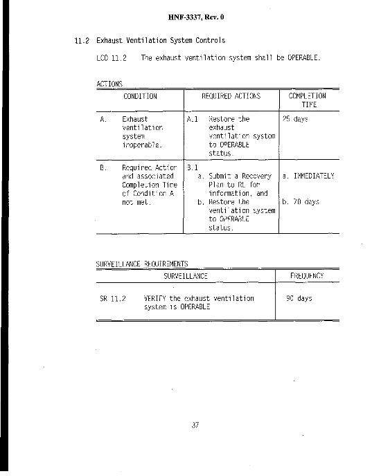
11.2 Exhaust Venti1ation System Controls
LCO 11.2 The exhaust ventilation system shal1 be OPERABLE.
ACTIONS
CONDITION REQUIREO ACTIONS
A. Exhaust A.1 Restore theventilation exhaustsystem venti1ation systeminoperable. to OPERABLE
status,
B. Required Actionand associatedCompletion Timeof Condition Anot met,
B.1a. Submit a Recovery
Plan to RL forinformation, and
b. Restore theventi1ation systemto OPERABLEstatus.
SURVEILLANCE REQUIREMENTS
COMPLETIONTIME
25 days
a. IMMEDIATELY
b, 70 days
SURVEILLANCE FREQUENCY1
SR 11.2 VERIFY the exhaust ventilation 90 dayssystem is OPERABLE
3?

HNF-3337, Rev. O
Basis:
BACKGROUND When the 209-E Building was prepared for shut-downstatus, trace amounts of PIutoniurnwere unable tobe flushed and remain in the solution handlingtanks. The status report indicates that a smal1heel of water also might remain in the tanks.Therefore, hydrogen generation is possible withinthese tanks through radiolysis of any remainingwater.
Only twelve of the twenty-two 209-E Building tanksare serviced by the air purge system. Therefore,the exhaust venti1ation system is required to beOPERABLE to remove any accumulated hydrogen fromthe remaining nine tanks within the 209-EBuilding. The only non-applicable tank is thedrain tank, TK-111, which is passively ventilatedand is located outside of the 209-E Building.
APPLICABLE The PHA identifies hydrogen generation andSAFETY subsequent combustion as a hazard. Per the PHAANALYSIS and status report, ignition sources are 1imited.
The PHA qualitatively assessed that hydrogengeneration with subsequent combustion has thepotential for consequences to the onsite worker.No quantitative assessment has been provided forthe hydrogen generation and subsequent combustionhazard.
The air purge system services those tanks whichare considered to pose the greatest risk in termsof hydrogen generation. The remaining nine tanks.which vent to the room atmosphere or to theexhaust venti1ation system, contain 1ess materialcapable of hydrogen generation. As documented inAppendix B, the air flow required to vent thesenine tanks is 0.00216 L/rein(O.00458 ft3/hr) pertank. Therefore. the safety function provided bythe ventilation system is readily met by the
38

HNF-3337, Rev. O
APPLICABLE ventilation system design (ie., nominalSAFETY 1,000 cfm).ANALYSIS(cent.)
LCO The requirement for the exhaust venti1ation systemto be OPERABLE has been specified to minimlze theaccumulation of flammable gas.
Verification that the exhaust venti1ation systemis OPERABLE consists of verifying that theventi1ation system is operating and is performedV1a: 1) visual confirmation of the exhausti ndieating 1ight located in the Equipment Roomand, 2) audible detection at the fan.
As a defense-in-depth measure, flow measurementsare taken biannuallY on the exhaust ventilationsystem. The flow measurements verify venti1ationsystem operability by ensuring flow exists withinthe exhaust venti1ation system.
ACTIONS u
In the worst case scenario, exhaust ventilation islost right after the 90 day survei1lance and isnot discovered unti1 the next survei1lance(i.e., 90 days later). In this case, thecalculations in Appendix B indicate that 25 days(i.e., 115 days minus 90 days) could elapse before25% of the LFL for hydrogen is reached ifrestoration has not occurred. Therefore, it isseen that a hazardous condition does not developinstantaneously, even in the worst case 1oss offlow scenario.
39

HNF-3337, Rev. O
ACTIONS u(cent.)
The recovery plan describes the steps necessary torestore the system to OPERABLE status. Approvalof the recovery P1an is obtained from the ProjectHanford Management Contract Director of Tank FarmOperations. Once approved, the recovery plan issubmitted to RL-TWRS Director, Waste StorageDivision, for information.
The 70 day completion time results from aconservative approach based on allowance toaccumulate up to 40% of the LFL during therecovery phase of the action statements. Thisassumes that the air purge system becomesinoperable immediately after the surveillance isperformed (i e., 185 days to reach 40% of the LFLconsisting of a possible 90 day maximumsurvei1lance period and 25 days allowed actionperiod). The 40% is chosen as providing a marginof safety.
SURVEILLANCE Verification that the exhaust venti1ation systemREQUIREMENTS is OPERABLE is performed every 90 days. More
frequent survei1lance is not prohibited.Appendix B calculations identify that it wouldtake 115 days to reach 25% of the LFL forhydrogen, Therefore, verifying the exhaustventi1ation system is OPERABLE at a survei11antefrequency of 90 days ensures that the vapor spacecomposition is maintained at less than 25% of theLFL for hydrogen.
40
HNF-3337, Rev. O
~
The fol1owing equipment is identified as safety systems, structures andcomponents:
. 209-E Building structure● Fire suppression freeze protection system. Process tank air purge system (including air compressors). Exhaust venti1ation system
Basis: The equipment is designated as safety Systems, Structures, andComponents due to the mitigative and preventive features thatthe equipment provides. The safety SSCS are al1 associatedWIth hazards that result in potential consequences to theonsite worker or “Anticlpated” consequences to the faci1ityworker. Per Section 8.1,1, these systems shal1 be maintainedto perform their intended safety functions.
~BUILDING;
Risks are minimized by the fol1owing factors: 1) combustibles and wastedrums have been removed from the CAR and Mlx Room, 2) surfacecontamination in the CAR and Mix Room is minimal, 3) safety measures forfaci1ity shut-down, as documented in the status report, have beenvalidated by observation and measurement, 4) any activity which couldmobilize residual contamination is prohibited duringpre-deactivation, 5) no new fissile material wi11 be introduced into thefaci1ity, 6) habitability for purposes of pre-deactivation activities inthe CAR and Mix Room have been confirmed by radiological and industrialhygiene surveys, 7) preventive controls have been specified for the twocredible accident scenarios (i.e., hydrogen accumulation and ignition,and breach of HEPA filtration), and 8) the 209-E Building is part ofTWRS and benefits from the safety programs required by the TWRSAuthorization Basis.
Al1 of these factors give a high degree of confidence that there are nosignificant risks to the facility worker in the 209-E Building.Further, there are no significant risks for release of radiological ortoxicological materials to the onsite worker or the public as a resultof authorized activities or postulated accidents at the 209-E Building.
41
HNF-3337, Rev. O
~ PROCESS TO IMPROVE THE TWRS AUTHORIZATION BASIS WITH RESPECT TO THE USO:
RL closed the 209-E Building USQ as stated in OOE 1998. ThisAuthorization Basis document has been approved by RL, providing anAuthorization Basis for the 209-E Building that has been derived from athorough identification and consideration of potential hazards. AnAuthorization Basis amendment for deactivation of the 209-E Buildingwi11 eventuallY replace the 209-E 8uilding Authorization Basis, onceapproved by RL.
42

HNF-3337, Rev. O
Figure 1. General Locations of VariousNear the 209-E Bui1ding
Structures
nhStreet
Fence
N;;. . . . . . . . . . . .#. z,<.,..z. . . . . . . . . . . . . . . . . . . . . . . . . . . . . . . . . .. . . . . . . . {-... - . . . . . ..- . . . . ..- . . ..”.. ”. . . . ..a. =.=.u
t
t lkJnGat~ ~,t # ‘# II
## Hazardoua#
## I Waate;t ; Axumulath‘ ‘ Low Level j,$ Pad, / Wa#epad ,## t I#t, t..- . . . . .,$#t
~ ‘ Mk3dWasta##, t Accumulation,Ipd#t,# WaateSegragatian‘f,t andSamplingTent;)#t###t#t n2718-E##.#
12thSt. I
H10th St.
; $!
S PLANT= I7th St. v
● 242-A4thst. $ *o&E n
j g<
P(J!%X
c E
i ~ ,.*cl,I 1 . . . u..
1,
:: MO-434
;/,t#},}
. . . . . . . . . . . . . . . . . . . . . . . . ,,,,-.., . . . . ,
.. . . . . . . . . . . . . . . . . . . . . . . . . . . . . . . . . ..4Form
M EAST AREA!
43
HNF-3337, Rev. O
Figure 2. General Layout of the 209-E Building
/p
N
p
o
3Equ!p.
J A I I I l_l-—— .— —CorridorA
W31 I
IChzngeroom
J
h--+- -190-Day
storagepad
13%1.v.,.fi,.n.,,,
El27t8E
Intermediateholdingpad
44

Figure 3. 209-E Building Exhaust Ventilation System ,..
“’q,000 CFM
MIX ROOM
I,
——
/
CRITICAL ASSSEMBLY ROOM/
/’.:.\.,,,..-. ——
/
,,,,,.’‘.:,. ,:
,. ‘.:.,”...., ,.,..,,.., . . ..,.. . .
AIR SUPPLY 1S BY IN-LEAKAGE.
/
—
DUALHEPAFILTERS

HNF-3337, Rev. O
REFERENCES
CFR 1993, OccupatIons1 Rad7ation Protectjon, 10 CFR 835, Code of FederalRegulations
DESH 1996, Unreviewed Safety Question: HEPA Filter Change at the 209-E
DOE
DOE
DOE
00E
DOE
00E
FOHI
FDHI
FDHI
FDHI
1
1
1
1
1
Fac7lity, TF-96-1OOO, Rev. 0, Duke Engineering and Services Hanford
~998, Contract Number DE-AC06-96RL13200 - Approva1 of Justification forCentinued Operation (JCO) for 209-E Bu?lding, 98-WSD-074, 9757083A,Department of Energy, Richland Office
1997, Contract Number DE-AC06-96RL13200 - Declaration of 209-E UnreviewedSafety Question for Deficient Authorization Basis and Institution ofInterim Controls, 97-WSD-160, 9757083A, Department of Energy, RichlandOffice
.993, F7re Protection, DOE Order 5480.7A, U. S. Department of Energy
.992a, Hazard Categorization and Accident Ana lYSis Techniques forComp1iance with DOE Order 5480.23, Nuclear Safety Analysis Reports,DOE-STD-1O27-92, U.S. Department of Energy
.992b, Nuclear Safety Ana ~ysjs, DOE Order 5480.23, U. S. Department ofEnergy
.992c, Techn7ca1 Safety Requirements, DOE Order 5480.22, U. S. Departmentof Energy
1998a, Tank Waste Remediation System (TWRS) Emergency PreparednessProgram Plan, HNF-IP-0971, Fluor Daniel Hanford Inc.
1998b, 209-E Facility L3UIldjng Emergency Plan, HNF-IP-0263-209E, FluorDaniel Hanford Inc.
1997a, Tank Waste Remediation System 8asis for Interim Operation,HNF-SD-WM-810-001, Rev O-G, Fluor Daniel Hanford Inc.
1997b, Tank Waste Remediation System Technics1 Safety Requirements,HNF-SD-WM-TSR-O06, Rev O-I, Fluor Daniel Hanford Inc.
46
FDHI
FDHI
FDHI
FDHI
FDHI
FDHI
FDHI
FDHI
HNF-3337, Rev. O
REFERENCES (cent.)
1997c, Contract Number DE-AC06-96RL13200; Information RegardingUnreviewed Safety Question ScreeninglDetermination TF-97-0869:Occurrence Report - 209-[ Solution Handling Tank Purge Air Requirements,FDH-9760653, Fluor Daniel Hanford Inc.
1997d, Criticality Safety General, Requirements, HNF-PRO-334, FluorDaniel Hanford Inc.
1997e, Unreviewed Safety Questions, HNF-IP-0842, Vol. IV, Section 5.4,Rev. 10g, Fluor Oaniel Hanford Inc.
1997f, Plajntenance/ProductionContro~, HNF-IP-0842, Vol. V, Fluor DanielHanford Inc.
1997g, Safety, HNF-IP-0842, Vol. IX, Fluor Daniel Hanford Inc.
1997h, FDH Radiation Protection Program Implementation of Title 10 Codeof Federal Regulations Part 835, HNF-SP-1145, Fluor Oaniel Hanford Inc.
1997i, Health Phys7cs Procedures, HNF-IP-0718, Fluor Daniel Hanford Inc.
1996, Pre1iminary Hazards Analysis - 209-E Building - Critical MassLaboratory, WHC-SD-MM-TI-789, Rev. O, Fluor Daniel Hanford Inc.
GE 1960, Hazards Summarv ReDort for the Hanford Plutonium Critics1 Mass
LMHC
LMHC
LMHC
PNNL
Laboratory, HW-66~66, General Electric
1997a, Calculation of Hydrogen Release Rate at Steady State for Double-Shell Tanks, HNF-SD-WM-CN-117, Rev. O, Lockheed Martin HanfordCorporation
1997b, Radi01ogical Survey Report, W309924, Lockheed Martin HanfordCorporation
1997c, Hanford Industrial Hygiene Database, Survey # 97-1252, LockheedMartin Hanford Corporation
1996, PNNL Box Assayer Results, R. J. Arthur, June 5, 1996, PacificNorthwest National Laboratoryes
47
HNF-3337, Rev. O
REFERENCES (cent.)
PNL 1989a, Status Report for Hanford’s Critica1 Mass Laboratory, [no documentnumber issued], Pacific Northwest Laboratoryes
PNL 1989b, Results of Hoid-up Measurement at 209-E, internal 1etter of H. H.VanTuyl dated January 27, 1989, Pacific Northwest Laboratoryes
PNL 1987, Safety Evalustion Document for the Critica1 Mass Laboratory Project0-370 Modlfjcations, Pacific Northwest Laboratoryes
WHC 1996a, Consequence Analysis of Two Postulated Fires in the 209-E Building,WHC-SD-WM-CN-083, Rev. O, Westinghouse Hanford Company
WHC 1996b, Tank Farms Fjre Hazards Ana 1YS7S, WHC-SD-WM-FHA-020, WestinghouseHanford Company
WHC 1995a, Hanford Site Rad7070gica7 Contro7 Manua7, HSRCM-1, Rev. 2Westinghouse Hanford Company
WHC 1995b, MHC Occupatjona7 ALARA Program, WHC-IP-1043, Westinghouse HanfordCompany
WHC 1990, CSER 90-008: Reclassification of the Critica7 Mass Laboratory,Bui7ding 209-E As a Limited Contro7 Facility, WHC-SD-SQA-CSA-20326,Rev. O, Westinghouse Hanford Company
48

APPENDIX A209-E Tank Status
This report summarizes the best avai1able information, to date, regarding the contents, and status ofthe tanks within the 209-E Building (both the CAR and the Mix Room). This information is based onmaterial contained in the Status Report for Hanford’s Crft~cd1 Mdss Laboratory (PNL 1989a).Supplemental information was obtained during a meeting (July 1997) with Mr. Harold VanTuyl, scientistand former manager of the 209-E Building at the time of turnover of the facility from PNL to WHC in1989, In the table belOW, “Verified as empty” means that the tanks were f1ushed to remove as muchplutonium as possible. Residual plutonium exists in some tanks as noted in the table below.

15 g Pu
38 g PU
123 g Pu Y
N/A
Y Critically safe slab tank used as a PuSolution Storage Tank. Verified as beingempty and purged with air to evaporateIiQuid,
Y Critically safe slab tank used as a PuSolution Storage Tank. Verifled as beingempty and purged with air to evaporateliquid.
Y Critically safe slab tank used as a PuSolution Storage Tank. Also served as adump tank for experimental vessels.Verified as being empty and purged with airto evaporate 1iquid.
Y
N/A -opentoatm.
Critically safe slab tank used as a PuSolution Storage Tank. Also served as thefeed/mix tank and dump tank forexperimental vessels. Verified as beingempty and purged with air to evaporateliquid.
Fuel Element Assembly System is open at thetop and contained water, not processsolution.
H-2-96022, Rev 2,Sht 1
H-2-96022, Rev 2,Sht 1
H-2-96019, Rev 2,Sht 1
H-2-96019, Rev 2,Sht 1
H-2-96014, Rev 2,Sht 1
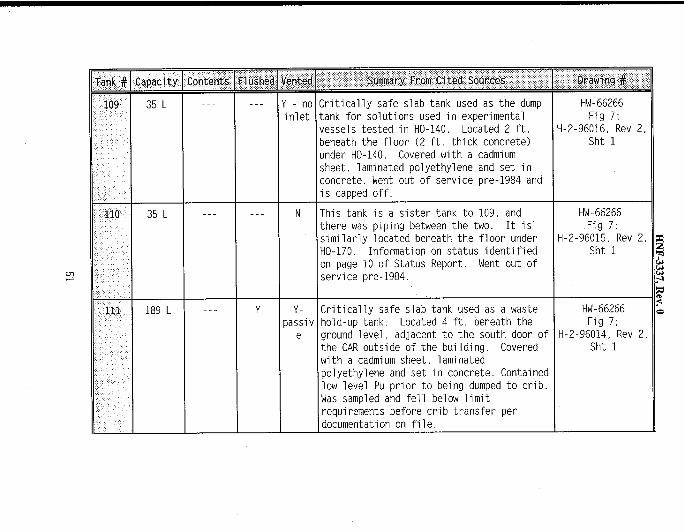
---
‘Giq-Giz--- Y-no
inlet
N
Y Y-passiv
e
litically safe slab tank used as the dump:ank for solutions used in experimental/essels tested in HO-140. Located 2 ft.)eneath the f1oor (2 ft. thick concrete),mder HO-140. Covered with a cadmiurn;heet, laminated polyethylene and set in:oncrete. Went out of service pre-1984 andis tamed off.
rhis tank is a sister tank to 109, andthere was piping between the two. It is’siml1arly 1ocated beneath the f1oor under+0-170. Information on status identifiedm page 10 of Status Report. Went out ofservice pre-1984.
:ritically safe slab tank used as a wastehold-up tank. Located 4 ft. beneath theground 1evel, adjacent to the south door ofthe CAR outside of the bui1ding. Covered~ith a cadmiurnsheet, 1aminatedpolyethylene and set in concrete. Containedlow level Pu prior to being dumped to crib.Was sampled and fell below 1imitrequirements before crib transfer perdocumentation on fi1e.
HW-66266Fig 7;
H-2-96016, Rev 2,Sht 1
HW-66266Fig 7;
H-2-96015, Rev 2,Sht 1
HW-66266Fig 7;
H-2-96014, Rev 2,Sht 1

mN
tontents
36 g Pu
4gPu
4gPu
No
No
Y-no Experimental vessel with a bottom drain,inlet Called the Bellows Tank because of its
expandable slab tank design. Tank is oneof many reactor assemblies used inconducting criticality experiments in theCAR. Test solutions were pumped into theassemblies for experiments and pumped backto the solution handling system whentesting was complete.
H-2-96016, Rev 2Sht 1
Y-no Experimental vessel with bottom drain.inlet Critical experiments were conducted in the
tank using procedure similar to thatdescribed for tank 141.
H-2-96017, Rev 2,Sht 1
Y-no Experimental vessel with boitom drain, H-2-96017,’R~v 2,inlet Critical experiments were conducted in the Sht 1
tank using procedure similar to thatdescribed for tank 141.

EilEEE
E233 320 L
234 156 L
235 156 L
47 g Pu Y Y Critically safe slab tank made of 304Lstainless steel and used as a Pu SolutionStorage Tank. Instal1ed in 86/87 as partof project D-370.
33 g Pu Y Y Critically safe slab tank made of 304Lstainless steel and used as a Pu SolutionStorage Tank. Installed in 86/87 as partof project D-370.
3gPu Y Y Critically safe slab tank made of 304Lstainless steel and used as a Pu SolutionStorage Tank. Installed in 86/87 as partof project D-370.
H-2-96024,Rev 1, Sht 2;H-2-96050,
Rev 1, Sht 1
H-2-96024,Rev 1, Sht 2;H-2-96051,Rev 1, Sht 1
H-2-96024,Rev 1, Sht 2;H-2-96051,Rev 1, Sht 1
(ncd
F1ushing: Status report (PNL 1987) addresses the tanks by system rather than individual1.Y,the~.~
individual tank status was obtained from Harold VanTuyl There is also general discussion &
of flushing status in Removal of the Crftjca17ty A7arm System From the 209-E Bui7ding.“Most plutonium is residual in permanently installed tanks in the CAR and Mix Rooms. Thetanks have been flushed and dried out, so no accountable amount of plutonium is mobile inthe tanks.”
!, !! These iternsindicate where data was not avai1able from the Status Report for Hanford’sCr7tica7 Mass Laboratory or discussion with the former faci1ity manager.

Tank # Capacity Contents P1ushed
233 320 L 47 g Pu Y
234 156 L 33 g Pu Y
m
Y Critically safe slab tank made of 304Lstainless steel and used as a Pu SolutionStorage Tank. Installed in 86/87 as partof project D-370.
Y Critically safe slab tank made of 304Lstainless steel and used as a Pu SolutionStorage Tank. Installed in 86/87 as partof project D-370.
Y Critically safe slab tank made of 304Lstainless steel and used as a Pu SolutionStorage Tank. Installed in 86/87 as partof project D-370.
H-2-96024,Rev 1, Sht 2;H-2-96050,Rev 1, Sht 1
H-2-96024,Rev 1, Sht 2;H-2-96051,Rev 1, Sht 1
H-2-96024,Rev 1, Sht 2;H-2-96051,Rev 1, Sht 1
Flushing: Status report (PNL 1987) addresses the tanks by system rather than individually, theindividual tank status was obtained from Harold VanTuyl. There is also general discussionof flushing status in Remova1 of the Critica7ity Alarm System From the 209-E Building.“Most plutonium is residual in permanently installed tanks in the CAR and Mix Rooms. Thetanks have been flushed and dried out, so no accountable amount of plutonium is mobile inthe tanks.”
,, !! These iternsindicate where data was not avai1able from the Status Report for Hanford’sCr7tlca7 Mass Laboratory or discussion with the former facility manager.

HNF-3337, Rev. O
APPENDIX B
PURPOSE:
This section of Appendix B addresses any potential chemical vulnerabi1ities atthe 209-E Building that might lead to a tank explosion.
DISCUSSION:
Critical mass experiments were mostly carried out using plutonium and uraniumsolutions. The solution handling system comprised of 12 tanks included TK-101, TK-102, TK-103, TK-104, TK-105, and TK-106 located in the CriticalAssembly Room and TK-213, TK-231, TK-232, TK-233, TK-234, and TK-235 locatedin the Mix Room. Other than nuclear poisons (e.g., boron, cadmium, andgadoliniurn),no other chemicals were added to the system for purposes ofvalante adjustments or chemical separations. Plutonium in the solutions ofplutoniurnnitrate used in the system WOU1d have existealin the +4 and +6valence states depending on the nitric acid concentrateon. NormallY, theplutonium would be in the +4 valence state but would oxidize to plutonium (+6)at acidities below 4 molar, Once the solution handling tanks were emptied ofconcentrated material during faci1ity deactivation, flushing of residual heelwith process condensate WOU1d have created conditions ideal for fermingplutoniurnpolymer [PUO~(HzO)7141.Under conditions of transient instabi1ity, asin water dilution, plutonium (+4) hydrolyzes readilY to form highly insolubleplutoniurn(+4) hydroxide. Depolymerization becomes more difficult with ageand does not readilY occur at standard conditions when the acidity isincreased. Subsequent purging of the tanks with an air sweep to evaporatemost or all of the residual liquid would cause acidity to increase which would1ikely have only a minor effect on plutoniurnpolymer formed during the tankflush. Residual soluble plutonium would concentrate as drying continued unti1solubi1ity limits are reached: approximately 2.5 moles/L for plutonium (+4).Further evaporation would result in precipitation of plutonium nitrate. Thecurrent state of the residual material in the solution handling tanks,therefore, is 1ikely a mixture of plutoniurnpolymer. plutonium nitrateprecipitate, water, nitrate ion, and P1utoniurnions. These constituents arecommon to contamination found in hoods, glove boxes, or equipment uti1ized infissile material handling operations.
Heterogeneous systems were also tested in the 209-E Critical Mass Laboratory,but did not involve use of the solution handling system. Solid forms offissi1e materials and compacts such as plutoniurnoxide-polyethylene blockswere sealed or canned for contamination control during testing. 01screte
55

HNF-3337, Rev. O
APPENDIX B (cent.)
containers holding solutions were also tested. These systems were testedusing the Remote Split-Table Assembly Machine (RSTM) installed in hood HO-170or the Fuel Element Array System (FEAS) instal1ed in TK-108. Although some ofthese fuel sources remain in the Critical Assembly Room, they do notconstitute a chemical VU1nerabi1ity because of their stable containerized orencaDsulated-solid form.
No chemical vulnerabilities are associated with the material in its currentcondition.
56

HNF-3337, Rev. O
APPENDIX B (cent.)
PURPOSE:
This section of Appendix B provides the calculation for worst case hydrogen(H*) generation rates at the 209-E Bui1ding. The hydrogen generation rateprovides a baseline for determining centrols necessary to prevent explosiveconcentrations in the tanks at the 209-E Building.
DISCUSSION:
In the Critical Assembly Room (CAR) and Mix Room at the 209-E Building, thehighest plutoniurn(Pu) residual inventory is located at TK-106 (west wal1 ofCAR), which contains 123 grams of Pu with overal1 estimated error of 35%(PNL 1989b). The analysis is based on tank TK-106 containing 170 grams ofZsgpuas a conservative approach.The analysis assumes pure water radiolysis
is the only source to generate hydrogen gas. The calCU1ated hydrogengeneration rate for the given system is 2.18E-05 L/rein,using the methodologyof LMHC 1997.
CONCLUSION:
Calculations show that it takes 115 days to reach 25% of the lowerflammability limit (LFL) for hydrogen in air from an initial steady stateconcentration (O.005% H,) when active ventilation is lost. The tank wi11reach the LFL of 4.O% H; in 470 days.
CALCULATIONS:
ParametersMass of 239PuCi per kg of 23gPuWatt per Ci of 239PuTotal Heat LoadCf from watt to eV/hourTotal eV per hourNumber of Hz per 100 eVTotal number of Hz per hour
Hydrogen Generation Rate
Hydrogen Generation Rate at 25°C
Values0.17061.30.03050.3182.25E+227.15E+210.453.22E+19
2.18E-05
UnitkgCi/kgwatt/CiwatteV/watt-houreV/hourH2/100eVHz/hour
L/min
57

HNF-3337, Rev. O
Appendix B (cent.)
Normal Operation
ParametersTank volume‘Tank Headspace (assuming 1/10 full)Hydrogen equivalent concentrateion of LFLHydrogen equivalent coticentration of 25% LFL:~ent”ilationrate per tank design specification-Steady state H2 concentration
Wi}hout Active Venti1ation System Operating
Time to”reach 25% LFL (initial is 50 ppm Hz)Time to reach LFL (initial is 50 ppm Hz)Ninimum ventilation rate keeping tank
below 25% LFLMinimum ventilation rate keeping tank
below LFL
Values400360410.450.005
115470
2.16E-03
5.23E-04
UnitLL%%L/min%
dayday
L/rein
L/rein
Note: For a tank volume of 400 L, radiolysis of 12 ml of water is sufficientto reach the LFL.
CALCULATIONS PREPAREO BY: ‘A, HU u&>/1( /~ g
CALCULATIONS REVIEWEO BY: LtiA W z~,~g
58


![2011 JC1 TimeTable (Students) 17 Feb 1022(w Venues)[1]](https://img.pdfslide.us/doc/110x75/577c7f821a28abe054a4e451/2011-jc1-timetable-students-17-feb-1022w-venues1.jpg)