Embed Size (px)
Citation preview
PPPrrreeefffeeerrrrrreeeddd IIInnnssstttrrruuummmeeennntttsss AAA DDDiiivvviiisssiiiooonnn ooofff PPPrrreeefffeeerrrrrreeeddd UUUtttiii llliii tttiiieeesss MMMaaannnuuufffaaaccctttuuurrriiinnnggg CCCooorrrpppooorrraaatttiiiooonnn
JJJCCC---222222---PPPLLL222---111000000666
DDDRRRAAAFFFTTT RRREEEGGGUUULLLAAATTTOOORRR
IIInnnssstttaaallllllaaatttiiiooonnn aaannnddd OOOpppeeerrraaatttiiiooonnn MMMAAANNNUUUAAALLL
31-35 South Street Danbury, CT 06810
Phone: 203-743-6741 Fax: 203-798-7313
Preferred Instruments Div. of Preferred Utilities Manufacturing Corp.
Phone (203) 743-6741, Fax (203) 798-7313
www.preferredinstruments.com
Installation and Operation Manual JC-22-PL2-1006 rev. 6 6-5-17 Page 2 of 12
Table of Contents
A. Description 5
B. Specifications 6
C. Installation 7
D. Wiring 8
E. Field Adjustments 10
Preferred Instruments Div. of Preferred Utilities Manufacturing Corp.
Phone (203) 743-6741, Fax (203) 798-7313
www.preferredinstruments.com
Installation and Operation Manual JC-22-PL2-1006 rev. 6 6-5-17 Page 3 of 12
WARNING! Only qualified technicians with specific knowledge of the design of the burner and all applicable burner/boiler safety codes should install, configure and commission the
JC-22-PL2-1006. Incorrect installation can result in equipment damage, injury, or death.
Note: All rights and privileges to the design of this product including the circuit layout and software are the exclusive property of Preferred Utilities Manufacturing
Corp. No part of which can be sold, used, or modified without the expressed written permission of Preferred Utilities Manufacturing Corp.

Preferred Instruments Div. of Preferred Utilities Manufacturing Corp.
Phone (203) 743-6741, Fax (203) 798-7313
www.preferredinstruments.com
Installation and Operation Manual JC-22-PL2-1006 rev. 6 6-5-17 Page 4 of 12
Preferred Instruments Div. of Preferred Utilities Manufacturing Corp.
Phone (203) 743-6741, Fax (203) 798-7313
www.preferredinstruments.com
Installation and Operation Manual JC-22-PL2-1006 rev. 6 6-5-17 Page 5 of 12
A. DESCRIPTION The JC-22-PL2-1006 is a state-of-the-art microcomputer based linear actuator that is used as a draft controller, with a solid state pressure sensor. The JC-22-PL2-1006 interfaces to any commercialized flame safeguard in the industry or any dedicated burner management system. The actuator travel range is 6” and travel time 60 seconds. The actuator has 150 lbs thrust force. The JC-22-PL2-1006 actuator provides automatic modulation for any balanced negative or positive furnace pressure application. The pressure sensing element is a linear solid state pressure transducer that is temperature compensated that generates a low drift signal. The sensor has two inlets: one for positive pressure and the other for negative pressure. The pressure is sampled via a ¼” NPT female fitting through a 1/8” flexible tube connected to one of the transducer port. There are also four miniature dials for adjusting the set point, proportional band, damping and dead band. Base on the inputs, the microcomputer activates two solid state relays, one for opening the damper and the other for closing the damper. The actuator is equipped with a relay module that includes a toggle switch for selecting between Automatic and Fully open operations. The Open Mode allows soot-blowing operation without firing interruption and also allows the burner to fire in the “Open” damper mode under emergency conditions. Open and Closed end switches shut off the power to the motor whenever the arm is fully extended or fully retracted. There is a third auxiliary switch that indicates when the damper is fully open. This auxiliary switch is used as High Fire Switch Indicator. The actuator is self-locked when power is lost. A 10-point terminal strip is used for external connections. See Wiring section. The draft controller is provided in a single compact enclosure with a removable cover and is offered as a direct replacement for Hays Cleveland model 9502-1012-B-12, facilitating field removal/installation. Preferred offers a Draft Cut Off Switch model JC22-HDPCO-8 that is a direct replacement to Hays AFS-952-55 for forced draft burners. Model JC-22-LDPCO-8 is for natural draft burners.
Preferred Instruments Div. of Preferred Utilities Manufacturing Corp.
Phone (203) 743-6741, Fax (203) 798-7313
www.preferredinstruments.com
Installation and Operation Manual JC-22-PL2-1006 rev. 6 6-5-17 Page 6 of 12
B. SPECIFICATIONS
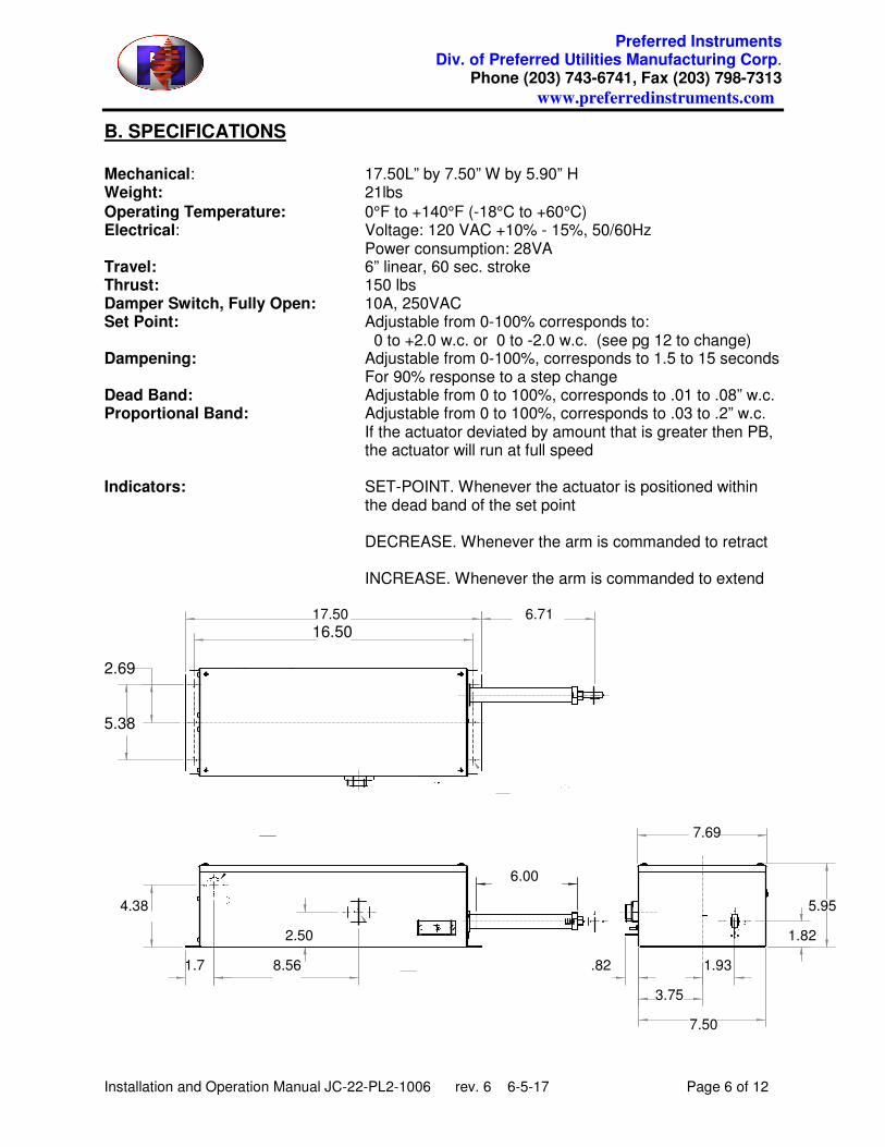
Mechanical: 17.50L” by 7.50” W by 5.90” H Weight: 21lbs
Operating Temperature: 0°F to +140°F (-18°C to +60°C) Electrical: Voltage: 120 VAC +10% - 15%, 50/60Hz Power consumption: 28VA Travel: 6” linear, 60 sec. stroke Thrust: 150 lbs Damper Switch, Fully Open: 10A, 250VAC Set Point: Adjustable from 0-100% corresponds to: 0 to +2.0 w.c. or 0 to -2.0 w.c. (see pg 12 to change) Dampening: Adjustable from 0-100%, corresponds to 1.5 to 15 seconds For 90% response to a step change Dead Band: Adjustable from 0 to 100%, corresponds to .01 to .08” w.c. Proportional Band: Adjustable from 0 to 100%, corresponds to .03 to .2” w.c. If the actuator deviated by amount that is greater then PB, the actuator will run at full speed Indicators: SET-POINT. Whenever the actuator is positioned within the dead band of the set point DECREASE. Whenever the arm is commanded to retract INCREASE. Whenever the arm is commanded to extend 17.50 6.71
16.50 2.69 5.38 7.69
6.00
4.38 5.95
2.50 1.82
1.7 8.56 .82 1.93
3.75
7.50
Preferred Instruments Div. of Preferred Utilities Manufacturing Corp.
Phone (203) 743-6741, Fax (203) 798-7313
www.preferredinstruments.com
Installation and Operation Manual JC-22-PL2-1006 rev. 6 6-5-17 Page 7 of 12
C. INSTALLATION
All system wiring must be run in accordance with the National Electrical Code and all local code requirements.
• Always remove all power to the system before wiring.
• This product is designed to work in a variety of applications and conditions; however some applications may not be applicable due to the presence of high electrical noise, lack of adequate ground connections, floating neutrals or other known or unknown conditions. It is therefore important to ensure proper system environment before installing these devices.
• All wires near hot surfaces should be rated for 90°C (195°F) or at least 25°C (50°F) higher than the surface temperature.
• The most effective ground is to run the ground wire in the same raceway as the hot and neutral from the main distribution service panel (not intermediate sub-panels) to the damper controller.
• The ground path needs to be low impedance (less than 1 ohm) to the equipment frame, which in turn needs low impedance to earth ground. For a ground path to be low impedance at RF frequencies, the connection must be made with minimum length conductors having maximum surface areas.
• All connections should be free of nonconductive coatings and protected against rust.
• Utilizing conduit as a means of providing a ground must be avoided.
Mounting: Since the draft regulator positions the outlet damper, it should be located to provide as near a straight line thrust as possible, through at least two feet of linkage, to a damper level. It is recommended to position the actuator vertically with the thrust arm extended up. The sample connection should be in the UP position if the actuator has to be mounted horizontally. Mount the actuator on a flat, solid surface with the thrust arm fully retracted when the damper is in closed position. DO NOT MOUNT THE DRAFT REGULATOR ON THE BOILER WALL OR BREECHING
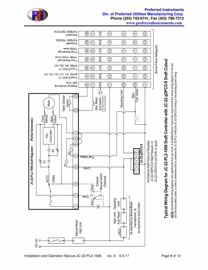
D. WIRING
Wires must be 14AWG minimum with temperature rating of at least 90C. See the following wiring diagram for external connections
Preferred Instruments Div. of Preferred Utilities Manufacturing Corp.
Phone (203) 743-6741, Fax (203) 798-7313
www.preferredinstruments.com
Installation and Operation Manual JC-22-PL2-1006 rev. 6 6-5-17 Page 8 of 12
Auto
Open External
Manual Switch
(Optional)
Manual Reset
High Limit
120 Vac
N H
Main
Fuel Valves
LWCO
High Limit
Auto Reset
Operating
Limit
As specified by Burner/Boiler
manufacturer, or
as required by local Codes
12
34
Mod. M
otor
End Switch
An External Draft Cutout is Required.
JC-22-HDPCO-8 High Pressure, or
JC-22-LDPCO-8 Low Draft, or equal
JC-22-xD
PCO-8
Operating Limit
switch
type
Burner Flame Safeguard
Typical Wiring Diagram for JC
-22-PL2-1006 Draft Controller with JC-22-xD
PCO-8 Draft Cutout
NOTE:Burner/Boiler wiring diagram
s vary significantly from
job to job. A Qualified Burner Technician must consult the actual wiring diagram
for the job,
and the local safety codes, in order to determine how to interface the JC-22-PL2-1006 and JC-22-xDPCO-8 wiring to the existing burner wiring.
Motor
Close
Retract
Open
Extend
PID
Controller
K1
K2K2
K1
AUTO
OPEN
Open Dam
per
Switch
BD
EA
12
11
42
31
JC-22-PL2-1006 Draft Regulator (Partial Schem
atic)
(HFS=High Fire Switch)
(LFS= Low Fire Switch)
18 1 25
23 2
HFS
D8 L1
13 7 L2
HFS
DM L1
13 7 L2
LFS
8M L1 3 7 L2
HFS
DM L1 3 7 L2
LFS
519 4 6 9 L2
HFS
518 4 6 9 L2
LFS
Preferred Instruments Div. of Preferred Utilities Manufacturing Corp.
Phone (203) 743-6741, Fax (203) 798-7313
www.preferredinstruments.com
Installation and Operation Manual JC-22-PL2-1006 rev. 6 6-5-17 Page 9 of 12
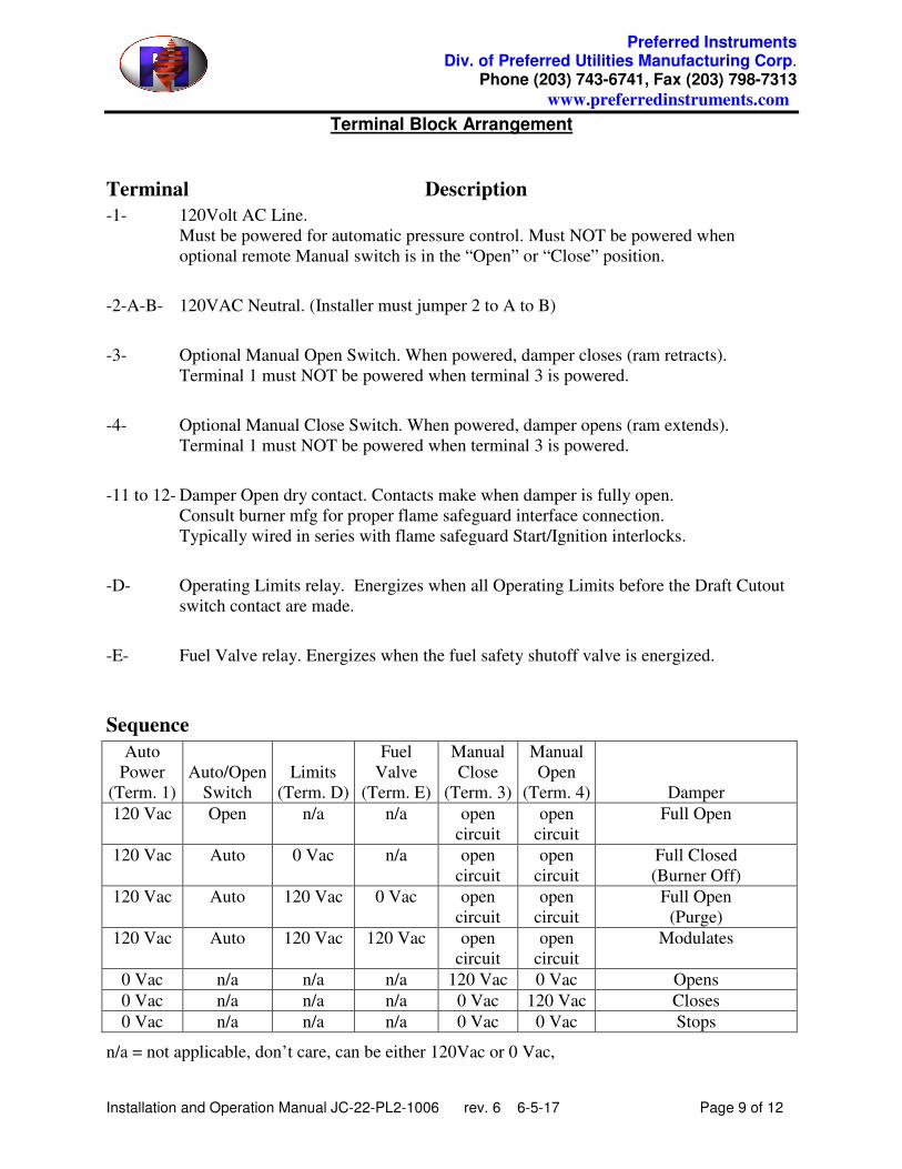
Terminal Block Arrangement
Terminal Description
-1- 120Volt AC Line.
Must be powered for automatic pressure control. Must NOT be powered when
optional remote Manual switch is in the “Open” or “Close” position.
-2-A-B- 120VAC Neutral. (Installer must jumper 2 to A to B)
-3- Optional Manual Open Switch. When powered, damper closes (ram retracts).
Terminal 1 must NOT be powered when terminal 3 is powered.
-4- Optional Manual Close Switch. When powered, damper opens (ram extends).
Terminal 1 must NOT be powered when terminal 3 is powered.
-11 to 12- Damper Open dry contact. Contacts make when damper is fully open.
Consult burner mfg for proper flame safeguard interface connection.
Typically wired in series with flame safeguard Start/Ignition interlocks.
-D- Operating Limits relay. Energizes when all Operating Limits before the Draft Cutout
switch contact are made.
-E- Fuel Valve relay. Energizes when the fuel safety shutoff valve is energized.
Sequence
Auto
Power
(Term. 1)
Auto/Open
Switch
Limits
(Term. D)
Fuel
Valve
(Term. E)
Manual
Close
(Term. 3)
Manual
Open
(Term. 4)
Damper
120 Vac Open n/a n/a open
circuit
open
circuit
Full Open
120 Vac Auto 0 Vac n/a open
circuit
open
circuit
Full Closed
(Burner Off)
120 Vac Auto 120 Vac 0 Vac open
circuit
open
circuit
Full Open
(Purge)
120 Vac Auto 120 Vac 120 Vac open
circuit
open
circuit
Modulates
0 Vac n/a n/a n/a 120 Vac 0 Vac Opens
0 Vac n/a n/a n/a 0 Vac 120 Vac Closes
0 Vac n/a n/a n/a 0 Vac 0 Vac Stops
n/a = not applicable, don’t care, can be either 120Vac or 0 Vac,
Preferred Instruments Div. of Preferred Utilities Manufacturing Corp.
Phone (203) 743-6741, Fax (203) 798-7313
www.preferredinstruments.com
Installation and Operation Manual JC-22-PL2-1006 rev. 6 6-5-17 Page 10 of 12
E. FIELD ADJUSTMENTS
Place the control into “AUTO” Mode after wiring to code and installing the piping and linkage. Turn power on only after the burner manufacture instructions are understood and executed.
After main flame has been established in modulation mode, set the following adjustments:
1. Setpoint: Turn set point adjustment to the optimum position. The factory set range (0” to -2” or 0” to +2”) is indicated on the label near the adjustment pots. The range can be changed by following the directions on page 12.
2. Damping: Turn clockwise to reduce actuator hunting caused by flame induced pressure pulsations.
3. Dead-Band: Establishes a zone above and below the set point, within which the actuator does not move. Turn the dial clockwise to increase the dead band. Turn the dial counterclockwise to decrease the dead band. Adjustment range is +-.01to .08” w.c.
4. Proportional Band: Adjusts the amount of pressure deviation from set-point required to cause the actuator to move at full speed. Pressure deviations smaller than the proportional band cause the actuator to move more slowly, in proportion to the deviation from setpoint.
Preferred Instruments Div. of Preferred Utilities Manufacturing Corp.
Phone (203) 743-6741, Fax (203) 798-7313
www.preferredinstruments.com
Installation and Operation Manual JC-22-PL2-1006 rev. 6 6-5-17 Page 11 of 12
LED Indicators
INCREASE (yellow) The ram tube is extending, which opens the damper.
DECREASE (yellow) The ram tube is retracting, which closes the damper.
SETPOINT (green). The pressure is near the setpoint (within +/- the deadband)
Preferred Instruments Div. of Preferred Utilities Manufacturing Corp.
Phone (203) 743-6741, Fax (203) 798-7313
www.preferredinstruments.com
Installation and Operation Manual JC-22-PL2-1006 rev. 6 6-5-17 Page 12 of 12
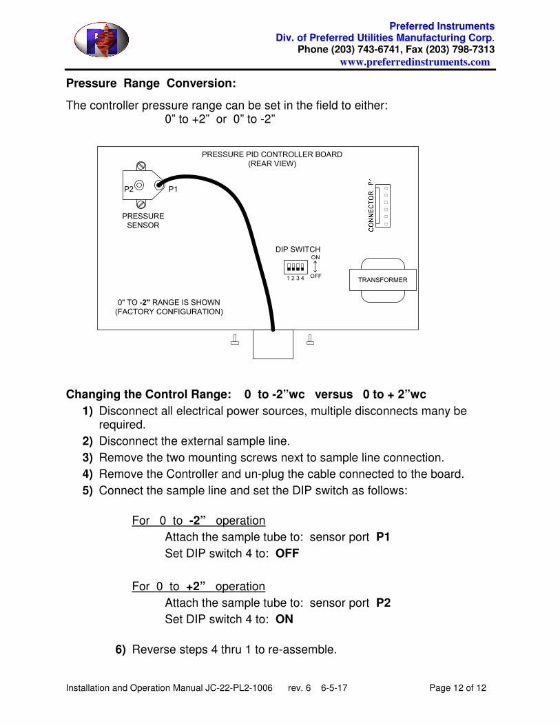
Pressure Range Conversion:
The controller pressure range can be set in the field to either: 0” to +2” or 0” to -2”
Changing the Control Range: 0 to -2”wc versus 0 to + 2”wc
1) Disconnect all electrical power sources, multiple disconnects many be required.
2) Disconnect the external sample line.
3) Remove the two mounting screws next to sample line connection.
4) Remove the Controller and un-plug the cable connected to the board.
5) Connect the sample line and set the DIP switch as follows:
For 0 to -2” operation
Attach the sample tube to: sensor port P1
Set DIP switch 4 to: OFF
For 0 to +2” operation
Attach the sample tube to: sensor port P2
Set DIP switch 4 to: ON
6) Reverse steps 4 thru 1 to re-assemble.
P2
TRANSFORMER
P1
PRESSURE
SENSOR
DIP SWITCH
PRESSURE PID CONTROLLER BOARD
(REAR VIEW)
0" TO -2" RANGE IS SHOWN
(FACTORY CONFIGURATION)
OFF
ON
1 2 3 4