Embed Size (px)
Citation preview
Darryl G. Thelen1
Department of Mechanical Engineering,
University of Wisconsin-Madison,
Madison, WI 53706;
Department of Biomedical Engineering,
University of Wisconsin-Madison,
Madison, WI 53706;
Department of Orthopedics and Rehabilitation,
University of Wisconsin-Madison,
Madison, WI 53706
e-mail: [email protected]
Kwang Won ChoiDepartment of Mechanical Engineering,
University of Wisconsin-Madison,
Madison, WI 53706
Anne M. SchmitzDepartment of Biomedical Engineering,
University of Wisconsin-Madison,
Madison, WI 53706
Co-Simulation of NeuromuscularDynamics and Knee MechanicsDuring Human WalkingThis study introduces a framework for co-simulating neuromuscular dynamics and kneejoint mechanics during gait. A knee model was developed that included 17 ligament bun-dles and a representation of the distributed contact between a femoral component andtibial insert surface. The knee was incorporated into a forward dynamics musculoskeletalmodel of the lower extremity. A computed muscle control algorithm was then used tomodulate the muscle excitations to drive the model to closely track measured hip, knee,and ankle angle trajectories of a subject walking overground with an instrumented kneereplacement. The resulting simulations predicted the muscle forces, ligament forces, sec-ondary knee kinematics, and tibiofemoral contact loads. Model-predicted tibiofemoralcontact forces were of comparable magnitudes to experimental measurements, with peakmedial (1.95 body weight (BW)) and total (2.76 BW) contact forces within 4–17% ofmeasured values. Average root-mean-square errors over a gait cycle were 0.26, 0.42,and 0.51 BW for the medial, lateral, and total contact forces, respectively. The modelwas subsequently used to predict variations in joint contact pressure that could arise byaltering the frontal plane joint alignment. Small variations (62 deg) in the alignment ofthe femoral component and tibial insert did not substantially affect the location of contactpressure, but did alter the medio-lateral distribution of load and internal tibia rotation inswing. Thus, the computational framework can be used to virtually assess the coupledinfluence of both physiological and design factors on in vivo joint mechanics and per-formance. [DOI: 10.1115/1.4026358]
Keywords: forward dynamics, computational biomechanics, knee contact forces, valida-tion, muscle forces
Introduction
The magnitude and location of joint contact forces are impor-tant to consider when assessing the causes and treatment of kneepathologies [1]. Since internal loads cannot normally be measuredin vivo, computational models are needed to estimate the jointcontact forces that can arise during functional tasks such as walk-ing. The traditional modeling approach involves two steps. A mul-tibody neuromuscular dynamics model is used in the first step toestimate the muscle and net joint forces associated with a task per-formance [2,3]. These forces are subsequently applied as bound-ary conditions to a knee mechanics model to estimate ligamentforces and the distribution of joint contact loads [4–6]. However,this serial simulation approach may not capture two-way interac-tions that can exist between musculoskeletal dynamics and inter-nal joint mechanics. In particular, musculoskeletal models used tosimulate movement typically use a simplified knee model withpre-assumed constraints on secondary knee motions [7–9]. Thisapproach assumes that contact forces do not induce momentsabout the primary joint axis and that muscle forces are not impor-tant contributors to secondary motion constraints [10]. However,the validity of such assumptions was questioned in a recent studythat showed that muscle force estimates are sensitive to the con-straints included in the knee model [10]. Hence, it would seempreferable to co-simulate neuromuscular dynamics and knee jointmechanics, such that the muscle, contact, and ligament loads are
considered within the context of whole body movementdynamics.
The co-simulation of movement and localized tissue mechanicsrepresents a computationally demanding problem that has onlyrecently been explored in the biomechanics literature [11,12]. Amajor challenge involves the computation of appropriate musclecontrols that drive a model to emulate coordinated movement.Prior studies have pre-assumed the muscle excitation patterns [13]or used dynamic optimization to compute muscle excitations thatachieve a desired performance criterion [11]. While dynamic opti-mization is an attractive approach, obtaining a global optimum canbe very challenging and require many iterations to converge [14].
We previously introduced a computed muscle control (CMC)algorithm which uses feedforward and feedback control to modu-late muscle excitations to track measured joint angle trajectories[15,16]. The CMC algorithm was originally formulated to workon models in which all joints have constrained translationaldegrees of freedom (e.g., a gimbal joint). Translational constraintsallow for instantaneous force transmission across the joint and,hence, a quantitative assessment of a muscle’s capacity to inducemovement throughout the body. However, in a dynamic multi-body model with 6 degree-of-freedom (d.o.f.) joints, time isrequired to deform the soft tissues and thereby transmit forcesacross a joint. Hence, the first objective of this study was to extendthe CMC algorithm to co-simulate musculoskeletal dynamics andjoint mechanics when using models that include 6 d.o.f. jointsspanned by soft tissues. Second, we sought to assess the veracityof the co-simulation framework by comparing the model predic-tions of knee contact forces to in vivo measures obtained with aninstrumented total knee joint replacement during walking [17].Finally, we demonstrate the capacity of the framework to assessthe sensitivity of contact loading patterns to variations in frontal
1Corresponding author.Contributed by the Bioengineering Division of ASME for publication in the
JOURNAL OF BIOMECHANICAL ENGINEERING. Manuscript received September 6, 2013;final manuscript received December 19, 2013; accepted manuscript postedDecember 26, 2013; published online February 5, 2014. Editor: Beth Winkelstein.
Journal of Biomechanical Engineering FEBRUARY 2014, Vol. 136 / 021033-1Copyright VC 2014 by ASME
Downloaded From: http://biomechanical.asmedigitalcollection.asme.org/ on 06/17/2014 Terms of Use: http://asme.org/terms
plane knee alignment, which is an important consideration in jointreplacement procedures.
Methods
Experimental Data. The experimental data used in this studywere collected as part of the 4th grand challenge competition forpredicting in vivo knee loads [17]. We simulated the gait of a malesubject (age 88 yr, mass¼ 68 kg, and height¼ 1.66 m) who receivedan instrumented total knee replacement on the right side for primaryosteoarthritis. The data downloaded from the competition website2
included the knee replacement geometry, post-operative CT scans,electromyographic data, whole body kinematics, ground reactions,and tibiofemoral contact forces during overgound walking. Medialand lateral tibiofemoral contact forces were delineated using fouruniaxial force transducers embedded in the tibial tray [18].
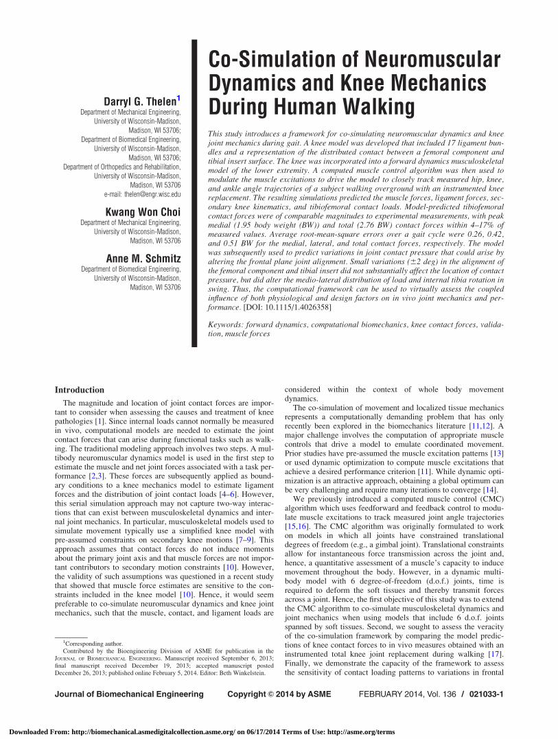
Knee Mechanics Model. We created a 3-body model of kneemechanics that included a 1 d.o.f. patellofemoral joint and a 6d.o.f. tibiofemoral joint [4,19]. Superior patella translation wasthe independent degree of freedom for the patellofemoral joint.The patellofemoral angles and anterior and lateral patella transla-tion were defined as constrained functions of superior translation,such that the patella could translate and rotate within a constrainedpath relative to the femur [9]. Seventeen knee ligament bundleswere included in the model (see Fig. 1): the patellar ligament(medial, mid, and lateral bundles), medial collateral ligament((MCL), 5 bundles), lateral collateral ligament (LCL), popliteofib-ular ligament (PFL), posterior cruciate ligament (anterior and pos-terior bundles), posterior capsule (4 bundles), and the illiotibialband (ITB). The anterior cruciate ligament (ACL) was notincluded since it was resected in the subject whose gait was simu-lated [17]. Ligament geometry data was not available for the testsubject, thus ligament origins and insertions were based on nomi-nal descriptions in the literature [20–25]. Wrapping objects wereaffixed to the femur to represent the collateral ligaments wrappingabout the condyles. The nonlinear relationship between the liga-ment force F‘ and strain e was represented by
F‘ ¼
0 e < 0
ke2
4e‘0 < e < 2e‘
k e� e‘ð Þ e > 2e‘
8>>><>>>:
(1)
where e‘ (¼0.03) is the transition strain and k is the ligament stiffnessexpressed in units of force per unit strain. At any time point, the liga-ment bundle strain e ¼ ðL� L0Þ=L0 was computed from the currentlength (L) and slack length (L0) of the ligament. The slack length of
each bundle was computed by scaling the ligament length in a refer-ence configuration with its assumed reference strain eref
L0 ¼ Lref=ð1þ erefÞ (2)The ligament stiffness and reference strains were adapted fromrepresentative values used in comparable knee models in the liter-ature [4,19] (see Table 1).
The geometry of the implanted femoral component and tibialinsert were represented by triangulated polygon meshes of thesubject’s joint replacement. The tibiofemoral contact loads werecomputed using an elastic foundation model in which pressurewas assumed to be a function of the depth of penetration of inter-secting bodies [27]. Intersecting regions between the femoral andtibia surface geometry were detected using ray casting in conjunc-tion with hierarchical bounding volumes. To do this, the femoralsurface was first subdivided into a tree of geometrically coherentsubsections and tight-fitting oriented bounding boxes (OBB) werefit over each subdivision [26]. A normal ray was then cast for eachtriangle of the tibia and a ray-OBB intersection test was per-formed with the largest OBB. If intersected, the ray-OBB testscontinued to subhierarchical levels, ultimately identifying the leafnode (single triangle) of the femoral surface intersected by the ray[26,28-30]. The penetration depth d was defined as the distancefrom the center of a tibia triangle to the point at which a normalray intersected the corresponding femoral leaf node. The contactpressure p on the tibia surface triangle was then calculated using alinearized version of an elastic foundation model [27]
p ¼ � 1� �ð ÞE1þ �ð Þ 1� 2�ð Þ
d
h(3)
where h is the insert thickness, � is Poisson’s ratio (¼0.46) and Eis Young’s modulus (¼463 MPa) for a ultrahigh molecular weightpolyethylene tibial insert [31]. The force acting on the tibia sur-face triangle was obtained by multiplying the pressure by the tri-angle cross-sectional area and applying the force normal to thetriangle. Equal and opposite forces were applied at the same pointin the femoral surface.
Fig. 1 The three body knee mechanics model included 17 liga-ment bundles acting about the tibiofemoral and patellofemoraljoints. Contact pressure between the femoral component andtibial insert was computed via an elastic foundation model. Lig-ament abbreviations are given in Table 1.
Table 1 Ligament stiffness and reference strains used in theknee mechanics model. A negative reference strain assumesthat the ligament is slack in the reference posture
Ligamenta Stiffness (N)b Reference strainc
aPCL 3000 �0.10pPCL 1500 �0.05asMCL 1500 0.02psMCL 1500 0.02adMCL 1000 0.02pdMCL 1000 0.02pMC 2000 0.02LCL 4000 0.02PFL 2000 �0.05aCAP 1500 0.02lCAP 2000 0.02oCAP 1500 0.02mCAP 2000 0.02mPL 4000 0.00cPL 4000 0.00lPL 4000 0.00ITB 5000 0.00
aNotation: aPCL/pPCL, anterior and posterior cruciate ligament; asMCLand ps MCL, anterior and posterior superior medial collateral ligament;adMCL and pdMCL, anterior and posterior deep medial collateral liga-ment; pMC, posteromedial capsule; LCL, lateral collateral ligament; PFL,popliteofibular ligament; aCAP, lCAP, oCAP, and mCAP, arcuate, politeallateral, medial, and oblique politeal bundles of posterior capsule; mPL, cPL,and lPL, medial, central, and lateral patellar ligament; ITB, ilitotibial band.bStiffness is expressed in units of force per unit strain.cReference strains are used to compute the ligament lengths in the uprightreference configuration.2See https://simtk.org/home/kneeloads for the competition data.
021033-2 / Vol. 136, FEBRUARY 2014 Transactions of the ASME
Downloaded From: http://biomechanical.asmedigitalcollection.asme.org/ on 06/17/2014 Terms of Use: http://asme.org/terms
Lower Extremity Musculoskeletal Model. We started with ageneric lower extremity musculoskeletal model [7] that includedthe pelvis, right femur, tibia, patella, and foot segments. The hipwas represented by a 3 d.o.f. ball-and-socket joint and the ankle asa 1 d.o.f. joint that allowed for dorsi- and plantarflexion. Wereplaced the 1 d.o.f. knee in the generic model with the 3-bodyknee model described earlier. The femoral component surface ge-ometry was positioned such that it closely aligned with the con-dyles of the generic model’s femur. The tibia insert surfacegeometry was then positioned in the tibia reference frame so thatit closely aligned with the femoral component when the modelwas in an upright standing posture. The lower extremity modelwas scaled to represent the subject. Each body segment was scaledsuch that anatomical landmarks were optimally aligned with ana-tomical marker positions recorded with the subject standingupright. During scaling, the frontal plane knee angle was fixed at4 deg valgus, as was measured from the post-operative CT scansof the subject.
The model included 44 Hill-type musculotendon units actingacross the hip, knee, and ankle joints [7]. The input to each musclewas an excitation that could vary between 0 and 1. Excitation-to-activation dynamics were represented by a bilinear differentialequation with activation and deactivation time constants of 15 and40 ms, respectively. The contraction dynamics was represented bya nonlinear differential equation describing the interaction of ten-don compliance and the force-length-velocity properties of muscle[33]. The lower extremity model was implemented in SIMM [34],with the Dynamics Pipeline (Musculographics Inc., Santa Rosa,CA) and SD/Fast (Parametric Technology Corp., Needham, MA)used to generate code describing the multibody equations ofmotion.
Computed Muscle Control Algorithm. With the muscles andknee model included, the multibody dynamic equations of motionare of the form
M€q ¼ RmFm þ R‘F‘ þ RcFc þ Fe þGðqÞ þ Cðq; _qÞ (4)
where M is the mass matrix, GðqÞ is a vector of forces arisingfrom gravity, Cðq; _qÞ are forces arising from the Coriolis and cen-tripetal accelerations, and Fe represents the generalized forcesarising from external loads or prescribed accelerations. The forcevectors arising from muscle (Fm), ligament (F‘), and articular con-tact (Fc) are scaled by the moment arm matrices Rm, R‘, and Rc,respectively. The generalized coordinates q include the 6 d.o.f.pelvis motion (translation and orientation) relative to ground,three hip rotation angles, three tibiofemoral angles, three tibife-moral translations, superior patella translation, and ankle dorsi-
flexion. The pelvis, hip, and tibiofemoral angles are expressed asa Cardan rotation sequence consisting of flexion, adduction, andthen rotation about the long axis of the distal segment [35].
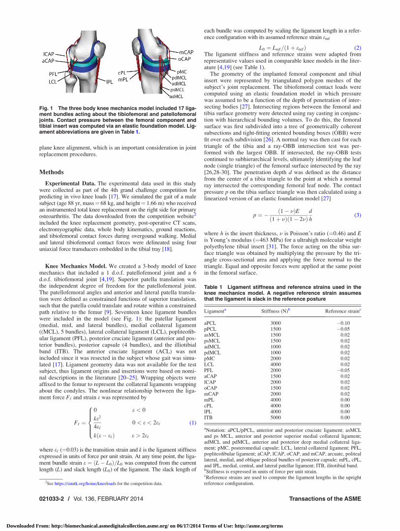
A computed muscle control (CMC) algorithm was used todetermine the muscle excitations needed to drive the model toclosely track the measured hip flexion, hip adduction, knee flex-ion, and ankle dorsiflexion trajectories (see Fig. 2). The CMC is afeedforward-feedback controller that uses the experimentallymeasured accelerations (€qexp) together with current errors in gen-eralized speeds ( _qexp� _q) and coordinates (qexp�q) to compute aset of desired generalized accelerations in the degrees of freedombeing tracked
€qdes ¼ €qexp þ kv _qexp � _qð Þ þ kp qexp�qð Þ (5)
where kv and kp are the velocity and position feedback gains,respectively.
The original formulation of the CMC was implemented for mul-tibody models in which all joints had constrained translationaldegrees of freedom, allowing for instantaneous load transfer acrossthe joint to occur. Such a formulation allows for a muscle’s poten-tial to induce motion, defined as the generalized accelerations gen-erated per unit muscle force [36], to be directly computed from thewhole body equations of motion. Computationally, muscle poten-tial is determined by applying a unit muscle force F̂i ¼ 1 and thensolving the equations of motion (see Eq. (4)) for the resultingaccelerations (€qi ¼M�1Rm
i ). However, in the case of a 6 d.o.f.tibiofemoral joint, it is not feasible for a muscle proximal to theknee to instantaneously generate segment accelerations distal tothe knee. Time is needed for ligament and contact surface defor-mations to occur, such that force is transmitted across the joint.To handle this challenge, we adapted CMC to compute amuscle’s potential to induce joint accelerations assuming the kneetranslational accelerations are instantaneously zero. This assump-tion was used since contact and ligament forces restrict the kneetranslations to relatively small magnitudes. A zero translationalacceleration constraint therefore allowed for instantaneous forcetransmission across the knee and, thus, provided an estimate ofthe effect of ligament and contact forces on joint rotational accel-erations. To implement the constraint, we first defined a vector qxas the subset of generalized coordinates associated with the tibio-femoral (qtx, qty, qtz) and patellofemoral (qpy) translationaldegrees of freedom
qx¼ qtx qty qtz qpy½ �T (6)
We used a finite difference technique to estimate a sensitivity ma-trix Sx describing the dependency of generalized accelerations tovariations in the knee translational degrees of freedom
Fig. 2 A computed muscle control (CMC) algorithm was used to modulate thelower limb muscle excitations such that the simulation closely tracked the meas-ured hip, knee, and ankle angles. At every time step, the tibia, patella, and femurpositions were used to ascertain the tibiofemoral contact and ligament forces.These forces were then applied within the forward dynamic simulation of the neuro-musculoskeletal model.
Journal of Biomechanical Engineering FEBRUARY 2014, Vol. 136 / 021033-3
Downloaded From: http://biomechanical.asmedigitalcollection.asme.org/ on 06/17/2014 Terms of Use: http://asme.org/terms
Sx ¼@€q
@qtx
@€q
@qty
@€q
@qtz
@€q
@qpy
� �(7)
These sensitivities were then used to determine virtual perturba-tions dqx to the translation knee coordinates that, in conjunctionwith a unit muscle force, would negate translational knee acceler-ations. This assumption was applied for each muscle i by solvingthe following linear equations
€̂qi¼M�1Rmi þSxdqx;i (8)
€̂qx ¼ 0 (9)
for dqx;i and €̂qi. The vector €̂qi is an estimate of the potential ofmuscle i to induce accelerations throughout the limb per unit mus-cle force.
The muscle potential acceleration information was used toupdate muscle controls every T¼ 0.01 s within a simulation.When updating controls, we first determined muscle force incre-ments dFm that, when added to the current muscle forces, wouldinduce desired accelerations in the tracked degrees of freedom
€qdes ¼Xn
i¼1
dFmi €̂qi þ €qcur (10)
In Eq. (10), n is the number of muscles and €qcur represent the gen-eralized accelerations resulting from current muscle forces, liga-ment forces, contact forces, external force and gravity acting onthe system. Muscle redundancy was resolved by simultaneouslyminimizing a cost function J which, in this study, was taken as thesum of muscle-volume (V) weighted squared activations (a) [37]
J¼Xn
i¼1
Via2i (11)
where muscle activations are determined based on the force-length-activation properties of muscle [15]. Excitations were thendetermined from the activations by inverting activation dynamics.After computing the controls, the skeletal equations of motion,muscle activation dynamics, and contraction dynamics were inte-grated forward using a forward-backwards implicit numericalintegration routine [32]. The control process was then repeatedevery T¼ 0.01 s throughout a gait simulation.
Simulations of Knee Mechanics During Gait. We generatedsimulations of five overground walking trials with an average gaitspeed of 1.25 (60.02) m/s. For each gait trial, a global optimizationinverse kinematics routine was first used to determine the pelvistranslations, pelvis rotation, hip angles, knee flexion, and ankle dorsi-flexion that best agreed with the measured pelvis and lower extrem-ity marker trajectories. At this stage, the knee abduction angle wasmaintained at 4� while the tibiofemoral internal rotation and transla-tions were assumed to be constrained functions of knee flexion asdefined in the generic lower extremity model of Arnold et al. [7].
We then used the CMC algorithm to compute muscle excita-tions that drove the dynamic multibody model to track the meas-ured hip flexion, hip adduction, knee flexion, and ankledorsiflexion trajectories over a gait cycle. Measured ground reac-tions were applied directly on the feet [15], while pelvis general-ized coordinates were prescribed to track measured values. Thetibiofemoral translations, patellofemoral translation, tibiofemoralinternal rotation, and tibiofemoral adduction were unconstrainedin the dynamic simulations and, thus, evolved naturally as a func-tion of the external and internal loads acting on the system. Wecompared the timing of the muscle excitations to temporal pat-terns of electromyographic data that were recorded from the sub-ject during the simulated walking trials. Model predictions oftibiofemoral contact forces acting in the medial and lateral com-partments were quantitatively compared to in vivo measures using
Pearson’s correlation, the coefficient of determination, the averagedifference in the force predictions (bias), the standard deviation ofthe force prediction errors (precision), and the root-mean-squared(RMS) error. We also evaluated the agreement between themedial, lateral, and total contact forces at the time of the two peakcontact forces that arise in the stance phase of normal gait.
Sensitivity of Model Predictions to Frontal Plane Align-ment. We performed a sensitivity study analyzing the dependenceof tibiofemoral loading patterns to variations in frontal planealignment between the femoral component and tibia insert. To dothis, we first re-ran the inverse kinematics routine with fixed kneevalgus angles 2 deg greater and less than that measured (4 deg val-gus) on the CT scans. For each case, we re-oriented the femoralcomponent and tibia insert by counter-rotating each surface by1 deg in the coronal plane, such that they were aligned and justcontacting with the model in the upright standing configuration.We then used the CMC to regenerate dynamic simulations usingthe re-aligned models to track the gait kinematics. Note that tibio-femoral adduction and rotation were not fixed in these forwarddynamic simulations, but evolved as a result of tibiofemoral con-tact and internal soft tissue loadings. The effect of alignment onloading was quantitatively evaluated by comparing the tibiofe-moral contact force and pressure patterns at heel strike and thetime of the first and second peak of the tibiofemoral contact force.
Results
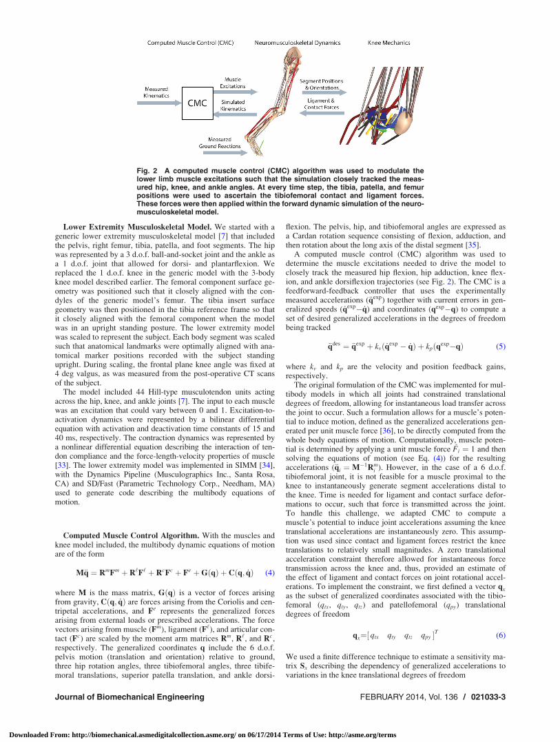
The modified CMC algorithm modulated muscle excitation pat-terns (see Fig. 3) to successfully track the measured hip flexion,hip adduction, knee flexion, and ankle angle trajectories with av-erage root-mean-square errors of 0.4 deg, 0.3 deg, 0.9 deg, and1.0 deg respectively. Simulated posterior cruciate and collateralligament forces were relatively small (generally <100 N), withpeak magnitudes arising during swing phase (see Fig. 3).
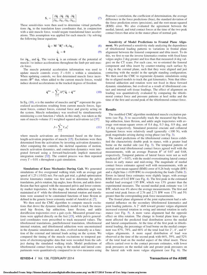
The model predictions of the tibiofemoral contact forces exhib-ited the characteristic double peak in stance, with a greater loadborne on the medial side (see Fig. 3). The temporal patterns ofmedial and total tibiofemoroal contact forces agreed well with themeasurements, with an average Pearson R2 of 0.87 and 0.68,respectively. Temporal patterns of lateral forces were not as wellpredicted (R2¼ 0.07), with the model overestimating lateral contactforces in early stance and mid-swing. The magnitude of medialcontact forces estimates agreed well with measurements, with anaverage root-mean-squared (RMS) error of 0.26 body weight (BW)and a slight bias (þ0.09 BW) to overpredicting the loads (Table 2).Errors in lateral force estimates were slightly larger, with averageRMS errors of 0.42 BW (see Fig. 4). The first peak in the estimatedmedial load averaged 1.95 BW, which was 13% greater than theexperimental measures. The second medial peak estimate was 1.6BW, which was 4% above the average measurements. The first andsecond total peak forces of 2.76 and 2.71 BW were 17% and 5%greater than the corresponding peak force measurements.
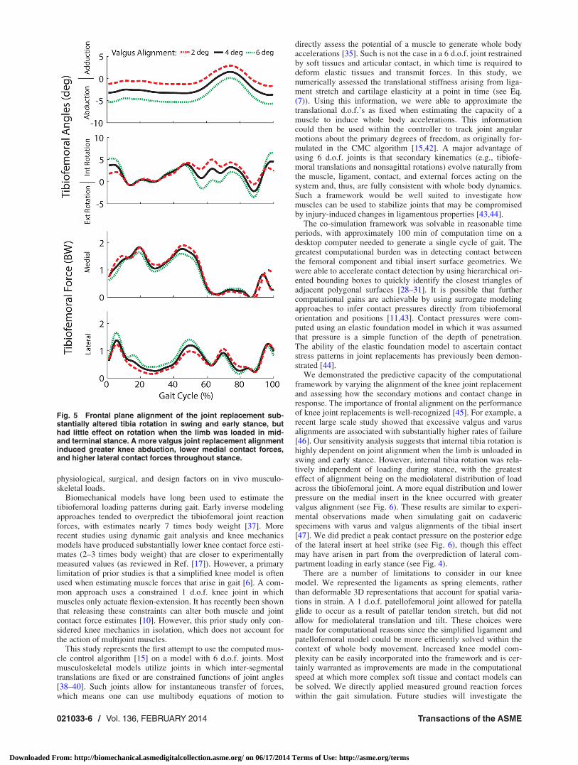
The frontal plane alignment of the joint replacement had a sub-stantial influence on the secondary tibiofemoral kinematics andjoint loading patterns. A 2� shift toward greater valgus alignmentincreased external rotation in swing and internal rotation in earlystance (see Fig. 5). A more varus alignment had the oppositeeffect on tibia rotation. The change in frontal plane knee align-ment affected the predicted load distribution across the medialand lateral compartments. At the time of the first peak in tibiofe-moral loading, the percentage of load borne on the medial compo-nent was 87%, 78%, and 66% of the total load for 2�, 4�, and 6�
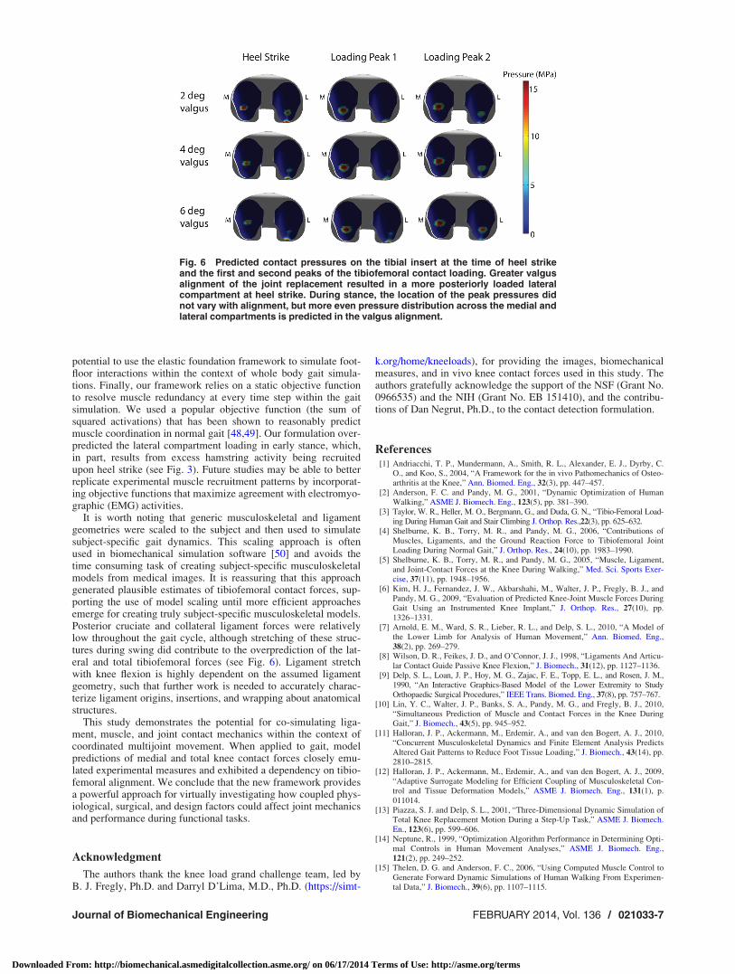
valgus alignments. A more equal distribution of load wasobserved at the time of the second peak with 66%, 59%, and 52%of the total load on the medial aspect of the tibial insert. Theseeffects carried over to the contact pressure estimates, with lowerpeak pressures on the medial side and greater peak pressures onthe lateral side with more valgus alignment (see Fig. 6). The
021033-4 / Vol. 136, FEBRUARY 2014 Transactions of the ASME
Downloaded From: http://biomechanical.asmedigitalcollection.asme.org/ on 06/17/2014 Terms of Use: http://asme.org/terms
coronal alignment affected the location of pressure at heel strike,but did not substantially alter the location of peak pressure regionswhen the limb was loaded in mid-stance.
Discussion
We have introduced a framework for simulating the interactionof muscle, ligament, and joint contact forces within the context ofdynamic multijoint movement. We first showed that the frame-work can be used to predict knee contact force patterns that com-pare well with those measured directly using an instrumentedknee implant [18]. We then demonstrated that the co-simulation
framework can be used to predict the sensitivity of knee contactloading patterns to variations in implant alignment. Such anapproach allows one to virtually assess the coupled influence of
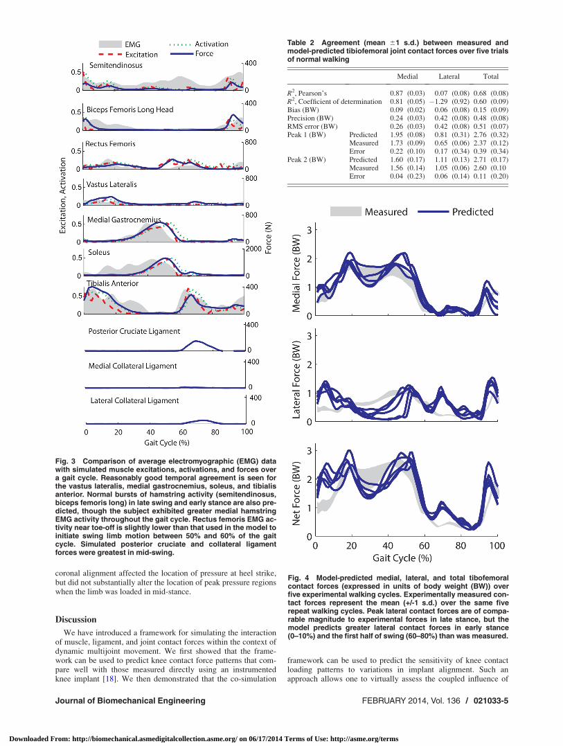
Table 2 Agreement (mean 61 s.d.) between measured andmodel-predicted tibiofemoral joint contact forces over five trialsof normal walking
Medial Lateral Total
R2, Pearson’s 0.87 (0.03) 0.07 (0.08) 0.68 (0.08)R2, Coefficient of determination 0.81 (0.05) �1.29 (0.92) 0.60 (0.09)Bias (BW) 0.09 (0.02) 0.06 (0.08) 0.15 (0.09)Precision (BW) 0.24 (0.03) 0.42 (0.08) 0.48 (0.08)RMS error (BW) 0.26 (0.03) 0.42 (0.08) 0.51 (0.07)Peak 1 (BW) Predicted 1.95 (0.08) 0.81 (0.31) 2.76 (0.32)
Measured 1.73 (0.09) 0.65 (0.06) 2.37 (0.12)Error 0.22 (0.10) 0.17 (0.34) 0.39 (0.34)
Peak 2 (BW) Predicted 1.60 (0.17) 1.11 (0.13) 2.71 (0.17)Measured 1.56 (0.14) 1.05 (0.06) 2.60 (0.10Error 0.04 (0.23) 0.06 (0.14) 0.11 (0.20)
Fig. 4 Model-predicted medial, lateral, and total tibofemoralcontact forces (expressed in units of body weight (BW)) overfive experimental walking cycles. Experimentally measured con-tact forces represent the mean (+/-1 s.d.) over the same fiverepeat walking cycles. Peak lateral contact forces are of compa-rable magnitude to experimental forces in late stance, but themodel predicts greater lateral contact forces in early stance(0–10%) and the first half of swing (60–80%) than was measured.
Fig. 3 Comparison of average electromyographic (EMG) datawith simulated muscle excitations, activations, and forces overa gait cycle. Reasonably good temporal agreement is seen forthe vastus lateralis, medial gastrocnemius, soleus, and tibialisanterior. Normal bursts of hamstring activity (semitendinosus,biceps femoris long) in late swing and early stance are also pre-dicted, though the subject exhibited greater medial hamstringEMG activity throughout the gait cycle. Rectus femoris EMG ac-tivity near toe-off is slightly lower than that used in the model toinitiate swing limb motion between 50% and 60% of the gaitcycle. Simulated posterior cruciate and collateral ligamentforces were greatest in mid-swing.
Journal of Biomechanical Engineering FEBRUARY 2014, Vol. 136 / 021033-5
Downloaded From: http://biomechanical.asmedigitalcollection.asme.org/ on 06/17/2014 Terms of Use: http://asme.org/terms
physiological, surgical, and design factors on in vivo musculo-skeletal loads.
Biomechanical models have long been used to estimate thetibiofemoral loading patterns during gait. Early inverse modelingapproaches tended to overpredict the tibiofemoral joint reactionforces, with estimates nearly 7 times body weight [37]. Morerecent studies using dynamic gait analysis and knee mechanicsmodels have produced substantially lower knee contact force esti-mates (2–3 times body weight) that are closer to experimentallymeasured values (as reviewed in Ref. [17]). However, a primarylimitation of prior studies is that a simplified knee model is oftenused when estimating muscle forces that arise in gait [6]. A com-mon approach uses a constrained 1 d.o.f. knee joint in whichmuscles only actuate flexion-extension. It has recently been shownthat releasing these constraints can alter both muscle and jointcontact force estimates [10]. However, this prior study only con-sidered knee mechanics in isolation, which does not account forthe action of multijoint muscles.
This study represents the first attempt to use the computed mus-cle control algorithm [15] on a model with 6 d.o.f. joints. Mostmusculoskeletal models utilize joints in which inter-segmentaltranslations are fixed or are constrained functions of joint angles[38–40]. Such joints allow for instantaneous transfer of forces,which means one can use multibody equations of motion to
directly assess the potential of a muscle to generate whole bodyaccelerations [35]. Such is not the case in a 6 d.o.f. joint restrainedby soft tissues and articular contact, in which time is required todeform elastic tissues and transmit forces. In this study, wenumerically assessed the translational stiffness arising from liga-ment stretch and cartilage elasticity at a point in time (see Eq.(7)). Using this information, we were able to approximate thetranslational d.o.f.’s as fixed when estimating the capacity of amuscle to induce whole body accelerations. This informationcould then be used within the controller to track joint angularmotions about the primary degrees of freedom, as originally for-mulated in the CMC algorithm [15,42]. A major advantage ofusing 6 d.o.f. joints is that secondary kinematics (e.g., tibiofe-moral translations and nonsagittal rotations) evolve naturally fromthe muscle, ligament, contact, and external forces acting on thesystem and, thus, are fully consistent with whole body dynamics.Such a framework would be well suited to investigate howmuscles can be used to stabilize joints that may be compromisedby injury-induced changes in ligamentous properties [43,44].
The co-simulation framework was solvable in reasonable timeperiods, with approximately 100 min of computation time on adesktop computer needed to generate a single cycle of gait. Thegreatest computational burden was in detecting contact betweenthe femoral component and tibial insert surface geometries. Wewere able to accelerate contact detection by using hierarchical ori-ented bounding boxes to quickly identify the closest triangles ofadjacent polygonal surfaces [28–31]. It is possible that furthercomputational gains are achievable by using surrogate modelingapproaches to infer contact pressures directly from tibiofemoralorientation and positions [11,43]. Contact pressures were com-puted using an elastic foundation model in which it was assumedthat pressure is a simple function of the depth of penetration.The ability of the elastic foundation model to ascertain contactstress patterns in joint replacements has previously been demon-strated [44].
We demonstrated the predictive capacity of the computationalframework by varying the alignment of the knee joint replacementand assessing how the secondary motions and contact change inresponse. The importance of frontal alignment on the performanceof knee joint replacements is well-recognized [45]. For example, arecent large scale study showed that excessive valgus and varusalignments are associated with substantially higher rates of failure[46]. Our sensitivity analysis suggests that internal tibia rotation ishighly dependent on joint alignment when the limb is unloaded inswing and early stance. However, internal tibia rotation was rela-tively independent of loading during stance, with the greatesteffect of alignment being on the mediolateral distribution of loadacross the tibiofemoral joint. A more equal distribution and lowerpressure on the medial insert in the knee occurred with greatervalgus alignment (see Fig. 6). These results are similar to experi-mental observations made when simulating gait on cadavericspecimens with varus and valgus alignments of the tibial insert[47]. We did predict a peak contact pressure on the posterior edgeof the lateral insert at heel strike (see Fig. 6), though this effectmay have arisen in part from the overprediction of lateral com-partment loading in early stance (see Fig. 4).
There are a number of limitations to consider in our kneemodel. We represented the ligaments as spring elements, ratherthan deformable 3D representations that account for spatial varia-tions in strain. A 1 d.o.f. patellofemoral joint allowed for patellaglide to occur as a result of patellar tendon stretch, but did notallow for mediolateral translation and tilt. These choices weremade for computational reasons since the simplified ligament andpatellofemoral model could be more efficiently solved within thecontext of whole body movement. Increased knee model com-plexity can be easily incorporated into the framework and is cer-tainly warranted as improvements are made in the computationalspeed at which more complex soft tissue and contact models canbe solved. We directly applied measured ground reaction forceswithin the gait simulation. Future studies will investigate the
Fig. 5 Frontal plane alignment of the joint replacement sub-stantially altered tibia rotation in swing and early stance, buthad little effect on rotation when the limb was loaded in mid-and terminal stance. A more valgus joint replacement alignmentinduced greater knee abduction, lower medial contact forces,and higher lateral contact forces throughout stance.
021033-6 / Vol. 136, FEBRUARY 2014 Transactions of the ASME
Downloaded From: http://biomechanical.asmedigitalcollection.asme.org/ on 06/17/2014 Terms of Use: http://asme.org/terms
potential to use the elastic foundation framework to simulate foot-floor interactions within the context of whole body gait simula-tions. Finally, our framework relies on a static objective functionto resolve muscle redundancy at every time step within the gaitsimulation. We used a popular objective function (the sum ofsquared activations) that has been shown to reasonably predictmuscle coordination in normal gait [48,49]. Our formulation over-predicted the lateral compartment loading in early stance, which,in part, results from excess hamstring activity being recruitedupon heel strike (see Fig. 3). Future studies may be able to betterreplicate experimental muscle recruitment patterns by incorporat-ing objective functions that maximize agreement with electromyo-graphic (EMG) activities.
It is worth noting that generic musculoskeletal and ligamentgeometries were scaled to the subject and then used to simulatesubject-specific gait dynamics. This scaling approach is oftenused in biomechanical simulation software [50] and avoids thetime consuming task of creating subject-specific musculoskeletalmodels from medical images. It is reassuring that this approachgenerated plausible estimates of tibiofemoral contact forces, sup-porting the use of model scaling until more efficient approachesemerge for creating truly subject-specific musculoskeletal models.Posterior cruciate and collateral ligament forces were relativelylow throughout the gait cycle, although stretching of these struc-tures during swing did contribute to the overprediction of the lat-eral and total tibiofemoral forces (see Fig. 6). Ligament stretchwith knee flexion is highly dependent on the assumed ligamentgeometry, such that further work is needed to accurately charac-terize ligament origins, insertions, and wrapping about anatomicalstructures.
This study demonstrates the potential for co-simulating liga-ment, muscle, and joint contact mechanics within the context ofcoordinated multijoint movement. When applied to gait, modelpredictions of medial and total knee contact forces closely emu-lated experimental measures and exhibited a dependency on tibio-femoral alignment. We conclude that the new framework providesa powerful approach for virtually investigating how coupled phys-iological, surgical, and design factors could affect joint mechanicsand performance during functional tasks.
Acknowledgment
The authors thank the knee load grand challenge team, led byB. J. Fregly, Ph.D. and Darryl D’Lima, M.D., Ph.D. (https://simt-
k.org/home/kneeloads), for providing the images, biomechanicalmeasures, and in vivo knee contact forces used in this study. Theauthors gratefully acknowledge the support of the NSF (Grant No.0966535) and the NIH (Grant No. EB 151410), and the contribu-tions of Dan Negrut, Ph.D., to the contact detection formulation.
References[1] Andriacchi, T. P., Mundermann, A., Smith, R. L., Alexander, E. J., Dyrby, C.
O., and Koo, S., 2004, “A Framework for the in vivo Pathomechanics of Osteo-arthritis at the Knee,” Ann. Biomed. Eng., 32(3), pp. 447–457.
[2] Anderson, F. C. and Pandy, M. G., 2001, “Dynamic Optimization of HumanWalking,” ASME J. Biomech. Eng., 123(5), pp. 381–390.
[3] Taylor, W. R., Heller, M. O., Bergmann, G., and Duda, G. N., “Tibio-Femoral Load-ing During Human Gait and Stair Climbing J. Orthop. Res.,22(3), pp. 625–632.
[4] Shelburne, K. B., Torry, M. R., and Pandy, M. G., 2006, “Contributions ofMuscles, Ligaments, and the Ground Reaction Force to Tibiofemoral JointLoading During Normal Gait,” J. Orthop. Res., 24(10), pp. 1983–1990.
[5] Shelburne, K. B., Torry, M. R., and Pandy, M. G., 2005, “Muscle, Ligament,and Joint-Contact Forces at the Knee During Walking,” Med. Sci. Sports Exer-cise, 37(11), pp. 1948–1956.
[6] Kim, H. J., Fernandez, J. W., Akbarshahi, M., Walter, J. P., Fregly, B. J., andPandy, M. G., 2009, “Evaluation of Predicted Knee-Joint Muscle Forces DuringGait Using an Instrumented Knee Implant,” J. Orthop. Res., 27(10), pp.1326–1331.
[7] Arnold, E. M., Ward, S. R., Lieber, R. L., and Delp, S. L., 2010, “A Model ofthe Lower Limb for Analysis of Human Movement,” Ann. Biomed. Eng.,38(2), pp. 269–279.
[8] Wilson, D. R., Feikes, J. D., and O’Connor, J. J., 1998, “Ligaments And Articu-lar Contact Guide Passive Knee Flexion,” J. Biomech., 31(12), pp. 1127–1136.
[9] Delp, S. L., Loan, J. P., Hoy, M. G., Zajac, F. E., Topp, E. L., and Rosen, J. M.,1990, “An Interactive Graphics-Based Model of the Lower Extremity to StudyOrthopaedic Surgical Procedures,” IEEE Trans. Biomed. Eng., 37(8), pp. 757–767.
[10] Lin, Y. C., Walter, J. P., Banks, S. A., Pandy, M. G., and Fregly, B. J., 2010,“Simultaneous Prediction of Muscle and Contact Forces in the Knee DuringGait,” J. Biomech., 43(5), pp. 945–952.
[11] Halloran, J. P., Ackermann, M., Erdemir, A., and van den Bogert, A. J., 2010,“Concurrent Musculoskeletal Dynamics and Finite Element Analysis PredictsAltered Gait Patterns to Reduce Foot Tissue Loading,” J. Biomech., 43(14), pp.2810–2815.
[12] Halloran, J. P., Ackermann, M., Erdemir, A., and van den Bogert, A. J., 2009,“Adaptive Surrogate Modeling for Efficient Coupling of Musculoskeletal Con-trol and Tissue Deformation Models,” ASME J. Biomech. Eng., 131(1), p.011014.
[13] Piazza, S. J. and Delp, S. L., 2001, “Three-Dimensional Dynamic Simulation ofTotal Knee Replacement Motion During a Step-Up Task,” ASME J. Biomech.En., 123(6), pp. 599–606.
[14] Neptune, R., 1999, “Optimization Algorithm Performance in Determining Opti-mal Controls in Human Movement Analyses,” ASME J. Biomech. Eng.,121(2), pp. 249–252.
[15] Thelen, D. G. and Anderson, F. C., 2006, “Using Computed Muscle Control toGenerate Forward Dynamic Simulations of Human Walking From Experimen-tal Data,” J. Biomech., 39(6), pp. 1107–1115.
Fig. 6 Predicted contact pressures on the tibial insert at the time of heel strikeand the first and second peaks of the tibiofemoral contact loading. Greater valgusalignment of the joint replacement resulted in a more posteriorly loaded lateralcompartment at heel strike. During stance, the location of the peak pressures didnot vary with alignment, but more even pressure distribution across the medial andlateral compartments is predicted in the valgus alignment.
Journal of Biomechanical Engineering FEBRUARY 2014, Vol. 136 / 021033-7
Downloaded From: http://biomechanical.asmedigitalcollection.asme.org/ on 06/17/2014 Terms of Use: http://asme.org/terms
[16] Thelen, D. G., Anderson, F. C., and Delp, S. L., 2003, “Generating DynamicSimulations of Movement Using Computed Muscle Control,” J. Biomech.,36(3), pp. 321–328.
[17] Fregly, B. J., Besier, T. F., Lloyd, D. G., Delp, S. L., Banks, S. A., Pandy, M.G., and D’Lima, D. D., 2012, “Grand Challenge Competition to Predict in vivoKnee Loads,” J. Orthop. Res., 30(4), pp. 503–513.
[18] D’Lima, D. D., Townsend, C. P., Arms, S. W., Morris, B. A., Colwell, C. W.Jr., 2005, “An Implantable Telemetry Device to Measure Intra-Articular TibialForces,” J. Biomech., 38(2), pp. 299–304.
[19] Shin, C. S., Chaudhari, A. M., and Andriacchi, T. P., 2007, “The Influence ofDeceleration Forces on ACL Strain During Single-Leg Landing: A SimulationStudy,” J. Biomech., 40(5), pp. 1145–1152.
[20] Davies, H., Unwin, A., and Aichroth, P., 2004, “The Posterolateral Corner ofthe Knee: Anatomy, Biomechanics and Management of Injuries,” Injury, 35(1),pp. 68–75.
[21] Edwards, A., Bull, A. M., and Amis, A. A., 2007, “The Attachments of theFiber Bundles of the Posterior Cruciate Ligament: An Anatomic Study,”Arthroscopy, 23(3), pp. 284–290.
[22] Petersen, W. M. D., and Zantop, T. M. D., 2007, “Anatomy of the Anterior Cru-ciate Ligament with Regard to Its Two Bundles,” Clin. Orthop. Relat. Res.,454, pp. 35–47.
[23] Sugita, T., and Amis, A. A., 2001, “Anatomic and Biomechanical Study of theLateral Collateral and Popliteofibular Ligaments,” Am. J. Sports Med., 29(4),pp. 466–472.
[24] Liu, F., Yue, B., Gadikota, H. R., Kozanek, M., Liu, W., Gill, T. J., Rubash, H.E., and Li, G., 2010, “Morphology of the Medial Collateral Ligament of theKnee,” J. Orthop. Surg. Res., 5, p. 69.
[25] LaPrade, R. F., Ly, T. V., Wentorf, F. A., and Engebretsen, L., 2003, “The Pos-terolateral Attachments of the Knee: A Qualitative and Quantitative Morpho-logic Analysis of the Fibular Collateral Ligament, Popliteus Tendon,Popliteofibular Ligament, and Lateral Gastrocnemius Tendon,” Am. J. SportsMed., 31(6), p. 854–860.
[26] van den Bergen, G., 2003, Collision Detection in Interactive 3D Environments,Morgan Kaufmann Publishers, an Imprint of Elsevier, San Francisco, CA, pp.192–209.
[27] Bei, Y. and Fregly, B. J., 2004, “Multibody Dynamic Simulation of Knee Con-tact Mechanics,’ Med. Eng. Phys., 26(9), p. 777–789.
[28] Gottschalk, S., Lin, M. C., and Manocha, D., 1996, “OBBTree: A HierarchicalStructure for Rapid Interference Detection,” SIGGRAPH ’96 Proceedings ofthe 23rd annual conference on Computer graphics and interactive techniques,pp. 171–180.
[29] Schmidl, H., Walker, N., Lin, M., 2004, “CAB: Fast Update of OBB Trees forCollision Detection Between Articulated Bodies,” J. Graph. Tool, 9, pp. 1–9.
[30] Kurt, S. M., Jewett, C. W., Bergstrom, J. S., Foulds, J. R., and Edidin, A. A.,2002, “Miniature Specimen Shear Punch Test for UHMWPE Used in TotalJoint Replacements,” Biomaterials, 23(9), pp. 1907–1919.
[31] Hindmarsh, A. C., Brown, P. N., Grant, K. E., Lee, S. L., Serban, R., Shumaker, D.E., and Woodward, C. S., 2005, “SUNDIALS: Suite of Nonlinear and Differential/Algebraic Equation Solvers,” ACM Trans. Math. Softw., 31(3), pp. 363–396.
[32] Thelen, D. G., 2003, “Adjustment of Muscle Mechanics Model Parameters toSimulate Dynamic Contractions in Older Adults,” ASME J. Biomech. Eng.,125(1), pp. 70–77.
[33] Delp, S. L. and Loan, J. P., 1995, “A Graphics-Based Software System to De-velop and Analyze Models of Musculoskeletal Structures,” Comput. Biol.Med., 25(1), pp. 21–34.
[34] Grood, E. S. and Suntay, W. J., 1983, “A Joint Coordinate System for the Clini-cal Description of Three-Dimensional Motions: Application to the Knee,”ASME J. Biomech. Eng., 105(2), pp. 136–144.
[35] Arnold, A. S., Anderson, F. C., Pandy, M. G., and Delp, S. L., 2005, “MuscularContributions to Hip and Knee Extension During the Single Limb Stance Phaseof Normal Gait: A Framework for Investigating the Causes of Crouch Gait,” J.Biomech., 38(11), pp. 2181–2189.
[36] Happee, R., 1994, “Inverse Dynamic Optimization Including Muscular Dynam-ics, a New Simulation Method Applied to Goal Directed Movements,” J. Bio-mech., 27(7), p. 953–960.
[37] Seireg, A., and Arvikar, R. J., 1975, “The Prediction of Muscular Lad Sharingand Joint Forces in the Lower Extremities During Walking,” J. Biomech., 8(2),pp. 89–102.
[38] Wilson, D., and O’Connor, J., 1997, “A Three-Dimensional Geometric Modelof the Knee for the Study of Joint Forces in Gait,” Gait and Posture, 5(2), pp.108–115.
[39] Yamaguchi, G. T. and Zajac, F. E., 1989, “A Planar Model of the Knee Joint toCharacterize the Knee Extensor Mechanism,” J. Biomech., 22, p. 1–10.
[40] Thelen, D. G., Anderson, F. C., and Delp, S. L., 2003, “Generating DynamicSimulations of Movement Using Computed Muscle Control,” J. Biomech.,36(3), p. 321–328.
[41] Shelburne, K. B., Torry, M. R., and Pandy, M. G., 2005, “Effect of MuscleCompensation on Knee Instability During ACL-Deficient Gait,” Med. Sci.Sports Exercise, 37(4), pp. 642–648.
[42] Shao, Q., MacLeod, T. D., Manal, K., and Buchanan, T. S., 2011, “Estimationof Ligament Loading and Anterior Tibial Translation in Healthy and ACL-Deficient Knees During Gait and the Influence of Increasing Tibial Slope UsingEMG-Driven Approach,” Ann. Biomed. Eng., 39(1), pp. 110–121.
[43] Lin, Y. C., Farr, J., Carter, K., and Fregly, B. J., 2006, “Response Surface Optimiza-tion for Joint Contact Model Evaluation,” J. Appl. Biomech., 22(2), pp. 120–130.
[44] Halloran, J. P., Petrella, A. J., Rullkoetter, P. J., Easley, S. K., Anthony J. Pet-rella, Paul J. Rullkoetter and Sarah K. Easley, 2005, “Comparison of Deforma-ble and Elastic Foundation Finite Element Simulations for Predicting KneeReplacement Mechanics,” ASME J. Biomech. Eng., 127(5), pp. 813–818.
[45] Jeffery, R. S., Morris, R. W., and Denham, R. A., 1991, “Coronal AlignmentAfter Total Knee Replacement,” J. Bone Jt. Surg., Br. Vol., 73(5), pp. 709–714.
[46] Fang, D. M., Ritter, M. A., and Davis, K. W., 2009, “Coronal Alignment in TotalKnee Arthroplasty: Just How Important is It?,” J. Arthroplasty, 24(6), pp. 39–43.
[47] Werner, F. W., Ayers, D. C., Maletsky, L. P., and Rullkoetter, P. J., 2005, “TheEffect of Valgus/Varus Malalignment on Load Distribution in Total KneeReplacements,” J. Biomech., 38(2), pp. 349–355.
[48] Crowninshield, R. D. and Brand, R. A., 1981, “A Physiologically Based Criterionof Muscle Force Prediction in Locomotion,” J. Biomech., 14(11), pp. 793–801.
[49] Anderson, F. C. and Pandy, M. G., 2001, “Static and Dynamic OptimizationSolutions for Gait are Practically Equivalent,” J. Biomech., 34(2), pp. 153–161.
[50] Delp, S. L., Anderson, F. C., Arnold, A.S., Loan, P., Habib, A., John, C. T.,Guendelman, E., Thelen, D. G., 2007, “OpenSim: Open-Source Software toCreate and Analyze Dynamic Simulations of Movement,” IEEE Trans. Biomed.Eng., 54(11), pp. 1940–1950.
021033-8 / Vol. 136, FEBRUARY 2014 Transactions of the ASME
Downloaded From: http://biomechanical.asmedigitalcollection.asme.org/ on 06/17/2014 Terms of Use: http://asme.org/terms


