Embed Size (px)
Citation preview
Supporting Legacy Applications over i3
Jayanthkumar Kannan Ayumu Kubota Karthik LakshminarayananUniv. of California, Berkeley KDDI Labs Univ. of California, Berkeley
Ion Stoica Klaus WehrleUniv. of California, Berkeley Univ. of Tubingen
Report No. UCB/CSD-04-1342
June 2004
Computer Science Division (EECS)University of CaliforniaBerkeley, California 94720
Supporting Legacy Applications over i3
Jayanthkumar Kannan Ayumu Kubota Karthik LakshminarayananUniv. of California, Berkeley KDDI Labs Univ. of California, Berkeley
Ion Stoica Klaus WehrleUniv. of California, Berkeley Univ. of T¨ubingen
June 2004
Abstract
Providing support for legacy applications is a crucial com-ponent of many overlay networks, as it allows end-users toinstantly benefit from the functionality introduced by theseoverlays. This paper presents the design and implementationof a proxy-based solution to support legacy applications inthe context of thei3 overlay [24]. The proxy design relies onan address virtualizationtechnique which allows the proxyto tunnel the legacy traffic over the overlay transparently. Oursolution can preserve IP packet headers on an end-to-end ba-sis, even when end-host IP addresses change, or when end-hosts live in different address spaces (e.g.,behind NATs).In addition, our solution allows the use of human-readablenames to refer to hosts or services, and requires no changesto applications or operating systems.
To illustrate how the proxy enables legacy applications totake advantage of the overlay (i.e., i3) functionality, wepresent four examples: enabling access to machines behindNAT boxes, secure Intranet access, routing legacy trafficthrough Bro, an intrusion detection system, and anonymousweb download. We have implemented the proxy on Linuxand Windows XP/2000 platforms, and used it over thei3 ser-vice on PlanetLab over a three month period with a variety oflegacy applications ranging from web browsers to operatingsystem-specific file sharing.
1 Introduction
In recent years, many researchers have focused on usingoverlay networks as a way of introducing new functional-ity in the Internet. However, the key issue which will ul-timately determine the success of these proposals is theease with which typical users can take advantage of thenew functionality. Some common approaches of addressingthis issue are porting popular applications or building newones on top of these overlays. Examples in this categoryinclude vic/vat [5, 14] for the MBONE [8], and more re-cently peer-to-peer file sharing applications (such as KaZaa,Gnutella and Overnet). An alternative approach is providingsupport forexisting legacyapplications to use the overlay.This approach would allow typical users to instantly reap
the benefits of many overlay proposals that provide mobil-ity [29], composable services [9], quality of service and re-silience [6,22,26].
Despite the obvious importance of supporting legacy appli-cations, there has been relatively little effort on developingcomprehensive solutions. The solutions proposed so far havevarious limitations such as assuming that overlay nodes arestill identified by IP addresses (RON [6] and ROAM [29]),requiring changes to DNS servers or NAT boxes (AVES[16]), or requiring modifications to the name lookup mecha-nism at the end-host (TRIAD [7] and HIP [15]).
In this paper, we address the limitations of these proposalsby designing a proxy-based solution to support legacy appli-cations in the context of the Internet Indirection Infrastruc-ture (i3) [24]. To the best of our knowledge, this is the firstsolution that provides the following desirable properties si-multaneously:
• Require no change to the applications, operating sys-tems, DNS servers, or NAT boxes.
• Allow preservation of original IP headers, while pro-viding support for mobility and transparent access tohosts behind NATs and firewalls. Preserving IP head-ers not only allows the use of many legacy applications(such asftp , H.323 ), but also allows the deploymentof network-layer middle-boxes that use IP headers.
• Allow users to identify overlay entities such as end-hosts or services using human-readable names.
This paper describes the design and implementation of theproxy and our experience with deploying applications andmiddleboxes with the proxy. While our solution is imple-mented in the context ofi3, we present much of the designindependent ofi3 and discuss how it can be easily extendedto work with other overlay networks.
The central component of the proxy is a simpleaddress virtu-alization technique, which allows the traffic between legacyapplications to be tunneled over the overlay. In a nutshell,the proxy traps the DNS requests of the legacy applications,resolves them to virtual IP addresses that have local scope.Then, the proxy intercepts the packets sent by the legacy ap-
1

plications to these virtual addresses and tunnels them overthe overlay.
For realizing all the aforementioned properties, the proxyneeds to be colocated (i.e., running on the same host) withthe application that wishes to use the overlay. We also presentalternate remote deployment alternatives for the proxy at theexpense of some of the properties. For instance, if the proxyis not colocated with the application that initiates the connec-tion, then we need to modify a DNS server, and if the proxyis not colocated with either the initiator or the receiver, thenIP headers would be re-written.
We have fully implemented our proxy on both Linux andWindows XP/2000 platforms and deployed it over ani3 net-work running on PlanetLab [19]. To illustrate how the proxyallows legacy applications to take advantage ofi3’s function-ality, we present four examples: enabling access to machinesbehind NATs, secure Intranet access, routing legacy trafficthrough Bro [18], a middle box that performs intrusion de-tection, and anonymous web download.
Our experience with these applications led us to revisit someaspects of thei3 design. We have modified the control pathoperation ini3 to allow transparent access of machines andservices behind NATs. We have introduced ashortcutoptionthat hosts can use to improve the wide-area performance onthe data path.
The rest of the paper is organized as follows. In the next sec-tion, we give a brief overview ofi3. In Section 3, we presentthe address virtualization technique, the core component ofthe proxy design, largely agnostic of the details ofi3. Wepresent how we realize this proxy design overi3 in Section 4.In Section 5, we describe the two modifications that we madeto i3 for supporting NATs and improving the wide-area per-formance. We elaborate on various application scenarios theproxy can be used for in Section 6. After a description of theimplementation in Section 7, we present the evaluation of theproxy in Section 8. We survey related work in Section 9 andconclude after summarizing the lessons from our experiencewith the proxy and using legacy applications with it.
2 Overview of i3
In this section, we provide a brief overview ofi3. At itsroots,i3 [24] provides indirection, that is, it decouples theact of sending a packet from the act of receiving it. There aretwo basic operations ini3: sources send packets to a logicalidentifier(ID) and receivers express interest in packets by in-serting atrigger into the network (Figure 1(a)). Triggers canbe thought of as routing entries that point to receivers or toother triggers. Packets are of the form(id , data) and trig-gers are of the form(id , addr ), whereaddr is either an IDor an IP address. Given a packet(id , data), i3 finds the trig-ger (id , addr ) and then forwardsdata to addr . Receiversrefresh the triggers that they insert as long as they desire toreceive packets sent to the ID that the trigger corresponds
Sender(S)
Receiver(R)id R
send(id,data) send(R, data)
S
R1
send(id,data)
R2
R4
R3
S
R1se nd ( p |a, d a ta )
R2
R3
s e n d ( R 1 ,d a ta )(a) (b)
(c) (d)
SR
id T T id R
Transcoder (T)
id� R1
id� R2id id�
id R3
id R4
R1
R2R3
p|s 1
p|s 2
p|s 3
Figure 1:Basic communication primitives ini3: (a) unicast, (b)multicast, (c) anycast, and (d) service composition.
to (soft-state approach). In the implementation, a trigger ex-pires at ani3 node if it is not refreshed for30 seconds. Inaddition,i3 supports an operation to remove triggers.
Identifiers ini3 are256 bits long. IDs in packets are matchedwith those in triggers using longest prefix matching. To re-duce the probability of accidental collision, two IDs matchonly if they share a prefix with a length of at least 128 bits.i3 is implemented as an overlay network of nodes that storetriggers and forward packets. Identifiers are mapped toi3nodes using a distributed lookup service such as Chord [25].A trigger is stored at the node that is responsible for its iden-tifier in accordance with the Chord lookup protocol. Simi-larly, packets are routed to the appropriate node by Chord.The mapping procedure ensures that all IDs which share thesame 128-bit prefix are mapped on the same node; thus, thelongest prefix matching operation is performed locally.
2.1 Communication Abstractions
i3 provides support for a variety of communication abstrac-tions including mobility, multicast, anycast and service com-position.
Mobility. A mobile host that changes its address fromR toR′ can preserve the end-to-end connectivity by updating itstrigger from(id , R) to (id , R′).
Multicast. Creating a multicast group is equivalent to havingall members of the group register triggers with the same ID.There is no difference between unicast and multicast ini3,and an application can switch between the two on the fly.Figure 1(b) shows a two-level multicast hierarchy.
Anycast.All hosts in an anycast group maintain triggers thathave identical128-bit prefixes (Figure 1(c)), but different128-bit suffixes. Packets are delivered to the group memberthat has the trigger with the longest matching identifier. Thisscheme can be used for implementing applications such asserver selection.
Service composition.i3 allows either the sender or the re-ceiver to forward packets through intermediate points in thenetwork. One way to achieve this is to replace the packet ID
2
with a stack of IDs. Forwarding such a packet is similar tosource routing in IP. Figure 1(d) shows how a senderS canuse a stack of IDs,[idT , id], to forward the packet througha transcoderT . A receiver can control packet forwarding byreplacing the second field of its trigger with a stack that de-scribes the forwarding path.
2.2 Additional Operations
Operation of end-hosts.End-hosts (servers) that expectconnections from arbitrary end-hosts (clients) maintain trig-gers whose IDs are well-known. These triggers are calledpublic triggers. Once a client contacts a server through itspublic trigger, they can exchange a pair of IDs which theyuse for the remainder of the communication. Triggers corre-sponding to these IDs are referred to asprivatetriggers.1 Theuse of public triggers as initial rendezvous points gives end-hosts complete freedom in picking the IDs of their privatetriggers. Finally, end-hosts keep their private IDs secret.
Caching To improve performance,i3 performs aggressivecaching. In Figure 1(b), when thei3 node storing triggers(id, ∗), call it M , first sends a packet with IDid′, the packetis forwarded by Chord to the node storing triggers(id′, ∗),call it P . To improve the performance,M caches the addressof P , and sends all subsequent packets directly via IP. Thecache is periodically refreshed (soft-state), with a period of30 seconds in thei3 implementation.
3 Address Virtualization
In this section, we present a simple technique, calledad-dress virtualization, that the proxy uses to transparently tun-nel the traffic of legacy applications over an overlay network.The essence of this technique is to use an address with localsignificance, called virtual address, to impersonate a remotehost. The virtual address can abstract away many of the de-tails concerning the remote host such as its location, iden-tity, or address, and thus allows one to interpose virtually anyfunctionality between two end-hosts. Address virtualizationis similar in spirit to other previous proposals that aim to pro-vide support for legacy applications [7, 15, 16], but is differ-ent from these proposals in design details and the propertiesit achieves. We discuss these differences in Section 9.
Address virtualization provides support for unmodifiedlegacy applications that use human-friendly, DNS-likenames. Moreover, the technique can preserve the IP head-ers of the packets, which allows the proxy to support evenNAT-unfriendly applications suchftp . In an attempt to de-couple the proxy basics from the implementation overi3, wepresent this section agnostic of the details ofi3.
1End-hosts that do not need to be contacted by arbitrary end-hosts don’t need to maintain public triggers.
OverlayN A N B
Native app Native app
id B
L A ProxyIP X
IP X ÿid B
id B
Legacy app
OverlayN B
Native app
L A
ProxyDNS reply: IP X
name B ÿIP X
IP X ÿid B
id B ÿ IP X
OverlayN B
Native app
DNS query: name B
(a)
(b) RON-like solution
(c) Address virtualization
Host A (id A ) Host B (id B )
id B
IP X
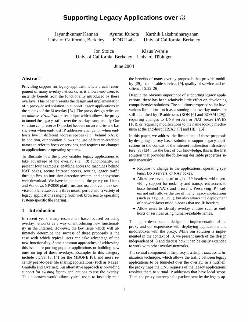
Figure 2:(a) Two native applications communicating over an over-lay network. (b) A RON-like Solution (c) Address-virtualizationbased solution
3.1 Emulating a Native Client
The basic idea behind interfacing a legacy application to anoverlay is to emulate a native client. Consider a general over-lay network where end-points are identified by unique over-lay identifiers. An overlay ID can be an IP address [6], aDNS-like name, a source route [7, 21], ani3 ID [24], or anyunique string of bits. While in general, an overlay ID canbe associated with a service or a connection, for simplicity,in this section, we assume that IDs are associated only tohosts. In the remainder of this section, we use this overlaynetwork model to motivate and present the address virtual-ization technique.
Figure 2(a) shows a native application2 NA running on hostA that sends packets to another native applicationNB onhost B. The packets sent byNA are destined toidB, theidentifier of the end-host running applicationNB. Let us re-place native applicationNA with a legacy applicationLA.SinceLA is oblivious to the existence of the overlay net-work, it knows nothing about the overlay ID ofNB. A tradi-tional technique to address this problem is to use a proxy tointercept the IP packets sent by legacy applications, and for-ward them toidB (see Figure 2(b)). An example of overlaynetwork that employs this technique is RON [6].
However, in a general overlay network that supports mobilityor enables the access of hosts behind NATs, the legacy ap-plications cannot use the IP address of the remote host. Oursolution to this problem is to use avirtual addressto iden-tify the other end host. A virtual address has local scope onlyand it is used by the proxy to intercept the legacy applicationpackets and forward them to the corresponding overlay ID.
The final piece of our solution is to leverage the DNS lookupmechanism to hand over virtual addresses to applications. Inparticular, the proxy intercepts the DNS request of an appli-cation (locally) and resolves it to a virtual address and an
2A native application directly talks to the overlay network. Fore.g.,it sends and receives packets using the overlay packet format.
3

overlay ID. Figure 2(c) illustrates this process. LetnameB
be the name of the end-host runningNB. The proxy inter-cepts the DNS request ofLA for nameB and resolves it to avirtual addressIPX which has local scope only.
Note thatIPX need not have any relationship with the ad-dress ofB, and thus need not change when the address ofB changes. This allowsA and B to live in different ad-dress spaces (e.g.,A can be on an IPv4 network, whileBcan be on an IPv6 network) or/and be mobile. For now, as-sume that the proxy knowsidB, the overlay identifier of themachine namednameB. The proxy then stores the map-ping IPX→idB, and returnsIPX as the DNS reply toLA.The legacy application sends the subsequent packets to ad-dressIPX , which are encapsulated and sent over the over-lay. Packets in the other direction are sent toidA and arereceived by the proxy over the overlay. The proxy decapsu-lates these packets, rewrites the source address toIPX anddelivers them to the application. Thus, to the legacy appli-cation, the proxy emulates a remote host with addressIPX .We refer to this technique asaddress virtualization.
Intuitively, we can imagine that the proxy captures pack-ets that the legacy applications send/receive by faking avirtual interface. Addresses for both the virtual interfaceand for emulating the remote host can be allocated froma pool of reserved IP addresses (such as10.0.0.0/8). Atthe sender, whenever a new DNS request is intercepted, theproxy chooses a free address randomly from this pool.
Using DNS-like names to intercept legacy traffic has twomain advantages: convenience and flexibility. Firstly, usersof the application can use human-friendly DNS-like namesas they are used to. Secondly, this approach allows users toindependently define a new namespace specific to an overlay.Application preferences can be encoded in the name used,thus allowing users to decide a policy at “run-time”. Thiswould be useful if the proxy is used with multiple overlayssimultaneously; the packets can be routed over a particularoverlay based on the name suffix.
In the next few sections, we address the following questions:(a) how is an overlay DNS name resolved to an overlay iden-tifier? and (b) how can we preserve the original IP headerswithout re-writing addresses?
3.2 Resolving Names
We now describes how the proxy resolves a name to an over-lay identifier. These names need not belong to a registeredDNS namespace, since resolution of these names is usuallydone by a proxy and not a legacy DNS server. For clarity,we refer to names that are not resolved using DNS as over-lay DNS names. In our implementation, we use names witha suffix .i3 to refer toi3 DNS names. We consider threedesign alternatives for resolving an overlay DNS name to anoverlay ID.
L A
Proxy
IP PA
IP A
IP VB IP PA data
IP VB IP PA dataid BIP F IP A
IP PB IP VA data
IP VB id B
id A IP VB
IP F
L B
Proxy
IP PB
IP B
IP VA id A
id B IP VA
IP L
IP VB IP PA dataid BIP B IP L
Host A Host B
dst src ID dst src
encapsulationIP header
originalIP header
dst dst srcsrc
Figure 3:The headers of a packet forwarded fromLA to LB .Packet headers contain destination address followed by source ad-dress.
• Global Resolution.Use a modified DNS or a DHT suchas OpenHash [11] to store the mapping between overlayDNS names and overlay IDs.
• Local Resolution, Global Scope.Use an implicitmethod such as applying a well-known hash functionon the name to obtain the ID.
• Local Resolution, Local Scope.Use a local addressbook to explicitly store the name-to-ID mappings.
Global resolution provides a convenient way for users tomanage names. However, this level of names would be aspace of conflict much like DNS names are (as argued bySFR [27]). In addition, a global resolution scheme usuallyrequires a central authority and a separate infrastructure tostore the mapping.
Local resolution of names with global scope also has theconvenience of global resolution without requiring an infras-tructure. However, it also has the problem of name conflicts,apart from being susceptible to impersonation and other se-curity attacks described in [3].
On the other hand, explicit storage of name-to-ID mappingsin a local address book provides better security. An addressbook is similar to a phone book where person names are re-placed by overlay names and phone numbers by overlay IDs.Also, like the names in a phone book, the names in the ad-dress book have only local scope. The downside of using ad-dress books is that they are not easy to maintain and operatewith.
In fact, the tradeoffs between decentralized operation, secu-rity, and human-friendliness in the name-to-ID mapping thatwe see here have been articulated before in [3]. In our imple-mentation, we use the local resolution mechanism using anaddress book, as we place greater emphasis on security.
3.3 Preserving IP Headers
In our solution, the proxy emulates a remote host to the lo-cal legacy application by returning a virtual address. With a
4

random choice of virtual addresses at the proxy at both endhosts, source address re-writing is necessary, even if both thesender and receiver live in the same address space.
There are two reasons to avoid IP header rewriting. First,it allows us to support popular applications (e.g.,ftp andH.323 ) that encode addresses in the packet payload. Sec-ond, it allows us to deploy network layer middle-boxes, suchas intrusion detection systems, on the overlay data path. Wedescribe such an application in Section 6.4.1.
In this section, we present a simple solution that avoidsrewriting IP headers. The main idea behind our solution isto assign virtual interface addresses to the proxies in sucha way that the need for address re-writing is obviated. Tounderstand our solution better, consider the example in Fig-ure 3 that shows the headers of a packet as it is forwardedfrom LA to LB. The crucial point to note is that proxy athostA is configured to fake a virtual interface with addressIPPA that is different from the host’s Internet-routable ad-dressIPA. From the point of view of a legacy application,this is equivalent to a host with two interfaces:IPPA andIPA. In order to intercept the packets of the legacy applica-tions, hostA is configured such that all legacy applicationssend and receive packets on interfaceIPPA. As a result, thesource address of an IP packet sent byLA is IPPA. The des-tination address of the packet isIPV B, which represents thevirtual address returned by the proxy toLA in response to itsDNS request. Similarly, the source and destination addressesof the packet received byLB areIPV A andIPPB .
Hence, the only way to avoid address rewriting is to letIPPB = IPV B and IPV A = IPPA. While these con-straints can be enforced by exchanging the virtual interfaceaddresses during the control protocol, our implementationavoids the overhead of an additional round-trip by choos-ing the virtual interface address of the proxy as a hash ofits public ID. In our example, we haveIPPB = IPV B =10.H(idB) andIPV A = IPPA = 10.H(idA), whereH()is a well-known hash function that maps256 bit IDs to 24bits.
In our implementation, we use an address block of size224 toallocate the virtual addresses, and so the probability of colli-sion is not negligible. In case of collision, the proxy revertsto choosing an available virtual address at random. In suchcases, we no longer preserve the IP header of the packets,but would continue to support the vast majority of legacy ap-plications which do not need this requirement. We note thatthis technique assumes that applications do not specificallybind to a particular interface but can receive packets sent toany interface on the host (e.g.,by the use ofINADDRANY).This assumption holds in practice as most applications sup-port multiple interfaces anyway.
L A
Proxy
IP VB ÿid B
(IP A , id A )
(dst=IP VB , src=IP A ) L B
Proxy
IP VA ÿid A
(dst=IP B , src=IP VA )
(dst=id B , src=id A )
i3
L A
Proxy
IP VB � id BA
id AB IP VB
(dst=IP VB , src=IP A ) L B
Proxy
IP VA � id AB
id BA � IP VA
(dst=IP B , src=IP VA )
(dst=id BA )
i3
id AB id BA
(a)
(b)
Host A (IP B , id B )Host B
(IP A )Host A (IP B )Host B
Figure 4:Two design choices for thei3 proxy. (a) Per-host Identi-fiers (b) Each host maintains an ID for every other host it commu-nicate with.
4 Realization in i3
In this section, we present the realization of the address vir-tualization technique ini3. We start with a simple scenario inwhich both the proxy and the legacy applications run on thesame machine. We remove this assumption in Section 4.4.
We now describe the three main aspects of thei3 proxy de-sign in detail: howi3 identifiers are mapped to underlyingconnections, how packets are tunneled overi3 (data plane),and how this mapping state is installed (control plane).
4.1 Identifier Allocation
In the description of the general proxy, IDs were associatedwith hosts. Ini3, this would mean that each host would main-tain only one trigger ini3, and eachi3 encapsulated packetcarries both the destination and the source IDs. An alternaterealization of ID mapping thati3 allows is using the notionof public and private triggers (refer Section 2).
Figure 4 illustrates these two possible realizations when alegacy applicationLA running on hostA contacts applica-tion LB running on hostB. In the first scenario, proxies atA andB maintain only one ID each,idA and idB respec-tively. In the second scenario, in addition to the ID used forinitial communication (public IDs), hosts maintain a sepa-rate private trigger for every end-host it communicates with.HostsA andB maintain IDsidAB andidBA for communi-cating with each other, along with the mappings required toperform overlay↔IP translations.
Using private triggers has the following two advantages.First, in the case ofi3, an end-host can protect itself againstDoS attacks by just removing the private trigger correspond-ing to the malicious host [12]. Hence, all the the packets fromthe malicious host will be dropped ini3. Second, the fact thatan overlay packet does not need to contain a source ID trans-lates to a non-trivial saving of32 bytes per packet. However,the downside of the second realization is that the number of
5

(a)
A
B
C
D
id AB A
id AC A
id AD A
(d s t= id AB )
(dst=id AC )
(dst=id AD )
A
B
C
D
id A* A
(d s t= id AB )
(dst=id AC )
(dst=id AD )
(b)
Figure 5: (a) Host A maintains a trigger intoi3 for every hostit communicate with. (b) Host A maintains a single trigger with aprefix shared by IDsidAB, idAC , andidAD .
triggers the end-host needs to maintain ini3 can be quitelarge. We now discuss how we use the anycast primitive ini3 to achieve the best of both these realizations.
Efficient State Maintenance.At one extreme, a proxyAcan choose the IDs of all its triggers such that they share thesame prefixp, and then insert only one trigger with prefixpin the infrastructure (see Figure 5). Since packets forwardedby i3 to the end-hosts contain the IDs that they were sent to,the proxy can determine which connection the packet wassent to.
While this approach does not undermine any host-specificpolicies that can be implemented purely at the end-hosts,this anycast optimization would prevent the proxy from ex-ercising DoS protection features ofi3 [12]. If anycast is em-ployed, an end-host can stop a DoS attack only by droppingthe shared trigger, which, in this case, would sever all ex-isting connections. An end-host can strike a middle groundby associating distinct triggers to the more important con-nections, and triggers with shared IDs to the less importantones.
4.2 Data Plane: Packet Tunneling
As shown in Figure 4(b), the proxies need to maintan thefollowing mappings to perform packet tunneling: (a) localvirtual address to remote private and public triggers, and (b)local private trigger to local virtual address.
Packets sent by local applications destined to local virtualaddresses are encapsulated and sent to the remote privateID. Packets received on the local private ID are decapsu-lated, and sent to the application after the source address isre-written. For instance, in Figure 4(b), the proxy atA usesthe mappingIPV B→idBA to tunnel packets sent byLA toB, and the mappingidAB→IPV B to re-write the source ad-dress of the packets fromB.
A proxy can reduce the latency on the data path by choos-ing its private IDs to reside on nearbyi3 nodes. One suchmechanism is described in [24]: the basic idea is for eachproxy to independently sample the ID space and determinethe latency to a particular ID. This mechanism can be imple-mented without knowledge of all thei3 servers and the IDseach server is responsible for.
DNS queryfor name B get id B
allocate IP VB
allocate id AB trigger insert
trigger ack
IP VB id BA
DNS reply,IP VB
id AB A
(dst=IP VB ,..) encapsulate id B B decapsulate
(dst=id B ,src=id AB ,�)
allocate IP VA
allocate id BAtrigger insert
trigger ackid BA B
IP VA id AB
id BA IP VA (src=IP VA ,..)
L A Client Proxy Server Proxy L Bi3
Time
(dst=IP VA ,..)encapsulate(dst=id AB ,src=id BA ,�)
via trigger [id AB |A]decapsulate(src=IP VB ,..)
IP VB id B, id AB
id AB IP VB
1
2
3
Figure 6:The time diagram of setting up the state at proxies run-ning on hostsA andB in Figure 4(b).
4.3 Control Plane: Installing Mapping State
In this section, we present a protocol for installing the map-ping state at proxies. We use the termsclient proxy andserver proxyto refer to the proxy when it performs the opera-tions invoked at the initiator (e.g.,ssh client) and target (e.g.,ssh server) of a connection respectively. This separation isuseful while describing the different proxy instantiations inSection 4.4.
Figure 6 shows the time diagram of the protocol when clientLA initiates a connection to serverLB. We assume that hostB maintains a trigger with a well-known ID (idB) at whichhostA can initiate the connection. In addition, hostA insertstrigger [idAB|A] to receive packets fromB, and hostB in-serts trigger[idBA|B] to receive packets fromA. Using theterminology in [24], we refer to[idB|B] as the public triggerof B, and to[idAB|A] and[idBA|B] as private triggers. Themain component of the protocol is how proxies exchange theprivate identifiersidAB andidBA.
As shown in Figure 6, the protocol can be divided in threesteps: (1) the client proxy resolves the DNS request, insertsa private trigger for the server, and starts installing the map-ping state; (2) the server proxy installs the mapping state,and inserts a private trigger for the client; (3) the client proxycompletes the installation of the mapping state. We describethe details of the protocol next.
In step1, the client proxy atA intercepts the DNS requestof LA for nameB, and resolves it to the identifier of thepublic trigger inserted by hostB, idB. The proxy allocatesa virtual IP addressIPV B that is used to impersonate hostB, inserts a private trigger[idAB|A] (to be used by the re-mote hostB to send packets toA) in i3, and stores themappingsIPV B→idB andidAB→IPV B. At this point, theclient proxy returnsIPV B as the DNS reply toLA.
In step2, client LA sends packets using the addressIPV B
which the client proxy intercepts and, using the mapping it
6

stores, encapsulates as ani3 packet destined toidB. Theclient proxy piggybacks the private IDidAB specific to hostB along with this packet.
When the server proxy atB receives the packet, it decapsu-lates the packet and performs a procedure similar to the clientproxy. In particular, the server proxy allocates a virtual ad-dress,IPV A to impersonate hostA, inserts private trigger[idBA|B] to receive packets from hostA and stores map-pings idBA→IPV A and IPV A→idAB. The server proxyrewrites the source address of the IP packet toIPV A beforesending it toLB.
In step3, when the data packet is sent fromB toA, the serverproxy piggybacks its private IDidBA to the client proxy.As an optimization, instead of waiting for a data packet, theserver proxy can send a control packet toLA with its privateID. On receiving this private ID, the client proxy updates itsmapping toIPV B→idB, idBA.
This protocol is both efficient and robust. Since the privatetriggers are inserted at nearby servers, the additional delaywhen opening a connection to a new machine is minimal.We can avoid the delay of trigger insertion by using the any-cast optimization discussed in Section 4.1. Furthermore, sub-sequent connections to the same machine simply re-use themapping state and the private triggers.
The protocol is robust in the presence of packet losses. If ei-ther the first packet fromA to B or the first packet fromB toA is lost, the client proxy will simply continue to piggybackthe private IDidAB in the subsequent packets sent byLA
and forward these packets toB via its public identifieridB.Once the client proxy obtains the private identifieridBA, itsends packets toidBA.
4.4 Deployment Alternatives: Remote Proxies
The basici3 proxy presented in Section 4 assumes that bothends of the communication run the proxy. However, thereare practical scenarios wherei3-enabled hosts might wish tocontact (or be contacted by) hosts that do not runi3 proxy.For example,i3-enabled clients may still want to contactpublic servers such ascnn.com to take advantage of mo-bility or service composition. In another example, an orga-nization might wish to run one proxy for all its machinesinstead of installing ani3 proxy on each of them. To supportthese scenarios, we have developed ani3-to-IP proxy, whichacts as a proxy for a set of hosts that are noti3-enabled. Werefer to such hosts as legacy hosts.
4.4.1 i3-to-IP Proxy
In this section, we consider ani3-to-IP proxy deployed tofacilitate ani3-enabled client to communicate with a legacyserver overi3. Since the functionality of this proxy is verysimilar to that of the server proxy, we present only the differ-ences from the server proxy here (see Figure 7).
L A
Proxy
IP VB id BA
id AB IP VB
(dst=IP VB , src=IP A ) L B
Proxy
IP P :P P id AB
id BA IP P :P P
IP P :P P IP B
(dst=id BA )
i3
id AB id BA
(IP A )Host A (IP P )Proxy P (IP B )Host B
(dst=id AB )(dst=IP A ,src=IP VB )
(dst=IP P :P P , src=IP B )
(dst=IP B , src=IP P :P P )
Figure 7:A remote proxy for legacy applicationLB .
Consider ani3-to-IP proxyP that acts on the behalf of aset of legacy hostsHp, and letidP be the public identifierof P . An i3-enabled client that wishes to contact a legacyserverB from the setHp sends the DNS name of the legacyserver along with its own private trigger toidP . WhenPreceives the DNS request it resolves the request, inserts aprivate triggeridBA to set up its end of thei3 connection,and sendsidBA to the client.
In addition, thei3-to-IP proxy plays the role of a NAT boxfor the set of serversHP . Thei3-to-IP proxy allocates a portnumberPP that is used, together with its addressIPP , to im-personate hostA to hostB. In particular, thei3-to-IP proxyforwards the packets from hostA to B using the source ad-dress and port number(IPP :PP ), and it forwards the packetsreceived at(IPP :PP ) to hostA using IDidAB.
We allow users to specify routing policies for a legacy DNSname, which indicates whether packets to that host should besent directly over IP or through ani3-to-IP proxy (identifiedby its public trigger).
4.4.2 IP-to-i3 Proxy
In this section, we consider the case where the client doesnot run a proxy. Instead this functionality is implemented bya special proxy, called IP-to-i3 proxy, that sits between theclient and either ani3-enabled server or ani3-to-IP proxy.The functionality of IP-to-i3 proxy is almost identical to theclient proxy. The key differences between the client proxyand the IP-to-i3 proxy are that the DNS request sent out bythe legacy client has to reach a valid name server which theproxy should have control over, and that the address that thename server returns has to be a real Internet-routable address.
Our solution is very similar to the scheme implemented inAVES to offer transparent connectivity to machines behindNATs [16]. As a result, our solution shares the same fun-damental limitations with AVES. Since DNS queries can berecursive, the proxy (acting as the name server) is not guar-anteed to know the IP address of the legacy client that madethe DNS request. Hence, it has to use a heuristic to correlatea DNS request and the first data packet. We discuss how wepartially address this issue in Appendix 11.
4.5 Tradeoffs in Functionality
Our solutions for the three deployment scenarios involvetradeoff between several factors that we outline in Table 1.
7

Table 1: Deployment Scenario Vs Properties
i3 proxy i3-to-IP proxy IP-to-i3 proxy
Access Required End-host End-host DNS serverAdditional Infrastructure Required None Dedicated Machine Waypoint Machines
Preserving IP headers Yes No NoMobility Yes Limited (Only Client) Limited (Only Server)
NATed Hosts Supported Yes Limited (Only Client) Limited (Only Server)Name Resolution Local Resolution Remote DNS Resolution Allocation Authority
Firstly, while the remote proxies provide an alternative whenrunning the basici3 proxy on the end-host is not possi-ble, they are limited in their support for mobility, NAT andpreservation of IP headers. Secondly, the IP-to-i3 proxy alsorequires control over a DNS server for a domain name, andin general, the remote proxies need dedicated machines torun on. Finally, the name resolution scheme also differs inthese deployment scenarios: ani3-to-IP proxy resolves aDNS name on the behalf ofi3-enabled hosts and an IP-to-i3 proxy uses its private address book to resolvei3 names.This implies that the IP-to-i3 proxy has to manage allocationof thei3 DNS namespace seen by legacy IP clients.
5 i3 Revisited
Deploying real applications with the proxy has helped usidentify certain functionalities desired by users. While someof these functionalities (such as connecting to legacy serversthroughi3) can be handled by proxy and purely at end-hosts,others require modification to the infrastructure/overlay. Inthis section, we discuss two such issues and discuss how weaddress them. First, while the very large ID space ofi3 al-lows us to uniquely identify every computer and device inthe world, the standardi3 implementation does not allowone to access machines behind NATs or firewalls. Second,some users were concerned about the fact that every packetwas relayed through at least onei3 node; they wanted theflexibility of circumventingi3 for the data path.
5.1 Accommodating NAT Boxes
In this section, we present a simple modification toi3 in or-der to accommodate end-hosts behind NATs. The modifica-tion happens only on the control plane; data forwarding isunmodified. The main idea is to rely on the control planeprotocol initiated by the host for inserting triggers ini3. Dur-ing trigger insertion, the NAT allocates a globally routableaddress through which external hosts can contact the NATedhost. Our solution ensures that other hosts only use this NAT-allocated address to contact the host behind the NAT. Thissolution requires no changes or configuration of the NAT boxas trigger insertion is initiated by the end-host.
Figure 8 illustrates our solution. LetIPA be the (locallyvalid) IP address of a host behind a NAT, and letPproxy bethe port number of the proxy. Assume the proxy inserts a
L A
Proxy
Host A (IP A )NAT (IP N )
dst=IP F :..src=IP A :P proxytrigger=[id A |IP A :P proxy ]retaddr=IP A :P proxy� id A IP N :P N
dst=IP F :..src= IP N :P Ntrigger=[id A |IP A :P proxy ]retaddr=IP A :P proxy�
dst=�src=IP F :...trigger=[id A |IP N :P N ]retaddr= IP N :P N�
IP F
IP T
Figure 8:Supporting NATs ini3.
trigger [idA|IPA:Pproxy]. The fieldsdst andsrc representsthe IP destination and source addresses of the packet, andthe fieldretaddrrepresents the address of the proxy that hasgenerated the message. Note that thedst field is set to theaddress of ani3 node known by the end-host (IPF , in thiscase). This node is not necessarily the node where the triggeris ultimately inserted. Upon receiving the trigger insertionpacket, the NAT box translates the source address and portnumber of the packet,IPA:Pproxy, to IPN :PN whereIPN
is the IP address of the NAT box, andPN represents the portnumber used by the NAT box to identifyIPA:Pproxy.
When the packet arrives at the firsti3 node,IPF , the nodechecks whether the packet’sdst and retaddr fields are thesame. If not, the node concludes that the packet has traverseda NAT and overwritesretaddr with the packet’s source ad-dress. This enables cache messages to be sent to the NAT. Inaddition, if the trigger points to an IP address (which is thecase in this example), thei3 node also overwrites the secondfield of the trigger. If the trigger points to another ID, thei3node does not modify the trigger. The packet is then routedto thei3 nodeIPT that is responsible foridA. Upon receiv-ing the packet, nodeIPT inserts, challenges, or refreshes thetrigger. Thus, the control plane protocol ensures that triggerspoint to only globally valid IP addresses. This allows the dataforwarding to work seamlessly.
The protocol we have described however cannot support cer-tain types of restrictive NATs [20] such as restricted coneNATs and symmetric NATs which allocate address and fil-ter packets based on source and destination addresses. In ourexample, this means thatIPT cannot send packets using theaddressIPN :PN , since this address is allocated only for thesource-destination pair(IPA, IPF ). To get around this prob-lem, we force the proxy to contactIPT directly during trig-
8
ger insertion, so that an address is allocated by the NAT forthei3 serverIPT .
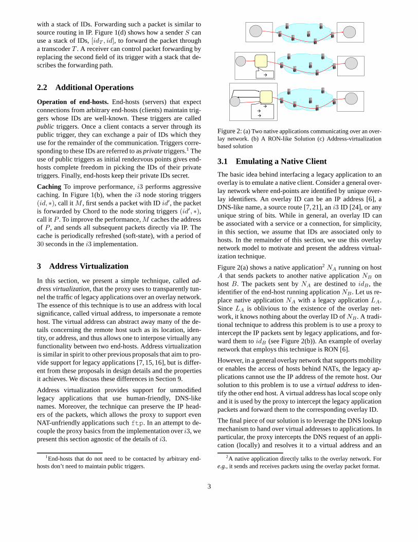
5.2 Shortcuts
In the originali3 design, every packet is relayed through atleast onei3 node. While this indirection is necessary for use-ful functionalities such as mobility, anonymity, and access tomachines behind NATs, it is, in general, less efficient than di-rect IP communication. To alleviate the efficiency problem,we propose a straightforward modification toi3: we allowthe communication path between an sender and receiver tocircumventi3. We refer to this technique asshortcut. Short-cuts are used only if both the sender and the receiver allowits use. Shortcuts apply only to triggers of the form(id, R)whereR is the IP address of the receiver and the sender sendspackets addressed toid.
The shortcut technique allows the sender and the receiverto express their preference for using shortcut in the dataand trigger insertion packets respectively. Consider a hostAsending a data packet to IDidBA. When the packet reachesthei3 node storing trigger[idBA|B], if either the data packetor the trigger do not have the shortcut preference set, thei3 node sends a cache reply message toA and forwardsthe message toB. Otherwise, thei3 node just forwards thepacket to hostB, and lets the proxy on hostB reply with acache message toA. After receiving the cache message fromB, proxy A sends all subsequenti3 packets directly to theproxyB.
Note that this protocol does not work if the sender and thereceiver are behind NATs (of the restricted cone or sym-metric kind). This implies that shortcuts should not be usedby a a NATed host for sending data or inserting triggers.An end-host might also avoid using shortcuts to preserve itsanonymity or to maintain connectivity under mobility.
With shortcuts, the role ofi3 reduces from a routing infras-tructure to a lookup infrastructure. The natural question thatfollows is: why would an end-host that prefers shortcuts usei3 instead of sending packets directly via IP? For some appli-cations,i3 provides a better lookup infrastructure than DNSin that it allows end-hosts to quickly update their triggers. Inthe above example,A′s proxy maintains the cache entry ofBby soft state. This implies that ifB moves during the courseof the communication, once the cache entry times out,A′sproxy would revert to sending packets addressed toidBA toi3, and eventually to the new location ofB.
6 Applications
In this section, we discuss four application scenarios sup-ported by thei3 proxy that we have experience with: en-abling access to home machines behind NATs, secure In-tranet access, anonymization, and middle-box applications(e.g.,intrusion detection).
6.1 Accessing Machines Behind NATs
Users today use ad-hoc mechanisms to access their homemachines behind NATs. This problem can be solved by astraightforward use ofi3 proxy: the home machine runs ai3 proxy and the user can usei3 to contact his machinefrom elsewhere. This solution requires no changes or re-configuration of the NAT box.
6.2 Secure Intranet Access
For security reasons, organizations typically would like toprovide restricted access for connections into their Intranetfrom outside. To this end, VPN-based (Virtual Private Net-works) solutions are currently used in conjunction with fire-walls (for more information on VPNs, refer to [1]). We nowdescribe howi3-to-IP proxy can be used as an alternative forsecure Intranet access, and discuss the potential advantagesover VPNs.
In this scenario, thei3-to-IP proxy runs inside the organiza-tion and hence has unrestricted access to all the intranet ma-chines. External end-hosts relay through thei3-to-IP proxyin order to access Intranet machines. Authentication of exter-nal end-hosts is a fundamental requirement in this scenarioand to this end, we added an authentication wrapper over thei3-to-IP proxy.
Our authentication mechanism for thei3-to-IP proxy isbased on a simple RSA public-key based protocol similarto ssh . We assume that there is some out-of-band mech-anism for thei3-to-IP proxy and a legitimate client proxyto exchange their public keys (e.g.,smart cards). Our au-thentication protocol is a simple challenge-response protocol(which incurs two additional round trips). Only if the authen-tication mechanism is successful, the client proxy obtains aprivate trigger through which it can contact the thei3-to-IP proxy. Communication from this point onwards proceedsjust as before. Unlikessh which encrypts all data packetsusing session keys negotiated in the authentication phase, wedo not perform any encryption operation on the data path toavoid additional overheads. Resistance against a man-in-the-middle adversary who hijacks an authenticated connectioncan be obtained by application-level end-to-end encryption.
Our i3 based solution has two advantages over VPN-basedsolutions:
• Multiple intranets:Using ani3-to-IP proxy, a client canaccess multiple intranets at the same time. In contrast,existing VPN solutions do not usually support this fea-ture. If both the intranets use the same address range,then connecting to both intranets can be impossible.
• Security:Since a VPN client gets a virtual interface ad-dress on the organization’s network, an infected clientcan potentially infect internal machines to which theclient has unrestricted access to. Such an infection ishard to perform in our case. This is because an infected
9

id M
id AB
id BA
id M , id BA data
id AB data
id BA data
id M , id AB dataclient A
server B
i3
middle-box
Figure 9:Example of using a middle-box with IDidM . The privateIDs of the end-hosts areidAB , andidBA, respectively.
client cannot access any Intranet host directly using itsreal IP address. Moreover, only the addresses in the vir-tual address range that have been allocated by the proxyfor ongoing connections are vulnerable.
6.3 Anonymization
In the current Internet, an end-host who wishes to con-tact other end-hosts anonymously relays its traffic througha trusted third party. Examples of such schemes include re-mailers that relay email anonymously [10] and web surfinganonymizers [4]. This mechanism is naturally emulated byan i3 proxy that relays its traffic throughi3 (without usingshortcuts), as such a proxy reveals only its private triggers tothe server proxy. This solution assumes that thei3 infrastruc-ture is trusted. One way of strengthening the anonymity guar-antee is to choose a randomi3 server as a relay rather thanthe closesti3 server. The performance experienced by theuser is determined by his latency to thei3 server he choosesto relay through: clearly, choosing a randomi3 server in-curs an additional performance penalty. In fact, the user cantrade between the level of anonymity and performance. Notethat preserving IP headers according to the address alloca-tion mechanism in Section 3.3 leaks information about theidentity of the client: a server can identify other requestsinitiated by the same client by using the virtual address ex-changed during private trigger exchange. If the client desiresanonymity, it can either periodically change the virtual ad-dress assigned to its applications (which affects ongoing ses-sions) or simply allow its IP headers to be modified. Notethat our approach also assumes that application-level identi-fying data (e.g.,cookie data) is removed at the client proxyitself.
6.4 Middle-box Applications
We now discuss a more general class of applications enabledby the i3 proxy. Several useful functionalities such as In-trusion Detection ( [18]), QoS ( [26]) can be conceptuallyviewed as being achieved by imposing a middle-box on thedata path. We describe how such a middle-box can be ac-commodated by thei3 proxy.
i3’s primitive of stack of IDs enables thei3 proxy to supportmiddle-boxes in a seamless fashion. First, we describe howa client proxy can impose a middle-box on its path and thendescribe how a server proxy can do the same. Ani3 clientproxyA that wishes to communicate with anotheri3 server
proxyB through a middle-boxM addresses its data packetsto the stack[idM , idBA] whereidM is the public trigger ofM , andidBA is the private trigger ofB (see Figure 9). Dur-ing control plane negotiations,A also informsB that packetssent toA should be addressed to the stack[idM , idAB]. Thisprotocol ensures that data packets are sent in both directionsthrough the middle-box. Ani3 server proxy that wishes allusers contact it through a middle-box can use a similar pro-tocol to achieve the same. Note that this solution allowsBto address its packets directly toidAB and thus subvert themiddle-box: this can be prevented by some protocol betweenthe client proxy and the middle-box (e.g., the middle-boxmarks packets in a special fashion). Our solution also allowsthe middle-box to authenticate client proxies, if it desires todo so.
This proxy-based solution has several advantages over cur-rently used solutions. Today, setting up a data path througha middle-box is typically done either in an end-host oblivi-ous fashion, or by application-specific configuration such asusing HTTP proxies. The first alternative requires that themiddle-box be placed at specific topological locations (e.g.,behind the access link of a network) over which end-hoststypically have no direct control. The second alternative re-quires users to configure every application of interest. In con-trast, our proxy-based solution allows any arbitrary host toserve as a middle-box and does not require any application-specific configuration. Furthermore, our solution can usei3anycast to distribute the middle-box functionality over sev-eral machines.
6.4.1 Intrusion Detection
As a proof of concept, we have implemented an intrusiondetection system that can be used by anyi3 enabled client.Our system is based on Bro [18], a well-known intrusiondetection software. This example illustrates not only howlegacy applications can use the middle-box functionality, butalso how the middle-box functionality can be realized usinglegacy software. Our implementation involves ani3-specificshim layer that runs on the same machine as Bro. This shimlayer acts as ani3 middle-box in order to capture packets sentbetweeni3 proxies and rewrites such packets with virtualsource and destination address to emulate an conversationbetween two virtual hosts. Note that no rewriting is requiredif the source and destination preserve IP headers, in whichcase, the middle-box uses the virtual addresses exchangedduring trigger negotiation. Bro captures these rewritten pack-ets and performs analysis in order to identify potential at-tacks. We assume that end-hosts are informed of these at-tacks in some out-of-band fashione.g.,by sending alerts to atrigger specified by the end-host.
An useful type of analysis performed by Bro is stateful anal-ysis which maintains per-flow state while analyzing packets,e.g.,reconstructing TCP sessions in order to detect certain at-
10

Figure 10:Analysis performed by Bro
tack signatures. This requires the shim layer to re-write the IPheaders of all packets belonging to a given session with thesame source and destination IP addresses. Thus, thei3 shimlayer needs to maintain state for each source-destination pair.In order to install this state, we also relay the control mes-sages that negotiate the private triggers between the end-hostproxies through the middle-box using ID stacks.
We deployed Bro on a FreeBSD machine in Berkeley alongwith the i3 shim layer, through which users can route theirtraffic by configuring their proxies. We discuss two examplesof possible uses to illustrate the flexibility of our implemen-tation. Figure 10 illustrates a ftp analysis performed by Broon the traffic to a server proxy running a ftp server that im-poses the middle-box on the path. This ftp analysis identifiesan attempt bybadguy to upload a file calledeggdrop , thename of a well known backdoor. Another example illustratedin the figure is a http analysis of the traffic of a client proxybrowsingwww.nytimes.com through two middle-boxes:the Bro middle-box andi3-to-IP proxy. The http analyzerin Bro identifies the multiple connections initiated by thebrowser and the GET requests in each of these connections.Also note that in the first example, the proxies preserve theIP addresses (10.1.244.127, 10.2.51.9) and thus reveal theiridentity to the middle-box. In the second example, the prox-ies contact the middle-box anonymously, and the middle-boxassigns its own virtual addresses (10.0.0.1− 10.0.0.4). Thesecond example illustrates the practical necessity of short-cuts: without shortcuts, an additional overhead of4 Internethops would be imposed even for clients that do not desireanonymity.
Our solution has certain fundamental limitations as to thetype of analysis that can be performed by Bro. Due to the factthat an end-host can contact the middle-box anonymously,it is not possible for Bro to correlate information gleanedfrom different communication sessions. Note however thatan user of the Bro-middle box can always choose to revealhis identity to Bro in order to allow such analysis. Even un-der the assumption that the end-host contacts the middle-
box anonymously, our implementation allows most analysismechanisms that are used in currently deployed intrusion de-tection systems such as signature-based attack detection.
7 Implementation
We have implemented thei3 proxy and its variants, thei3-to-IP proxy and IP-to-i3 proxy, in C/C++ in Linux. Ourimplementation is available in source and binary format ati3.cs.berkeley.edu . We first discuss our implemen-tation of the address virtualization and tunneling techniquesthat apply to alli3 proxy variants. Then, we give details ofour implementation of thei3 proxy and thei3-to-IP proxy(for details about the IP-to-i3 proxy, refer to Appendix 11).
7.1 TUN Based Address Virtualization
The address virtualization technique usestun [2,28], a soft-ware network loopback interface, to capture packets sent bylocal applications. Thetun interface allows user-level pro-grams to capture packets from kernel space.iptables androute [28] are used to redirect DNS packets and pack-ets sent to virtual address respectively to thetun interface.Thus, a legacy application need not be recompiled or linkedwith new libraries. Thetun device also supports packetwrites: packets written on the interface can be sent to the lo-cal application. This feature is used to send the decapsulatedi3 packets to the local application.
There are three limitations of our implementation of the ad-dress virtualization technique. Firstly, the proxies require ad-ministrator privileges to use thetun device. While this isnot a concern for thei3-to-IP proxy and the IP-to-i3 proxywhich will be deployed by few individuals and organizationson dedicated machines, this requirement might be inconve-nient for users who wish to run thei3 proxy. Secondly, theuse of thetun device also implies that only per-host poli-cies can be specified; per-user policies cannot be specified.Thirdly, using thetun device leads to additional overheaddue to copying of packets from kernel to application spaceand vice-versa.
To avoid these limitations, one can implement a dynamic li-brary that can hijack desired system calls. We leave the im-plementation of such a library to future work.
7.2 Tunneling
Tunneling involves two main operations: encapsulation at thesender and decapsulation at the receiver followed by addressrewriting. Packet encapsulation mechanism adds an over-head of37 bytes per packet due toi3 headers. Addition ofsuch headers can lead to fragmentation due to MTU con-straints. An application that wishes to avoid fragmentationcan perform end-to-end MTU discovery. The address rewrit-ing mechanism rewrites the addresses and incrementally up-dates the IP and transport player checksums [13]. We haveimplemented address rewriting for TCP, UDP and ICMP.
11

Note that address rewriting is performed only when whenthe address allocation mechanism described in Section 3.3 isnot possible (e.g.,the virtual address is already allocated).
Maintaining State Consistency.In Section 4.3, we havedescribed how the proxy’s tunneling state is installed; nowwe discuss when this state is removed. Intuitively, the proxyshould maintain the mapping state longer than the legacy ap-plication maintains the virtual address returned by the proxy.The proxy refreshes the mapping state every time one of thefollowing two events occur: a packet is forwarded using themapping state, or a DNS request for that mapping state isinvoked. If none of these events happen, the proxy removesthe mapping state after a predefined interval of timeTO.
We consider two issues when setting the value ofTO: the de-fault TCP keep-alive timer which is7200 sec, and the inter-action with the DNS caching. Despite the fact that the proxyalways returns a DNS reply with a Time-to-Live (TTL) valueof zero, some popular applications (e.g., Internet explorer)ignore the TTL and cache the address. However, in our expe-rience we found that none of the applications we used cachethe DNS reply for more than7200 sec, which is consistentwith the findings reported in [16]. As a result, we chose thedefault value ofTO to be 7200 sec. While this is a largevalue, note that the overhead to maintain the mapping stateis minimal when the proxy uses the anycast optimization. Inthis case, the proxy maintains the mapping state only locally;no trigger is inserted in the infrastructure.
Another scenario in which such incorrect behavior can ariseis if the i3 proxy is restarted during a application session(gracefully or otherwise). The application would continue totry to connect to virtual addresses which the proxy no longerhas state for. To mitigate this problem, thei3 proxy logs itsstate periodically to a file. When the proxy starts up, it canoptionally reconstruct its state by reading in the log from thefile.
7.3 i3 proxy
The i3 proxy is implemented as a multi-threaded applica-tion with two main threads: the packet capture thread andthe overlay interface thread. The packet capture thread readsfrom thetun device to capture application-generated DNSrequests and data packets. The overlay interface threads re-ceives packets from thei3 infrastructure and sends them tolocal applications. Thei3 proxy has been ported to the Win-dows (XP, 2000) under Cygwin usingvtun [2] (a Windowsport of tun ). Thei3 proxy is designed to be highly flexibleand allows configuration through an XML configuration file.The configuration file also allows the user to specify whichlegacy DNS names should be redirected to ani3-to-IP proxy.For ease of configuration, these policies are expressed as asequence of regular expressions for the name, along with apolicy for names that match that regular expression (the pol-icy specifies whether to relay through ani3-to-IP proxy or
directly via IP).
7.4 i3-to-IP proxy
Thei3-to-IP proxy is implemented as two main threads: thei3 interface thread and IP interface thread. Thei3 interfacethread interacts with ani3 proxy in setting up private trig-gers etc, while the IP interface thread maintains the mappingbetween private triggers and ports allocated on behalf of ani3 host. Thei3 interface thread also spawns a DNS helperthread for doing non-blocking DNS lookups: this allows it toscale to multiple users. If the DNS query cannot be resolved,then an error message is returned to the connecting proxy,which then informs the application. The IP interface threadmaintains the private trigger to port mapping in two steps: itstores a private trigger to virtual address mapping, and uses asoftware NAT to maintain the mapping from virtual addressto fake port. We used a Linux software NAT implementationfor thei3-to-IP proxy, which includes packet-rewriting sup-port for several applications (Linux Kernel 2.4.22 has sup-port for FTP, H.323, PPTP, SNMP, TFTP etc.). Thei3-to-IPproxy does not support ICMP since there is no informationin an ICMP packet (such as port numbers) to permit multi-plexing of a single IP address among multiple hosts.
8 Evaluation
In this section, we first present results micro-benchmarkingthe different costs involved in the data and control path ofthe proxy. The benchmarking results indicate that the over-head of using the proxy is minimal, and it can support highdata forwarding rates. We then present wide-area experi-ments that show that, in practical scenarios, using the proxyalong with i3 performs almost as well as underlying IP.These experiments also indicate the performance advantagesof the shortcut option (especially throughput). Even thoughwe have implemented and deployed the applications in Sec-tion 6, we do not present any wide-area benchmarking resultsfor them since the performance does not reflect anything ontheir instantantion ini3 (since the proxy adds minimal over-head, as our microbenchmarking results show).
8.1 Micro-benchmarks
All our micro-benchmarks were conducted on a2.4 GHzPentium IV machine with512 MB RAM running Linux2.4.20. Timing was done usinggettimeofday at the userlevel. We report the timing numbers as a median of at least100 runs (the variation we obtained was minimal).
We used a simple in-house tool that sends data of varioussizes and rates as the legacy client for the proxy. For con-ducting micro-benchmarks, we instrumented the proxy andthe tool reporting the time at pertinent checkpoints.
i3 Proxy: Data Path Overhead.In comparison to a legacyapplication running over the host IP stack, the use of theproxy adds two memory copies of the data: from kernel to
12
the user space and back, for both sending and receiving pack-ets. Figure 11 reports results for the send and receive timesof a single packet of size12003 bytes at the sender and re-ceiver. We split up the total send and receive time into threephases: (a) time taken to move a packet between applicationand proxy, (b) proxy processing overhead, and (c) time takenfor proxy to send/receive a packet.
Total send time per packet= 73
App send to Proxy Proxy processing Proxy send42 (57%) 11 (15%) 20 (28%)
Total recv time per packet= 44
Proxy recv Proxy processing Proxy to App17 (39%) 4 (9%) 23 (52%)
Figure 11:Split-up of per-packet overhead of send and recv withthe proxy. All numbers are in microseconds.
We see that the processing time of the proxy is very little(15% for send and9% for receive) and much of the over-head is for transferring the packet from the application tothe proxy (57% for send and52% for receive). This over-head can be avoided by a dynamic library implementation asmentioned before. The total send time indicates that the rawthroughput that can be sustained is13, 700 packets/second(or 131 Mbps).
i3 Proxy: Lookup Overhead.We first quantify the overheadincurred by the proxy in the control path (i.e., resolution ofnames). We distinguish between two cases when an applica-tion makes a DNS request: either the DNS name has alreadybeen resolved or it is being resolved for the first time. Inthe first case, the proxy immediately returns the name with aminimal processing overhead of15 microseconds. In the sec-ond case, the proxy performs additional operations to setupthe state and hence takes longer (74 microseconds).
8.2 Wide-area Experiments
Over a deployment ofi3 on PlanetLab, we compare thei3proxy to the underlying IP path based on two metrics, round-trip time (RTT) and TCP throughput. In all our experiments,each proxy was configured to use the closesti3 server.
Basic i3 Proxy. We performed experiments with the proxyrunning on three machines at different locations: one eachat Berkeley, UT-Austin and UIUC. The fact that the basici3proxy requires administrator privileges made it difficult forus to procure more machines. We measure RTT with an in-house custom tool that uses UDP packets, and throughputwith ttcp , a popular tool for measuring TCP throughput.
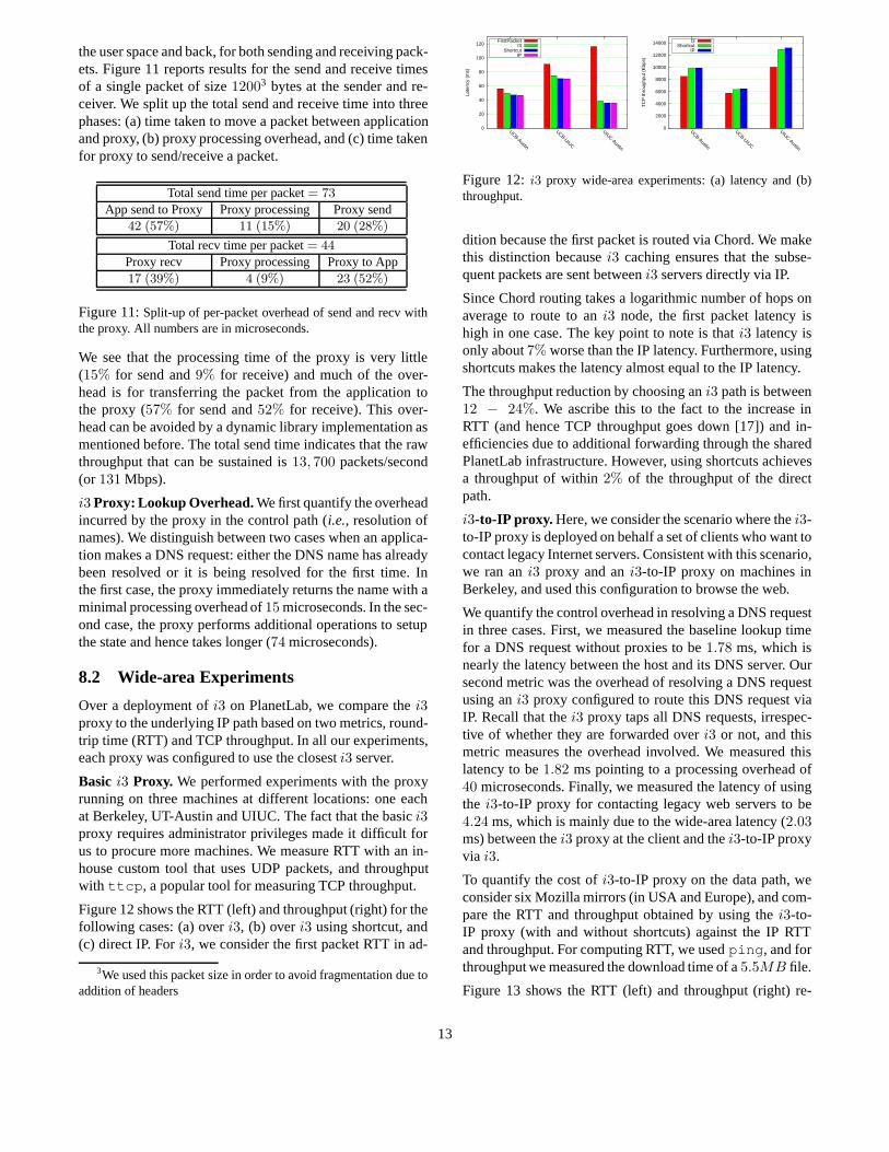
Figure 12 shows the RTT (left) and throughput (right) for thefollowing cases: (a) overi3, (b) overi3 using shortcut, and(c) direct IP. Fori3, we consider the first packet RTT in ad-
3We used this packet size in order to avoid fragmentation due toaddition of headers
0
20
40
60
80
100
120
UCB-Austin
UCB-UIUC
UIUC-Austin
Late
ncy
(ms)
FirstPacketI3
ShortcutIP
0
2000
4000
6000
8000
10000
12000
14000
UCB-Austin
UCB-UIUC
UIUC-Austin
TC
P th
roug
hput
(K
bps)
I3Shortcut
IP
Figure 12:i3 proxy wide-area experiments: (a) latency and (b)throughput.
dition because the first packet is routed via Chord. We makethis distinction becausei3 caching ensures that the subse-quent packets are sent betweeni3 servers directly via IP.
Since Chord routing takes a logarithmic number of hops onaverage to route to ani3 node, the first packet latency ishigh in one case. The key point to note is thati3 latency isonly about7% worse than the IP latency. Furthermore, usingshortcuts makes the latency almost equal to the IP latency.
The throughput reduction by choosing ani3 path is between12 − 24%. We ascribe this to the fact to the increase inRTT (and hence TCP throughput goes down [17]) and in-efficiencies due to additional forwarding through the sharedPlanetLab infrastructure. However, using shortcuts achievesa throughput of within2% of the throughput of the directpath.
i3-to-IP proxy. Here, we consider the scenario where thei3-to-IP proxy is deployed on behalf a set of clients who want tocontact legacy Internet servers. Consistent with this scenario,we ran ani3 proxy and ani3-to-IP proxy on machines inBerkeley, and used this configuration to browse the web.
We quantify the control overhead in resolving a DNS requestin three cases. First, we measured the baseline lookup timefor a DNS request without proxies to be1.78 ms, which isnearly the latency between the host and its DNS server. Oursecond metric was the overhead of resolving a DNS requestusing ani3 proxy configured to route this DNS request viaIP. Recall that thei3 proxy taps all DNS requests, irrespec-tive of whether they are forwarded overi3 or not, and thismetric measures the overhead involved. We measured thislatency to be1.82 ms pointing to a processing overhead of40 microseconds. Finally, we measured the latency of usingthe i3-to-IP proxy for contacting legacy web servers to be4.24 ms, which is mainly due to the wide-area latency (2.03ms) between thei3 proxy at the client and thei3-to-IP proxyvia i3.
To quantify the cost ofi3-to-IP proxy on the data path, weconsider six Mozilla mirrors (in USA and Europe), and com-pare the RTT and throughput obtained by using thei3-to-IP proxy (with and without shortcuts) against the IP RTTand throughput. For computing RTT, we usedping , and forthroughput we measured the download time of a5.5MB file.
Figure 13 shows the RTT (left) and throughput (right) re-
13

0
20
40
60
80
100
120
140
160
CA Georgia
UtahOregon
Indiana
Belgium
Late
ncy
(ms)
I3-LatencyI3-ShortcutIP-Latency
0
2000
4000
6000
8000
10000
12000
14000
CA Gatech
UtahOregon
Indiana
Belgium
TC
P th
roug
hput
(K
bps)
x 10
I3-ThroughputI3-Shortcut
IP-Throughput
Figure 13:i3-to-IP proxy wide-area experiments: (a) latency and(b) throughput. Note that CA mirror’s throughput is scaled down bya factor of 10 to fit the scale.
sults. For RTT, the cost of going through thei3-to-IP proxyis less than2% and drops to0.5% if shortcuts are used. Forthroughput, the penalty wheni3 is used is high if the directthroughput is itself very high; in other cases the penalty wasless than20%. For instance, the raw bandwidth to the CAmirror was about52 Mbps (note that this is scaled down inthe figure to fit the scale) whereas thei3 throughput was26Mbps. However, with shortcuts, the loss in throughput is lessthan5%.
9 Related Work
The problem of providing support for legacy applications hasbeen addressed by many proposals that aimed to introducenew functionality in the Internet either in the form of over-lays, or new network protocols [6, 7, 15, 16, 29]. One differ-ence between these proposals and our solution is that, to thebest of our knowledge, none of these proposals preserve theIP headers in the presence of NATs and mobile hosts. Wediscuss other differences between these proposals and oursnext.
RON [6] uses FreeBSD’s divert sockets to capture packetsfrom local applications in a fashion similar to the way ourproxy uses thetun device. However, RON uses host IP ad-dresses as overlay identifiers, which though suitable for arouting overlay, does not generalize to overlays that sup-port mobility or NATs. ROAM [29] also uses IP addressesas overlay identifiers, but these addresses are different fromthe end-host IP addresses. This allows ROAM, which is builton top ofi3, to provide mobility, but no support for NATs.
TRIAD [7] proposes an implementation called WRAP(Wide-Area Relay Addressing Protocol) that modifies thename lookup mechanism and uses a set of Content Res-olution Routers for resolving the DNS names. HIP [15]also requires the modification of the name lookup mecha-nism at end-hosts and relies on Dynamic DNS enabled withDNSSEC or a set of rendezvous servers. Unlike these so-lutions, our baseline solution4 requires no changes to thelookup protocols.
AVES [16] uses a set of waypoints to stitch together multipleaddress spaces through the Internet. Our IP-to-i3 proxy uses
4The only exception is the IP-to-i3 proxy.
the waypoint approach, but unlike AVES it does not requirethe modification of NAT boxes. Instead, the IP-to-i3 proxyrelies oni3 to access machines behind NATs.
We also share the broader objective of providing new func-tionality to legacy applications with TCP Migrate [23]. How-ever, TCP Migrate [23] modifies the protocol stack, and re-lies on the DNS infrastructure to provide mobility.
10 Discussion
In this section, we address two natural questions: (a) howcan the proxy design be extended to other overlays, (b) whatare the fundamental limitations of the proxy design? We thensummarize our experience with building the proxy and usingit with legacy applications in practical scenarios.
Generalization to Other Overlays.While so far we haveonly implemented and experimented with the proxy in thecontext ofi3, we believe that our design can be easily ex-tended to other overlay networks. Developing the proxy fora new overlay network requires overlay-specific changes tothe following: (a) the mechanism to resolve names to over-lay IDs (see Section 3.2), (2) the control protocol to set upthe mapping state (see Section 4.3), and (3) the data packetencapsulation and decapsulation primitives.
In general, the proxy can be modified to support multipleoverlays simultaneously. For instance, one can specify thatvoice conference application traffic should go over a low-delay RON path, while the traffic to a mobile client shouldgo overi3. Supporting multiple overlays is one of our goalsfor future work.
Limitations. Since the proxy architecturally sits between thenetwork and the transport layers, it might be hard, if not im-possible, to enable legacy applications to take advantage ofoverlay functionalities designed fornativeapplications. Forexample, consider an overlay network that implements mul-tipath routing to improve the end-to-end throughput. In or-der to provide such functionality to legacy applications, theproxy would need to implement transport layer functionali-ties such as packet buffering and reordering. In general, theproxy would need to duplicate, at the least, the functionalityof the native application in order to provide the same func-tionality to the legacy applications. Such an approach is nei-ther general nor guaranteed to succeed because of the inter-actions between the higher layers in the protocol stacks ofthe native and legacy applications.
Experience.Over three months of using the proxy withi3,we learned a few lessons (some of which are obvious in ret-rospect):
Efficiency matters.In spite of the fact that thei3/proxycombination provides many benefits over IP, the users weresometimes not willing to trade performance for these bene-fits. In particular, they were not willing to use thei3-to-IPproxy or redirect their traffic through the intrusion detection
14

system at the expense of their application performance. Thisultimately led us to add the shortcut option toi3.
Usage is unexpected.Initially, we expected mobility to bethe most popular application ofi3. However, this was notthe case. Instead the users were more interested in usingi3for such “mundane” tasks as accessing home machines be-hind NATs or firewalls, and getting around various connec-tivity constraints. In one instance, users leveraged the factthat proxy communicates withi3 via UDP to browse the webthrough an access point that was configured to block webtraffic!
Routing infrastructure helps.The fact thati3 is a routing in-frastructure, instead of just a lookup infrastructure, allowedus to provide for “free” some very useful functionalities suchas access to services and hosts behind NATs/firewalls, andend-host mobility. Among the applications in which usersexpressed interest, only the intrusion detection applicationrequired us to write some code, and even in that case thecode was just to interface Bro withi3 (see Section 6.4.1).
Different users have different needs.There are several trade-offs involved in our design and we allow the user to choosehis own sweet spot depending on his requirements. For ex-ample, preserving IP headers supports applications likeftpand middle-boxes like Bro, at the cost of anonymity. Short-cuts provide efficiency at the expense of anonymity and NATsupport. An user can control this tradeoff with simple con-figuration parameters.
11 Conclusion
In this paper, we have described the design and implementa-tion of a proxy-based solution that transparently tunnels thetraffic of legacy applications over thei3 overlay. This allowsend-users to use virtually any existing application to take ad-vantage of thei3 functionality. To illustrate this point, wehave presented four useful applications: access to machinesbehind NATs, secure Intranet access, routing user’s trafficthrough and intrusion detection system, and anonymous webdownload. We have discussed our experience with using theproxy, how this experience led us to revisiting thei3 design,and presented several deployment scenarios where users canget partial benefits even when they cannot install the proxyat both end-points.
As future work, we plan to extend the proxy to other overlaynetworks, and to support multiple overlay networks simulta-neously. Another venue of future work is to extend the proxyfunctionality, for example, to provide protection against DoSattacks. Ultimately, we plan to enlarge our user base andgather more feedback to improve the proxy and thei3 de-sign. As our experience showed, users often find unexpecteduses to the system, which can push the design in a new di-rection.
References[1] http://www.cse.ohio-state.edu/˜jain/
refs/refs_vpn.htm .[2] http://vtun.sourceforge.net/ .[3] Names: Decentralized, Secure, Human-Meaningful: Choose
Two. http://zooko.com/distnames.html .[4] The Anonymizer.www.anonymizer.com .[5] vat - LBNL Audio Conferencing Tool.http://www-nrg.
ee.lbl.gov/vat .[6] D. Andersen, H. Balakrishnan, F. Kaashoek, and R. Morris.
Resilient Overlay Networks. InProc. SOSP, 2001.[7] D. R. Cheriton and M. Gritter. TRIAD: A New Next Genera-
tion Internet Architecture, Mar. 2001.http://www-dsg.stanford.edu/triad/triad.ps.gz .
[8] H. Eriksson. MBONE: The Multicast Backbone.Communi-cations of the ACM, 37(8):54–60, 1994.
[9] S. Gribble, M. Welsh, R. von Behren, E. Brewer, D. Culler,N. Borisov, S. Czerwinski, R. Gummadi, J. Hill, A. Josheph,R. Katz, Z. Mao, S. Ross, and B. Zhao. The Ninja Architec-ture for Robust Internet-Scale Systems and Services, 2000.
[10] C. Gulcu and G. Tsudik. Mixing E-mail with Babel. InProc.of NDSS, 1996.
[11] B. Karp, S. Ratnasamy, S. Rhea, and S. Shenker. SpurringAdoption of DHTs with OpenHash, a Public DHT Service. InProc. of IPTPS, 2004.
[12] K. Lakshminarayanan, D. Adkins, A. Perrig, and I. Sto-ica. Taming IP Packet Flooding Attacks. InProc. of ACMHotNets-II, Cambridge, MA, Nov. 2003.
[13] T. Mallory and A. Kullberg. Incremental Updating of the In-ternet Checksum. RFC 1141, January 1990.
[14] S. McCanne and V. Jacobson. vic: A Flexible FrameworkFramework for Packet Video. InACM Multimedia, 1995.
[15] R. Moskowitz, P. Nikander, P. Jokela, and T. Hen-derson. Host Identity Protocol, 2003. http://www.hip4inter.net/documentation/drafts/draft-moskowitz-hip-08.ht%ml .
[16] T. S. E. Ng, I. Stoica, and H. Zhang. A Waypoint Service Ap-proach to Connect Heterogeneous Internet Address Spaces. InProc. of USENIX Technical Conference, 2001.
[17] J. Padhye, V. Firoiu, D. Towsley, and J. Kurose. ModelingTCP Throughput: A Simple Model and its Empirical Valida-tion. In SIGCOMM, 1998.
[18] V. Paxson. Bro: A system for detecting network intruders inreal-time.Computer Networks, 31(23–24):2435–2463, 1999.
[19] Planet Lab.http://www.planet-lab.org .[20] J. Rosenberg, J. Weinberger, C. Huitema, and R. Mahy.
STUN - Simple Traversal of User Datagram Protocol (UDP)Through Network Address Translators (NATs). RFC 3489,March 2003.
[21] J. Saltzer. On the naming and binding of network destinations.In P. Ravasio et al., editor,Local Computer Networks, pages311–317. North-Holland Publishing Company, 1982.
[22] S. Savage, T. Anderson, A. Aggarwal, D. Becker, N. Card-well, A. Collins, E. Hoffman, J. Snell, A. Vahdat, G. Voelker,and J. Zahorjan. Detour: A Case for Informed Internet Rout-ing and Transport. Technical Report TR-98-10-05, 1998.
[23] A. C. Snoeren and H. Balakrishnan. An End-to-End Approachto Host Mobility. InProc. of MobiCom, 2000.
[24] I. Stoica, D. Adkins, S. Zhuang, S. Shenker, and S. Surana.Internet Indirection Infrastructure. InSIGCOMM, 2002.
[25] I. Stoica, R. Morris, D. Karger, M. F. Kaashoek, and H. Bal-akrishnan. Chord: A Scalable Peer-to-peer Lookup Servicefor Internet Applications. InProc. of ACM SIGCOMM, 2001.
15
[26] L. Subramanian, I. Stoica, H. Balakrishnan, and R. Katz.OverQoS: An Overlay Based Architecture for Enhancing In-ternet QoS. InProc. of NSDI, 2004.
[27] M. Walfish, H. Balakrishnan, and S. Shenker. Untangling theWeb from DNS. InProc. of NSDI, 2004.
[28] K. Wehrle, F. Pahlke, D. Muller, et al. Linux Networking Ar-chitecture: Design and Implementation of Networking Prot-cols in the Linux Kernel, 2004. Prentice-Hall.
[29] S. Zhuang, K. Lai, I. Stoica, R. Katz, and S. Shenker. HostMobility Using an Internet Indirection Infrastructure. InProc.of MOBISYS, 2003.
APPENDIX: IP-to- i3 proxy
This section details the implementation of the IP-to-i3 proxy.The IP-to-i3 proxy is similar to thei3 proxy except that itdoes not runs on the legacy client itself. This difference leadsto two issues: the DNS request made by a legacy client for ai3 host should reach a valid name server which the proxy hascontrol over and the address that the name server returns hasto be a real Internet-routable address. We address the firstissue by registering the IP-to-i3 proxy as the authoritativeDNS server of a real DNS domain such asi3.6to4.jp .For contacting ani3 hostfoo.i3 , a legacy client now usesfoo.i3.6to4.jp which is eventually resolved by the IP-to-i3 proxy. However, the proxy might not have any informa-tion about the client (due to recursive DNS queries). Hence,the proxy returns unique IP addresses to each new requestfrom a legacy client (the DNS response has a TTL of zero).
Similar to AVES [16], the IP address returned in responseto DNS queries, is chosen from a set of waypoint machinesunder control of the proxy. When the proxy returns the IPaddress of a waypoint machineW to a legacy clientC, itinforms the waypoint machineW of the destinationi3 hostthe clientC wishes to connect to.W sets up partial state bynegotiating private triggers with the destinationi3 host. Itnow awaits a TCP SYN packet, and if one arrives within aperiod of1 sec, it assumes that it was sent by theC. It thenestablishes state associating the IP address of theC with theprivate trigger IDs. This state is then used to tunnel packetstransparently between the legacy clientC and the destinationi3 host.
The IP-to-i3 proxy suffers from certain limitations imposedby the requirement of supporting unmodified legacy appli-cations. The main limitation arises due to the nature of theDNS mechanism. The heuristic used by the waypoint to es-tablish state associated with the legacy host limits the rateat which new connections can be initiated through the IP-to-i3 proxy. This heuristic is clearly susceptible to DoS attackswhere a malicious node simply sends SYN packets to way-point machines. For the case of HTTP, we have removed thislimitation by using HTTP request information in data pack-ets to deduce the destination server the IP client wishes toconnect to. The second limitation is that the IP-to-i3 proxyhas to maintain an address book on behalf of legacy clients.
16