Embed Size (px)
Citation preview
4
JavaTMMobile 3D Graphics
4.1 M3G
This section introduces the Mobile 3D Graphics API, M3G also known asJSR-1841 [40].
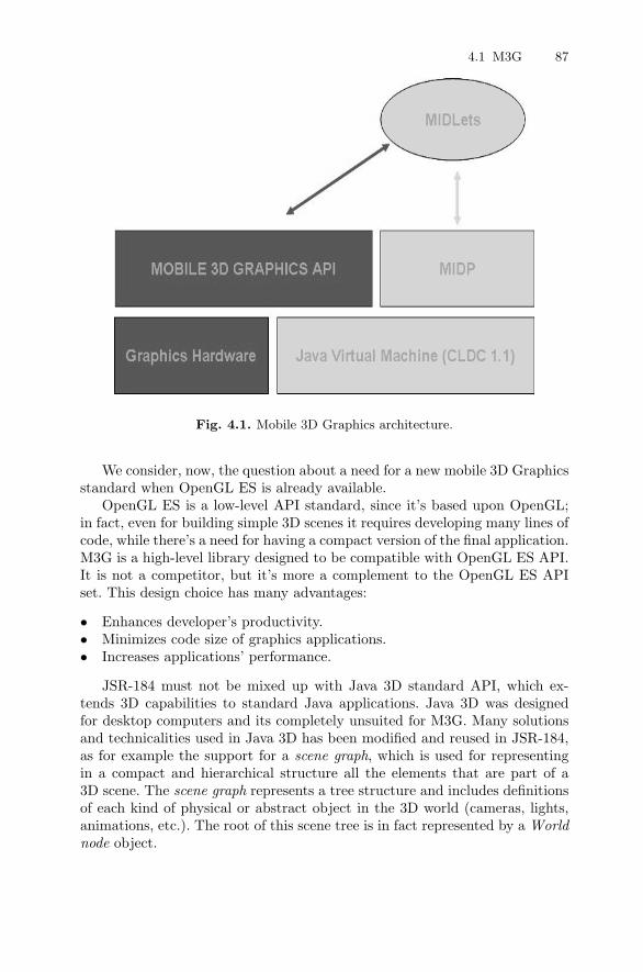
Even if a 3D Graphics API for Java already exists (JAVA3D), most mobiledevices have limited memory and processor power; thus Java 3D is unsuitablefor them. Therefore, a proposal for a more suitable API was put together by agroup of experts. The need was for a scalable, small-footprint, interactive 3DAPI for mobile devices that could work as an optional package for J2METMtoallow 3D graphics. Java Platform, Micro Edition or Java ME (formerly re-ferred to as Java 2 Platform, Micro Edition or J2ME), is a collection of JavaAPI for the development of software for resource constrained-devices such asPDAs, cell phones, and other consumer appliances. M3G is a software pack-age for providing 3D graphic functionalities to a wide range of devices(Figure4.1).
M3G is designed to be a 3D API suitable for the J2ME platform andCLDC [41]/MIDP [42].
Since it uses floats, it cannot be implemented on top of CLDC 1.0 butmust be implemented on at least version 1.1 of CLDC. The Connected LimitedDevice Configuration (CLDC) is a specification of a framework for Java MEapplications targeted at devices with very limited resources such as pagersand mobile phones. It could possibly be implemented on MIDP2 1.0, butmost devices supporting M3G will likely also support MIDP 2.0 [37]. It isintegrated with components of MIDP to allow efficient rendering to its Imageand Canvas classes.
1 JavaTMSpecification Requests (JSRs) are formal documents that describe pro-posed specifications and technologies to be added to the Java platform.
2 Mobile Information Device Profile (MIDP) is a specification published for the useof Java on embedded devices.
4.1 M3G 87
Fig. 4.1. Mobile 3D Graphics architecture.
We consider, now, the question about a need for a new mobile 3D Graphicsstandard when OpenGL ES is already available.
OpenGL ES is a low-level API standard, since it’s based upon OpenGL;in fact, even for building simple 3D scenes it requires developing many lines ofcode, while there’s a need for having a compact version of the final application.M3G is a high-level library designed to be compatible with OpenGL ES API.It is not a competitor, but it’s more a complement to the OpenGL ES APIset. This design choice has many advantages:
• Enhances developer’s productivity.• Minimizes code size of graphics applications.• Increases applications’ performance.
JSR-184 must not be mixed up with Java 3D standard API, which ex-tends 3D capabilities to standard Java applications. Java 3D was designedfor desktop computers and its completely unsuited for M3G. Many solutionsand technicalities used in Java 3D has been modified and reused in JSR-184,as for example the support for a scene graph, which is used for representingin a compact and hierarchical structure all the elements that are part of a3D scene. The scene graph represents a tree structure and includes definitionsof each kind of physical or abstract object in the 3D world (cameras, lights,animations, etc.). The root of this scene tree is in fact represented by a Worldnode object.
88 4 JavaTMMobile 3D Graphics
Moreover, JSR-184 specifications describe a new standard file format(.m3g), used for including all data related to a specific scene (the scene graph)and loading these data in applications coded to support the M3G standard. Inthis way, the scene data, including animations, can be created by using com-mon 3D modeling programs (Maya, 3D Studio, . . . ) available on the market.These models can then be saved in M3G format and imported in a M3G ap-plication program that, by using few lines of code, can visualize and animatethe imported scene. The product life cycle is thus tremendously accelerated bya clear separation between graphics design and code development of applica-tions. In fact, graphic artists can create their own look and feel for the scene,including animations, and then export them as an M3G file to applicationdevelopers.
4.2 MIDP Applications
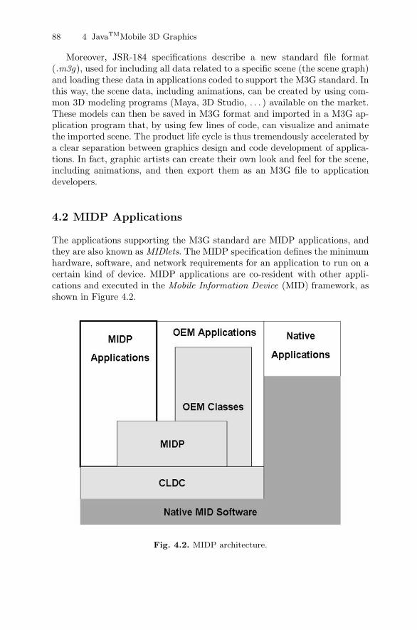
The applications supporting the M3G standard are MIDP applications, andthey are also known as MIDlets. The MIDP specification defines the minimumhardware, software, and network requirements for an application to run on acertain kind of device. MIDP applications are co-resident with other appli-cations and executed in the Mobile Information Device (MID) framework, asshown in Figure 4.2.
Fig. 4.2. MIDP architecture.
4.2 MIDP Applications 89
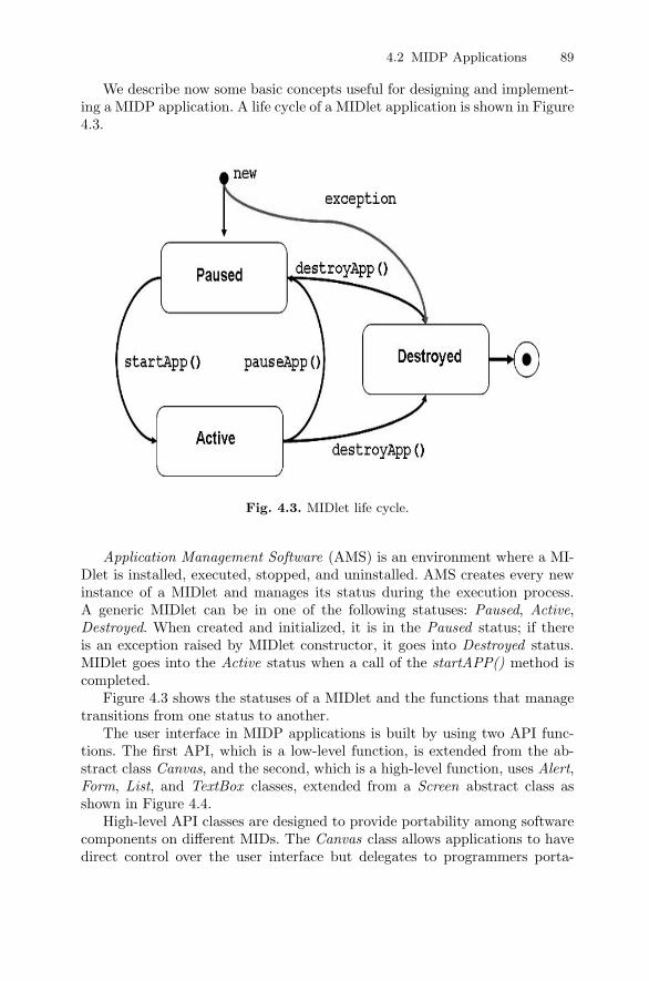
We describe now some basic concepts useful for designing and implement-ing a MIDP application. A life cycle of a MIDlet application is shown in Figure4.3.
Fig. 4.3. MIDlet life cycle.
Application Management Software (AMS) is an environment where a MI-Dlet is installed, executed, stopped, and uninstalled. AMS creates every newinstance of a MIDlet and manages its status during the execution process.A generic MIDlet can be in one of the following statuses: Paused, Active,Destroyed. When created and initialized, it is in the Paused status; if thereis an exception raised by MIDlet constructor, it goes into Destroyed status.MIDlet goes into the Active status when a call of the startAPP() method iscompleted.
Figure 4.3 shows the statuses of a MIDlet and the functions that managetransitions from one status to another.
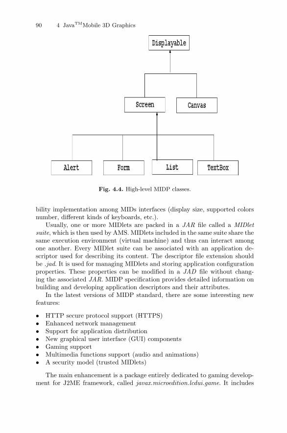
The user interface in MIDP applications is built by using two API func-tions. The first API, which is a low-level function, is extended from the ab-stract class Canvas, and the second, which is a high-level function, uses Alert,Form, List, and TextBox classes, extended from a Screen abstract class asshown in Figure 4.4.
High-level API classes are designed to provide portability among softwarecomponents on different MIDs. The Canvas class allows applications to havedirect control over the user interface but delegates to programmers porta-
90 4 JavaTMMobile 3D Graphics
Fig. 4.4. High-level MIDP classes.
bility implementation among MIDs interfaces (display size, supported colorsnumber, different kinds of keyboards, etc.).
Usually, one or more MIDlets are packed in a JAR file called a MIDletsuite, which is then used by AMS. MIDlets included in the same suite share thesame execution environment (virtual machine) and thus can interact amongone another. Every MIDlet suite can be associated with an application de-scriptor used for describing its content. The descriptor file extension shouldbe .jad. It is used for managing MIDlets and storing application configurationproperties. These properties can be modified in a JAD file without chang-ing the associated JAR. MIDP specification provides detailed information onbuilding and developing application descriptors and their attributes.
In the latest versions of MIDP standard, there are some interesting newfeatures:
• HTTP secure protocol support (HTTPS)• Enhanced network management• Support for application distribution• New graphical user interface (GUI) components• Gaming support• Multimedia functions support (audio and animations)• A security model (trusted MIDlets)
The main enhancement is a package entirely dedicated to gaming develop-ment for J2ME framework, called javax.microedition.lcdui.game. It includes

4.3 Immediate and Retained Mode 91
several classes that enable game developing for mobile devices [43]. In partic-ular, a GameCanvas class can be used in conjunction with an M3G standardon devices supporting MIDP version 2.0.
4.3 Immediate and Retained Mode
The main class for drawing a scene with M3G standard is the Graphics3Dclass. It is defined as a singleton 3 and a unique instance can be accessed viathe getInstance() method. To draw a scene, it is necessary to link a Graphics3Dinstance to a target object, draw the scene by an appropriate method, andrelease the target, as shown in the following snippet of code.
Graphics 3D g3g = Graphics3d . g e t In s tance ( ) ;World = world ; . . .Graphics g = . . .boolean bound = fa l se ;try {
g3d . bindTarget ( g ) ;bound = true ;g3d . render ( world ) ;
}f ina l ly {
i f ( bound ) g3d . r e l e a s eTarg e t ( ) ;}
A target object is a common Graphics object, the same as used in thepaint() method with a Canvas or a GameCanvas class.
Graphics3D can also draw on top of an Image2D object. In this way adeveloper can draw a three-dimensional scene and use it as texture. Note thattarget objects must be released after using them; otherwise a unique instanceof Graphics3D cannot be linked to other objects, and buffers cannot be sentto the screen for visualization.
Graphics3D supports two different drawing modalities:
1. Immediate mode• This is a low-level modality that allows defining each detail of a draw-
ing process.• It draws an individual node, a group of nodes, or a submesh in a scene
graph.• Cameras, lights, and background are managed separately.
2. Retained mode3 A one-time instantiated class with a unique point of access.
92 4 JavaTMMobile 3D Graphics
• This mode hides low-level details by loading and visualizing three-dimensional scenes by means of a few lines of code.
• It directly draws the World object, at the root of a scene graph.• It manages cameras, lights, and background by accessing them directly
with a World object.
The retained mode allows developers to use already-made, complex, threedimensional models; for instance, a developer can easily manage a scene graphin order to build a car model. Nodes representing wheels can rotate aroundtheir axes and are constrained to be parallel with respect to the car bodyorientation. All this information can be used by specifying it during modelingas additional information to nodes. The retained mode simplifies 3D worlddesign by hiding low-level technical details from developers.
The overall control of a 3D scene can be obtained only by using low-levelfunctions, and by accessing the graphics pipeline, and thus, for this reason,JSR-184 supports also the immediate mode, where drawing functions couldbe invoked on single objects. Moreover, the retained mode can take advantageof graphics acceleration because it is built on low-level immediate mode func-tions. Both modalities can be used in conjunction with each other, allowingdevelopers to balance drawing performance with resources by choosing theappropriate modality with respect to their target.
4.4 Scene Graph
The retained mode uses a scene graph for linking all geometric objects in athree-dimensional world made of a tree structure. Each node of the graphrepresents a geometric object and contains information on appearance, 4 po-sitioning in space, and function with respect to other nodes.
To build a 3D world, objects are used as subclasses of the Node base class.Then the Group class contains many objects, and the World class is a specialcase of the group class that includes all nodes in a scene. A World node is rootof the scene graph and it is different from a regular node, in that all specifiedtransformations are ignored during scene rendering.
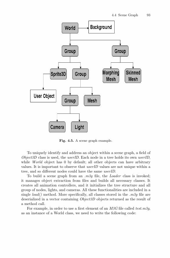
A 3D world can be created from scratch, and new nodes can be linked afterthat, but a more convenient procedure is storing a scene in an .m3g file andthen loading that scene to manage it in a scene graph. A complete and basicscene graph includes at least a World object and a Camera object. Figure 4.5shows a generic scene graph describing different node characteristics.
It also possible to share components among different nodes of a scenegraph, thus reducing memory usage. There are, anyway, some exceptions:
• Nodes can belong only to one group.• Cycles among nodes are not allowed.
4 It includes all geometric information concerning the node.
4.4 Scene Graph 93
Fig. 4.5. A scene graph example.
To uniquely identify and address an object within a scene graph, a field ofObject3D class is used, the userID. Each node in a tree holds its own userID,while World object has 0 by default; all other objects can have arbitraryvalues. It is important to observe that userID values are not unique within atree, and so different nodes could have the same userID.
To build a scene graph from an .m3g file, the Loader class is invoked;it manages object extraction from files and builds all necessary classes. Itcreates all animation controllers, and it initializes the tree structure and allgroup of nodes, lights, and cameras. All these functionalities are included in asingle load() method. More specifically, all classes stored in the .m3g file aredeserialized in a vector containing Object3D objects returned as the result ofa method call.
For example, in order to use a first element of an M3G file called test.m3g,as an instance of a World class, we need to write the following code:
94 4 JavaTMMobile 3D Graphics
Object3D [ ] o = null ;
try {o = Loader . load ( ” t e s t .m3g” ) ;
}
catch ( Exception e ) {}
World loaderWorld = (World ) o [ 0 ] ;
This class can also load many types of image formats, such as PNG, andin this case the result of the load method would be an Image2D object.
4.5 Transformations
The abstract class Transformable defines all geometric transformations thatcan be applied on nodes. There are four types of transformations:
• Translations (T)• Rotations (R)• Nonuniform scale (S).• Generic nonhomogeneous matrix 4 × 4 (M)
Given a point in the space p = (x, y, z, w), representing a vertex coordinateor a texture coordinate, its transformation can be defined (with respect to acoordinate system) as follows:
p′= TRSM × p
A Transformable class defines methods for setting these components, alsoindividually, as for example with the methods setTranslation() or setScale().
4.6 Nodes of the Scene Graph
The node class is an abstract class representing all kinds of nodes included ina scene graph, such as: lights, cameras, meshes, sprites, and groups. A nodedefines a local coordinate system that can be transformed with respect to itsancestor coordinates system. Nodes can also be lined up with other nodes orpoint to a reference node; in this way we can force, for instance, a light or acamera node to point to a fixed object.
Another interesting characteristic of a node is the ScopeID parameter.This field is used for setting the visibility levels of a node, and in general isused for computing the visibility of a set of objects. Many different kinds of
4.8 Managing Illumination 95
masks can be defined for the visibility of parts of a scene and to modify thescope of the camera in order to match the parts of a scene that are visible. Ifthe scope of a camera and the nodes do not match, the nodes aren’t drawnon the screen, thus saving resources especially at the computational level.
Moreover, this parameter can be used for speeding up computations onlighting. Usually, in a three-dimensional environment, the lights have a cer-tain radius, determined by the type of light and its intensity. By setting dif-ferent scopes for lights and objects corresponding to their distances, it can becomputed if a light has effects on that object or not. This allows the use ofmany different light sources in the same scene without affecting the speed ofperformances and saving computational resources.
A set of nodes can be grouped together by using a Group class. Groupingdifferent objects can help in the case of managing different objects with thesame kind of operations. A typical group example is a car model with fourwheels. In fact, by defining a car as a group of nodes, it is possible to movethe whole car without moving each wheel individually.
4.7 Camera Class
A camera class is represented by a node in a scene graph, which sets theposition of observers in the scene and the projection of a 3D perspective on atwo-dimensional display.
The camera is generally pointing toward negative values of the z axis. Itcan be positioned and oriented in the same way as other nodes, namely byusing transformations available at each node. It uses classical projections andclipping rules that apply for OpenGL, with the exception of the user-definedclipping planes, which are not supported. It is, instead, possible to definemany cameras, and thus it is posssible to have many different viewpoints.
4.8 Managing Illumination
The JSR-184 specification supports four kinds of lights, each having differentcomputational complexity and thus performance. The equations used for lightcomputation are directly imported from the OpenGL standard ones. Lighttypes are:
• Ambient light: defines the general intensity of objects in a scene. Ambientlights illuminate a scene with the same illumination quantity; thus positionand direction are ignored during computations.
• Directional light: defines only the source direction of light. Position ordistance from an object has no effect on the latter, even if it can be setanywhere in the scene.
96 4 JavaTMMobile 3D Graphics
• Omni light: defines a light source point. The omni lights affect objects ineach direction. A curve can be set to adjust the intensity variable accordingto the distance from objects.
• Spot light: defines the position, direction, and radius of a light cone. Thislight doesn’t have any effect on objects out of its light cone.
The computations needed to manage a light require a considerable amountof CPU time. It is thus crucial to choose the right kind of light related tothe scope of a scene and to avoid putting lights on every object by usinga scope node and thus saving computational performance. Every light has acolor determined by the RGB components and has an intensity value, but theexact effect of light hitting a surface is also function of that surface’s material.
4.9 Meshes and Sprites
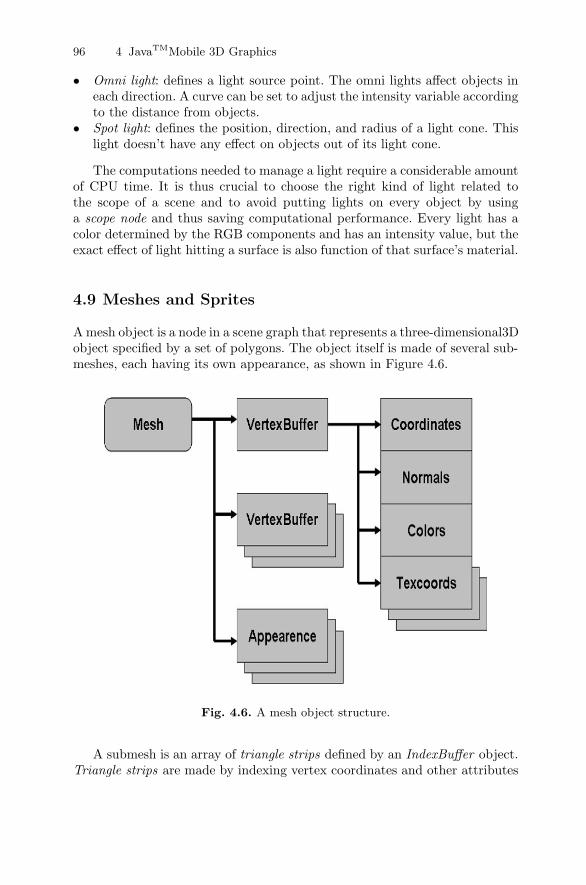
A mesh object is a node in a scene graph that represents a three-dimensional3Dobject specified by a set of polygons. The object itself is made of several sub-meshes, each having its own appearance, as shown in Figure 4.6.
Fig. 4.6. A mesh object structure.
A submesh is an array of triangle strips defined by an IndexBuffer object.Triangle strips are made by indexing vertex coordinates and other attributes
4.9 Meshes and Sprites 97
of a VertexBuffer associated with an IndexBuffer. VertexBuffer contains in-formation about vertex positions, normals, and texture coordinates. Each sub-mesh in a mesh shares the same VertexBuffer.
The components of an appearance object are:
• Material, which defines the colors to be used in lighting computations.• CompositingMode, which allows per-pixel composition attributes such as
transparencies and z-buffer.• PolygonMode, which contains attributes at the polygonal level including
settings for face visibility (back and front) and perspective corrections.• Fog, which contains all attributes for setting a fog effect.• Texture2D, which incorporates all 2D images and attributes for specifying
how an image can match the related submeshes.
The mesh class also includes two subclasses used for managing dynamicmeshes, which can change their shapes according to certain parameters: Mor-phingMesh and SkinnedMesh.
An object of MorphingMesh type is equivalent to an ordinary mesh, exceptthat its vertices are drawn and computed as a weighted linear combination.It is a combination of a VertexBuffer and VertexBuffers, which are targets ofthe morphing operation. All target VertexBuffers, also called morph targets,include the same properties: the same number of vertices for each array, thesame number of components per vertices, and the same component size.
By denoting a base mesh by B, morph targets by Ti, and weights for eachmorph target by wi, a resulting mesh can be represented by the followingequation:
R = B +∑
i wi(Ti − B)
Morphing can be computed on every vertex attribute:
• Vertex positions• Colors• Normals• Texture coordinates
The SkinnedMesh class represents a skeleton animated polygonal mesh.In contrast with a normal mesh class, it includes a skeleton structure. Theskeleton is built by means of a hierarchical structure, by using scene graphnodes. Each node belonging to a skeleton represents a bone, which is a trans-formation. Each vertex can be linked to one or more skeleton bones. In thisway a mesh is extended and linked to a structure that can manage it.
98 4 JavaTMMobile 3D Graphics
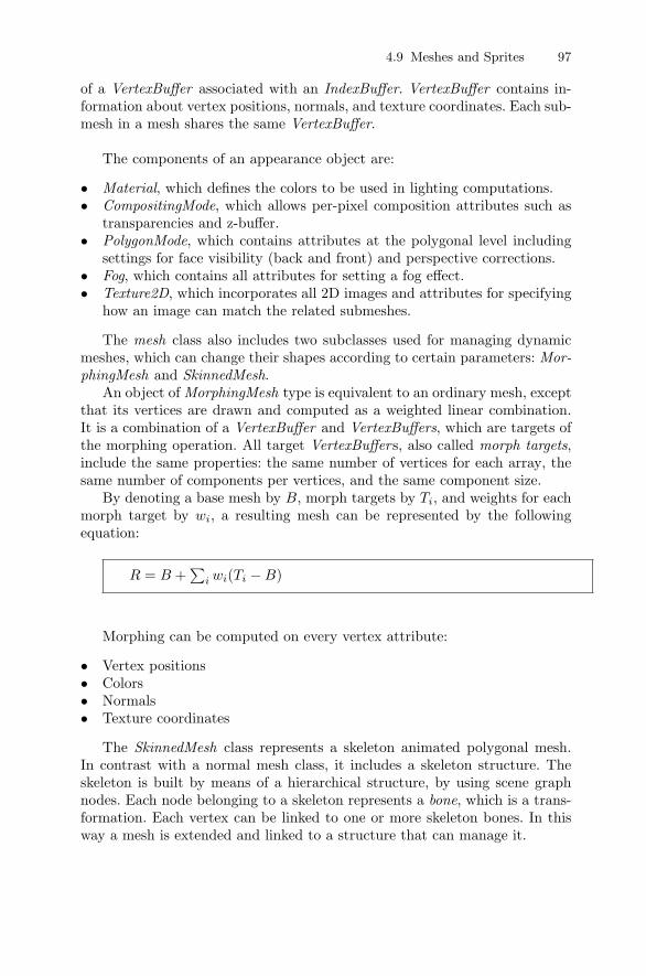
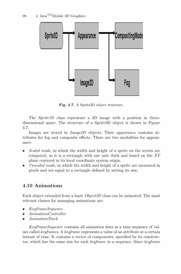
Fig. 4.7. A Sprite3D object structure.
The Sprite3D class represents a 2D image with a position in three-dimensional space. The structure of a Sprite3D object is shown in Figure4.7.
Images are stored in Image2D objects. Their appearance contains at-tributes for fog and composite effects. There are two modalities for appear-ance:
• Scaled mode, in which the width and height of a sprite on the screen arecomputed, as it is a rectangle with one unit thick and based on the XYplane centered in its local coordinate system origin.
• Unscaled mode, in which the width and height of a sprite are measured inpixels and are equal to a rectangle defined by setting its size.
4.10 Animations
Each object extended from a basic Object3D class can be animated. The mostrelevant classes for managing animations are:
• KeyFrameSequence• AnimationController• AnimationTrack
KeyFrameSequence contains all animation data as a time sequence of val-ues called keyframes. A keyframe represents a value of an attribute at a certaininstant of time. It contains a vector of components, specified by its construc-tor, which has the same size for each keyframe in a sequence. Since keyframe
4.10 Animations 99
values can be distant in time, interpolation functions are provided to managethem.
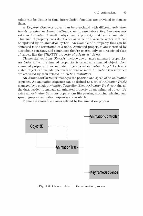
A KeyFrameSequence object can be associated with different animationtargets by using an AnimationTrack class. It associates a KeyFrameSequencewith an AnimationController object and a property that can be animated.This kind of property consists of a scalar value or a variable vector that canbe updated by an animation system. An example of a property that can beanimated is the orientation of a node. Animated properties are identified bya symbolic constant, and sometimes they’re related only to a restricted classof values, like the SHINESS property of a Material object.
Classes derived from Object3D include one or more animated properties.An Object3D with animated properties is called an animated object. Eachanimated property of an animated object is an animation target. Each ani-mated object can include references to zero or more AnimationTracks, whichare activated by their related AnimationControllers.
An AnimationController manages the position and speed of an animationsequence. An animation sequence can be defined as a set of AnimationTracksmanaged by a single AnimationController. Each AnimationTrack contains allthe data needed to manage an animated property on an animated object. Byusing an AnimationController, operations like pausing, stopping, playing, andspeeding-up an animation sequence are available.
Figure 4.8 shows the classes related to the animation process.
Fig. 4.8. Classes related to the animation process.
100 4 JavaTMMobile 3D Graphics
4.11 Ray Intersections
The RayIntersection class represents an infinite line starting from an origin(in a coordinate reference system) and pointing in a fixed direction. It is usedfor storing references to all Mesh or Sprite3D objects intersected by this line.Not only intersections but also distances between this line and intersectedobjects are stored. The RayIntersection object is created at run time andcannot be loaded by the Loader() class. It is used in conjunction with thepick() method of a Group class. This method returns information on this firstobject in a group intersected by the line passed as a parameter to this method.Information on intersected objects is then returned by the RayIntersectionobject. This class is used to manage collisions among objects or to simulate,for example, a gun-shot hitting a target placed at a fixed distance.
4.12 Building an M3G Demo
In this section we explore how to use some high-level classes provided by M3GAPI to create a simple demo program with a car model moving on the screenand avoiding obstacles by a collision detection method.
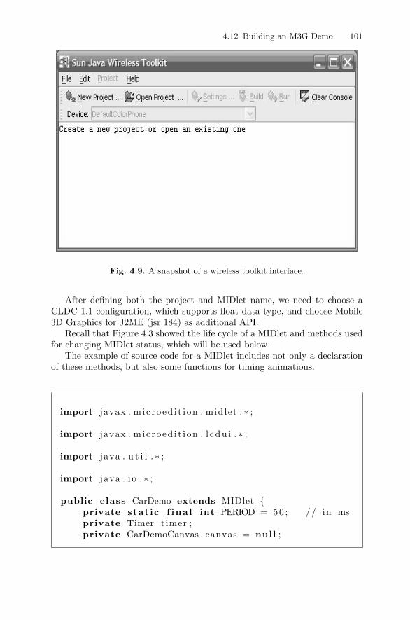
First we need to install a Sun Java Wireless Toolkit, and create a newproject by using a Ktoolbar interface. This will help in understanding appli-cations of the described concepts and classes.
4.12 Building an M3G Demo 101
Fig. 4.9. A snapshot of a wireless toolkit interface.
After defining both the project and MIDlet name, we need to choose aCLDC 1.1 configuration, which supports float data type, and choose Mobile3D Graphics for J2ME (jsr 184) as additional API.
Recall that Figure 4.3 showed the life cycle of a MIDlet and methods usedfor changing MIDlet status, which will be used below.
The example of source code for a MIDlet includes not only a declarationof these methods, but also some functions for timing animations.
import javax . m i c roed i t i on . mid let . ∗ ;
import javax . m i c roed i t i on . l c du i . ∗ ;
import java . u t i l . ∗ ;
import java . i o . ∗ ;
public class CarDemo extends MIDlet {private stat ic f ina l int PERIOD = 50 ; // in msprivate Timer t imer ;private CarDemoCanvas canvas = null ;
102 4 JavaTMMobile 3D Graphics
private Display d i sp l ay ;
public void pauseApp ( ) {}
public void destroyApp (boolean b){}
public Display getDisp lay ( ){
return d i sp l ay ;}
public void startApp ( ) {
// check whether m3g i s supported or notS t r ing ve r s i on =System . getProperty ( ” mic roed i t i on .m3g . v e r s i on ” ) ;i f ( v e r s i on == null ) {
f inishGame ( ) ;}
else {d i sp l ay = Display . getDi sp lay ( this ) ;
canvas = new CarDemoCanvas ( this ) ;t imer = new Timer ( ) ;
d i sp l ay . setCurrent ( canvas ) ;t imer . s chedu le ( new AnimTimer ( ) , 0 ,PERIOD) ;
}}public void f inishGame ( ) {
t imer . cance l ( ) ; // stop the t imernot i fyDes t royed ( ) ;
}
Inside the StartApp() method a microedition version property is checkedto indicate if the device supports additional m3g API. In case of a positiveanswer, the CarDemoCanvas class is initialized as the core class of our demoapplication.
In the same source code must be inserted a class called Animtimer thatis used for managing animations. This class contains a run method, which isin charge of updating animations. To set the timing for animations, a Timerclass has been used.
4.12 Building an M3G Demo 103
// Class f o r managing t imingclass AnimTimer extends TimerTask{
public void run ( ){ i f ( canvas != null )
canvas . update ( ) ;}
}
4.12.1 DemoCarCanvas Class
The DemoCarCanvas class extends the Canvas class and implements a Com-mandListener for managing the code to be executed in response to the EXITand BACK events generated by the device user’s interface.
The following snippet of code is a class constructor.
public CarDemoCanvas (CarDemo carDemo){
this . carDemo = carDemo ;
exitCmd = new Command( ”Exit ” ,Command.EXIT , 0 ) ;addCommand( exitCmd ) ;setCommandListener ( this ) ;
g3d = Graphics3D . ge t In s tance ( ) ;
width=getWidth ( ) ;he ight=getHeight ( ) ;
scene = new World ( ) ;
c r ea teScene ( ) ;
// s t a r t the animationnextTimeToAnimate = scene . animate ( appTime ) ;
}
104 4 JavaTMMobile 3D Graphics
First a reference to the MIDlet CarDemo is stored, and then the EXITcommand is set to allow users to close the application by pressing a devicekey.
After the Graphics3D object is instantiated, it represents a 3D graphicscontext and provides a method for scene drawing, called render.
The device screen height and width are set, and after the scene objectis created (the type of this object is World), it will contain all the three-dimensional scene objects (lights, cameras, and meshes).
Finally the createScene method is invoked for creating and setting allobjects included in the scene.
private void c rea teScene ( ) {createCar ( ) ;createCamera ( ) ;c r ea t eL i gh t ( ) ;createBackground ( ) ;c r e a t eF l oo r ( ) ;createCone ( ) ;
}
In CreateScene, many methods are called, one for each object included inthe three-dimensional scene.
In the scene we include:
• One camera (normCamera)• Two lights (light and light2)• One background (background)• Three meshes for visualizing a car, some cones (alias the obstacles), and a
floor
To load the mesh models in a three-dimensional scene, a technique has beendeveloped by Andrew Davison [44] which converts a wavefront OBJ model intoa Java class containing M3G code. We thus generated three different classes,Car, Floor, and Cone, including all visualization code for these three models.
A createCamera class sets up a simple camera, and we will use some trans-formations on this camera (mainly two 90-degree rotations with respect to thex and y axis) for visualizing the scene from the right perspective. To have abetter perspective, there is also a setOrientation method, which slides thescene down a little bit.
Finally a camera is added to the scene object and set as active.
private void createCamera ( ) {
f loat aspectRat io = ( f loat ) width / ( f loat ) he ight ;
4.12 Building an M3G Demo 105
// normCameranormCamera = new Camera ( ) ;normCamera . s e tPe r sp e c t i v e ( 6 0 . f , a spectRat io , 1 . 0 f ,100000. f ) ;
// camera t rans f o rmat i onsTransform normCameraTransform = new Transform ( ) ;normCameraTransform . postRotate ( 9 0 , 1 f , 0 f , 0 f ) ;normCameraTransform . postRotate ( 9 0 , 0 f , 1 f , 0 f ) ;
normCameraTransform . pos tTrans la te (0 f , 0 f , 2 0 0 . 0 f ) ;normCamera . setTransform ( normCameraTransform ) ;
// ang l e s downward s l i g h t l ynormCamera . s e tOr i en t a t i on (−50.0 f , 0 f , 1 f , 0 f ) ;
scene . addChild (normCamera ) ;scene . setActiveCamera (normCamera ) ;
}
Code that manages the lights also sets and uses the methods and propertiesof M3G API as shown below.
private void c r ea t eL i gh t ( ) {
// 1 omni l i g h t ( ahead )Light l i g h t = new Light ( ) ;l i g h t . s e tCo lo r (0 x f f f f f f ) ;
l i g h t . s e t I n t e n s i t y ( 1 . 0 f ) ;l i g h t . setMode ( Light .OMNI) ;l i g h t . s e tTran s l a t i on ( 0 , 0 , 1 0 0 ) ;
/ / 1 omni l i g h t ( behind )Light l i g h t 2 = new Light ( ) ;l i g h t . setMode ( Light .OMNI) ;l i g h t 2 . s e t I n t e n s i t y ( 1 . 0 f ) ;l i g h t 2 . s e tTran s l a t i on ( 1 0 0 , 1 0 0 , 1 0 0 ) ;
scene . addChild ( l i g h t ) ;scene . addChild ( l i g h t 2 ) ;
}
Very similar to the method above is the createBackground method codedas follows:
106 4 JavaTMMobile 3D Graphics
private void createBackground ( ) {
Background background = new Background ( ) ;
background . s e tCo lo r (0 x004080C0 ) ;
scene . setBackground ( background ) ;}
This method creates a background object, setting it to a light blue color.The color format is managed by M3G as 0xAARRGGBB, where:
• A stands for the alpha channel• R stands for the red channel• G stands for the green channel• B stands for the blue channel
The remaining methods, createCar, createCone, and createFloor, use theirrespective classes: Cone, Floor, and Car.
private void c r ea t eF l oo r ( ) {
Image2D f loo r Im = loadImage ( ”/ piano . png” ) ;Plane plane = new Plane ( f l oo r Im , 1 0 0 0 , 1 0 0 0 ) ;scene . addChild ( plane . getPlaneMesh ( ) ) ;
}
private void createCone ( ) {
Cone cone = new Cone ( ) ;Cone cone1 = new Cone ( ) ;cone . getMesh ( ) . s e tTran s l a t i on (100 , 130 , 30 f ) ;cone1 . getMesh ( ) . s e tTran s l a t i on (−150,−100,30 f ) ;scene . addChild ( cone . getMesh ( ) ) ;scene . addChild ( cone1 . getMesh ( ) ) ;
}
The createFloor and createCone classes, respectively, build a plane andtwo cones (obstacles), similar to street cones positioned in the scene.
The Plane class creates a 2D plane, and its constructor takes three pa-rameters as input:
4.12 Building an M3G Demo 107
• An Image2D object for managing textures• An integer representing x axis elongation• An integer representing y axis elongation
All images are loaded by the loadImage method, which performs someconsistency checks before returning an Image2D object as result.
private Image2D loadImage ( S t r ing fn ) {Image2D im = null ;try
{im = ( Image2D) Loader . load ( fn ) [ 0 ] ;
}catch ( Exception e ){
System . out . p r i n t l n ( ”Cannot make image from ” + fn ) ; }return im ;
}
The createCar method does not contain a Car class constructor, sincea car object is created during the initialization phase; it contains insteadmethods for managing collisions among car and other objects (street cones)in the scene:
• The setScene method takes a World object pointer to use it with the Carclass.
• The setPickingEnable method enables/disables a car mesh during collisioncomputations.
private void createCar ( ) {
// Disab le c o l l i s i o n de t e c t i on f o r car meshcar . getMesh ( ) . s e tP ick ingEnable ( fa l se ) ;
car . s e tScene ( scene ) ;
carGroup = car . getCarGroup ( ) ;
scene . addChild ( carGroup ) ;}
The update method is invoked for updating the car position on the screenafter checking for collisions by using the updateCar method of Car class. Oncea car is positioned, the screen is repainted by the repaint method.

108 4 JavaTMMobile 3D Graphics
public void update ( ) {appTime++;i f ( appTime >= nextTimeToAnimate ) {
nextTimeToAnimate = scene . animate ( appTime )+ appTime ;System . out . p r i n t l n ( ”nextTimeToAnimate : ”+ nextTimeToAnimate ) ;
}
car . updateCar ( ) ;
posCar = car . g e tPo s i t i on ( ) ;normCamera . s e tTran s l a t i on ( posCar [ 0 ] , posCar [ 1 ] ,
posCar [ 2 ] ) ;
r epa in t ( ) ;}
The paint method is in charge of drawing the final three-dimensional scene.As already mentioned, the only method provided by the M3G standard fordrawing is the render method; it can be called after linking a graphics contextto a canvas.
We also display on the screen the car speed (top left side of the screen).
protected void paint ( Graphics g ) {g3d . bindTarget ( g ) ;
g3d . render ( scene ) ;
g3d . r e l e a s eTarg e t ( ) ;
g . drawString ( ”Speed : ” + car . getSpeed ( ) , 5 , 5 ,Graphics .TOP| Graphics .LEFT) ;
}
The last two methods of the CarDemoCanvas class are used for managingthe keyboard.
protected void keyPressed ( int keyCode ) {int gameAction = getGameAction ( keyCode ) ;
car . pressedKey ( gameAction ) ;
4.12 Building an M3G Demo 109
}
protected void keyReleased ( int keyCode ) {int gameAction = getGameAction ( keyCode ) ;
car . re leasedKey ( gameAction ) ;}
Both methods check which key has been pressed, store it in a gameActionvariable, and pass it to Car class methods for updating the car position.
4.12.2 Car Class
Car class not only contains code for visualizing a car model (i.e., Floor andClone classes) but also has methods for animating cars, and manages (bymeans of the RayIntersect class) a basic collision detection algorithm.
The car class constructor takes an Image2D parameter for textures. It alsois in charge of building a car model and managing a group of transformations(trans) for positioning a car in the scene. The model is then linked to a group;in this way if we modify a transformation each of the children nodes is affectedby this change.
public Car ( Image2D img ) {this . s cene=scene ;
model = makeModel ( img ) ;
transGroup = new Group ( ) ;t rans . pos tTrans la te (X POS , Y POS , Z POS ) ;transGroup . setTransform ( t rans ) ;transGroup . addChild ( model ) ;
}
The storePosition method extracts the current car position from the trans-formations group.
private void s t o r ePo s i t i o n ( )// ex t r a c t the cur rent ( x , y , z ) p o s i t i o n from transGroup{
transGroup . getCompositeTransform ( t rans ) ;
t rans . get ( transMat ) ;xCoord = transMat [ 3 ] ;
110 4 JavaTMMobile 3D Graphics
yCoord = transMat [ 7 ] ;zCoord = transMat [ 1 1 ] ;
}
The transMat object represents a 4 × 4 float matrix:
private f loat [ ] transMat = new float [ 1 6 ] ;
The methods used for managing position and direction of the car are:
• updateMove, which takes a transformation parameter (trans), performsall checks for collision detection, and moves the car according to a spaceattribute computed by the current speed of the car.
• updateRotation, which by means of key pressed (left and right arrow keys)rotates the car (using a Transform object called rotTrans).
Both these methods are invoked by the updateCar method, which managesthe following:
• Increasing speed until the up arrow key is released, and decreasing speedwhen holding down the arrow key (or releasing both keys)
• Executing the updateMove method• Executing the updateRotation method only if the left or right arrow keys
are pressed
public void updateCar ( ) {
i f ( upPressed ) {i f ( speed<MAX SPEED) speed+=2f ;
}
i f ( downPressed ) {i f ( speed >0.0 f ) speed−=4f ;i f ( speed <0.0 f ) speed =0.0 f ;
}
i f ( ! upPressed && ! downPressed ) {i f ( speed >0.0 f ) speed−=2f ;i f ( speed <0.0 f ) speed =0.0 f ;
}
updateMove ( ) ;
i f ( l e f tP r e s s e d | | r i gh tPre s s ed )
4.12 Building an M3G Demo 111
updateRotation ( ) ;else i f ( ! l e f tP r e s s e d && ! r i gh tPre s s ed )
ang le =2.0 f ;}
All necessary attributes for managing key pressing (Boolean) are updatedby the pressedKey and releasedKey methods:
public void pressedKey ( int gameAction ) {switch ( gameAction ) {
case Canvas .UP: upPressed = true ; break ;case Canvas .DOWN: downPressed = true ; break ;case Canvas .LEFT: l e f tP r e s s e d = true ; break ;case Canvas .RIGHT: r i gh tPre s s ed = true ; break ;default : break ;
}}
public void re leasedKey ( int gameAction ) {switch ( gameAction ) {
case Canvas .UP: upPressed = fa l se ; break ;case Canvas .DOWN: downPressed = fa l se ; break ;case Canvas .LEFT: l e f tP r e s s e d = fa l se ; break ;case Canvas .RIGHT: r i gh tPre s s ed = fa l se ; break ;default : break ;
}}
We now describe the updateRotation method as coded below.
private void updateRotation ( ) {i f ( ang le<MAX ANGLE) ang le+=1.0 f ;
i f ( l e f tP r e s s e d ) { // ro t a t e l e f t around// the z−ax i s
rotTrans . postRotate ( ang le , 0 , 0 , 1 . 0 f ) ;zAngle += angle ;
}else { // ro t a t e r i g h t around the z−ax i s
rotTrans . postRotate(−ang le , 0 , 0 , 1 . 0 f ) ;zAngle −= angle ;
112 4 JavaTMMobile 3D Graphics
}
// angle va lue s are modulo 360 degree si f ( zAngle >= 360.0 f )
zAngle −= 360.0 f ;else i f ( zAngle <= −360.0 f )
zAngle += 360.0 f ;
// apply the z−ax i s r o t a t i on to transGroups t o r ePo s i t i o n ( ) ;t rans . s e t I d e n t i t y ( ) ;t rans . pos tTrans la te ( xCoord , yCoord , zCoord ) ;t rans . postRotate ( zAngle , 0 , 0 f , 1 f ) ;transGroup . setTransform ( t rans ) ;
}
Rotation takes place on the axis by changing the zAngle attribute, whichis increased or decreased by pressing the appropriate key. It is important tostore the rotation status in the Transform rotTrans object for keeping theinformation useful for the car direction vector.
The getDirection method computes the direction of the car.
public f loat [ ] g e tD i r e c t i on ( ) {
// zVec conta in s the i n i t i a l d i r e c t i o n o f the carf loat [ ] zVec = {− 1 , 0 , 0 , 0 } ;
// the exact d i r e c t i o n i s g iven a f t e r// computing the app l i ed r o t a t i o n s
rotTrans . trans form ( zVec ) ;
return new float [ ] { zVec [ 0 ] , zVec [ 1 ] , zVec [ 2 ] } ;}
The car direction is obtained by computing all the applied rotations. Cardirection is used for computing collision detection in the updateMove method.
Collisions are managed by using the RayIntersect class provided by theM3G standard. A RayIntersect object is set by the pick method, which ispart of the Group objects. RayIntersection stores a pointer to the intersectedMesh or Sprite3D, and to all the relevant information about the intersectionpoint.
4.12 Building an M3G Demo 113
The pick method first takes Mesh or Sprite3D into the group and enablesit for picking, which is intersected by a pick ray passed as a parameter (a rayis a line in our case).
The following is the code for the updateMove method. It is self-explanatory,as it includes comments:
private void updateMove ( ) {
transGroup . getTransform ( t rans ) ;
// computing space from speedspace=speed ∗0 .5 f ;
// check c o l l i s i o n sRayInte r s e c t i on r i = new RayInte r s ec t i on ( ) ;
// car d i r e c t i o n updatingd i r=ge tD i r e c t i on ( ) ;
// check whether the re i s something in f r on t// (Mesh or Sprite3D ) exc lud ing the car i t s e l f// and the f l o o r
i f ( scene . p ick (−1 , xCoord , yCoord , zCoord ,d i r [ 0 ] , d i r [ 1 ] , d i r [ 2 ] , r i ) ) {
// ob j e c t d i s t anc ef loat d i s t anc e = r i . ge tDi s tance ( ) ;
// 38 i s cone s i z e
i f ( d i s t ance >38.0 f + space ) {// movet rans . pos tTrans la te (− space , 0 , 0 ) ;transGroup . setTransform ( t rans ) ;
}else {
// stop the carspeed =0.0 f ;return ;
}}
114 4 JavaTMMobile 3D Graphics
// movet rans . pos tTrans la te (− space , 0 , 0 ) ;transGroup . setTransform ( t rans ) ;
}
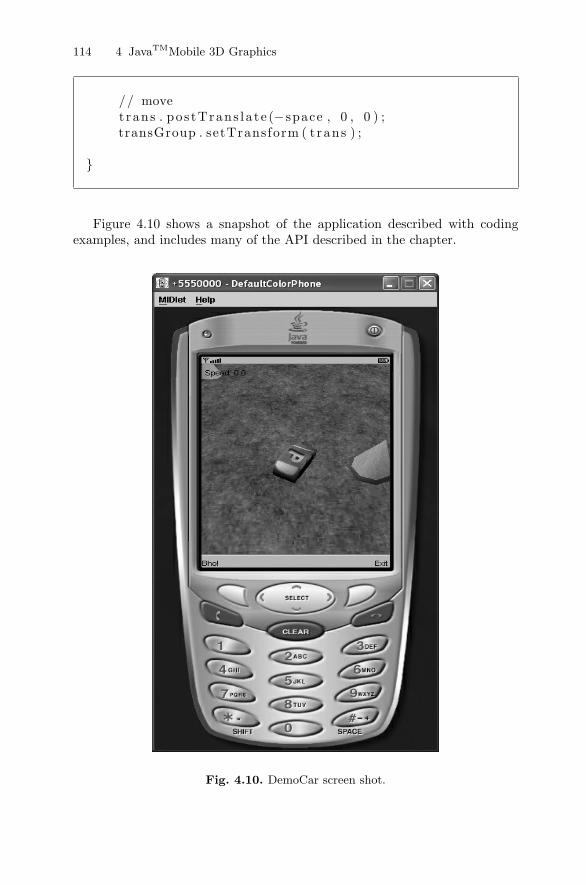
Figure 4.10 shows a snapshot of the application described with codingexamples, and includes many of the API described in the chapter.
Fig. 4.10. DemoCar screen shot.

4.13 Summary 115
4.13 Summary
This chapter introduced M3G and the Java Mobile 3D Graphics library, anddescribed how an application could be developed for mobile devices supportingthis standard.
We described also the frameworks (CLDC/MIDP) used by Java for man-aging mobile devices and applications. M3G is consider an extension of theselibraries and thus it is included in their development process. We also discussedthe modalities of M3G, Immediate and Retained mode, explaining when andhow to choose between the two. We then described elements of the M3G scenegraph, which is a hierarchical structure used by this library for representingand managing a 3D scene.
We finally provided a comprehensive example, called CarDemo, includingall the concepts, elements, and API that clarify the functionalities.