Embed Size (px)
Citation preview
EUROGRAPHICS 2001 / A. Chalmers and T.-M. Rhyne Volume 20 (2001), Number 3, pp. C-8–C-16(Guest Editors)
JAPE: A Prototyping System forCollaborative Virtual Environments
Oliver G. Staadt, Martin Näf, Edouard Lamboray, Stephan Würmlin
Computer Graphics GroupComputer Science Department
ETH Zurich, SwitzerlandE-mail: {staadt, naef, lamboray, wuermlin}@inf.ethz.ch
http://graphics.ethz.ch
AbstractWe present JAPE, a flexible prototyping system to support the design of a new advanced collaborative virtualenvironment. We describe the utilization of different hard- and software components to quickly build a flexible,yet powerful test bed for application and algorithm development. These components include a 3-D renderingtoolkit, live video acquisition, speech transmission, and the control of tracking and interaction devices. Tofacilitate the simultaneous design of applications and algorithms that take advantage of unique features of newcollaborative virtual environments, we provide the developer with a flexible prototyping toolkit which emulatesthe functionality of the final system. The applicability of JAPE is demonstrated with several prototype applica-tions and algorithms.
1. Introduction
Advanced virtual environments, such as spatially immer-sive displays (SIDs) 4, 9, make great demands on applica-tion programming interfaces, often referred to as virtualreality toolkits. This is due to special and often unique fea-tures provided by those environments that make it neces-sary to either extend existing multi-purpose toolkits or todesign new toolkits which are tailored to specific require-ments of the environment.
We are currently developing a novel collaborative virtualenvironment (CVE), the blue-c, which combines immersiveprojection with real-time video acquisition and advancedmultimedia communication 22. Eventually, multiple blue-cportals, connected via high-speed networks, will allowremotely located users to meet, communicate and collabo-rate in a shared virtual space.
The development of large immersive environments overthe past decade has revealed that good applications are cru-cial for the success of a VR system. Hence, instead ofadapting existing applications to a mere technology-focusedenvironment once it is completed, the application designershould be able to influence the development of the VR sys-tem right from the beginning 21.
Unfortunately, design and implementation of a full-fea-tured application programming interface (API) and theactual VR environment are often carried out simulta-neously. Thus, it is necessary to provide application design-ers with an alternative design and prototyping environmentthat emulates important features and concepts that willeventually be available in the final API. Moreover, it willprovide developers of core system components with a flexi-ble test bed for novel algorithms and methods.
Obviously, the provision of the prototyping environmentshould not be delayed until important design and implemen-tation decisions of the VR system have already been taken.Therefore, reuse of immediately available hard- and soft-ware components, which constitute the prototyping envi-ronment, allows for application design at an early stage ofthe project.
In this paper, we present JAPE, a prototyping environ-ment which has been built to support application design andalgorithm development for the blue-c project. Our goal isnot to introduce a novel system, but to reuse and combinesuitable components in short time. Note further that we donot intend to build our blue-c API directly on top of thisprototyping system. Some of the JAPE components, will
© The Eurographics Association and Blackwell Publishers 2001. Published by BlackwellPublishers, 108 Cowley Road, Oxford OX4 1JF, UK and 350 Main Street, Malden, MA02148, USA.
Staadt et al. / JAPE: A Prototyping System for Collaborative virtual Environments
eventually be integrated into the final API. This will ensurea smooth transition from JAPE to the blue-c API.
The remainder of this paper is organized as follows.After a brief summary of the blue-c project in Section 2, wediscuss related work in Section 3. Section 4 outlines the dif-ferent components comprising the prototyping environ-ment, followed by a detailed description of the core systemand individual components. The point-based renderingmethod introduced in Section 7 is an example for the inte-gration of a new component into JAPE. Finally, we presentsome prototype applications in Section 8.
2. The blue-c Project
The blue-c is a joint research project between several insti-tutes at ETH Zurich, including the Computer GraphicsGroup, the Center of Product Development, the ComputerAided Architectural Design Group, and the ComputerVision Group.
Our research aims at investigating a new generation of vir-tual design, modeling and collaboration environments. Theblue-c system foresees simultaneous acquisition of livevideo streams and projection of virtual reality scenes 22.Color representations with depth information of the userswill be generated using real-time image analysis. Thesehuman inlay representations will be integrated into a com-puter generated virtual scene, that will be projected in animmersive display environment. Thus, unprecedented inter-action and collaboration techniques among humans and vir-tual models will become feasible.
Several applications that take advantage of the novel fea-tures of the blue-c are currently being designed. Developersfrom different application fields, including architecture andmechanical engineering, utilize JAPE for the developmentof prototype applications and for the study of new interac-tion techniques. The final applications, however, will bedesigned for the blue-c platform. The blue-c project hasstarted in April 2000 and its first phase is expected to becompleted by spring 2003.
3. Related Work
During the past decade, many different architectures forbuilding virtual reality applications have evolved. We haveanalyzed a variety of commercial toolkits as well asresearch systems.
Commercially available toolkits include Sense8 (http://www.sense8.com/), which provides an easy to use interfacefor non technical users, and MultiGen-Paradigm Vega(http://www.multigen.com/), which offers powerful tools tocreate realistic worlds for real-time simulations, includingsensor simulation. Examples for non-commercial architec-tures are the VR-Juggler 1 and the MR Toolkit 20.
Recent research efforts concentrate on building distrib-uted virtual reality environments. Although various distrib-uted military simulations have been developed during thepast decade 3, 23, solutions for computer supported collabo-rative work (CSCW) in virtual reality environments is stillan area of very active research. A basic toolkit with focuson networking primitives, avatar handling and basic data-base functions in the CAVE 4 environment is CAVERNsoft10, 14. In addition, CAVERNsoft provides a set of Per-former-based high-level modules, which can accelerate theconstruction of collaborative virtual reality applications. Inthe future however, we plan to use advanced communica-tion technology and protocols with QoS support. CAVERN-soft, concentrating on TCP, UDP and HTTP, does not fulfillall the requirements we established for the blue-c system.
Avango 24 (a.k.a. Avocado) takes a different approach atdistributed virtual reality. It replicates a Performer scenegraph across all sites over the network. In addition to thisbase functionality, it supports a new scripting language forrapid application development. TELEPORT 2 is a tele-pres-ence system, which allows for the integration of a real per-son into a virtual office environment. A similar approach istaken with the Office of the Future project 17. Both systems,however, are currently restricted to uni-directional opera-tion.
The Distributed Interactive Virtual Environment(DIVE) 5 is a toolkit covering several important aspects ofvirtual environments, including graphics, audio and net-working. The MASSIVE System 6, developed at the Uni-versity of Nottingham, also provides a framework fordistributed virtual environments and puts special emphasizeon a spatial model of interaction for awareness manage-ment. MASSIVE and DIVE were both designed for Inter-net-based virtual environments with hundreds, or eventhousands of users. Hence their target applications are dif-ferent from those of the blue-c system, where only a fewsites will be interconnected via a high-speed network, andwhere the applications will run on high-end graphics hard-ware.
Ongoing research at the University of Manchester lead tothe development of novel techniques for display and inter-action management (Maverik) 8 as well as to an interestingparadigm for large-scale multi-user virtual environments(Deva) 15. The Deva implementation, which covers thecommunication aspects of the distributed virtual environ-ment, has not yet been released.
We have come to the conclusion that none of the abovetoolkits were immediately suitable for the blue-c withoutsignificant extensions and modifications. The final blue-capplication building toolkit will thus be built directly on topof OpenGL Performer. Consequently, we have decided notto employ any of those toolkits for the purpose of applica-tion design and prototyping.
© The Eurographics Association and Blackwell Publishers 2001.
Staadt et al. / JAPE: A Prototyping System for Collaborative Virtual Environments
4. System Overview
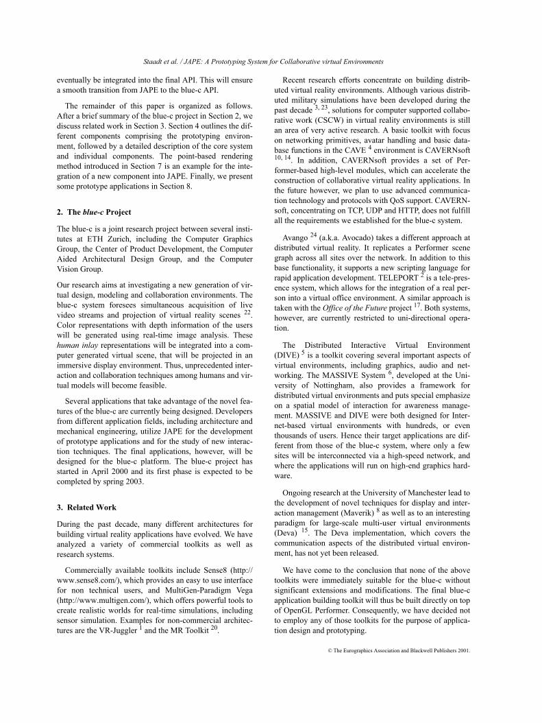
The JAPE environment comprises the system core and sev-eral interchangeable components for remote data acquisi-tion. See Figure 1 for a schematic overview of the JAPEarchitecture.
The system core is implemented using the OpenGL Per-former library, which provides basic functionality such asscene graph management and rendering. Currently, Per-former is the only library that efficiently supports multi-pipe rendering on an SGI Onyx, which is the target platformof the blue-c environment.
Three major components currently integrated with JAPEare video, audio and tracking. We have built a separateinterface, the InputServer, that connects these componentswith the core system. This enables us to hide implementa-tion details of the remote acquisition from the application.
A prototype application is built on top of the core systemthrough which it communicates with individual compo-nents. When the application is started, the core system ini-tiates the start of an InputServer instance on a number ofremote client hosts, which are responsible for data acquisi-tion and rendering (the rendering concept on remote clientswill be introduced in Section 5.2). Note that the applicationis responsible for importing scene information.
The core system functionality can further be extended byadding additional algorithms. One example is the integra-tion of a new point-based object as described in Section 5.4.
5. System Core5.1. Shared scene graph
In our prototype environment, we use a scene graph basedon the OpenGL Performer 2.4 library for storing and ren-dering the virtual scene. The development library includesthin wrapper classes for the scene graph, window manage-ment, and user interface elements such as mouse, keyboardand 3-D tracking devices. These are designed for rapidapplication prototyping while still allowing for direct accessto the underlying Performer interfaces for advanced devel-opers.
The prototype implements a pseudo-multiuser mode.Each user has his own view of the scene and user interface
devices such as keyboard, mouse and trackers or 3-D mice.The application code, however, runs within a single pro-cess. This application process maintains a single copy of thescene graph. User interface input is multiplexed sequen-tially, allowing for consistent scene graph updates withoutadditional synchronization.
5.2. Multi-head rendering
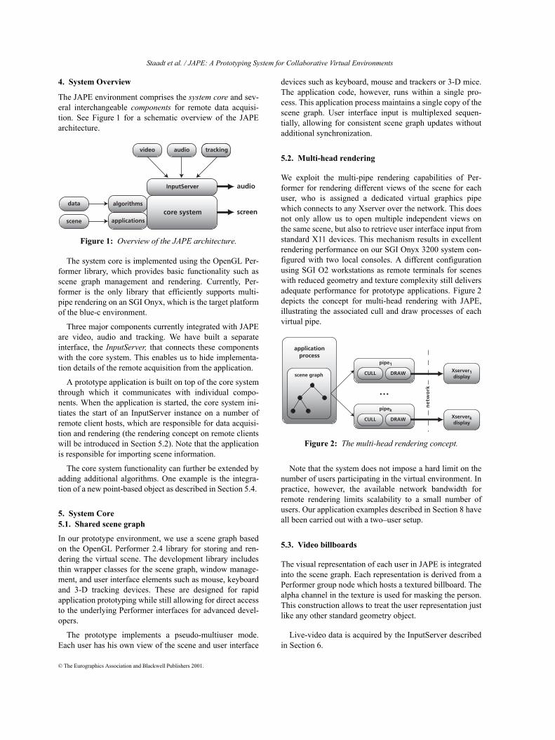
We exploit the multi-pipe rendering capabilities of Per-former for rendering different views of the scene for eachuser, who is assigned a dedicated virtual graphics pipewhich connects to any Xserver over the network. This doesnot only allow us to open multiple independent views onthe same scene, but also to retrieve user interface input fromstandard X11 devices. This mechanism results in excellentrendering performance on our SGI Onyx 3200 system con-figured with two local consoles. A different configurationusing SGI O2 workstations as remote terminals for sceneswith reduced geometry and texture complexity still deliversadequate performance for prototype applications. Figure 2depicts the concept for multi-head rendering with JAPE,illustrating the associated cull and draw processes of eachvirtual pipe.
Note that the system does not impose a hard limit on thenumber of users participating in the virtual environment. Inpractice, however, the available network bandwidth forremote rendering limits scalability to a small number ofusers. Our application examples described in Section 8 haveall been carried out with a two–user setup.
5.3. Video billboards
The visual representation of each user in JAPE is integratedinto the scene graph. Each representation is derived from aPerformer group node which hosts a textured billboard. Thealpha channel in the texture is used for masking the person.This construction allows to treat the user representation justlike any other standard geometry object.
Live-video data is acquired by the InputServer describedin Section 6.
Figure 1: Overview of the JAPE architecture.
core systemalgorithms
applications
InputServer
audio trackingtrackingvideo
screenscene
data
audio
Figure 2: The multi-head rendering concept.
applicationprocess
Xserver1display
pipe1
CULLscene graph
pipek
CULL
DRAW
DRAW Xserverkdisplay
...
ne
two
rk
© The Eurographics Association and Blackwell Publishers 2001.
Staadt et al. / JAPE: A Prototyping System for Collaborative virtual Environments
5.4. Point-based objects
In addition to application design, JAPE serves as a test bedfor new core algorithms. A first example is a point-basedrendering algorithm, which can be separated into two maincomponents:
• A new pseudo-geometry object which is added to thescene graph. From the perspective of the renderingsystem, the point-object is a unit cube around the ori-gin, which can be translated, scaled and rotated usingregular dynamic coordinate system (DCS) group trans-formation nodes. Runtime optimization such as viewfrustum culling can be applied safely.
• Calculation engines for each point-based object areinstantiated for each rendering channel. These enginescontinuously calculate new point sets depending oncurrent camera and viewport parameters as well asobject transformation. The parameters are updatedduring the culling phase for each frame. Callback rou-tines render the most recent result in the drawingphase.
The algorithm developer can easily plug different types ofimage warping or point rendering algorithms into thisframework without knowing the innards of Performer. Thismodel allows for easy compositing including correct occlu-sion handling as long as the object remains within the limitsof the unit cube.
5.5. Application integration
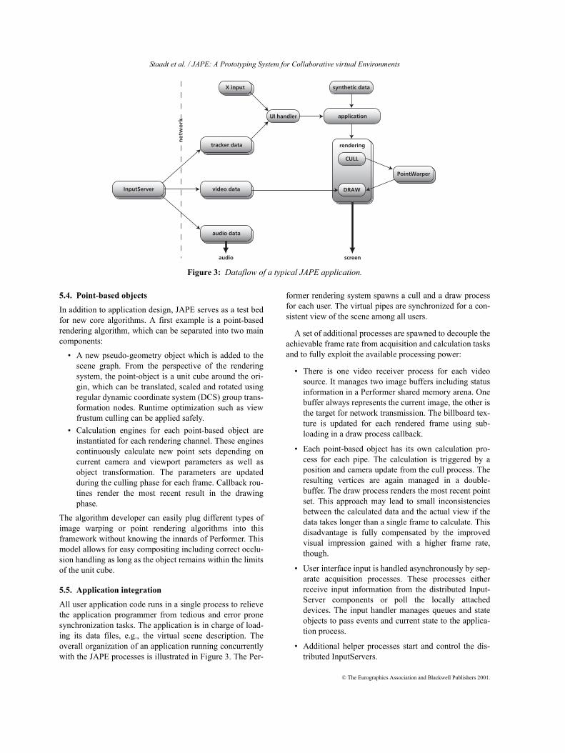
All user application code runs in a single process to relievethe application programmer from tedious and error pronesynchronization tasks. The application is in charge of load-ing its data files, e.g., the virtual scene description. Theoverall organization of an application running concurrentlywith the JAPE processes is illustrated in Figure 3. The Per-
former rendering system spawns a cull and a draw processfor each user. The virtual pipes are synchronized for a con-sistent view of the scene among all users.
A set of additional processes are spawned to decouple theachievable frame rate from acquisition and calculation tasksand to fully exploit the available processing power:
• There is one video receiver process for each videosource. It manages two image buffers including statusinformation in a Performer shared memory arena. Onebuffer always represents the current image, the other isthe target for network transmission. The billboard tex-ture is updated for each rendered frame using sub-loading in a draw process callback.
• Each point-based object has its own calculation pro-cess for each pipe. The calculation is triggered by aposition and camera update from the cull process. Theresulting vertices are again managed in a double-buffer. The draw process renders the most recent pointset. This approach may lead to small inconsistenciesbetween the calculated data and the actual view if thedata takes longer than a single frame to calculate. Thisdisadvantage is fully compensated by the improvedvisual impression gained with a higher frame rate,though.
• User interface input is handled asynchronously by sep-arate acquisition processes. These processes eitherreceive input information from the distributed Input-Server components or poll the locally attacheddevices. The input handler manages queues and stateobjects to pass events and current state to the applica-tion process.
• Additional helper processes start and control the dis-tributed InputServers.
Figure 3: Dataflow of a typical JAPE application.
ne
two
rk
rendering
DRAWvideo data
CULL
PointWarper
X input
tracker data
audio data
InputServer
UI handler
synthetic data
application
screenaudio
© The Eurographics Association and Blackwell Publishers 2001.
Staadt et al. / JAPE: A Prototyping System for Collaborative Virtual Environments
The asynchronous data acquisition adds a small latencypenalty because the available data is not always renderedimmediately. At high frame rates, however, this latencypenalty can be neglected, especially when considering thescene-update–to–render latency of three frames that isinherent to Performer in multi-processing mode.
5.6. Navigation and interaction
The development of the rapid prototype environment wasinitiated by the need for a test bed for new human-machineinteraction paradigms. As a consequence, the system doesnot provide high-level interaction tools. The system pro-vides only the raw input data such as mouse position, key-board events and tracker data in a real world coordinatesystem. Additional services for object picking are providedby Performer. It is up to the application developer to inter-pret the user interface input in order to navigate in and tointeract with the virtual world.
6. Remote Acquisition
The InputServer grabs live video images and tracker stateinformation, and streams them to the application host.Moreover, it handles audio conferencing with its partnersites, i.e., another workstation running an InputServer (seeFigure 3). The InputServer uses the Real-time TransportProtocol (RTP) 19 as its transport protocol above UDP/IP.We used Jori Liesenborgs’ RTP implementation jrtplib, ver-sion 2.3 (http://lumumba.luc.ac.be/jori/jrtplib/jrtplib.html).
6.1. Live video
Live video acquisition is carried out on SGI O2 worksta-tions with video option. The images of a user standing infront of a blue background are captured in RGBA format. Asimple chroma-keying is performed to extract the user’stexture. The RGB values of the background pixels can beset to the same value as their corresponding alpha value.This leads to long runs of identical byte values, which canbe compressed efficiently with run-length encoding. Afterthe acquisition and preprocessing steps, the image isstreamed to the application host.
For run-length encoding, we used the implementationfrom the SGI digital media library. We analyzed three testcases with different amounts of background pixels:
• The user’s body covers about 10–20 per cent of theinput image. This is a typical situation where the useris allowed to move during the session.
• The user’s body covers the complete image frame, i.e.,the user is tracked by a camera, or is not allowed tomove during the session.
• The image frame only covers the user’s head, whichwould be typical in a “video-conferencing” style appli-cation.
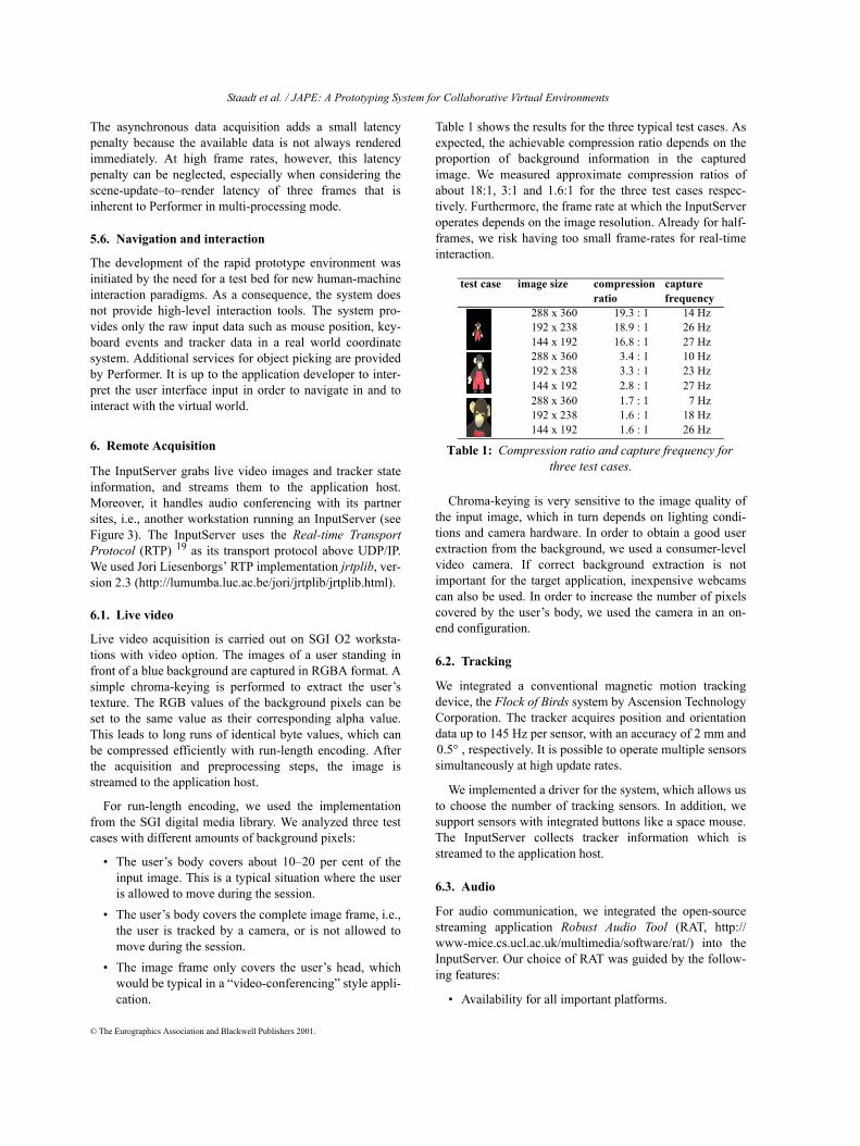
Table 1 shows the results for the three typical test cases. Asexpected, the achievable compression ratio depends on theproportion of background information in the capturedimage. We measured approximate compression ratios ofabout 18:1, 3:1 and 1.6:1 for the three test cases respec-tively. Furthermore, the frame rate at which the InputServeroperates depends on the image resolution. Already for half-frames, we risk having too small frame-rates for real-timeinteraction.
Chroma-keying is very sensitive to the image quality ofthe input image, which in turn depends on lighting condi-tions and camera hardware. In order to obtain a good userextraction from the background, we used a consumer-levelvideo camera. If correct background extraction is notimportant for the target application, inexpensive webcamscan also be used. In order to increase the number of pixelscovered by the user’s body, we used the camera in an on-end configuration.
6.2. Tracking
We integrated a conventional magnetic motion trackingdevice, the Flock of Birds system by Ascension TechnologyCorporation. The tracker acquires position and orientationdata up to 145 Hz per sensor, with an accuracy of 2 mm and
, respectively. It is possible to operate multiple sensorssimultaneously at high update rates.
We implemented a driver for the system, which allows usto choose the number of tracking sensors. In addition, wesupport sensors with integrated buttons like a space mouse.The InputServer collects tracker information which isstreamed to the application host.
6.3. Audio
For audio communication, we integrated the open-sourcestreaming application Robust Audio Tool (RAT, http://www-mice.cs.ucl.ac.uk/multimedia/software/rat/) into theInputServer. Our choice of RAT was guided by the follow-ing features:
• Availability for all important platforms.
test case image size compressionratio
capturefrequency
288 x 360 19.3 : 1 14 Hz192 x 238 18.9 : 1 26 Hz144 x 192 16.8 : 1 27 Hz288 x 360 3.4 : 1 10 Hz192 x 238 3.3 : 1 23 Hz144 x 192 2.8 : 1 27 Hz288 x 360 1.7 : 1 7 Hz192 x 238 1.6 : 1 18 Hz144 x 192 1.6 : 1 26 Hz
Table 1: Compression ratio and capture frequency for three test cases.
0.5°
© The Eurographics Association and Blackwell Publishers 2001.
Staadt et al. / JAPE: A Prototyping System for Collaborative virtual Environments
• Support of multi-party audio conferencing and use ofRTP as transport protocol above UDP/IP.
• Large range of different speech coding algorithmsfrom low-bandwidth linear prediction coding up tohigh-quality linear coding at 48 kHz sampling rate. Forsample recovery or substitution in case of packet loss,some advanced techniques like redundant or inter-leaved coding as well as receiver-based repair strate-gies are supported.
• The open-source distribution allows for seamless inte-gration of RAT into an application.
We linked RAT to the InputServer such that the audio con-ferencing application starts automatically without its owngraphical user-interface. The necessary user operations thatare normally required for starting listening using the work-station’s loudspeakers and talking using a separate micro-phone are all performed in software. The choice ofsampling frequency and of the audio codec as well as theplayback configuration are specified in RAT’s own configu-ration file.
Since we used the prototype only in a local-area-network,we chose linear encoding at 48 kHz without silence sup-pression. This produces a high quality audio stream at768 kbps per user. For this prototype environment, synchro-nization of audio and video streams is not required.
7. Rendering of Point-based Objects
The use of video billboards as described in Section 5.3 is asimple way of integrating dynamic real-world objects into athree-dimensional synthetic environment. The blue-c sys-tem, however, will eventually integrate point-based objectsthat are reconstructed form multiple live video streams intothe virtual environment. JAPE is used as a test bed forpoint-based rendering algorithms. We implemented a firstapproach to render static objects from multiple referenceimages with additional depth information using 3-D imagewarping 12. With this method we want to give a proof ofconcept for compositing 3-D point-based objects into thegeometry-based OpenGL Performer scene graph using theinterface provided by JAPE (see Section 5.4).
7.1. 3-D image warping
In order to render images with depth information, weadapted the 3-D image warping equation 12. Let be apoint in Euclidian space and be its projection onthe plane of image . The projection of into a newimage plane is given by
,
where denotes projective equivalence. is the cam-era’s center-of-projection associated with image and is its camera matrix. is the generalized disparity
of a source image pixel , which is defined by therange value of that point and its position to the center-of-projection:
.
The 3-D warping equation can be rewritten as rationalexpressions, which is computationally efficient and allowsfor incremental computations along individual scanlines.Note that the mapping of the 3-D warping equation is nothomeomorphic, thus, resolving visibility is required. Wehave implemented the technique proposed by McMillan andBishop 12, which essentially keeps a specific warping order,back-to-front, to resolve this problem. As an extension, weplan to implement a shear-warp factorization of the 3-Dwarping equation13 to further increase performance of thewarper by exploiting texture mapping hardware.
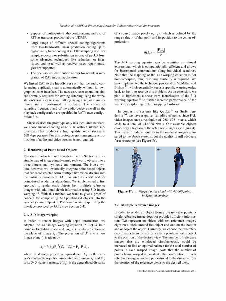
In contrast to systems like QSplat 18 or Surfel ren-dering 16, we have a sparser sampling of points since PALvideo images have a resolution of pixels, whichleads to a total of 442,368 pixels. Our example objectscover only a fraction of the reference images (see Figure 4).This leads to reduced quality in the rendered images com-pared to the above systems, but the quality is still adequatefor a prototype (see Figure 4b).
7.2. Multiple reference images
In order to render an object from arbitrary view points, asingle reference image does not provide sufficient informa-tion. We represent an object with ten reference images,eight on a circle around the object and one on the bottomand on top of the object. Currently, we choose the two refer-ence images from the nearest camera positions with respectto the position of the desired view. The number of referenceimages that are employed simultaneously could beincreased to find an optimal balance for the total number ofpoints in each warped image. Note that the number ofpoints being warped is constant. The contribution of eachreference image is inverse proportional to the distance fromthe position of the reference views to the desired view.
X·
us vs,( )is X·
it
xt δ xs( )Pt1– C· s C· t–( ) Pt
1– Psxs+=.
=. C· kik Pk
3 3× δ xs( )
Figure 4*: a: Warped point cloud with 45,000 points. b: Splatted surface.
us vs,( )r
δ xs( )Psxs
r-------------=
768 576×
(a) (b)
© The Eurographics Association and Blackwell Publishers 2001.

Staadt et al. / JAPE: A Prototyping System for Collaborative Virtual Environments
7.3. Surface reconstruction
Individual point samples are rendered using simple splatprimitives. In an initial implementation, we employed apush-pull filter 7 which leads to high quality images atreduced performance. We decided to implement a splattingin the fashion of QSplat, where the footprint of the splats isfixed and the splat size can be variable. In our example pro-totype, we used fixed splat sizes for better performance.
7.4. Integration and compositing
Our method represents objects from multiple images withdepth, which is similar to the concept of layered depthcubes 11. The goal of the blue-c is the real-time reconstruc-tion of humans and other real-world objects and their inte-gration into virtual environments. The described renderingtechnique is the first step towards that goal.
As described in Section 5.4, the warped object is insertedinto the scene graph as a point-based object. The point sam-ples are rendered very efficiently using glVertex primi-tives with splat size defined by glPointSize. Note thatthe OpenGL state change induced by glPointSize isexpensive and reduces the rendering performance by 50 percent. Thus, frequent changes of the splat size should beavoided. Table 2 lists performance measurements for thedifferent models shown in Figure 4b and Figure 5. Theframe rates were measured on a SGI Onyx 3200 using one400 MHz MIPS R12000 processor and a singleInfiniteReality3 pipe.
Note that the performance is proportional to the numberof points. When we render only a subset of 9,000 points ofthe woman model, we achieve a rate of 38 frames per sec-
ond. The resulting visual quality is sufficient for a movingobject.
8. Application Scenarios
8.1. Entertainment
Entertainment applications such as multi-user games arecommon scenarios for collaborative virtual environments.We have implemented a multi-user version of the popularMoorhuhn game (http://www.moorhuhn.de/).
Each user gets a view on the scene with chickens flyingin front of a background composed of several layers of tex-tured polygons. The chickens are simple textured polygons.Polygon vertices and texture coordinates are updated forevery frame for a smooth and dynamic flight.
The framework gathers mouse and keyboard input fromthe consoles of the players. Mouse and keyboard handlerobjects store interaction events for each user. The applica-tion main loop handles all input once per frame and updatesthe global scene and individual user views accordingly. Hit-testing is based on the Performer channel picking feature.
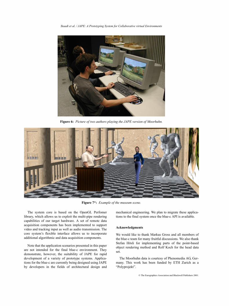
Making the game multi-user capable required very littleadditional development effort thanks to the shared scenegraph and trivial synchronization resulting therefrom.Figure 6 shows two people playing our multi-user versionof Moorhuhn.
8.2. Virtual museum
Tele-teaching and virtual guides are promising applicationareas for collaborative virtual environments. The traditionaltele-conferencing approach, which separates the representa-tion of the remote users and the data, leads to an unnaturalway of interaction. Recent immersive collaborative systemstherefore try to integrate all users directly into the scene.
The virtual museum example depicted in Figure 7, illus-trates the concept of an integrated video avatar as a tourguide, who explains the virtual exhibits to a point-basedvisitor. The position of the video billboard is given by thecamera position of the remote user. The users can eithernavigate with the keyboard, mouse or the 3-D tracker. Theusers can talk to each other over the audio system and keepeye contact, leading to a natural way of conversation withinthe virtual scene.
9. Conclusions
In this paper we presented JAPE, a flexible prototyping sys-tem for collaborative virtual environments. Instead ofemploying a complex VR toolkit that might not be suitablefor the final CVE, we demonstrated that it is possible tobuild a prototyping system from basic hard- and softwarecomponents. This enables us to provide application design-ers of the blue-c project with a development framework thatalready includes important components of the final system.
Figure 5*: Examples for point-based objects.a: Head. b: Teapot.
data set warpedpoints
fixedsplatting
variablesplatting
push-pullfilter
woman 45,000 18.0 fps 8.0 fps 3.5 fpshead 70,000 14.5 fps 4.5 fps 3.5 fpsteapot 120,000 12.0 fps 3.5 fps 2.5 fps
Table 2: Rendering performance for frame buffer resolution 768 x 576.
(a) (b)
© The Eurographics Association and Blackwell Publishers 2001.
Staadt et al. / JAPE: A Prototyping System for Collaborative virtual Environments
The system core is based on the OpenGL Perfomerlibrary, which allows us to exploit the multi-pipe renderingcapabilities of our target hardware. A set of remote dataacquisition components has been implemented to supportvideo and tracking input as well as audio transmission. Thecore system’s flexible interface allows us to incorporateadditional algorithmic and data acquisition components.
Note that the application scenarios presented in this paperare not intended for the final blue-c environment. Theydemonstrate, however, the suitability of JAPE for rapiddevelopment of a variety of prototype systems. Applica-tions for the blue-c are currently being designed using JAPEby developers in the fields of architectural design and
mechanical engineering. We plan to migrate these applica-tions to the final system once the blue-c API is available.
Acknowledgments
We would like to thank Markus Gross and all members ofthe blue-c team for many fruitful discussions. We also thankStefan Hösli for implementing parts of the point-basedobject rendering method and Rolf Koch for the head dataset.
The Moorhuhn data is courtesy of Phenomedia AG, Ger-many. This work has been funded by ETH Zurich as a“Polyprojekt”.
Figure 6: Picture of two authors playing the JAPE version of Moorhuhn.
Figure 7*: Example of the museum scene.
© The Eurographics Association and Blackwell Publishers 2001.
Staadt et al. / JAPE: A Prototyping System for Collaborative Virtual Environments
References
1. A. Bierbaum, C. Just, P. Hartling, and C. Cruz-Neira,"Flexible application design using VR Juggler". Tech-nical sketch presented at SIGGRAPH 2000, NewOrleans, July 2000.
2. C. J. Breiteneder, S. J. Gibbs, and C. Arapis. “TELE-PORT – An augumented reality teleconferencing envi-ronment.” Proceedings of EUROGRAPHICS VirtualEnvironments and Scientific Visualization '96, pp. 41–49, 1996.
3. M. Capps, D. McGregor, D. Brutzman, and M. Zyda.“NPSNET-V: A new beginning for virtual environ-ments.” IEEE Computer Graphics & Applications, pp.12–15, Sep./Oct. 2000.
4. C. Cruz-Neira, D. J. Sandin, and T. A. DeFanti. “Sur-round-screen projection-based virtual reality: Thedesign and implementation of the CAVE.” Proceedingsof SIGGRAPH 93, pp. 135–142, Aug. 1993.
5. E. Frécon and M. Stenius. “DIVE: A scalable networkarchitecture for distributed virtual environments.” Dis-tributed Systems Engineering Journal, 5, pp. 91–100,1998.
6. C. Greenhalgh, J. Purbrick, and D. Snowdown. “InsideMASSIVE-3: Flexible support for data consistency andworld structuring.” In Proceedings of CollaborativeVirtual Environments 2000, pp. 119–127, San Fran-cisco, September 2000.
7. J. P. Grossman and W. J. Dally. “Point sample render-ing.” In Proceedings 9th Eurographics Workshop onRendering, Rendering Techniques, pp. 181–192, 1998.
8. R.Hubbold, J.Cook, M.Keates, S.Gibson, T.Howard,A.Murta, A.West and S.Pettifer. “GNU/MAVERIK: Amicro-kernel for large-scale virtual environments.” InProceedings of ACM Symposium on Virtual RealitySoftware and Technology 1999 (VRST’99), London,pp. 66–-73, Dec. 1999.
9. E. Lantz. “The future of virtual reality: head mounteddisplays versus spatially immersive displays (panel).”In Proceedings of SIGGRAPH 96, pp. 485–486, Aug.1996.
10. J. Leigh, A. E. Johnson, and T. A. DeFanti. “CAV-ERN: A distributed architecture for supporting scalablepersistence and interoperability in collaborative virtualenvironments.” Journal of Virtual Reality Research,Development and Applications, 2(2), pp. 217–237,Dec. 1997.
11. D. Lischinski and A. Rappoport. “Image-based render-ing for non-diffuse synthetic scenes.” In Proceedings ofthe 9th Eurographics Workshop on Rendering 98, Ren-dering Techniques, pp. 301–314, 1998.
12. L. McMillan and G. Bishop. “Plenoptic modeling: Animage-based rendering system.” In SIGGRAPH 95
Conference Proceedings, ACM SIGGRAPH AnnualConference Series, pp. 39–46, 1995.
13. M. M. Oliveira, G. Bishop, and D. McAllister. “Relieftexture mapping.” In SIGGRAPH 2000 ConferenceProceedings, ACM SIGGRAPH Annual ConferenceSeries, pp. 359–368, 2000.
14. K. Park., Y. Cho, N. Krishnaprasad, C. Scharver, M.Lewis, J. Leigh, and A. Johnson. “CAVERNsoft G2: Atoolkit for high performance tele-immersive collabora-tion.” Proceedings of the ACM Symposium on VirtualReality Software and Technology 2000, Seoul, Korea,pp. 8–15, 2000.
15. S. Pettifer, J. Cook, J. Marsh and A. West. “DEVA3:Architecture for a large scale virtual reality system.” InProceedings of ACM Symposium on Virtual RealitySoftware and Technology 2000 (VRST’00), Seoul,October 2000.
16. H. Pfister, M. Zwicker, J. van Baar, and M. Gross.“Surfels: Surface elements as rendering primitives.” InSIGGRAPH 2000 Conference Proceedings, ACM Sig-graph Annual Conference Series, pp. 335–342, 2000.
17. R. Raskar, G. Welch, M. Cutts, A. Lake, L. Stesin, andH. Fuchs. “The office of the future: A unified approachto image-based modeling and spatially immersive dis-plays.” Proceedings of SIGGRAPH ‘98, pp. 179–188,July 1998.
18. S. Rusinkiewicz and M. Levoy. “QSplat: A Multireso-lution point rendering system for large meshes.” InSIGGRAPH 2000 Conference Proceedings, ACM Sig-graph Annual Conference Series, pp. 343–352, 2000.
19. H. Schulzrinne, S. Casner, R. Frederick, and V. Jacob-son. “RTP: A transport protocol for real-time applica-tions.” RFC 1889, January 1996.
20. C. Shaw, M. Green, J. Liang, and Y. Sun. "Decoupledsimulation in virtual reality with the MR Toolkit",.ACM Transactions on Information Systems, 11(3), pp.287–317, July 1993.
21. S. P. Smith and D. J. Duke. “Binding virtual environ-ments to toolkit capabilities.” Proceedings of EURO-GRAPHICS 2000, pp. C-81–C-89, 2000.
22. O. G. Staadt, A. Kunz, M. Meier, M. H. Gross. “Theblue-c: Integrating real humans into a networkedimmersive environment.” Proceedings of ACM Collab-orative Virtual Environments 2000, pp. 202–202, 2000.
23. “Standard for Modeling and Simulation (M&S) HighLevel Architecture (HLA) – Framework and rules.”IEEE Standard 1516, Sep. 2000.
24. H. Tramberend. “Avocado: A distributed virtual realityframework.” Proceedings of the IEEE Virtual Reality1999, pp. 14–21, 1999.
© The Eurographics Association and Blackwell Publishers 2001.