Embed Size (px)
Citation preview
January 8, 2005 Mike Hildreth – ILC-MDI Workshop
A BPM-Based Energy SpectrometerA BPM-Based Energy Spectrometer
Technical Considerations &Plans for the End Station A Test Beam
Mike Hildreth
University of Notre Dame
January 8, 2005 Mike Hildreth – ILC-MDI Workshop
A few words of Motivation:A few words of Motivation:
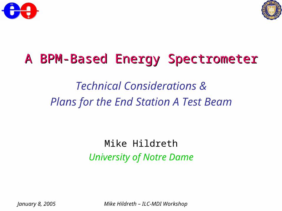
• Overall measurement precision is set by the expected statistical and systematic errors of “benchmark” measurements of mtop, mhiggs:
– require Ebeam/Ebeam ~ 100-200 ppm
– (LEP2 achieved ~170 ppm with a combination of techniques)• For an “Upstream” spectrometer, the only way we have been able to
devise a measurement which produces this accuracy and does ~nothing to the beam is a BPM-Based spectrometer, à la LEP:
ec B dp
~As built in LEP: 1998-2000
Spectrometer Magnet
Ancillary Magnet
= 1.9 mrad
0m 10m
2.5cm
BPMs
January 8, 2005 Mike Hildreth – ILC-MDI Workshop
This Talk…This Talk…
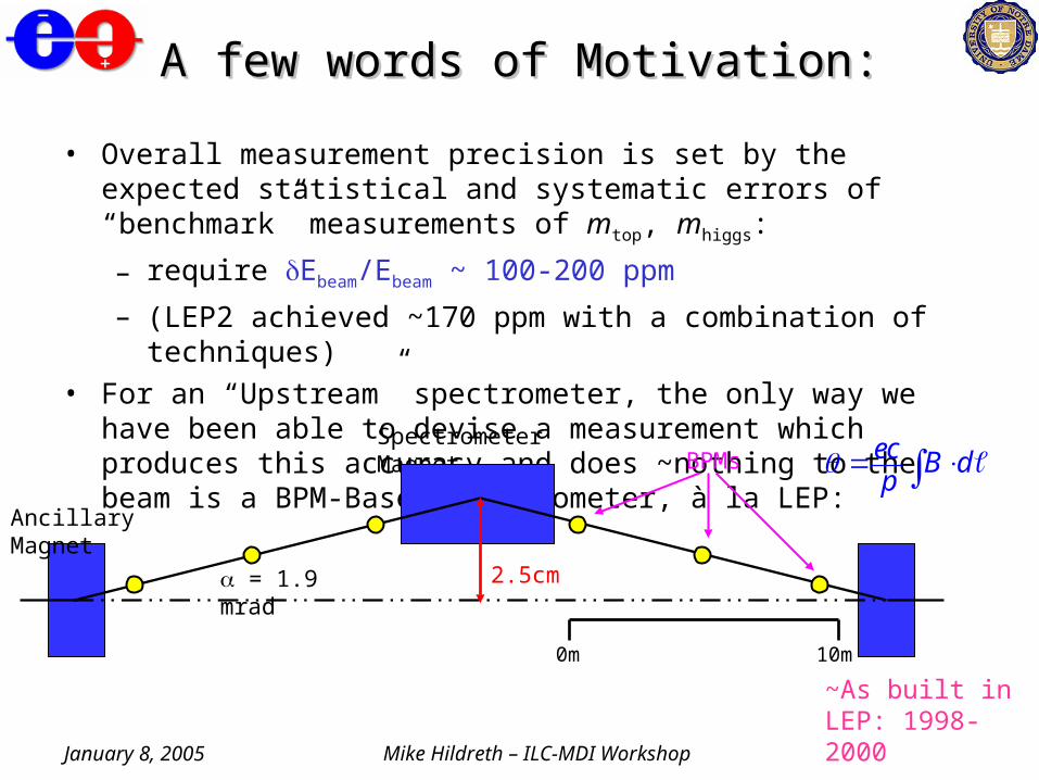
• Design Considerations for an ILC version of this technique– Constrained by allowed emittance growth from SR– Constrained by available real estate in BDS, overall size– Those constraints determine needed BPM resolution/stability– Other issues drive systematic errors, diagnostics– Must be robust, invisible to luminosity
• End Station A Beam Test Program (T474)– Goals– ESA Layout– Time scale for various tests
January 8, 2005 Mike Hildreth – ILC-MDI Workshop
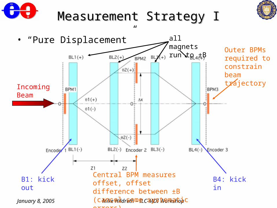
Measurement Strategy IMeasurement Strategy I
• “Pure Displacement”
Incoming Beam
B1: kick out B4: kick inCentral BPM measures offset, offset difference between ±B (cancel some systematic errors)
all magnets run to ±B Outer BPMs
required to constrain beam trajectory
January 8, 2005 Mike Hildreth – ILC-MDI Workshop
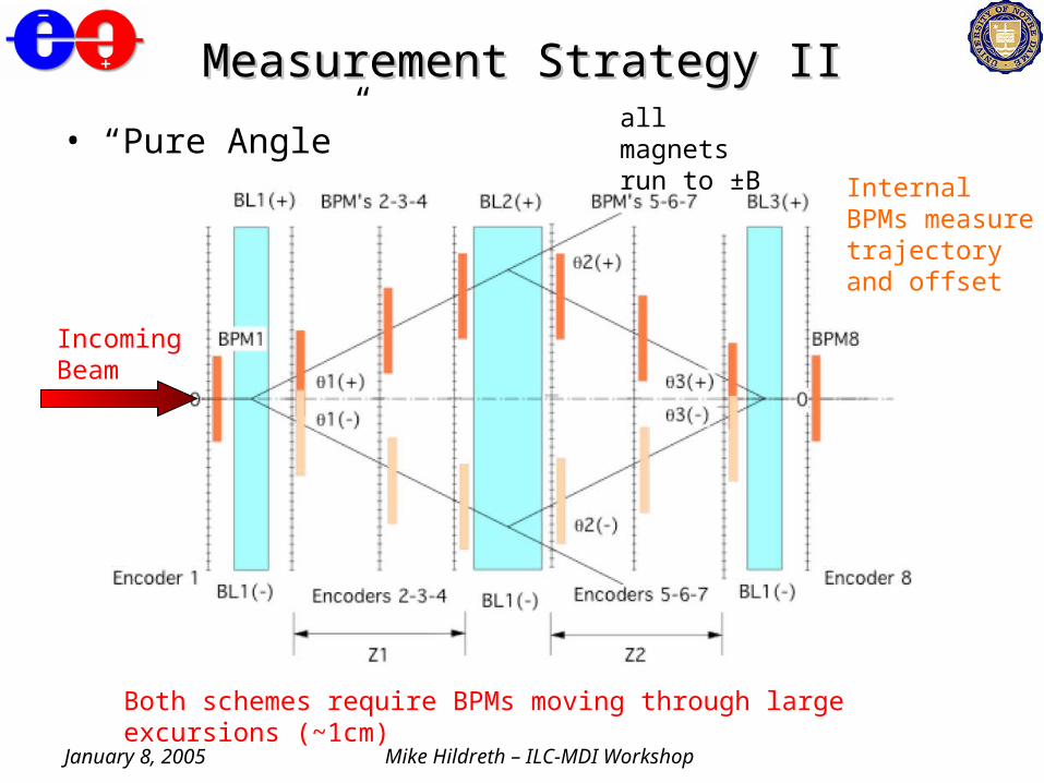
Measurement Strategy IIMeasurement Strategy II
• “Pure Angle”all magnets run to ±B
Internal BPMs measure trajectory and offset
Both schemes require BPMs moving through large excursions (~1cm)
Incoming Beam
January 8, 2005 Mike Hildreth – ILC-MDI Workshop
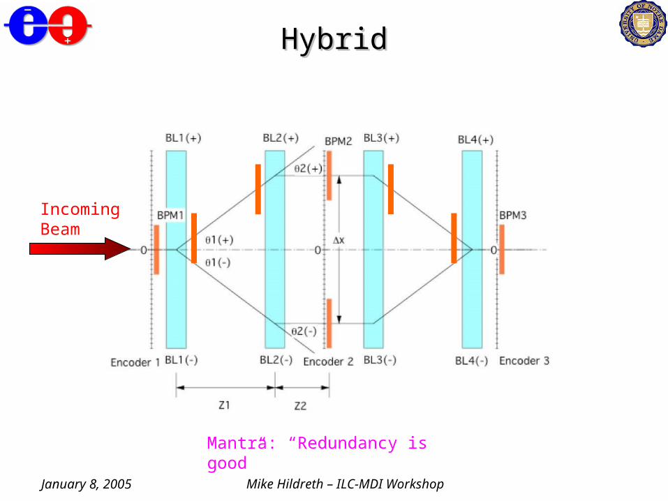
HybridHybrid
Incoming Beam
Mantra: “Redundancy is good”
January 8, 2005 Mike Hildreth – ILC-MDI Workshop
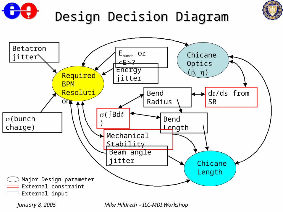
Design Decision DiagramDesign Decision Diagram
Required BPM Resolution
Chicane Length
Chicane Optics ()
d/ds from SRBend Radius
Bend Length(Bd)
Mechanical Stability
Beam angle jitter
Betatron jitter
(bunch charge)
Energy jitter
Major Design parameterExternal constraintExternal input
Ebunch or <E>?
January 8, 2005 Mike Hildreth – ILC-MDI Workshop
Emittance Growth in ChicaneEmittance Growth in Chicane
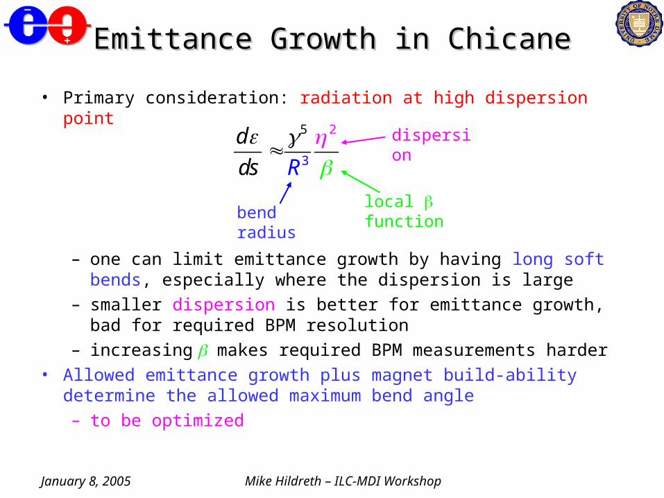
• Primary consideration: radiation at high dispersion point
– one can limit emittance growth by having long soft bends, especially where the dispersion is large
– smaller dispersion is better for emittance growth, bad for required BPM resolution
– increasing makes required BPM measurements harder• Allowed emittance growth plus magnet build-ability determine the
allowed maximum bend angle– to be optimized
5
3
2d
Rds
bend radiuslocal function
dispersion
January 8, 2005 Mike Hildreth – ILC-MDI Workshop
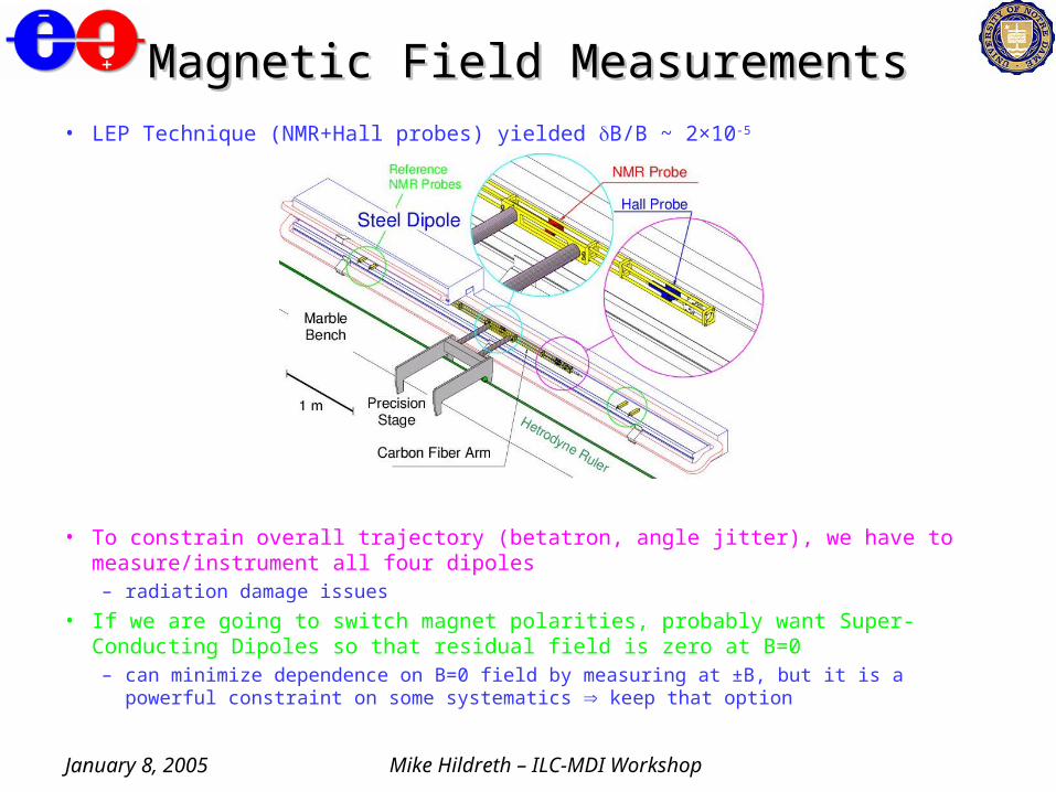
Magnetic Field MeasurementsMagnetic Field Measurements• LEP Technique (NMR+Hall probes) yielded B/B ~ 2×10⁻⁵
• To constrain overall trajectory (betatron, angle jitter), we have to measure/instrument all four dipoles– radiation damage issues
• If we are going to switch magnet polarities, probably want Super-Conducting Dipoles so that residual field is zero at B=0– can minimize dependence on B=0 field by measuring at ±B, but it is a powerful constraint
on some systematics keep that option

January 8, 2005 Mike Hildreth – ILC-MDI Workshop
Mechanical Stability IssuesMechanical Stability Issues
• Stability requirements determined by overall BPM resolution needed• Mechanical support structure must be designed to limit vibration,
and with minimal thermal expansion properties– how to cool? Custom temperature regulation needed...
• Stability must be monitored, for example:
– local positions determined by optical encoders on BPM movers
– global constraint on relative motion provided by stretched wire system
• at LEP, stretched wire was good to 130 nm (short) to 200 nm (long)
January 8, 2005 Mike Hildreth – ILC-MDI Workshop
Monitoring Mechanical StabilityMonitoring Mechanical Stability
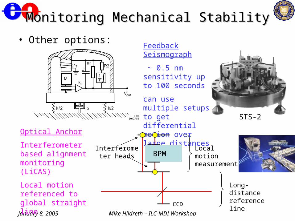
• Other options:Feedback Seismograph
~ 0.5 nm sensitivity up to 100 seconds
can use multiple setups to get differential motion over large distances STS-2
Optical Anchor
Interferometer based alignment monitoring (LiCAS)
Local motion referenced to global straight line
CCD
BPMLocal motion measurement
Long-distance reference line
Interferometer heads
January 8, 2005 Mike Hildreth – ILC-MDI Workshop
BPM MoversBPM Movers
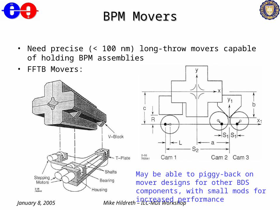
• Need precise (< 100 nm) long-throw movers capable of holding BPM assemblies
• FFTB Movers:
May be able to piggy-back on mover designs for other BDS components, with small mods for increased performance
January 8, 2005 Mike Hildreth – ILC-MDI Workshop
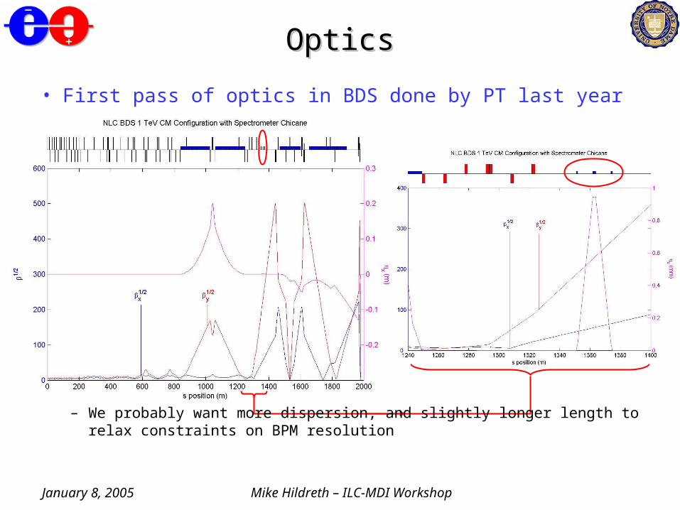
OpticsOptics
• First pass of optics in BDS done by PT last year
– We probably want more dispersion, and slightly longer length to relax constraints on BPM resolution
January 8, 2005 Mike Hildreth – ILC-MDI Workshop
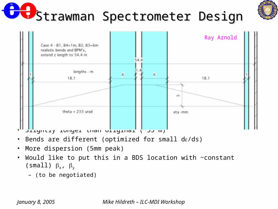
Strawman Spectrometer DesignStrawman Spectrometer Design
• Slightly longer than original (~55 m)• Bends are different (optimized for small d/ds)• More dispersion (5mm peak)
• Would like to put this in a BDS location with ~constant (small) x, y
– (to be negotiated)
Ray Arnold
January 8, 2005 Mike Hildreth – ILC-MDI Workshop
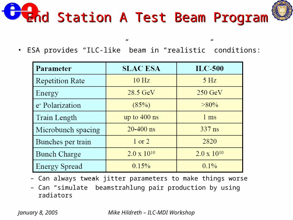
End Station A Test Beam ProgramEnd Station A Test Beam Program
• ESA provides “ILC-like” beam in “realistic” conditions:
– Can always tweak jitter parameters to make things worse
– Can “simulate” beamstrahlung pair production by using radiators
January 8, 2005 Mike Hildreth – ILC-MDI Workshop
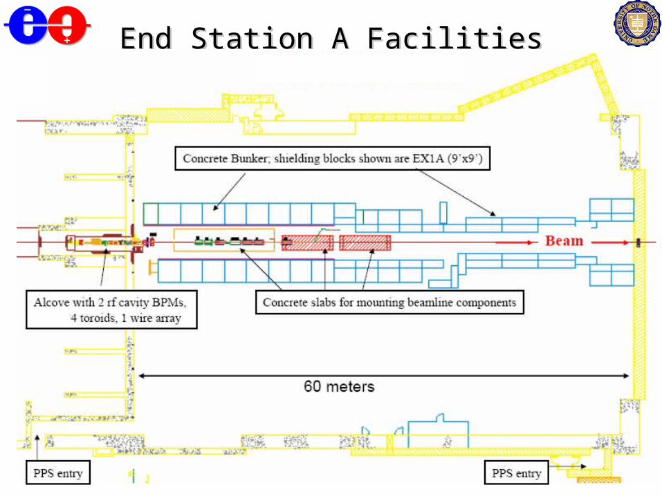
End Station A FacilitiesEnd Station A Facilities
January 8, 2005 Mike Hildreth – ILC-MDI Workshop
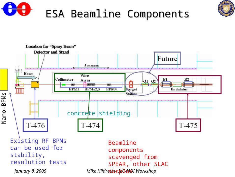
concrete shielding
ESA Beamline ComponentsESA Beamline Components
Existing RF BPMs can be used for stability, resolution tests
Beamline components scavenged from SPEAR, other SLAC surplus
Nan
o-B
PM
s
January 8, 2005 Mike Hildreth – ILC-MDI Workshop
T-474 Testbeam ProposalT-474 Testbeam Proposal
• Collaborators: Notre Dame, Berkeley, UCL, Cambridge, SLAC• Proposal submitted in June 2004• Goals:
– Establish a BPM system with electrical and mechanical stability at the 100 nanometer level
• sanity test for various components in “real” environment
– Eventually: Test energy measurement precision to verify feasibility of 100-200ppm measurement error
• cross check with T-475 (synchrotron stripe experiment) and spin precession in the A line
• UK institutions able to make substantial contributions in terms of people and M&S funds (from EuroTeV)
January 8, 2005 Mike Hildreth – ILC-MDI Workshop
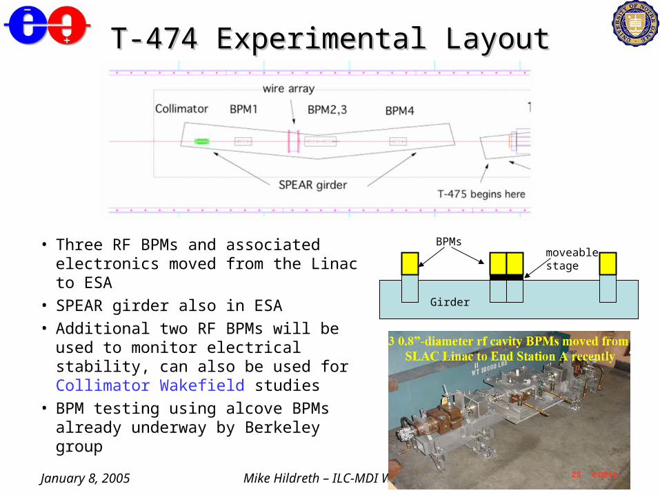
T-474 Experimental LayoutT-474 Experimental Layout
• Three RF BPMs and associated electronics moved from the Linac to ESA
• SPEAR girder also in ESA
• Additional two RF BPMs will be used to monitor electrical stability, can also be used for Collimator Wakefield studies
• BPM testing using alcove BPMs already underway by Berkeley group
moveable stage
BPMs
Girder

January 8, 2005 Mike Hildreth – ILC-MDI Workshop
T-474 Run PlansT-474 Run Plans
1. October/November? 2005: Establish Necessary Infrastructure
• Set up bunch-length measurements
• Set up wire scanner for emittance measurements
• Set up BPMs
• establish DAQ
• test for stability
• initial performance tests
• Some mechanical stability monitoring
• STS-2 Seismometer(s)
2. Late FY06/Early FY07?
• Install correctors before/after BPM girder to mimic spectrometer
• More advanced mechanical stability
• New BPM electronics?
3. Future
• Move towards full spectrometer demonstration project
(still evolving)
January 8, 2005 Mike Hildreth – ILC-MDI Workshop
ConclusionsConclusions
• Spectrometer CDR well underway– Thanks to Ray Arnold– Design advancing
• many parameters to consider• built-in redundancy will be key
– need optics design soon to make headway on technical requirements for Spectrometer components
• “Trust, but Verify”– Beam Tests are critical for these systems
• tolerances are very tight, many surprises are possible