Embed Size (px)
Citation preview
AD
* TECHNICAL REPORT ARCCB-TR-89003
ANALYSIS OF A LARGE HIGH
PRESSURE VESSEL CL OSURE
'
G. P. O'HARAC\ DTIC
MR 101989
Db
JANUARY 1989
US ARMY ARMAMENT RESEARCH,_ DEVELOPMENT AND ENGINEERING CENTER
CLOSE COMBAT ARMAMENTS CENTERBEN]T LABORATORIES
WATERVLIET, N.Y. 12189-4050
APPROVED FOR PUBLIC RELEASE; DISTRIBUTION UNLIMITED
P89 3 10 048

DISCLAIMER
The findings in this report are not to be construed as an official
Department of the Army position unless so designated by other authorized
documents.
The use of trade name(s) and/or manufacturer(s) does not constitute
an official indorsement or approval.
DESTRUCTION NOTICE
For classified documents, follow the procedures in DoD S200.22-M,
Industrial Security Manual, Section 11-19 or DoD S200.l-R, Information
Security Program Regulation, Chapter IX.
For unclassified,. limited documents, destroy by any method that will
prevent disclosure of contents or reconstruction of the document.
For unclassified, unlimited documents, destroy when the report is
no longer needed. Do not return it to the originator.
SECURITY CLASSIFICATION OF THIS PAGE (Wmhn Data Entere)
REPORT DOCUMENTATION PAGE RED CSTRUCTINOSBEFORE COM, LETING FORM
1. REPORT NUMBER 2. GOVT ACCESSION NO. 3. RECIPIENT'S CATALOG NUMBER
ARCCB-TR-89003
4. TITLE (and Subtttlo) S. TYPE OF REPORT & PERIOD COVERED
ANALYSIS OF A LARGE HIGH PRESSURE VESSEL CLOSURE Final
6. PERFORMING ORG. REPORT NUMBER
7. AUTHOR(&) 8. CONTRACT OR GRANT NUMBER()
S. P. O'Hara
S. PERFORMING ORGANIZATION NAME AND ADDRESS 10. PROGRAM ELEMENT, PEOJECT, TASK
U.S. Army ARDEC AREA & WORK UNIT NUMBERS
Benet Laboratories, SMCAR-CCB-TL AMCMS No. 6126.24.H190.011
Watervliet, NY 12189-4050 PRON No. A18219llAllA
1. CONTROLLING OFFICE NAME AND ADDRESS 12. REPORT DATE
U.S. Army ARDEC January 1989Close Combat Armaments Center 13. NUMBER OF PAGESPicatinny Arsenal, NJ 07801-5000 18
14. MONITORING AGENCY NAME & ADORESS(JI dillerent hom Canolllne Office) IS. SECURITY CLASS. (of thl. report)
UNCLASSIFIED
ISa. DECLASSI FICATION/DOWNGRADINGSCHEDU LE
16. DISTRIBUTION STATEMENT (of ths Report)
Approved for public release; distribution unlimited.
17. DISTRIBUTION STATEMENT (of the abatract entered In Block 20, It different frao Report)
1S. SUPPLEMENTARY NOTES
Presented at the 1988 ASME Pressure Vessel and Piping Conference,Pittsburgh, PA, June 1988.Published in Proceedings of the Conference.
19. KEY WORDS (Continue m revme aide If neceeary and identify by block nmber)
Pressure Vessels'Stress r. ,ContactScrew Threads,
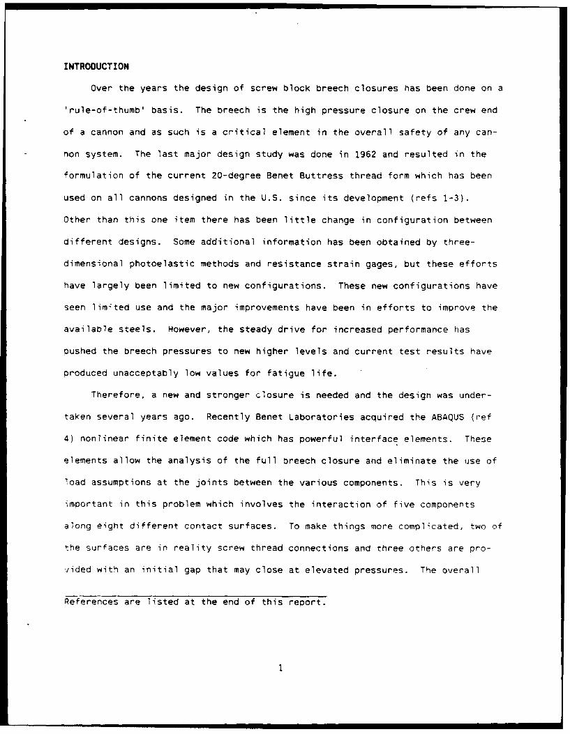
20L AtACT ..Ct-i., , ,ewi e N tieemy old -d,,-,, by block nmtber)
TheL-Asi2;n of the end -1osure for a high pressure vessel is never an easy task.However, in this case it is complicated by a requirement for quick operationand high reliability. The configuration which has best proven itself manytimes is the screw block breech. This report covers an analysis of thisclosure which is a fiv.e-body problem. The problem is further complicated bythe fact that the bodies interact on eight contact surfaces. This analysiswill point to a fatigue failure at a single point in the structural system.
DD I n EDITION or I NOVS is OBSOLETE UNCLASSIFIED
SECURITY CLASSIFICATIOM OF THIS PAGE (Wei Doe. Entered)
. . . . ,, , , u u a a I I I I I

TABLE OF CONTENTS
INTRDUCION.................................................
GETOET.................................................................2
LOADS AND CONSTRAINTS...................................................... 3
CONTACT SURFACES........................................................... 4
SCREW THREAD SURFACES...................................................... 4
THREAD FILLET STRESSES..................................................... 5
RESULTS ................................................................... 6
DISCUSSION ................................................................ 7
CONCLUSIONS ............................................................... 9
REFERENCES............................................................... 10
LIST OF ILLUSTRATIONS
1. Exploded outline of the components.....................................11i
2. Undeformed finite element mesh......................................... 12
3. Deformed mesh plot .................................................... 13
4. Contour plot of the smallest principal stress.......................... 14
5. Contour plot of the intermediate principal stress.......................15
6. Contour plot of the largest principal stress........................... 16
7. Calculated screw thread fillet stresses................................ 17
~AC- -ior, For
NTIS CRA2-DTIC TAB]
A ~By __
Dist
INTRODUCTION
Over the years the design of screw block breech closures has been done on a
'rule-of-thumb' basis. The breech is the high pressure closure on the crew end
of a cannon and as such is a critical element in the overall safety of any can-
non system. The last major design study was done in 1962 and resulted in the
formulation of the current 20-degree Benet Buttress thread form which has been
used on all cannons designed in the U.S. since its development (refs 1-3).
Other than this one item there has been little change in configuration between
different designs. Some additional information has been obtained by three-
dimensional photoelastic methods and resistance strain gages, but these efforts
have largely been limited to new configurations. These new configurations have
seen limited use and the major improvements have been in efforts to improve the
available steels. However, the steady drive for increased performance has
pushed the breech pressures to new higher levels and current test results have
produced unacceptably low values for fatigue life.
Therefore, a new and stronger closure is needed and the design was under-
taken several years ago. Recently Benet Laboratories acquired the ABAQUS (ref
4) nonlinear finite element code which has powerful interface elements. These
elements allow the analysis of the full breech closure and eliminate the use of
load assumptions at the joints between the various components. This is very
important in this problem which involves the interaction of five components
along eight different contact surfaces. To make things more complicated, two of
the surfaces are in reality screw thread connections and three others are pro-
vided with an initial gap that may close at elevated pressures. The overall
References are listed at the end of this report.
... . . .' l~m. m,, l lmI m ill li I lll • I I I 1

result is that the problem becomes nonlinear because the state of the contact
surfaces can vary with load. These variations are indeed a reality as they are
in many other threaded connection problems.
The analysis reported here includes some of the results from the first
major analysis of a complete breech closure. The analysis was done as an axi-
symmetric solution and yielded information on several features of the structure
that had never been considered before. These new effects were found in 6p te of
the fact that the structure is not actually axisymmetric and the analysis must
ignore two design features which would require full three-dimensional analysis.
First is the helix angle of the screw threads, which would not seem to result in
a large error. The second item is that the screw threads are interrupted
threads to allow for faster operation between pressure cycles. In this process
about one-half of the threads have been removed in four areas around the pitch
cylinder of the threads, resulting in an overall reduction in the threaded
surface of about 50 percent. Along with this area reduction is a periodic
variation in deformations as strain gage results plotted around the central axis
of the closure. This effect has not been reported for this system, however, 4z
was reported for a similar one by this author in a photoelastic study (ref 5).
Despite these problems, this analysis has proven very useful.
GEOMETRY
This problem is the analysis of a high pressure end closure for a tubula,
pressure vessel. The closure is sealed with a Bridgman unsupported area s-al
which uses a large elastomer obturator pad (P) as the primary seal. The obtura-
tor pad is forced into a 'pad seat' at the end of the cylindrical tube (T) by
the action of an obturator spindle (S). This seal is supported by a block (B)
2
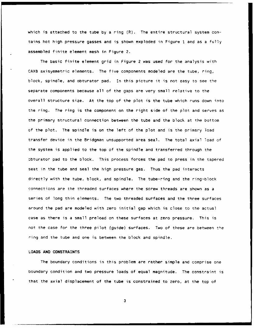
which is attached to the tube by a ring (R). The entire structural system con-
tains hot high pressure gasses and is shown exploded in Figure I and as a fully
assembled finite element mesh in Figure 2.
The basic finite element grid in Figure 2 was used for the analysis with
CAX8 axisymmetric elements. The five components modeled are the tube, ring,
block, spindle, and obturator pad. In this picture it is not easy to see the
separate components because all of the gaps are very small relative to the
overall structure size. At the top of the plot is the tube which runs down into
the ring. The ring is the component on the right side of the plot and serves as
the primary structural connection between the tube and the block at the bottom
of the plot. The spindle is on the left of the plot and is the primary load
transfer device in the Bridgman unsupported area seal. The total axial load of
the system is applied to the top of the spindle and transferred through the
obturator pad to the block. This process forces the pad to press in the tapered
seat in the tube and seal the high pressure gas. Thus the pad interacts
directly with the tube, block, and spindle. The tube-ring and the ring-block
connections are the threaded surfaces where the screw threads are shown as a
series of long thin elements. The two threaded surfaces and the three surfaces
around the pad are modeled with zero initial gap which is close to the actual
case as there is a small preload on these surfaces at zero pressure. This is
not the case for the three pilot (guide) surfaces. Two of these are between the
ring and the tube and one is between the block and spindle.
LOADS AND CONSTRAINTS
The boundary conditions in this problem are rather simple and comprise one
boundary condition and two pressure loads of equal magnitude. The constraint is
that the axial displacement of the tube is constrained to zero, at the top of
3

the picture, to prevent axial movement of the structure. The uniform pressure
loads are defined for the top surface of the spindle and the inside of the tube.
CONTACT SURFACES
The six normal contact surfaces in this structure were modeled using the
ABAQUS three-node interface element (INTER3A). The three pilot surfaces
required only one element each and the initial gap was built into the node point
coordinates. The interfaces between the pad and the other three components
required either three or six elements each. Because these are independent sur-
faces, care was required to insure that they would act independently.
SCREW THREAD SURFACES
One object of this analysis was to demonstrate the contact surface. This
concept was started as the macro-modeling approach of Bretl (ref 6) and has been
expanded here to produce a more detailed model of the surface. The method
starts by replacing the screw threads with an equivalent orthotropic continuum
(the long thin elements) where the orthotropic properties are derived from the
detailed analysis of a single screw thread. This process greatly reduces the
complication of the analysis over any attempt to model individual threads.
While this is a good start, the interface kinematics must also be modeled.
The ABAQUS one-dimensional interface and gap elements (INTER1 and GAPUNI)
are used to model kinematics in the following way. The primary contact surfaces
of the threads are modeled using one-dimensional interface elements to connect
pairs of nodes on the two components. The surface normal for these elements is
defined normal to the contact surface of the thread. This definition is also
required because the two points are at the same point in space i.e., zero gap.
Because the tube threads are to be driven into ring threads by the pressure
4
load, the back surface of the threads is modeled using gap elements where the
initial gap is defined independently from the node position. Here the surface
normal is also defined normal to the contact surface. These kinematic con-
ditions are more important to good results than the equivalent continuum
modeling of the threads.
THREAD FILLET STRESSES
In this analysis the details of the individual threads have been smeared
into an equivalent orthotropic material and a set of kinematic conditions which
define a complex contact surface. The resulting stresses are nominal values
which must be related to the actual thread fillet stresses by a stress con-
centration method (ref 7). This method uses three nominal stresses, the shear
transfer, the radial stress, and the axial stress in the base material. The
shear transfer and radial stresses are the same for each side of the threaded
connection anL are obtained by averaging stresses in the equivalent orthotropic
material of the two components. The axial stresses are different in each com-
ponent and are obtained from elements which use conventional material proper-
ties. The stresses from ABAQUS are output at Gauss stations and all stresses
are taken directly from these data using the closest available Gauss station.
The CAX8 element uses three Gauss stations in the axial direction and each
threaded contact surface has six elements. This combination will give fillet
stress data for 18 positions along each threaded connection. Because the axial
stress is different for each side of each connection, there will be four inde-
pendent plots of fillet stress versus position in this problem. These include a
plot for the internal and external threads on the tube end and the block end of
the system.
• m W |5
RESULTS
This is an extremely complicated problem which can yield many different
results depending on the goals of the analysis. Some highlights of the full
results have been selected and are depicted by the five figures shown. These
consist of a single deformed mesh plot, three stress contour plots, and a single
plot of tensile fillet stress in the thread fillets versus thread position. The
most convenient stress units for this problem are the nondimensionalized
stresses, or stress divided by internal pressure. These will be used in all
cases except the stress contour plots where this is not practical in the ABAQUS
graphic output.
The deformed mesh plot in Figure 3 shows the simple fact that the elastomer
pad is the dominant deformation of the structure. It is so large that many
features are not readily visible in this plot. The first of these is that the
tube expands into the ring which produces an average radial stress of -0.125.
This is in contrast to the radial stress of -0.072 between the ring and the
block. This combination will result in a reduction in the thread fillet
stresses in the tube end when compared with the block end.
Figures 4 through 6 are stress contour plots of the *hree prinrioal
stresses. ABAQUS orders principal stresses in an ascending algebraic order.
This places the high compressive stresses in Figure 4. It is easy to see the
single radial stress contour which runs parallel to the inner surface of the
tube. This contour then runs out and around the high contact stresses at the
pad seal surface. In this case the unsupported area ratio is about 1.60 whi,.h
defines the magnification in pressure between the gas pressure and the seal
pressure.
6
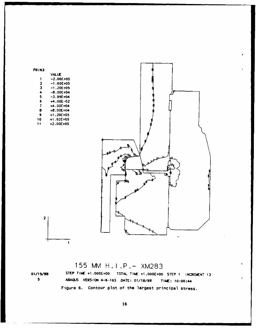
Figure 6 is the stress contour for the largest principal stress and there-
fore shows the high tensile stresses. The only place on this plot which
demonstrates a classic stress concentration is in the inner fillet of the
spindle. The rest of the structure seems to have no high tensile stresses
because the screw thread fillets have been smeared out and do not show.
Figure 7 is the result of the calculation of thread fillet stresses from
stress concentration surfaces. The plot has four independent curves and clearly
shows the highest stresses in the system. The stresses in this plot have been
nondimensionalized to internal pressure and the position starts at the end
nearest the obturator pad seal.
DISCUSSION
This analysis has proven very useful in the definition of strain gage posi-
tions for prototype testing. While the strain gage results have not been for-
mally published, the work was used as an aid in the selection of strain qage
locations and in verification of the results. The initial measured strains did
not correlate with the analysis results and a study was undertaken to discover
the reason for the discrepancy. The problem was in the clearance of the rear
oilot surface between the ring and the tube. The tube was not within drawing
tolerances and was replaced with a correct tube. At that point in time the con-
tact loads on that surface were not accounted for in any design calculations.
A basic objective of any complex structural analysis is to discover the
position of the highest stress in the structure, and what is even more important
is the position of the next highest stress. In this analysis, the highest
stress is clearly in the first internal thread on the block end of the ring.
This position corresponds with the results of fatigue tests on many systems of
the same type. The next highest point is in the first thread on the tube end
7
and this point may indeed crack, but it has never been the point of primary
failure. The high stress concentration in the spindle has shown itself to be a
problem only when there is some material problem. The fatigue test results are
the result of a long history of regular testing, however, the tests are almost
wholly unpublished.
The identification of these high stress concentrations in the thread
fillets actually results in little new information that was not common knowledge
to the engineering community. However, here they have been calculated, from
basic information, in a straightforward way and the solution can be used to
easily generate new design information. In the past, data of this auality were
only available from three-dimensional photoelasticity. This was done for two
full breech systems. One is unpublished and the other (ref 5) is a study of a
more complicated system that includes another component in the load transfer
path. These studies took about one year to complete and provided data for one
oressure and one set of random tolerances. Even with these difficulties, the
study in Reference 6 does validate many trends in the present report. First is
the trend of the tube end fillet stresses being generally lower than the block
end stresses. A second trend, which is validated by photoelasticity, is the
higher stresses in the last threads of the tube.
The last point that should be covered is usefulness of the graphic output
of finite element codes. This seemingly simple function makes an unbelievable
improvement in data transfer to the working engineer. Think of the problems
involved in attempting to obtain a good understanding of this problem from a -r-
strain gages on the available surfaces. Three-dimensional photoelasticty is a
very graphic method, however, the interpretation of the pictures requires some
experience and a great deal of time.
8
CONCLUSIONS
This analysis has demonstrated that this type of complicated structure can be
modeled in a rather simple way and that extremely useful results can be
obtained. The ABAQUS finite element code has been shown to be an outstanding
tool for this type of work. Further, the modeling of threaded connections by
using an equivalent continuum approach seems to be an excellent way to further
reduce model complication. These techniques should prove to be very useful in
the design of screw block systems.
g

REFERENCES
1. Weigle, R. E., Lasselle, R. R., and Purtell, J. P., "Experimental
Investigation of the Fatigue Behavior of Thread-Type Projections,"
Experimental Mechanics, Vol. 3, No. 5, 1963, pp. 105-111.
2. Marino, R. L. and Riley, W. F., "Optimizing Thread-Root Contours Using
Photoelastic Methods," Experimental Mechanics, Vol. 4, No. 1, 1964, pp.
I-!O.
3. Weigle, R. E. and Lasselle, R. R., "Experimental Technique for Predicting
Fatigue Failure of Cannon-Breech Mechanisms," Proceedings of the Society for
Experimental Stress Analysis, Vol. 22, No. 1, 1965, pp. 47-52.
4. ABAQUS Users Manual, Version 4.6, Hibbitt, Karlsson, and Sorensen Inc.,
Providence, RI, 1987.
5. O'Hara, G. P., "Photoelastic Stress Analysis of a High Pressure Breech,"
Watervliet Arsenal Technical Report WTV-7057, Benet Weapons Laboratory,
Watervliet, NY, December 1970.
6. Bretl, J. L., "Finite Element Analysis for General Solids and Threaded
Connections," Ph.D. Thesis, University of Wisconsin-Madison, 1978.
7. O'Hara, G. P., "Stress Concentrations in Screw Threads," ARRADCOM Technical
Report ARLCB-TR-80010, Benet Weapons Laboratory, Watervliet, NY, April 1980.
10

FI 1
Figur 1. Exlddotieo hopnns11

2
155 MM H.K.P.- X28301/19/08 ABAQUS VERSION 4.-6-165 DATE: 01/18/88 T1,C: 09:55:09
Figure 2. Undeformed finite element mesh.
12

UMAG. FACTOR = +1.OE+01
2
155 MM H. I .P.- XM28301/19/80 STEP TIME 41 .0OOE+O0 TOTAL TIME +1 OOOE+O0 STEP i INCREWNT 13
2 ABAQUS VERSION 4-6-165 DATE: 01/18/88 TIME: 10:00:44
Figure 3. Deformed mesh plot.
13

PRI NiVALUE
1 -2. OOE+052 -1 .60E+O53 -1 .20E+054 -8.OOE+045 -3.99E+046 +4.OOE-027 +4.OOE+048 +8.OOE+049 +1 .20E+05
10 +1 .60E+0511 +2.OOE+05
2
155 MM H.I.P.- XM283
01/19/80 STEP TME +1 .OOOE+00 TOTAL TIME +1 .O00E+00 STEP I INCREENT 13
3 ABAUS VERSION 4-6-165 DATE: 01/18/8 TIE: 10:00:4
Figure 4. Contour plot of the smallest principal stress.
14

PR I N12VALUE
1 -2.-OOE+052 -1 .60E+053 -1 .20E+054 -0 .OOE*045 -3.99E+046 +4. OOE--027 +4.OOE+04a +6.00E+-049 +1 .20E+05
10 +1 .60E+0511 +2.OOE*05
155 MM H. I.P.- XM283011986STEP TIkC +11.OOOE+00 TOTAL TINE 4I.00OE+00 STEP 1 INCPE)IENT 13
4 ABAQUS VERSION 4-6-165 DATE: 01/18/88 TI~W: 10:00:44
Figure S. Contour plot of the intermediate principal stress.
ME5E
PR I N3VALUE
1 -2.OOE+052 -1 .60E+053 -1 .20E+054 -8. OOE 045 -3.99E+046 +4. OOE-027 +4. OOE+048 +8.00E+049 +1 .20E+05
10 +1 .60E+0511 +2. OOE+05
2
155 MM H. I.P.- XM28301/19/88 STEP TIME .I.OOOE+O0 TOTAL TIhE +1 .OOOE+O0 STEP I INCREMENT 13
5 ABAQIJS VERSION 4-6-165 DATE: 01/18/88 TIME: 10:00:44
Figure 6. Contour plot of the largest principal stress.
16

II
C\.\I CID
- 430
LL
-CU
CQ C.2 43-F
4"" J
I-
,/ / '- 5 3
t / - 4-
2m .3 W ,
2- \ \>/ 4-
-"/ "S7 1111A
17I
-~ I (I
- I
-- 'IIlIII II I llllI I II II

TECHNICAL REPORT INTERNAL DISTRIBUTION LIST
NO. OFCOPIES
CHIEF, DEVELOPMENT ENGINEERING DIVISIONATTN: SMCAR-CCB-D I
-DA 1-DC 1-DM 1-DP 1-DR 1-DS (SYSTEMS) 1
CHIEF, ENGINEERING SUPPORT DIVISIONATTN: SMCAR-CCB-S I
-SE I
CHIEF, RESEARCH DIVISION-ATTN: SMCAR-CCB-R 2
-RA 1-RM 1-RP 1-RT 1
TECHNICAL LIBRARY 5ATTN: SMCAR-CCB-TL
TECHNICAL PUBLICATIONS & EDITING SECTION 3ATTN: SMCAR-CCB-TL
DIRECTOR, OPERATIONS DIRECTORATE 1ATTN: SMCWV-OD
DIRECTOR, PROCUREMENT DIRECTORATE IATTN: SMCWV-PP
DIRECTOR, PRODUCT ASSURANCE DIRECTORATE IATTN: SMCWV-QA
NOTE: PLEASE NOTIFY DIRECTOR, BENET LABORATORIES, ATTN: SMCAR-CCB-TL, OFANY ADDRESS CHANGES.

TECHNICAL REPORT EXTERNAL DISTRIBUTION LIST
NO. OF NO. OF
COPIES COPIES
ASST SEC OF THE ARMY COMMANDERRESEARCH AND DEVELOPMENT ROCK ISLAND ARSENALATTN: DEPT FOR SCI AND TECH ATTN: SMCRI-ENMTHE PENTAGON ROCK ISLAND, IL 61299-5000WASHINGTON, D.C. 20310-0103
DIRECTORADMINISTRATOR US ARMY INDUbTRIAL BASE ENGR ACTVDEFENSE TECHNICAL INFO CENTER ATTN: AMXIB-PATTN: DTIC-FDAC 12 ROCK ISLAND, IL 61299-7260CAMERON STATIONALEXANDRIA, VA 22304-6145 COMMANDER
US ARMY TANK-AUTMV R&D COMMANDCOMMANDER ATTN: AMSTA-DDL (TECH LIB)US ARMY ARDEC WARREN, MI 48397-5000ATTN: SMCAR-AEE 1
SMCAR-AES, BLDG. 321 1 COMMANDERSMCAR-AET-O, BLDG. 351N 1 US MILITARY ACADEMYSMCAR-CC 1 ATTN: DEPARTMENT OF MECHANICSSMCAR-CCP-A 1 WEST POINT, NY 10996-1792SMCAR-FSA 1SMCAR-FSM-E 1 US ARMY MISSILE COMMANDSMCAR-FSS-D, BLDG. 94 1 REDSTONE SCIENTIFIC INFO CTR 2SMCAR-IMI-I (STINFO) BLDG. 59 2 ATTN: DOCUMENTS SECT, BLDG. 4484
PICATINNY ARSENAL, NJ 07806-5000 REDSTONE ARSENAL, AL 35898-5241
DIRECTOR COMMANDERUS ARMY BALLISTIC RESEARCH LABORATORY US ARMY FGN SCIENCE AND TECH CTRATTN: SLCBR-DD-T, BLDG. 305 1 ATTN: DRXST-SDABERDEEN PROVING GROUND, MD 21005-5066 220 7TH STREET, N.E.
CHARLOTTESVILLE, VA 22901DIRECTORUS ARMY MATERIEL SYSTEMS ANALYSIS ACTV COMMANDERATTN: AMXSY-MP 1 US ARMY LABCOMABERDEEN PROVING GROUND, MD 21005-5071 MATERIALS TECHNOLOGY LAB
ATTN: SLCMT-IML (TECH LIB) 2COMMANDER WATERTOWN, MA 02172-0001HQ, AMCCOMATTN: AMSMC-IMP-L 1ROCK ISLAND, IL 61299-6000
NOTE: PLEASE NOTIFY COMMANDER, ARMAMENT RESEARCH, DEVELOPMENT, AND ENGINEERINGCENTER, US ARMY AMCCOM, ATTN: BENET LABORATORIES, SMCAR-CCB-TL,WATERVLIET, NY 12189-4050, OF ANY ADDRESS CHANGES.

TECHNICAL REPORT EXTERNAL DISTRIBUTION LIST (CONT'D)
NO. OF NO. OFCOPIES COPIES
COMMANDER COMMANDERUS ARMY LABCOM, ISA AIR FORCE ARMAMENT LABORATORY
ATTN: SLCIS-IM-TL 1 ATTN: AFATL/MN2800 POWDER MILL ROAD EGLIN AFB, FL 32542-5434ADELPHI, MD 20783-1145
COMMANDERCOMMANDER AIR FORCE ARMAMENT LABORATORYUS ARMY RESEARCH OFFICE ATTN: AFATL/MNFATTN: CHIEF, IPO I EGLIN AFB, FL 32542-5434P.O. BOX 12211RESEARCH TRIANGLE PARK, NC 27709-2211 METALS AND CERAMICS INFO CTR
BATTELLE COLUMBUS DIVISION
DIRECTOR 505 KING AVENUEUS NAVAL RESEARCH LAB COLUMBUS, OH 43201-2693ATTN: MATERIALS SCI & TECH DIVISION 1
CODE 26-27 (DOC LIB) 1WASHINGTON, D.C. 20375
NOTE: PLEASE NOTIFY COMMANOER, ARMAMENT RESEARCH, DEVELOPMENT, AND ENGINEERINGCENTER, US ARMY AMCCOM, ATTN: BENET LABORATORIES, SMCAR-CCB-TL,WATERVLIET, NY 12189-4050, OF ANY ADDRESS CHANGES.