Embed Size (px)
Citation preview

These instructions are to be used with the following Jandy Pro Series LXi Spare Parts:R0454700-- Burner Assembly Replacement Kit, Pool/Spa Heater Model LXi R0454701-- Burner Assembly with Pressure Tap Replacement Kit, Pool/Spa Heater Model LXiR0454803-- Natural Gas Manifold Assembly Replacement Kit, Pool/Spa Heater Model 250 LXiR0454804-- Natural Gas Manifold Assembly Replacement Kit, Pool/Spa Heater Model 300 LXiR0454805-- Natural Gas Manifold Assembly Replacement Kit, Pool/Spa Heater Model 400 LXiR0455003-- LP Gas Manifold Assembly Replacement Kit, Pool/Spa Heater Model 250 LXiR0455004-- LP Gas Manifold Assembly Replacement Kit, Pool/Spa Heater Model 300 LXiR0455005-- LP Gas Manifold Assembly Replacement Kit, Pool/Spa Heater Model 400 LXiR0457500-- Igniter Replacement Kit, Pool/Spa Heater Model LXiR0458600-- Flame Sensor Rod Replacement, Pool/Spa Heater Model LXi
This document gives instructions for replacing the Igniter, Flame Sensor, Burner, and Gas Manifold Assembly in all Jandy LXi™ model pool/spa heaters. The instructions must be followed exactly. These instructions were written with safety as the priority.
Not following the written procedure or taking short cuts may increase the risk of personal injury. Read through the instructions completely before starting the procedure.
Before starting the procedure, use the parts list at the back of these instructions to identify the parts that are in your kit. If any parts are missing from the kit, please call your local distributor for assistance. For technical assistance, please contact our Technical Support Department at (800) 822-7933.
A. Disassembly
WARNINGSHOCK HAZARD!
Turn off all switches and the main breaker in the pool/spa heater electrical circuit before starting the re-placement procedure. Failure to comply may cause a shock hazard resulting in severe personal injury or death.
1. Turn off the electrical power to the heater. Turn off the main gas supply to the heater at the meter or the manual gas cock outside the heater.
2. Remove the front panel (door).
3. Turn the gas valve control knob to OFF.
H029
4900
Rev
B
WARNINGFOR YOUR SAFETY: This product must be installed and serviced by a contractor who is licensed and qualified in pool equipment by the jurisdiction in which the product will be installed where such state or local requirements exists. In the event no such state or local requirement exists, the installer or maintainer must be a professional with sufficient experience in pool equipment installation and maintenance so that all of the instructions in this manual can be followed exactly. Before installing this product, read and follow all warning notices and instructions that accompany this product. Failure to follow warning notices and instructions may result in property damage, personal injury, or death. Improper installation and/or operation can create carbon monoxide gas and flue gases which can cause serious injury, property damage, or death. For indoor installations, as an additional measure of safety, Zodiac Pool Systems, Inc. strongly recommends installation of suitable Carbon Monoxide detectors in the vicinity of this appliance and in any adjacent occupied spaces. Improper installation and/or operation will void the warranty.
Jandy Pro Series LXi™ Igniter, Flame Sensor, Burner, and
Manifold Assembly Spare Parts
WARNINGIf the information in these instructions is not followed exactly, a fire or explosion may result causing property damage, personal injury or loss of life.
Page 2 Jandy® Pro Series LXiTM Spare Parts | Zodiac®
4. Remove the hex head screws (10 screws on 250 and 300 models; 11 screws on 400 model) that hold the air box cover to the air box. Remove the air box cover.
B. Replacing the Igniter1. Follow steps 1 through 4 of Section A.2. Remove the two (2) nuts, located on the front
burner panel, that secure the igniter in place. See Figure 1.
3. Clean any remaining debris from the gasket off the front of the front burner panel.
4. Remove the new igniter (see Figure 6) from its protective packaging and remove the igniter mounting nuts from the manila envelope included in the kit.
5. Place a new gasket over the two (2) studs on the burner panel.
6. Carefully slide the new igniter into the burner panel and align the holes in the igniter to the studs on the front of the burner panel.
7. Secure the igniter using two (2) new nuts.8. Connect the igniter wires.9. Confirm that the wiring is correct. See Figure 8.10. Follow steps 1 through 4 of Section F to complete
reassembly.
C. Replacing the Flame Sensor1. Follow steps 1 through 4 of Section A.2. Remove the hex head screw located on the sensor
bracket holding the sensor to the burner panel.3. Remove the sensor from the burner panel.4. Disconnect the sensor wire.
5. Remove the sensor (see Figure 7) from the protective packaging and remove the sensor mounting screw from the manila envelope in the kit.
6. Slide the new sensor into the burner panel. Align the sensor mounting hole to the burner panel sensor mounting hole.
7. Secure the sensor using the screw provided.8. Reconnect the sensor wire. Confirm that the wiring
is correct. See Figure 8.9. Follow steps 1 through 4 of Section F to complete
reassembly.
D. Replacing a Burner1. Follow steps 1 through 4 of Section A.2. Remove the two (2) hex head screws that hold
the manifold bracket to the air box. Remove the bracket.
3. Disconnect the gas supply pipe from the gas valve and remove it from the heater. Disconnect the yellow and brown wires from the gas valve.
4. Remove the four (4) hex head screws that hold the manifold to the burner panel. Remove the manifold.
5. Remove the four (4) hex head screws that hold the burner to the burner panel. Remove the burner from the burner panel.
NOTE If removing a burner with a pressure tap, be sure to replace it with a burner with a tap.
6. Remove the gasket from the burner panel by cutting it with a razor or knife.
7. Install a new gasket, from the kit, on the burner panel.
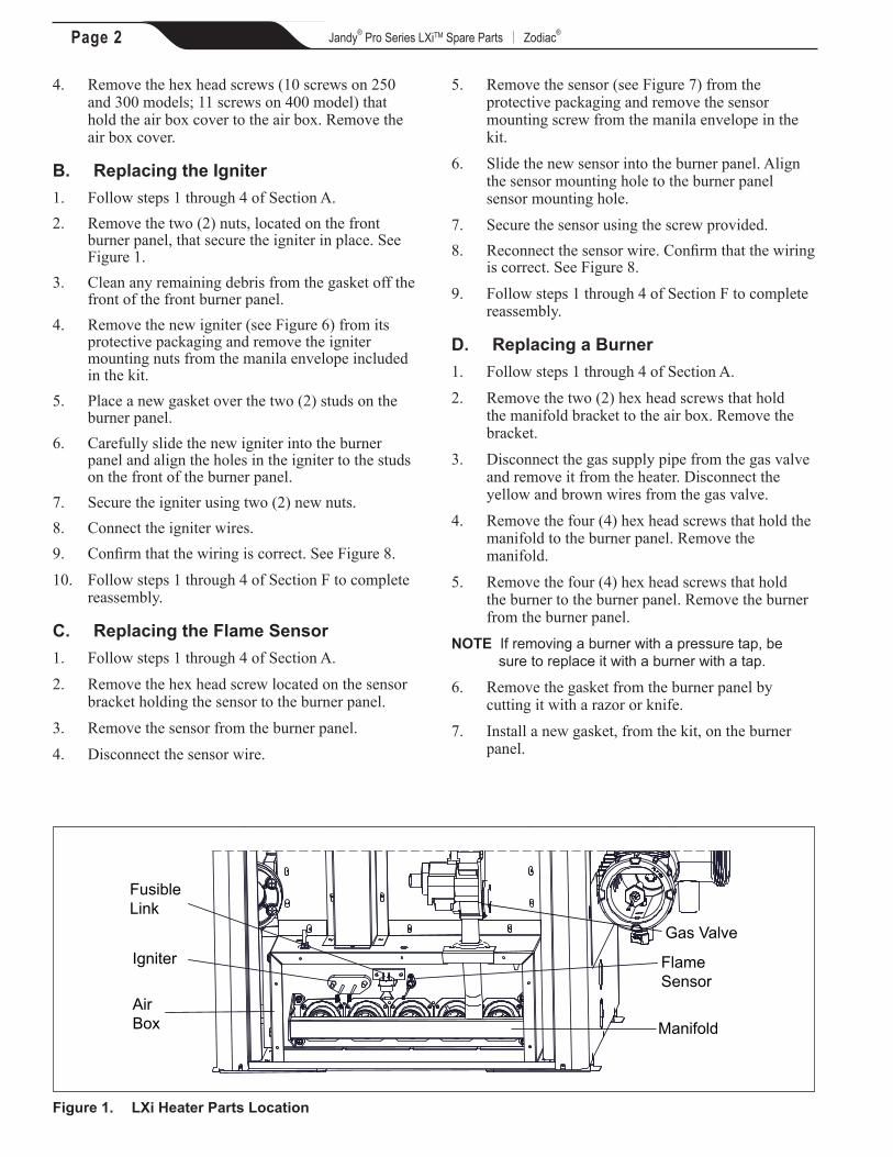
Flame Sensor
FusibleLink
Igniter
AirBox Manifold
Gas Valve
Figure 1. LXi Heater Parts Location
Page 3Jandy® Pro Series LXiTM Spare Parts | Zodiac®
8. Position burners, ensuring that the ports are aligned, then slide into the holes of the burner panel. Make sure the burner slots are facing up on top of the burner. Securely fasten the burner to the burner panel with four (4) screws.
9. Align and place the manifold orifices into the burner orifice hole, while ensuring that the gas orifices are centered in the burner panel holes.
10. Once the alignment between the manifold and the burner is complete, secure the manifold to the burner panel using four (4) screws.
11. Place the manifold bracket onto the air box and manifold inlet pipe and secure with two (2) hex head screws.
12. Connect the brown and yellow wires to the gas valve.
13. Place the manifold gasket over the manifold inlet pipe and slide it between the air box cutout and the manifold bracket cutout.
14. Reconnect the gas supply line to the gas valve. Turn on the main gas supply and check the connections for leaks.
CAUTIONSome leak test solutions (including soap and water) may cause corrosion or stress cracking. Rinse the piping with water after testing.
WARNINGNever test for gas leaks with an open flame. Always use a test leak solution or liquid soap solution to check for gas leaks at connections.
15. Confirm the wiring is correct. See Figure 8.16. Follow steps 1 through 4 of Section F to complete
reassembly.
E. Replacing the Manifold Assembly1 Follow steps 1 through 4 of Section A.2. Remove the two (2) hex head screws that hold
the manifold bracket to the air box. Remove the bracket.
3. Remove the wires (brown and yellow) from the gas valve.
4. Disconnect the gas supply pipe from the gas valve and remove it from the heater.
5. Remove the four (4) hex head screws that hold the manifold to the burner panel. Remove the manifold assembly.
6. Remove the gas valve and street elbow from the gas manifold.
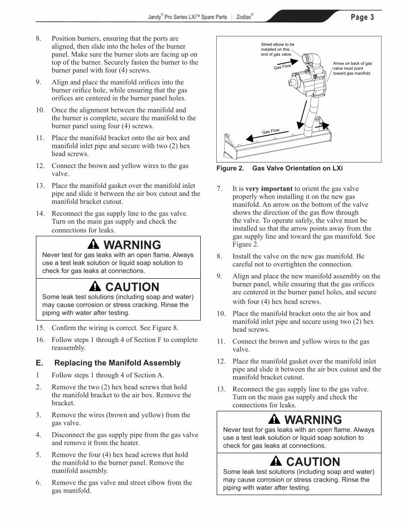
7. It is very important to orient the gas valve properly when installing it on the new gas manifold. An arrow on the bottom of the valve shows the direction of the gas flow through the valve. To operate safely, the valve must be installed so that the arrow points away from the gas supply line and toward the gas manifold. See Figure 2.
8. Install the valve on the new gas manifold. Be careful not to overtighten the connection.
9. Align and place the new manifold assembly on the burner panel, while ensuring that the gas orifices are centered in the burner panel holes, and secure with four (4) hex head screws.
10. Place the manifold bracket onto the air box and manifold inlet pipe and secure using two (2) hex head screws.
11. Connect the brown and yellow wires to the gas valve.
12. Place the manifold gasket over the manifold inlet pipe and slide it between the air box cutout and the manifold bracket cutout.
13. Reconnect the gas supply line to the gas valve. Turn on the main gas supply and check the connections for leaks.
CAUTIONSome leak test solutions (including soap and water) may cause corrosion or stress cracking. Rinse the piping with water after testing.
WARNINGNever test for gas leaks with an open flame. Always use a test leak solution or liquid soap solution to check for gas leaks at connections.
Figure 2. Gas Valve Orientation on LXi
Street elbow to be installed on this end of gas valve.
Arrow on back of gas valve must point toward gas manifold.
Gas Flow
Gas Flow
Page 4 Jandy® Pro Series LXiTM Spare Parts | Zodiac®
14. Confirm that the wiring is correct. See Figure 8.15. Turn the gas control knob to ON.16. Follow steps 1 through 4 of Section F to complete
reassembly.
F. Reassembly1. Remove and replace the gasket on the air box
cover.2. Align the air box cover with the air box. Secure
with hex head screws (10 screws on 250 and 300 models; 11 screws on 400 model).
3. Check the manifold pressure with the heater running. Be sure to refer to the rating plate on the heater or the Installation and Operation manual that came with your heater to determine the correct manifold pressure for your model. For information on proper procedures for checking manifold pressure, refer to the "Professional Maintenance and Service" section of the Installation and Operation manual.
4. Reinstall the front panel door of the heater and turn on the electrical supply to the heater. Test the heater for proper ignition and operation.
Page 5Jandy® Pro Series LXiTM Spare Parts | Zodiac®
Parts List for Spare Parts
Description
R04
5470
0
R04
5470
1
R04
5480
3
R04
5480
4
R04
5480
5
R04
5500
3
R04
5500
4
R04
5500
5
R04
5750
0
R04
5860
0
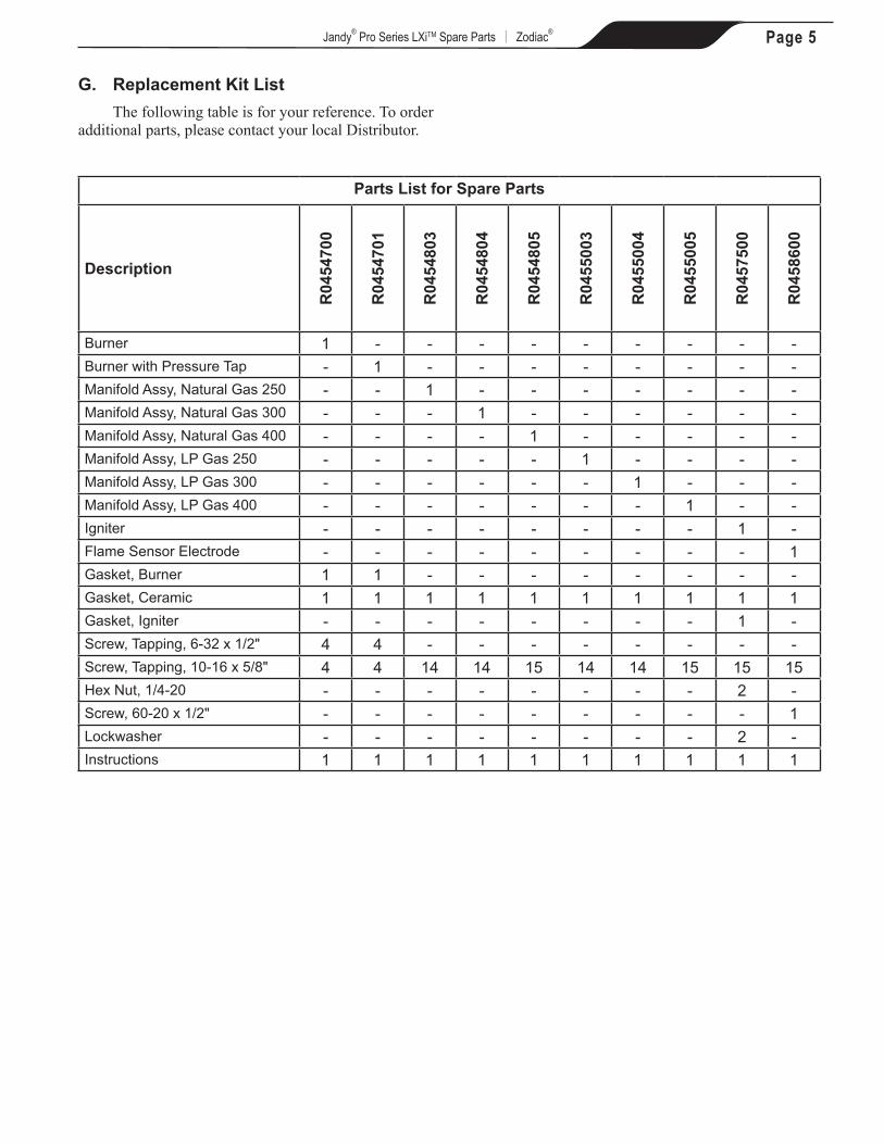
Burner 1 - - - - - - - - -Burner with Pressure Tap - 1 - - - - - - - -Manifold Assy, Natural Gas 250 - - 1 - - - - - - -Manifold Assy, Natural Gas 300 - - - 1 - - - - - -Manifold Assy, Natural Gas 400 - - - - 1 - - - - -Manifold Assy, LP Gas 250 - - - - - 1 - - - -Manifold Assy, LP Gas 300 - - - - - - 1 - - -Manifold Assy, LP Gas 400 - - - - - - - 1 - -Igniter - - - - - - - - 1 -Flame Sensor Electrode - - - - - - - - - 1Gasket, Burner 1 1 - - - - - - - -Gasket, Ceramic 1 1 1 1 1 1 1 1 1 1Gasket, Igniter - - - - - - - - 1 -Screw, Tapping, 6-32 x 1/2" 4 4 - - - - - - - -Screw, Tapping, 10-16 x 5/8" 4 4 14 14 15 14 14 15 15 15Hex Nut, 1/4-20 - - - - - - - - 2 -Screw, 60-20 x 1/2" - - - - - - - - - 1Lockwasher - - - - - - - - 2 -Instructions 1 1 1 1 1 1 1 1 1 1
G. Replacement Kit ListThe following table is for your reference. To order
additional parts, please contact your local Distributor.
Page 6 Jandy® Pro Series LXiTM Spare Parts | Zodiac®
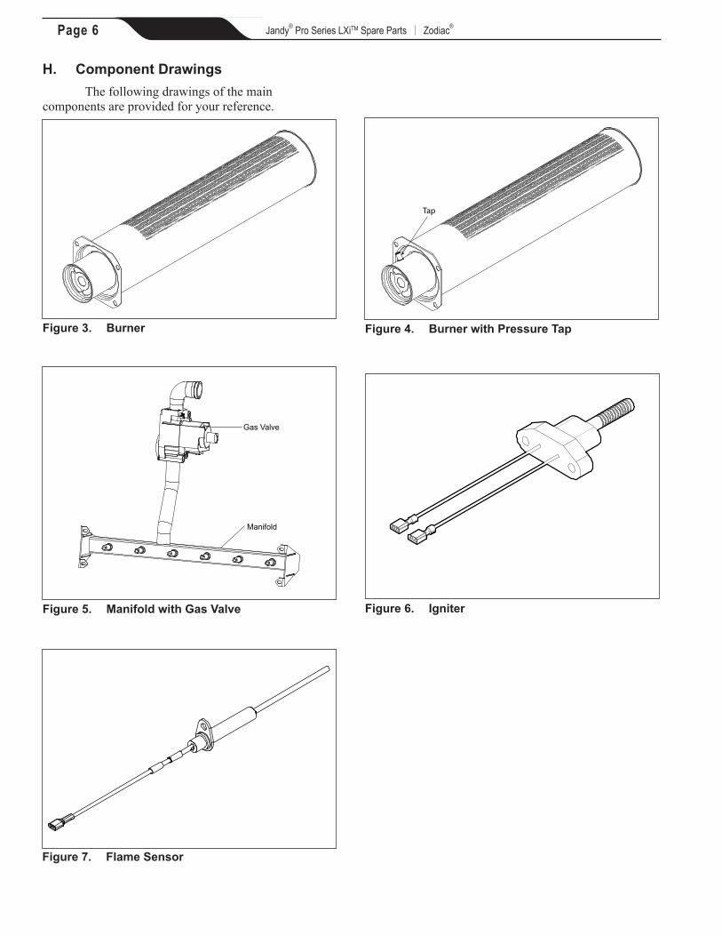
H. Component Drawings The following drawings of the main
components are provided for your reference.
Figure 3. Burner
Tap
Figure 4. Burner with Pressure Tap
Gas Valve
Manifold
Figure 5. Manifold with Gas Valve Figure 6. Igniter
Figure 7. Flame Sensor
Page 7Jandy® Pro Series LXiTM Spare Parts | Zodiac®
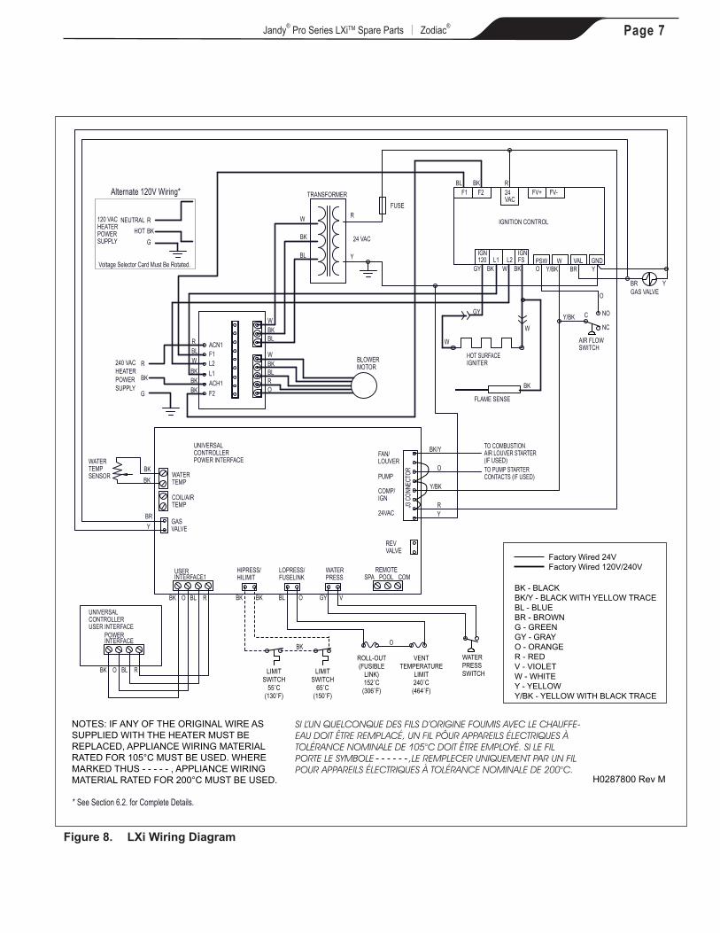
Figure 8. LXi Wiring Diagram
L1
F1ACN1
ACH1
L2
F2G
R
BK
240 VACHEATERPOWERSUPPLY
BLOWERMOTOR
WBKBLRO
IGNITION CONTROL
F1 F2 24VAC
FV+ FV-
IGN120 L1 L2
IGNFS W GNDVAL
BK
W
BK
BL R
GY BK
24 VAC
R
Y
HOT SURFACE IGNITER
W
GY
W
FLAME SENSE
TRANSFORMER
BK
WATERTEMP
GASVALVE
USER INTERFACE1
BK O BL R
HIPRESS/HILIMIT
LOPRESS/FUSELINK
WATERPRESS
REMOTESPA POOL COM
REVVALVE
24VAC
PUMP
COMP/IGN
FAN/LOUVER
UNIVERSAL CONTROLLERPOWER INTERFACE
UNIVERSAL CONTROLLERUSER INTERFACE
POWER INTERFACE
BK O BL R
AIR FLOWSWITCH
GAS VALVE
WATERTEMPSENSOR
BL
W
BK
TO PUMP STARTERCONTACTS (IF USED)
TO COMBUSTION AIR LOUVER STARTER (IF USED)
W
FUSE
RY
O
BK/Y
O
Y/BKO BR Y
BR Y
RBL
BKBKBK
WBKBL
BRY
BK BK
BK
BL O VGY
BKBK
PSW
Y/BK
C NO
NCY/BK
COIL/AIRTEMP
O
J3 C
ONNE
CTOR
Factory Wired 24V Factory Wired 120V/240V
BK - BLACKBK/Y - BLACK WITH YELLOW TRACE BL - BLUEBR - BROWNG - GREENGY - GRAYO - ORANGER - REDV - VIOLETW - WHITEY - YELLOWY/BK - YELLOW WITH BLACK TRACE
H0287800 Rev M
- - - - - -
* See Section 6.2. for Complete Details.
NOTES: IF ANY OF THE ORIGINAL WIRE AS SUPPLIED WITH THE HEATER MUST BE REPLACED, APPLIANCE WIRING MATERIAL RATED FOR 105°C MUST BE USED. WHERE MARKED THUS - - - - - , APPLIANCE WIRING MATERIAL RATED FOR 200°C MUST BE USED.
120 VACHEATERPOWERSUPPLY
Alternate 120V Wiring*
G
RBK
NEUTRALHOT
Voltage Selector Card Must Be Rotated.
LIMITSWITCH
55˚C(130˚F)
LIMITSWITCH
65˚C(150˚F)
ROLL-OUT(FUSIBLE
LINK)152˚C(306˚F)
WATERPRESSSWITCH
VENTTEMPERATURE
LIMIT240˚C(464˚F)

Zodiac Pool Systems Canada, Inc. 2115 South Service Road West, Unit 3 Oakville, Ontario • Canada L6L 5W2 1.888.647.4004 | www.zodiacpoolsystems.ca
ZODIAC® is a registered trademark of Zodiac International, S.A.S.U., used under license.All trademarks referenced herein are the property of their respective owners.
©2012 Zodiac Pool Systems, Inc. H0294900 Rev B 1209
Page 8Jandy® Pro Series LXiTM Spare Parts | Zodiac®
Zodiac Pool Systems, Inc. 2620 Commerce Way, Vista, CA 92081 1.800.822.7933 | www.ZodiacPoolSystems.com