Embed Size (px)
Citation preview

James Welch
October 30, 20071
FEL Commissioning PlansFEL Commissioning PlansJ. Welch, et. al.J. Welch, et. al.
Accelerator System Breakout Session
10/30/07
LCLSLCLS
James Welch
October 30, 20072
Linac/BC2
FEE/NEH/X-Ray Tunnel/FEH Installation
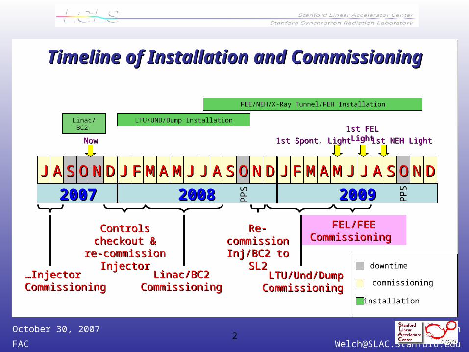
Timeline of Installation and CommissioningTimeline of Installation and Commissioning
JJ AA SS OO NN DD JJ FF MM AA MM JJ JJ AA SS OO NN DD JJ FF MM AA MM JJ JJ
Linac/BC2 Linac/BC2 Commissioning Commissioning
20072007 20082008
LTU/Und/Dump LTU/Und/Dump Commissioning Commissioning
AA SS OONN DD
20092009PPS
PPS
Controls Controls checkout & re-checkout & re-
commission commission InjectorInjector
Re-Re-commission commission
Inj/BC2 to SL2Inj/BC2 to SL2
FEL/FEE FEL/FEE Commissioning Commissioning
……InjectorInjectorCommissioning Commissioning
NowNow
PPS
PPS
1st Spont. Light1st Spont. Light 1st NEH Light1st NEH Light
downtime
commissioning
LTU/UND/Dump Installation
1st FEL1st FELLightLight
installation
James Welch
October 30, 20073
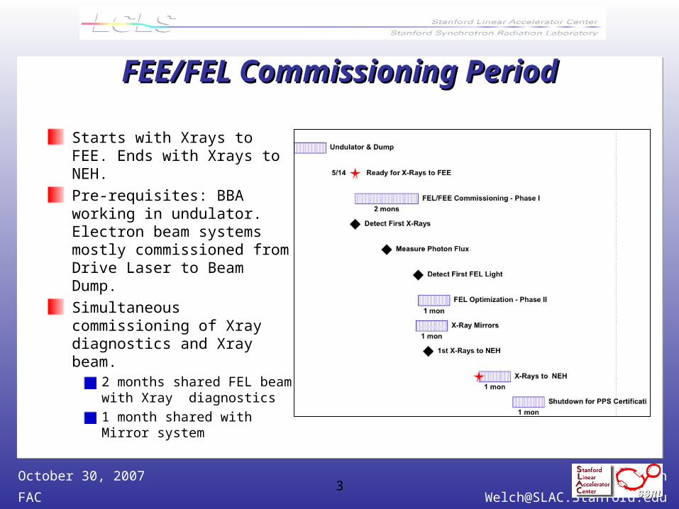
FEE/FEL Commissioning PeriodFEE/FEL Commissioning Period
Starts with Xrays to FEE. Ends with Xrays to NEH.
Pre-requisites: BBA working in undulator. Electron beam systems mostly commissioned from Drive Laser to Beam Dump.
Simultaneous commissioning of Xray diagnostics and Xray beam.
2 months shared FEL beam with Xray diagnostics
1 month shared with Mirror system
James Welch
October 30, 20074
FEL Commissioning - Phase I FEL Commissioning - Phase I (~2 months)(~2 months)
Using SR onlyGet “First Light” milestone
Establish optical axis
Commission X ray diagnostics
Characterize SR from individual and multiple segments
Measure “photon flux” milestone

James Welch
October 30, 20075
X Ray Diagnostics X Ray Diagnostics
SolidAttenuator
Gas Attenuator
Slit
Start of Experimental
Hutches
5 mm diameter
collimators
Muon Shield
Hard X-Ray Offset mirror
system
TotalEnergyThermal Detector
WFOV
NFOV
Gas Detector
Gas Detector
e-
Direct Imager
Hard x-ray Monochromator (K Spectrometer)
Soft X-ray
Imager
Soft X-Ray Offset mirror
system
James Welch
October 30, 20076
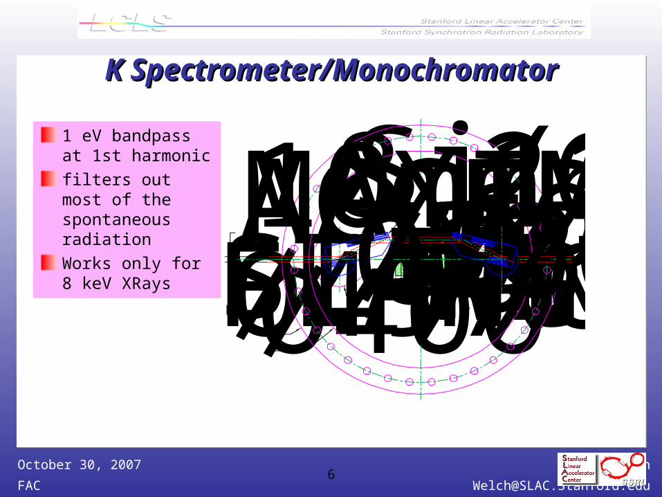
K Spectrometer/MonochromatorK Spectrometer/Monochromator
1 eV bandpass at 1st harmonic
filters out most of the spontaneous radiation
Works only for 8 keV XRays 801060
Ø400Ø497 [Ø19.6]8.265 KEV SETTING
STANDARD WIRE-SEALFLANGE FOR Ø16" TUBETUNGSTEN BEAM STOPWITH B4C PROTECTION FACESi(111) 10mmMAXIMUMACCEPTANCE117
28Ø100
James Welch
October 30, 20077
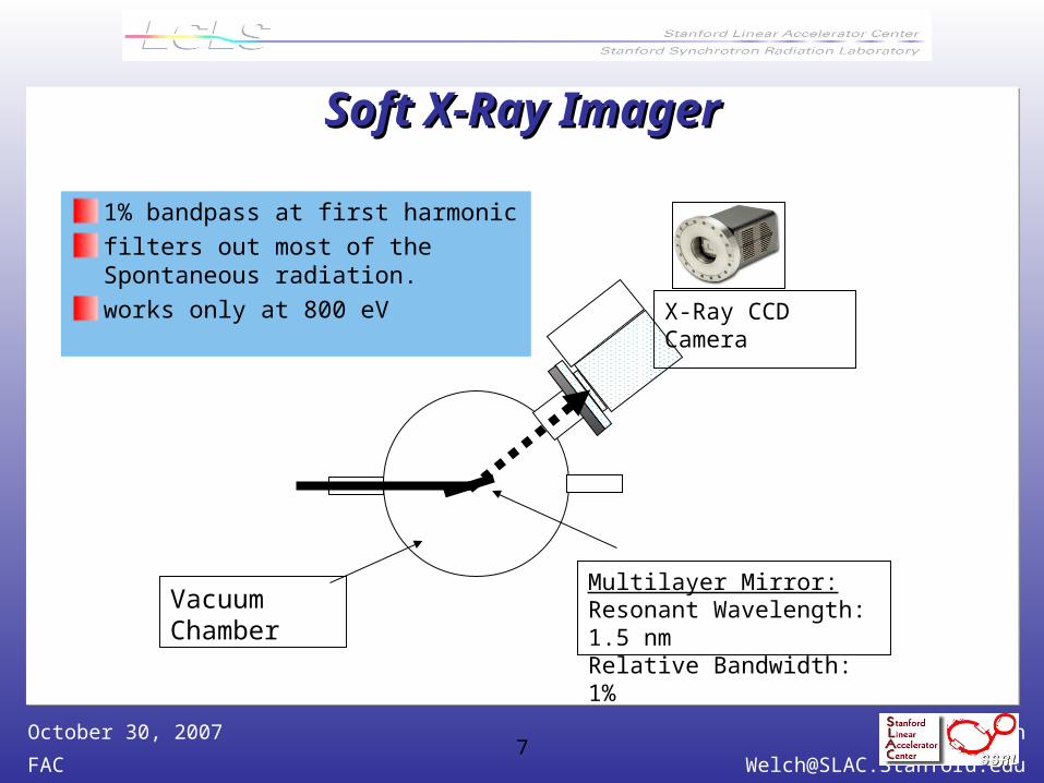
Soft X-Ray ImagerSoft X-Ray Imager
1% bandpass at first harmonic
filters out most of the Spontaneous radiation.
works only at 800 eV
Multilayer Mirror:Resonant Wavelength: 1.5 nmRelative Bandwidth: 1%
Vacuum Chamber
X-Ray CCD Camera
James Welch
October 30, 20078
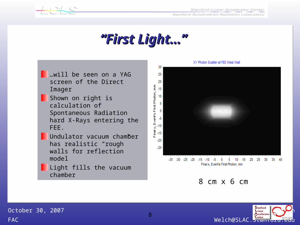
““First Light…” First Light…”
…will be seen on a YAG screen of the Direct Imager
Shown on right is calculation of Spontaneous Radiation hard X-Rays entering the FEE.
Undulator vacuum chamber has realistic “rough” walls for reflection model
Light fills the vacuum chamber
8 cm x 6 cm
James Welch
October 30, 20079
Establish Optical AxisEstablish Optical Axis
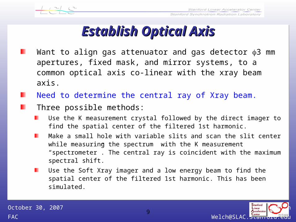
Want to align gas attenuator and gas detector 3 mm apertures, fixed mask, and mirror systems, to a common optical axis co-linear with the xray beam axis.
Need to determine the central ray of Xray beam.
Three possible methods:Use the K measurement crystal followed by the direct imager to find the spatial center of the filtered 1st harmonic.
Make a small hole with variable slits and scan the slit center while measuring the spectrum with the K measurement “spectrometer”. The central ray is coincident with the maximum spectral shift.
Use the Soft Xray imager and a low energy beam to find the spatial center of the filtered 1st harmonic. This has been simulated.
James Welch
October 30, 200710
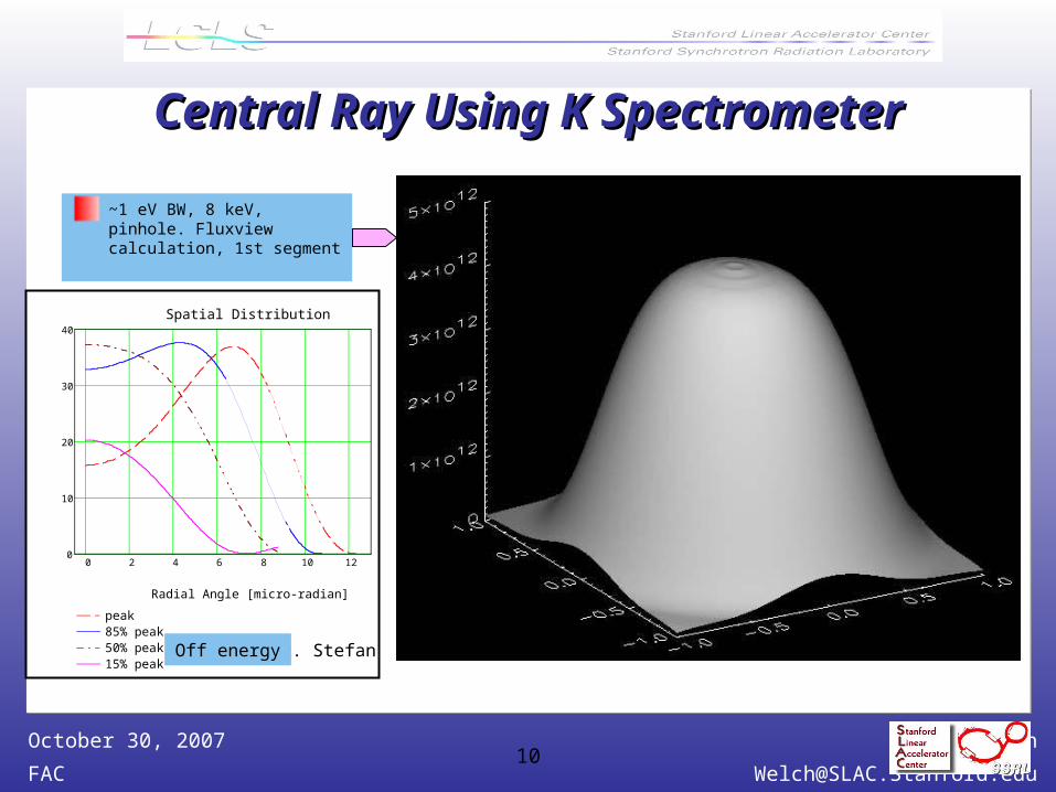
Central Ray Using K SpectrometerCentral Ray Using K Spectrometer
~1 eV BW, 8 keV, pinhole. Fluxview calculation, 1st segment
0 2 4 6 8 10 120
10
20
30
40
peak85% peak50% peak15% peak
Spatial Distribution
Radial Angle [micro-radian]
Photon Flux [photons/100 um^2/pulse]
P. StefanOff energy
James Welch
October 30, 200711
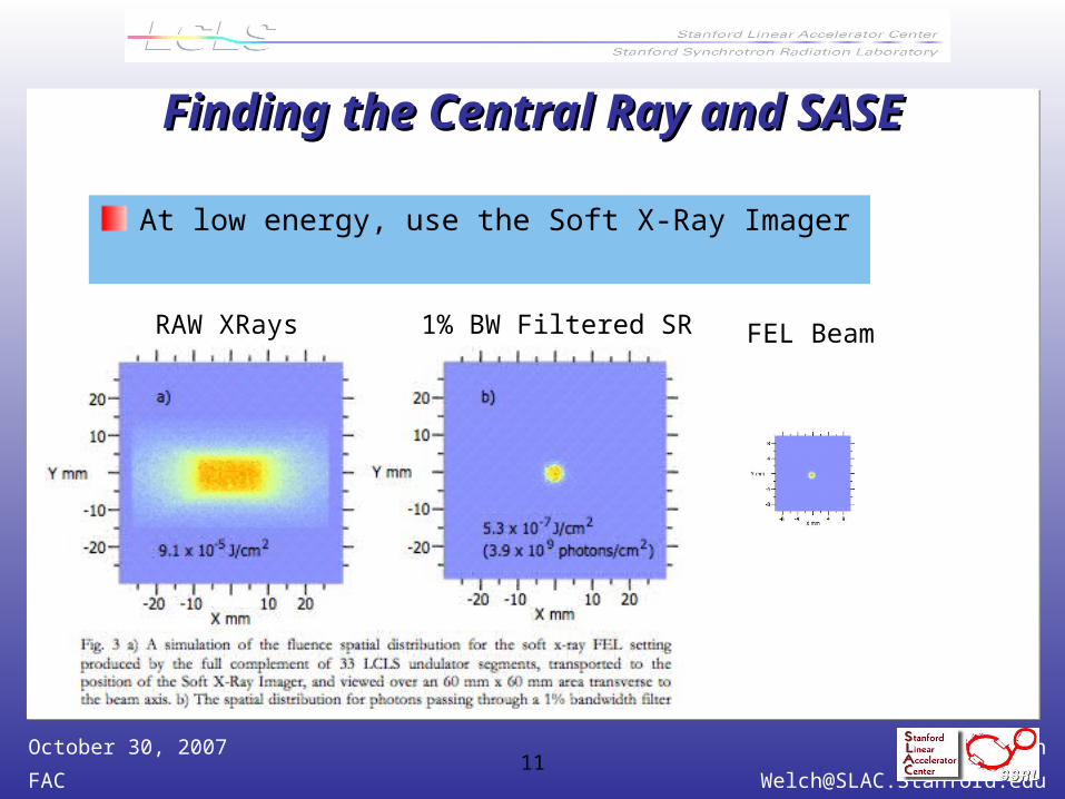
Finding the Central Ray and SASEFinding the Central Ray and SASE
At low energy, use the Soft X-Ray Imager
FEL Beam1% BW Filtered SRRAW XRays
James Welch
October 30, 200712
Measure SR from Undulator SegmentsMeasure SR from Undulator Segments
Measure what? Central ray position, as above, and relate it to local BPM readings.
Average spectrum using K monochromator
Spatial profile, using the Direct Imager.
K measurement? Will we have time?
Why?Provides a basis for future comparisons. Establishes all segments are producing Xrays as expected and are free from
anomolies.
James Welch
October 30, 200713
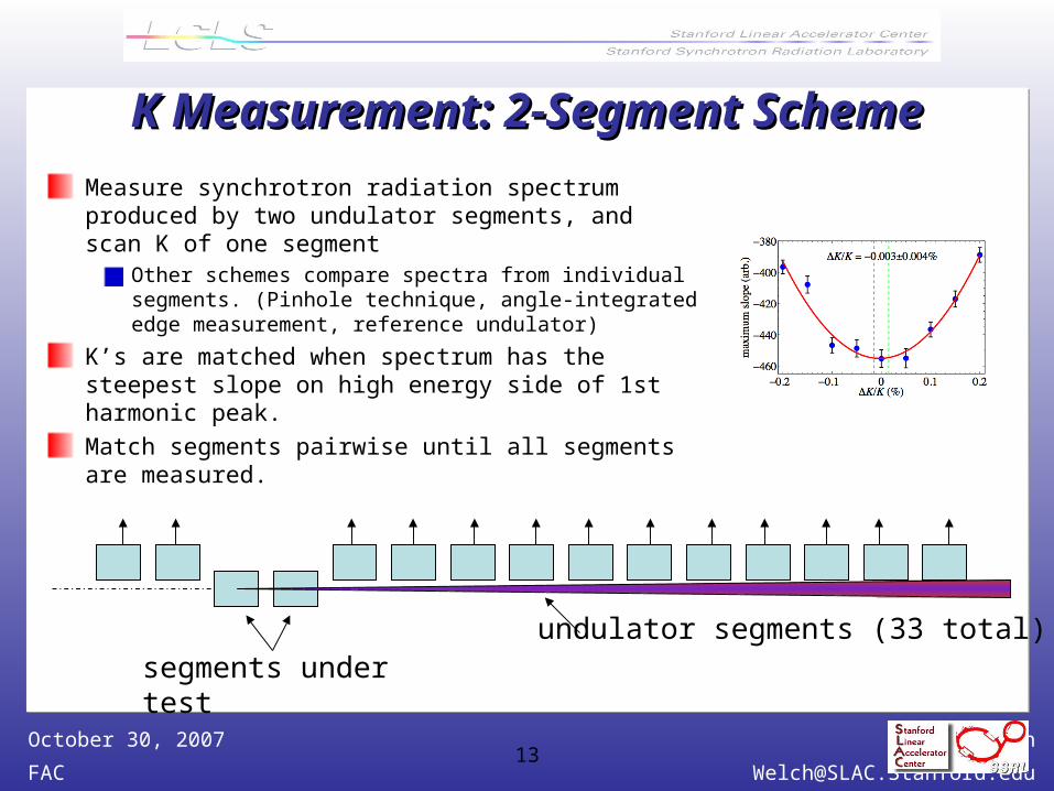
K Measurement: 2-Segment SchemeK Measurement: 2-Segment Scheme
Measure synchrotron radiation spectrum produced by two undulator segments, and scan K of one segment
Other schemes compare spectra from individual segments. (Pinhole technique, angle-integrated edge measurement, reference undulator)
K’s are matched when spectrum has the steepest slope on high energy side of 1st harmonic peak.
Match segments pairwise until all segments are measured.
undulator segments (33 total)segments under test

James Welch
October 30, 200714
FEL Commissioning - Phase II FEL Commissioning - Phase II (1 month) (1 month)
Generate and detect FEL Radiation at low energyFind SASE signal
Measure Gain Curves
Optimize gain
Steer FEL Radiation thru center of C1 5 mm aperture, then M1-Soft
Change energies when time allows
James Welch
October 30, 200715
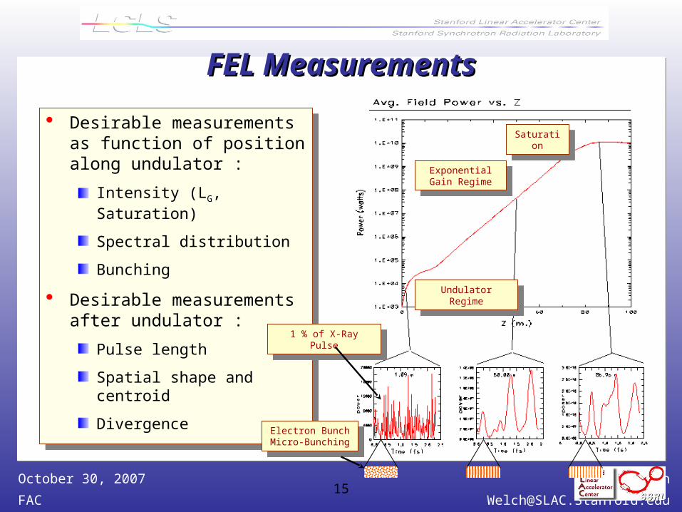
Desirable measurements as function of position along undulator :
Intensity (LG, Saturation)
Spectral distribution
Bunching
Desirable measurements after undulator :
Pulse length
Spatial shape and centroid
Divergence
Desirable measurements as function of position along undulator :
Intensity (LG, Saturation)
Spectral distribution
Bunching
Desirable measurements after undulator :
Pulse length
Spatial shape and centroid
Divergence
FEL MeasurementsFEL Measurements
Undulator RegimeUndulator Regime
Exponential Gain Regime
Exponential Gain Regime
Saturation
Saturation
1 % of X-Ray Pulse1 % of X-Ray Pulse
Electron BunchMicro-Bunching
Electron BunchMicro-Bunching
James Welch
October 30, 200716
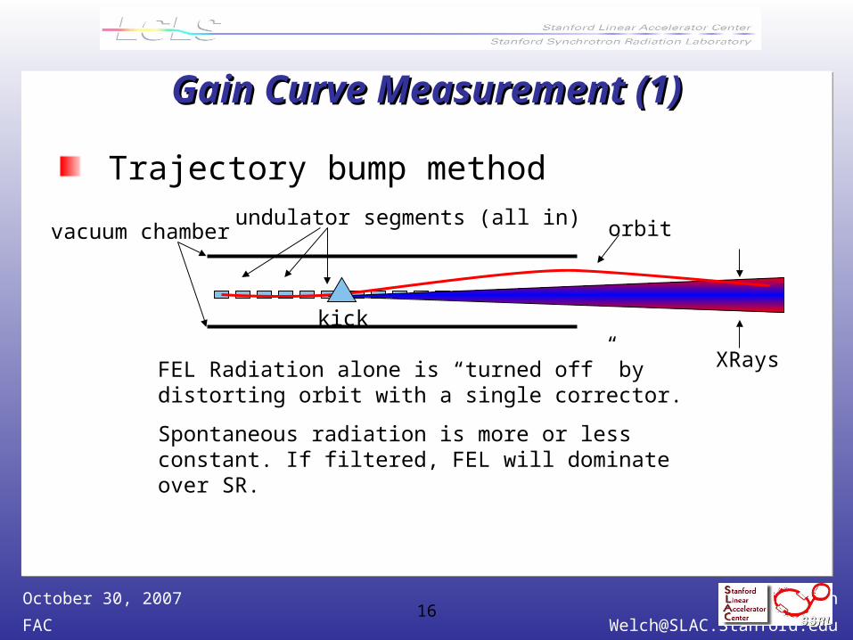
Gain Curve Measurement (1)Gain Curve Measurement (1)
Trajectory bump method
FEL Radiation alone is “turned off” by distorting orbit with a single corrector.
Spontaneous radiation is more or less constant. If filtered, FEL will dominate over SR.
orbitvacuum chamber
kick
undulator segments (all in)
XRays
James Welch
October 30, 200717
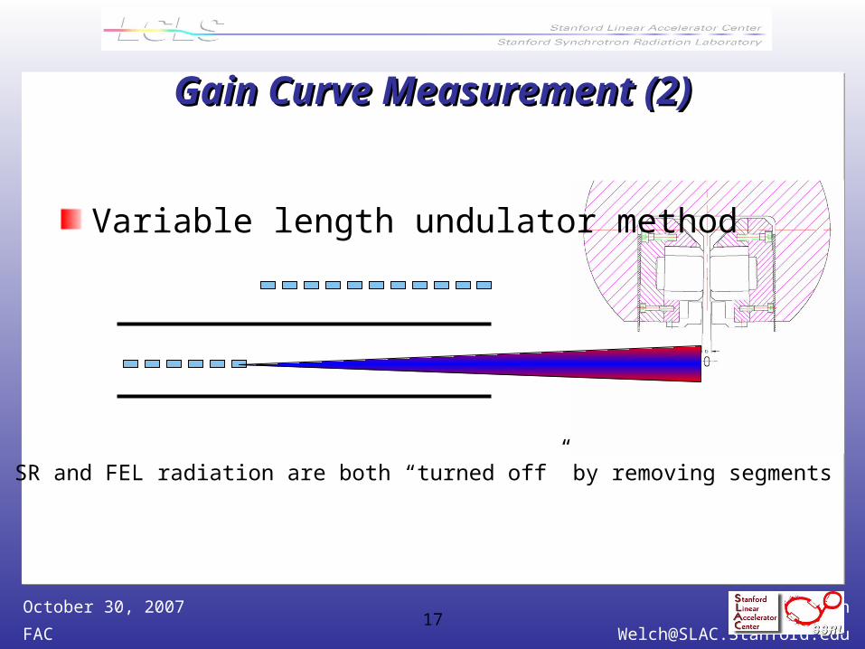
Gain Curve Measurement (2)Gain Curve Measurement (2)
Variable length undulator method
SR and FEL radiation are both “turned off” by removing segments

James Welch
October 30, 200718
Gain Optimization (just words)Gain Optimization (just words)
beta matching studies
bunch compression studies
laser heater studies
trajectory sensitivity studies
taper studies
. . .
James Welch
October 30, 200719
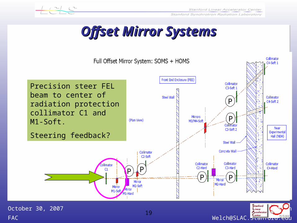
Offset Mirror SystemsOffset Mirror Systems
Precision steer the FEL beam onto the Mirror
system axis and keep it there.
FEL beam/mirror steering studies
FEL or Mirror axis Pointing system feedback
commissioning.
Get high energy FEL to work. Stabilize and
improve the beam quality.
P PP P
P
P
Precision steer FEL beam to center of radiation protection collimator C1 and M1-Soft.
Steering feedback?
James Welch
October 30, 200720
SummarySummary
Plans for intital FEL commissioning are shaping up.
Diagnostics tools are at, or passed, the concept phase
Methods for finding SASE and the central rays are identified.
Methods for gain curve measurements have been worked out
Overall planned duration is very short Considerable additional commissioning time will be needed especially for 0.15 nm radiation.