Embed Size (px)
Citation preview

Spring 2011 Beam Tests in Hall B
James McIntyreUniversity of Connecticut
GlueX Collaboration MeetingJLab, Feb. 2-4, 2011

Update on Delivered Prototype to JLab
• Preparations for Beam Test
• Lessons Learned
J. McIntyre, GlueX collaboration meeting, JLab, Feb. 2-4, 2011 2
Outline
Beam Test in Hall B
• Tagger Microscope
Testing: Detector Alignment Readout Time Resolution Efficiency Cross-talk

Beam Test in Hall B (cont.)
• Active Collimator
Overview of Design
Goal: Determine Bandwidth Limits of the Position Readout Test Updated Readout Test the Spatial Resolution Confirm Diagnosis of Anomalies from 2007 Beam
Test
3J. McIntyre, GlueX collaboration meeting, JLab, Feb. 2-4, 2011
Outline

Update on Delivered Prototype to JLab
► Delivered to JLab on Oct. 7, 2010 ◄
4J. McIntyre, GlueX collaboration meeting, JLab, Feb. 2-4, 2011
Front: Interior View
Bottom: Electronics
http://zeus.phys.uconn.edu/wiki/index.php/Delivery_of_the_Tagger_Microscope_Prototype_to_JLab

Preparations for Beam Test
Setup Control Computer (Software setup on JLab computer as per JLab requirements)
Setup Readout/Control for Tagger Microscope Installed controls for SiPM electronics Motor controls for alignment of SciFi focal plane
5
Update on Delivered Prototype to JLab
J. McIntyre, GlueX collaboration meeting, JLab, Feb. 2-4, 2011

Preparations for Beam Test
Bench Tests PerformedVerified: Ability to remotely control the step motors Appropriate implementation of motor limits Readout of the individual channels (pulse shape) Readout via fDAC and F1TDC
6
Update on Delivered Prototype to JLab
J. McIntyre, GlueX collaboration meeting, JLab, Feb. 2-4, 2011

7
Update on Delivered Prototype to JLab
J. McIntyre, GlueX collaboration meeting, JLab, Feb. 2-4, 2011
Lessons Learned
Fusing vs. Gluing of Fibers (MSU Splicing Unit)• Discussed during May 2010 Collaboration Meeting
• Stronger SciFi/waveguide joint• Better light transmission
• Air bubbles in glue & gluing gaps avoided• Specialized glass ferrules designed & ready to
order

8
Update on Delivered Prototype to JLab
J. McIntyre, GlueX collaboration meeting, JLab, Feb. 2-4, 2011
Lessons Learned
Board Layout Changes for Electronics• Backplane Board
Component clearances – Too conservative Components rearranged to provide better
clearance through prototype top-plate

Lessons Learned
Board Layout Changes for Electronics• Amplifier Board
Changes to the board’s layout are being implemented:
(Based on Fernando Barbosa’s recommendations)
Decrease inductance by ...• Optimization of layout/interconnections
We saw some resonances in the amplifier spectrum & distinct ringing in the tail of the signals indicating inductance
9
Update on Delivered Prototype to JLab
J. McIntyre, GlueX collaboration meeting, JLab, Feb. 2-4, 2011

Lessons Learned
Board Layout Changes for Electronics• Amplifier Board
Decrease cross-talk by... Optimize ground traces to improve Amp. circuit
isolation Improved layout of transistor DC level
distribution islands Spacing out the circuits, which is now possible
due the new more spacious radiation-conscious chamber design
10
Update on Delivered Prototype to JLab
J. McIntyre, GlueX collaboration meeting, JLab, Feb. 2-4, 2011

11
Update on Delivered Prototype to JLab
J. McIntyre, GlueX collaboration meeting, JLab, Feb. 2-4, 2011
Lessons Learned Neutron Radiation Damage to SiPMs
• SiPMs sensitive to neutron radiationGlueX-doc-1660-v2 ⇒ Calc. of radiation damage of SiPM in GlueX
SiPM Radiation Hardness Test ⇒ To predict life-time of SiPM detectors
• Neutron background estimatesGlueX-doc-1646-v1 ⇒ Neutron background estimates in tagger hall
Solution ⇒ Separate and Shield Electronics (i.e. SiPMs)Effective Damage to Si
DetectorRelative to 1MeV neutron
Electron vacuum pipe to beam
dump
Origin of neutrons which arrive in the Tagger
Microscope area

12
Update on Delivered Prototype to JLab
J. McIntyre, GlueX collaboration meeting, JLab, Feb. 2-4, 2011
Lessons Learned Neutron Shielding
Shielding Material
(Polyethylene)
Use concrete floor as
shielding

Tagger Microscope: Performance Features Under Test
• Detector Alignment Simulations show that when fiber axis is aligned to < 3o
of the e- trajectory ⇒ Adjacent signal amplitudes have a factor of 3 separation
Bench tests demonstrate alignment < 0.2o
• Readout First time SiPM signal will be read out with the
designated GlueX fADC and F1TDC modules Examine the output on the equipment actually
intended for reading out this detector
13
Beam Test in Hall B for Tagger Microscope
J. McIntyre, GlueX collaboration meeting, JLab, Feb. 2-4, 2011
Fiber Bundle D.o.F.
e- Trajectory

Tagger Microscope: Performance Features Under Test
• Time Resolution Requirement: 200ps time resolution BCF-20 SciFi → decay time 2.7ns Collective photon emission time uncertainty goes as:
2.7ns / √(Nγ)
⇒ Minimum of 183 detected photons is required to meet 200ps time resolution
specification
Simulations predict the mean photoelectron count > 300
14
Beam Test in Hall B for Tagger Microscope
J. McIntyre, GlueX collaboration meeting, JLab, Feb. 2-4, 2011

Tagger Microscope: Performance Features Under Test
• Efficiency Random arrival, in a single channel, of tagging e- result
in the occasional overlap of these finite pulses⇒ Resulting in the inability to resolve the two leading
edges While calculations are effective → measurement of the
pulse selection efficiency fed by pulses from an e- beam would be extremely useful
• Cross-talk Need to investigate the degree of cross-talk
between channels in a live beam Measure electronic cross-talk on the Amp.
Board Measure optical cross-talk between adjacent
fiber-SiPM junctions 15
Beam Test in Hall B for Tagger Microscope
J. McIntyre, GlueX collaboration meeting, JLab, Feb. 2-4, 2011

16
Beam Test in Hall B for Tagger Microscope
J. McIntyre, GlueX collaboration meeting, JLab, Feb. 2-4, 2011
x

17
Active Collimator
J. McIntyre, GlueX collaboration meeting, JLab, Feb. 2-4, 2011
γ Beam
Tungsten
Ejected e-
Insulator
Tungsten Wedges
Cathode
(+)
Anode
(-)
γ Beam
Φ 5mm.
Active Collimator ▶ Photon beam position monitor which will provide feedback to magnets upstream to ensure we thread through the collimators to the target.
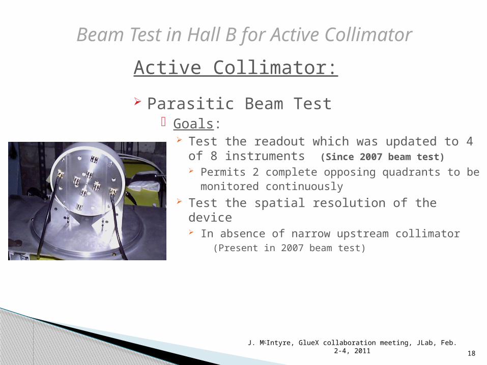
Active Collimator:
Parasitic Beam Test Goals:
Test the readout which was updated to 4 of 8 instruments (Since 2007 beam test) Permits 2 complete opposing quadrants to be
monitored continuously Test the spatial resolution of the device
In absence of narrow upstream collimator (Present in 2007 beam test)
18
Beam Test in Hall B for Active Collimator
J. McIntyre, GlueX collaboration meeting, JLab, Feb. 2-4, 2011
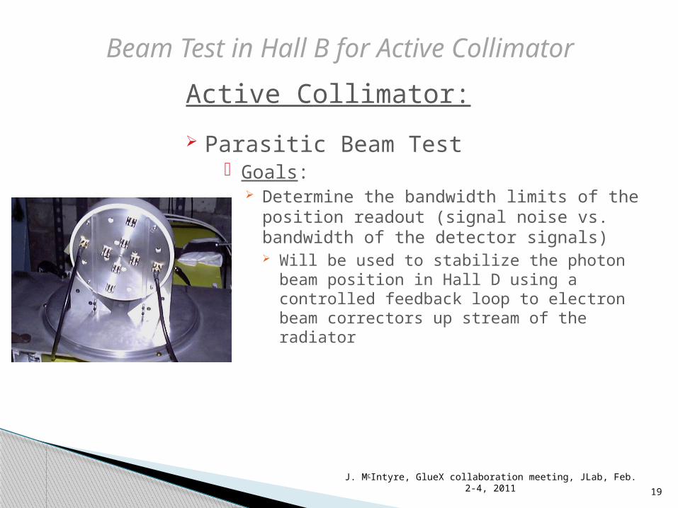
Active Collimator:
Parasitic Beam Test Goals:
Determine the bandwidth limits of the position readout (signal noise vs. bandwidth of the detector signals) Will be used to stabilize the photon beam
position in Hall D using a controlled feedback loop to electron beam correctors up stream of the radiator
19
Beam Test in Hall B for Active Collimator
J. McIntyre, GlueX collaboration meeting, JLab, Feb. 2-4, 2011

Active Collimator:
Parasitic Beam Test Goals:
Confirm anomalies in the 2007 beam test were correctly diagnosed and remedied successfully Larger than predicted currents (Good
thing)(By Geant3 simulation) Factor of 3.5 higher Geant3 result was sensitive to the lower cutoff on the
energy of the shower particles and deltas in the simulation
The P.E.E. that dominates photon absorption at energies < 100 keV is a complex Z-dependent function of energy that is described in an average way by Geant3
20
Beam Test in Hall B for Active Collimator
J. McIntyre, GlueX collaboration meeting, JLab, Feb. 2-4, 2011

Active Collimator:
Parasitic Beam Test Goals:
Confirm anomalies in the 2007 beam test were correctly diagnosed and remedied successfully Cross-talk
Relatively large response on inner wedge when the photon beam interacts in the outer wedge (peaks at 15.5cm & 22.0cm)
Simulation < 5% of peak current vs. ~ 25% during beam test
Possibility that the photon beam directed on the wedge not being readout caused charges to built up to a high voltage . Surface leakage currents drained the charge along the insulator to the nearest path to ground (which was through the adjacent wedge connected to the readout).
21
Beam Test in Hall B for Active Collimator
J. McIntyre, GlueX collaboration meeting, JLab, Feb. 2-4, 2011

Active Collimator:
Parasitic Beam Test Goals:
Confirm anomalies in the 2007 beam test were correctly diagnosed and remedied successfully Middle Peaks (Remedy: Use of 90o Connectors)
Peaks seen at 16.5cm & 21.0cm on both the inner and outer wedge readouts
Possibility that the readout cables hanging down in front of the detector acted as a pre-shower. The asymmetry between left and right most likely comes from the fact that one cable (16.5cm) hangs down from above, while the other (21.0cm) starts out from below, the center of the photon beam. Therefore one interacts with a smaller fraction of the beam than the other.
22
Beam Test in Hall B for Active Collimator
J. McIntyre, GlueX collaboration meeting, JLab, Feb. 2-4, 2011
Current measured on two outer wedges

23
Beam Test in Hall B for Active Collimator
J. McIntyre, GlueX collaboration meeting, JLab, Feb. 2-4, 2011
Beam line
Beam Dump

Questions?
J. McIntyre, GlueX collaboration meeting, JLab, Feb. 2-4, 2011