Embed Size (px)
Citation preview
AFML-TR-67-356
ELECTROPLATED NICKEL RAIN EROSIONRESISTANT COATING
JAMES H. WEAVER
TECHNICAL REPORT AFML-TR-67-358
JANUARY 1968
This document has been approved for publicrelease and sale; its distribution is unlimited.
AIR FORCE MATERIALS LABORATORYAIR FORCE SYSTEMS COMMAND
WRIGHT-PATTERSON AIR FORCE BASE, ONIO
1017 7 3S' ..
Best Available Copy -- "CLEAR I NG HO0US E
When Government drawig6, rip cificltionn, ur utther data are uqv'd for any p-rposeoh-- th,- n a- annectlon with a •finitely rel•"i * Govornment procurement oper.tion.
the United Statd Governmunt t hereby incurs no rusponsibility nor any obligation
whatsoever; and the fact that the Government may hnvre ormulo~sd, furnithod, or in
any way supplied the said drawingr, Fpooifications, or other data, is not to b• rg~trdb4
by implication or otherwise as iLn any manner licensing the holder or any other person
or corporation, or conveying any rights or permission to manufacture, use, or sell any
patented inventivu UWut may in any %;ay be rlutcd t~her-tv.
This document has been spproved for public release and sale; its distribution Isunlimited.
Copies of this report should not be returned unless return is required by securityconsiderations, contractual obligAtions, or notice on a specific document.
400 - Fabnxua 1968- C04M - 2S-SS7

A I I I -'A I -3i
ELECTROPLATED NICKEL RAIN EROSIONRESISTANT COATING
JAMES H. WEAVEIR
ThiB do urnent has been approved for publicrelease and sale; its distribution is unlimited.
1., ,

A FM L-TR-67-356
FOREWORD
This report was prepared by the Elastomers and Coatings Branch, Nonmetallic Materials""'Division, Air Force Materials Laboratory, Air Force Systems Command, Wright-PattersonAir Force Base, Ohio. The work was initiated under Project No. 7340, "Nonmetallic and Com-posite Materials," Task No. 734007, "Coatings for Energy Utilization, Control and ProtectiveFunctions," and was administered under the direction of the Air Force Materials Laboratory,Mr. James H. Weaver (MANE), Project Erhglneer.
This report covers work conducted from July 1965 to September 1966. The report wassubmitted by the author in August 1967.
The autho: gratefully acknowledges the assistance ofr, r. Roger Vissoc, University of DaytonResearch Institute, during the experimental portion of the program.
This technical report has been reviewed and is approved.
W. g. OHNSONActing Chief, Elastomers and Coatings BranchNonmetallic Materials DivisiorAir Force Materials Laboratory
AFM L-TR-67-356
ABSTRACT
The problem of protection of plastic components of advanced aircraft and missile weaponsystems from the damaging effect of rain impingement at high speeds is severe and willbecome more severe in the future. Metal coating of plastic laminates is particularly ap-plicable to plastic structural members such as wing leading edge of aircraft, helicopterrotor blades, and turbine engine compressor blades.
Epoxy, polyester, and polybenzimidazole laminates were electroplated with a minimum of12 mil of nickel and exposed to a rain environment at subsonic speeds. The plated epoxyendured 160 minutes, the plated polyester 180 minutes, and the plated polybenzimidazole473 minutes with no visible evidence of erosion. The latter represents a 40-fold increase inresistance over specification neoprene coatings. Supersonic rocket sld test runs at Mach 1.5and 2. G showed no evidence of erosion. The 60-degree angle exposure at Mach 2.5 showed milddamage. Electroformed nickel patches were bonded to stabilizer edges of an F-100 airplanewhich subsequently made a total of 163 penetrations into rain and hail storms for a total timeof 440 minutes with no indication of erosion of the electroformed nickel.
Substrate preparation and nickel thickness were found to be the most important criteria forobtaining good rain erosion resistant coatings. Mechanical interlocking achieved by sand-blasting appears to be the most efficient method to obtain adhesion to the inert surface. Aminimum thickness of 12 mil of the nickol coating on the laminates is recommended to obtainprotection from rain erosion.
A\ F I"1,-FI1 -67(-356
T'ABIP. O)F ('()NT'N'i
FC TI(N )PAGE
I I'NTHw1C)1)'('TION I
Ii NICKIEI. C(.ATING PiHOIF"TITIES 1
ItI E.VALUATION TFC1lNIqhU-S 2
IV EXPIERIMENTAL 2
1. Substrate Material 2
2. Substratt- Preparation 2
3. Specimen Configuration 3
L E 3ULTS 4
1, Adhesion 4
2. Effects of Thermal Cycling 4
3. Effects of Nickel-Coating Thickness 4
4. Effects of Surface Roughness 5
5. Supersonic Sled Tests 6
6. Project Rough Rider Tests 6
'.'I CONCLUSIONS 6
RFFERFNCFS 7
V

\ FMIL-TlT-67 -356
1I,LUSTIH\TI( )NS
FIG UL It F PAU F
Pa1. in _reomson Fanility - .p ray tlng and Whirling Arm 8
2. Rain Eroilorn Facility - Spray Pting, Whirling Arm WithS"Test Siecimen lnsqLalhLLI. and Ptriscope Tube 9
3. Wedge Mounted on the Front o: Rocket Engine 10
4. Specimen Configurations 1.1
5. Photomicrograph of Three Plating Thicknesses 12
9, Adhesion Tests 13
7. Enplate Conditioner Adhesion Tests 14
8, Assembly Adhesion Tests 15
9. "As-Received" and Sandblasted PB! Specimens
10, Uncoated PBI Laminate After a Six-Minute Exposure 17
11. Six-Mil Nickel-Plated PBI After a 46-Minute Exposure 18
12. Sixteen-MIl Nickel-Plated PBI After an 840-Minute Exposure 19
13. Thickness vs Time for Rain Erosion Coated Specimens 20
14, Effects of Smooth and Rough Surfaces on Time-to-FaIlure 21
15. Sled Test Results 22
16. Electroformed Nickel Bonded to Vertical Stabilizer 23
vi

A Ft:M IL-Tl{ -67-306
SECTION I
INTRODUCTION
Thei phe,•,i.nnon ,)f rain ero.imn ha.'i been described by ,ahl (lieierenct. 1). During thererearch offort covered by this rupcurt, however, the effect of uirface roughness on theerosion resistance of nickel electroplated laminates was nuted. Thi, saugrgstd mechanismis that a3 r•oigh ,O•,'f',- hri-k. thk r, ir,.,I, into gmml fragments .nd c •nsequently has lesssevere impingement impact. The smaller particles also produce less rtdial flow and theshear stresser are smaller, This theory h4.5 been studied and is Fhscribdcl in thig ruwixrt.
SECTT(XI fII
NICKEL COATING PROPERTIES
Nickel Is the most widely used nietal forengineerlng applications because of the mechanicalproperties obtainable and a more profound knowledge of nickel-plating solutions pertinent tothis type of application, By proper selection of a nickel bath and its operating conditions, onecan control hardness, density, tensile strength, stress, and rate of deposition to meet almostany design requirement. Excessively high stresses resulting frorn certain nickel baths cancau"e peeling, cracking, crazing. warping, blistering, distortion, shrinkage. and even com-plete destruction and failure of structural units or protective coatings. Howeve. a nickelsulfamate bath is capable of producing the type of mechanical prorprties desired for rainerosion protection, The properties considered most important are high hardness, increasedductility, and low tensile stress. Typical mechanical properties produced by sulfarate nickelbaths are:
Hardness 150 to 350 VHN
Tensile Strength 60,000 to 100.000 psi
Elongation in 2 In. 10 to 301
Internal Stress 500 to 7000 psi, tensile
Several investigators have corrda Lhe internal stress levels with processlitg conditions(Reference 2). Where higher current uensities are required to achieve desired mechanicalproperties, stress reducers can be used to maintain the desired stress values. These stressreducers will also Increase hardness which is desirable for rain erosion protection.
I:
A FM 1-4-';7-3"4
SECTION M
EVALUATION TECIINIQUES
A whirling arm facility located at % right- ,atttvr.on Air Force li4me was ii.•,ed for thesubsonic evaluations. This facility Incllkded a 6 ft diamnater .steel hlade muuntu'd on a 1O0-hpizAt. T-hnt rz-ii Ayvitum waK cunrA-s&ri of i hypodermic needicf:. seit-'tied for proper d- 'yp size%1.5 to 2.0 m.11 diamnt.r) on a 6-ft dlianiter pipe ring. A strohx)scopic uilt aml 1wriscope
arrangement enabled observation of the specinten while running (see Figures 1 And 2). Thevcloctty was 500 mph and 2.0 Inches per hoCur of rainfall.
For supersonic evaluations a r,.ý-t sltt.l fGcility was uased, Multiple flat samples- wereplaced on a wedge in posltions such that impact with the rain-drops wrold be at variouls angles.The wedge was mounted on a sled which was propelled by rocket motors through a calibratedrainfall at the desired velocities. The sled test facility is located at Holloman Air Force Base.New Mexico. and operates on a monorail 35,000 ft long, The facility has a 6000 ft longartificial rainfall. The test velocities -,nged from Mach 1,3 t• 2.5 and the rainfleld produced2.5 inches per hour. The water droplet sizes range from 1 to 2 inm in diameter. Figure 3shows the wedge mounted on the front of the rocket engine.
SECTION IV
EXPERIMENTAL
I. SUBSTRATE INI .'ERIAL
Polybenzlmidazole (PBI) was chosen as representative of high temperature, high strengthplastic materials being considered for future applications such as helicopter blades, leadingedges, and vertical stabilizers. Reinforced epoxies and polyesters were chosen as typicalrepresentatives of materials used for present day ;..plications.
2. SUBSTRATE PREPARATION
The preparatory treatments of the inert plastic surface govern the success or failure of anyprocess for application ofthe inltialchemlcally reduced filrn, The same processing procedureswere used for all plastic substrate materials.
2

.'A I ML-Y I U AL4,
I-he fnryniti. n of ai . ,U ; ,' . tlndud tI i 4414 '1 .•| )'l' id oe!. •l Willf I ' ? , ,I roh'lr-- Thc• ft 1, ,Al• I tiuj,1:
1. Ioighf.'ni ng or dvg'.cir'ng
2. C I'tlv;tning it- 5rt w.r
'I Svn.- itil;fI ng the i
S. Ac~tiva;ting thc Surfiwte
6. Iurn I iig thtv ,I~ttj, ivKI filmo by cht-rn letl I :t-1itinn
"Th" atx)ve proccEIng q•p•.ps 4r, uI,.,scrile,,i in ,tlill in liefermnce 3.
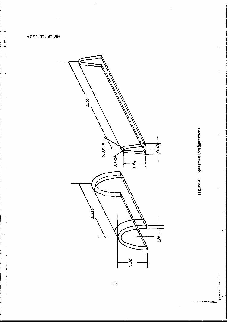
-3. ?I•PlE IMEN CO(N FIGUIATION
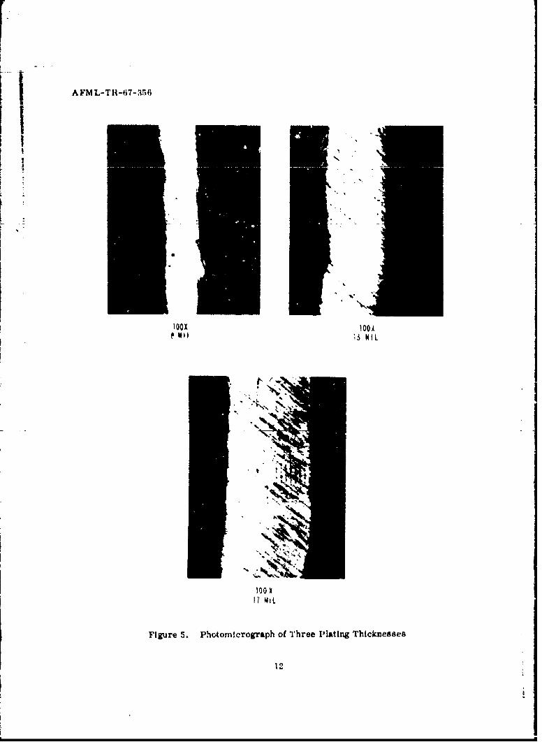
iDuring this research effort, the sample configuration for the whirling arm evaluation rigvaried. Figure 4 shows the two configurations used. The current dcnmity distributior, variedfrorm the edge of the specimen to the center of the curvature. Sinct thc raindrop impingenientis on the curved portion of the specimen, thickness determinations were rIl|de at this point.Thickness was determined by sectioning a sample at the leading edge. and mounting, polishingand measuring the plating thickness on photomicrographs. Figure 5 shows the thickness ofthree samples. Fach unit is equal to 1 mil. Tne samples for the sled tests were flat and1,25 x 1,25 x 0.25 Inchus in size.
3
A FM L-TR-67-356
SECTION V
RESULTS
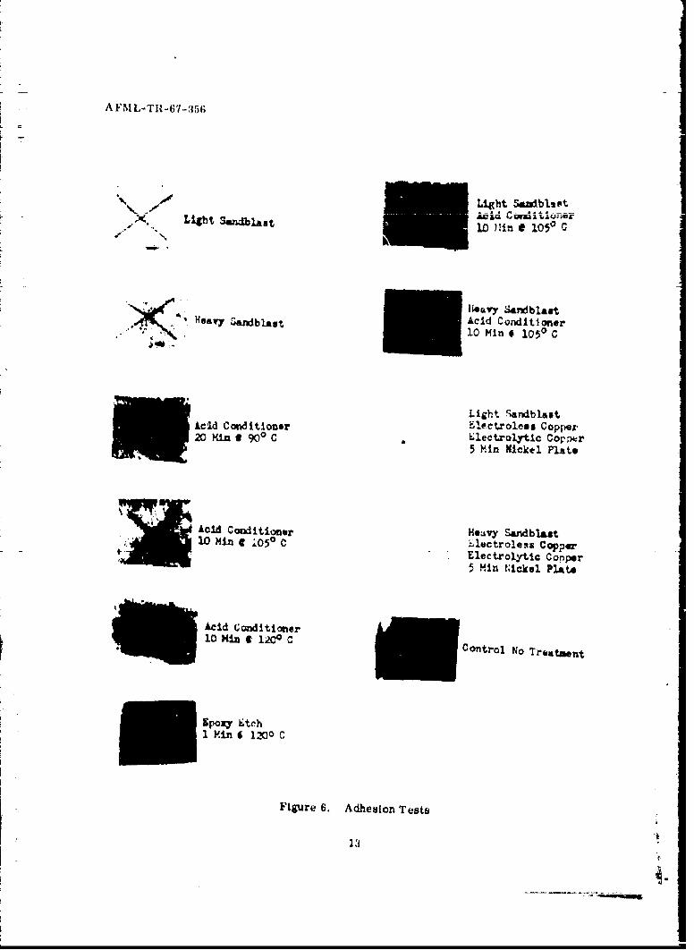
" ADHESION
Substrates of epoxy were roughened by the various conditions otlined In Iteference 3. Theywere serfitized, aciivated, ani plated for 10 minutes in the electroless copper bath. Someof the light and hea',y sandblasted samples were given a copper flash and were nickel-platedfor five minutes to check the adhesion of the vombined plating system. The samples wererrissm"rked with a sharp instrumcnt using an much pressure as poss;btc. One inch Scutch
tape was applied immediately to the crossmark. The tape was pressed tightly against thesurface of tne coating using the thumbnail to work the tape into the rough surface. The tapewas removeu with one quick 180-degree motion. IThe results of the tape test are shown inFigure 6. It can be seen that thL sandbhsted samples gave superior adhesion as compareo tothose prepared using the acid conditioner, The adhesion of the combined plating system wasvery good. Tte proprietary conditioner was used to condition the samplt s and the results areshown in Figure 7. The light sandblasting and the proprietary conditioner gave excellent ad-hesion.
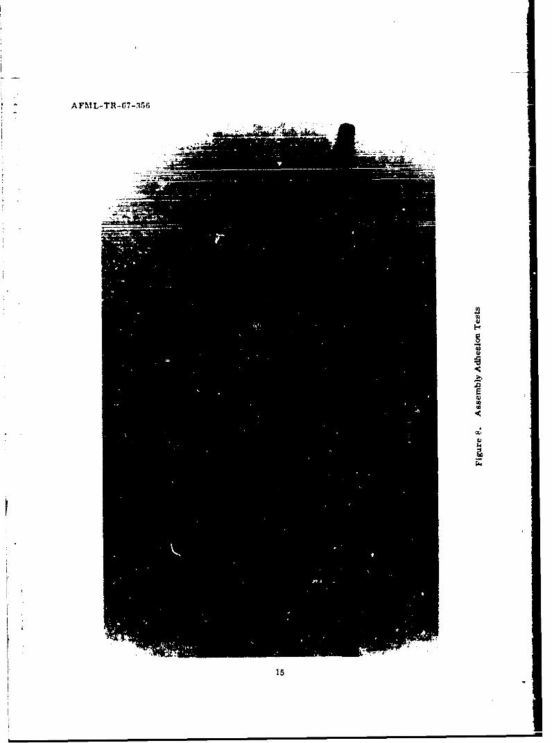
The adhesion of the electroless copper to the substrate had been determined by qualitativetests (tape test), but it was deemed important to have a quantitative measure of the strengthof the bond between the electroless copper and the substrate. The test used consisted ofbonding the electroless copper to an epoxy substrate with an adhesive, and then measuring theforce needed to pull the assembly apart, Figure 8 shows the assemblies after failure. Num-brs 2 and 3 failed it. the adhesive and epoxy laminate, respectively, while number 1 was acohesie failure in the copper. Fallureoccurred at 450 pli, In all cases the failure occurred inthe assembly prior to failure of the bond between the electroless copper and the substrate.Mechanical Interlocking such as achieved by the sandblasting appears to be the most efft.clentmethod to obtain adhesion of the elect-oless copper to the inert surface.
2, EFFECTS OF THERMAL CYCLING
Since the leading edge ofa high speed component would be subjected to thermal cycling duringopei tion, a thermal cycling ewduation was initiated, Two samples of each substrate materialwhich had been electroplated with uickel (12 to 16 mil) were thermal cycled. The maximumtemperature expos, re for the epoxy was 149'C (300'F), the polyester 122'C '0P), and thePBI 313-C (600'F). These samples were heated at these temperatures for 30 minutes, aircooled, and the cycle repeated 10 times. There was indication of blistering on one polyestersample. All other samples, however, were free of visual defects. These samples wereexposed to the simulated rainfall at 500 mph an additional 50 minutes to determine if anydamage had been caused by the thermal c/cling It was determined that the thermal cyclingprod,iced no adverse 'ffects on the rain erosion resistan-•e of the nickel-plating.
3. E,'FECTS OF NICKEL-COATING THICKNESS
The thickness of the nickel deposit is very critical for successful rain erosion resistance.in the Initial stages of t,.e research, thicknesses in the range of 4 to 8 mil were evaluated.The times-to-failure were greatly improved over the neoprene coatings (rain erosion speci-fication material) when exposed tcothe 500 mph in 2-inch per hour simulated rainfall. Neoprenecoatings 10 to 12 miol thick failed in 5 to 8 minutes when exposed to t-.e rait, enwironmenit at500 mph. Inc reased thickness of the nickel seemed feasible so thicknesses were then increasedup to 16 mi. Table I shows the rusults obtained.
4
A FML ,-THI-67-356
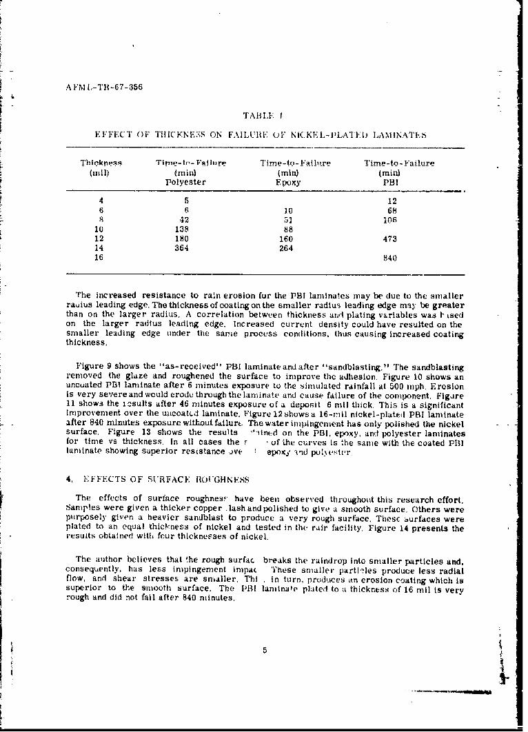
TABLE I
EFFECT OF TIlICKNESS ON FAILUIRIE OF NiCKEL-I•LA'I'AD LAMINATES
"Thlnkneo . Time-tn- F•_!urp Time-tc- Failure Time-to- Failure(ri) (min) (min) (min)
Polyester Epoxy PHI
4 5 126 6 10 688 42 52 106
10 138 8812 180 160 47314 364 26416 840
The increased resistance to raln erosion for the PBI laminates may be due to the smallerrauius leading edge. The thickness of coating on the smaller radius leading edge may be greaterthan on the larger radius, A correlation betw-,en thickness and plating variables was I' tsedon the larger radius leading edge. Increased current density could have resulted on thesmaller leading edge under the same process conditions, thus causing increased coatingthickness.
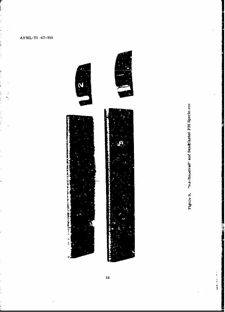
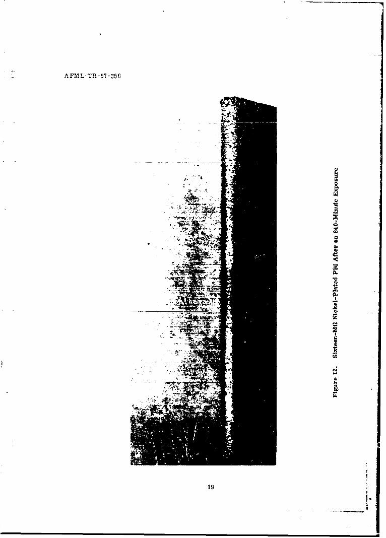
Figure 9 shows the "as-received" PBI laminate and after "sandblasting." The sandblastingremoved the glaze and roughened the surface to improve the adhesion. Figure 10 shows anuncuated PB! laminate after 6 minutes exposure to the simulated rainfall at 500 mph. Erosionis very severe and would erode through the laminate and cause failure of the component. Figure11 shows the iýsults after 46 minutes exposure of a deposit 6 mtl thick. This is a significantimprovement over the uicoatcd laminate. Figure 12 shows a 16-mil nickel-platedi PBI laminateafter 840 minutes exposure without fAilurt- The water Impingement has only polished the nickelsurface. Figure 13 shows the results '4'int-d on the PBI, epoxy, and polyester laminatesfor time vs thickness. In all cases the F , of the curves is "he same with the coated Fl!laminate showing superior resistance v(ve 1 epoxy and puv, ster.
4. EFFECTS OF SURFACE ROUGHNESS
The effects of surface roughnes: have been observed throughout this research effort.Samples were given a thicker copper lash and polished to give a smooth surface. Others werepurposely given a heavier sandblast to produce a very rough surface. Thesc :urfaces wereplated to an equal thickness of nickel and tested in the rair facility, Figure 14 presents theresults obtained with fcur thicknesses of nickel.
The author believes that the rough surfac breaks the raindrop into smaller particles and.consequently, has less impingement inipac These smaller particles produce less radialflow, and shear stresses are smaller. Thi , in turn, produces d.n erosion coating which issuperior to the smooth surface. The P1I laminate plated to a thickness of 16 mil is veryrough and did not fail after 840 minutes,
5
.............................
I1

5. SUPEHSONIC SLED TESTS
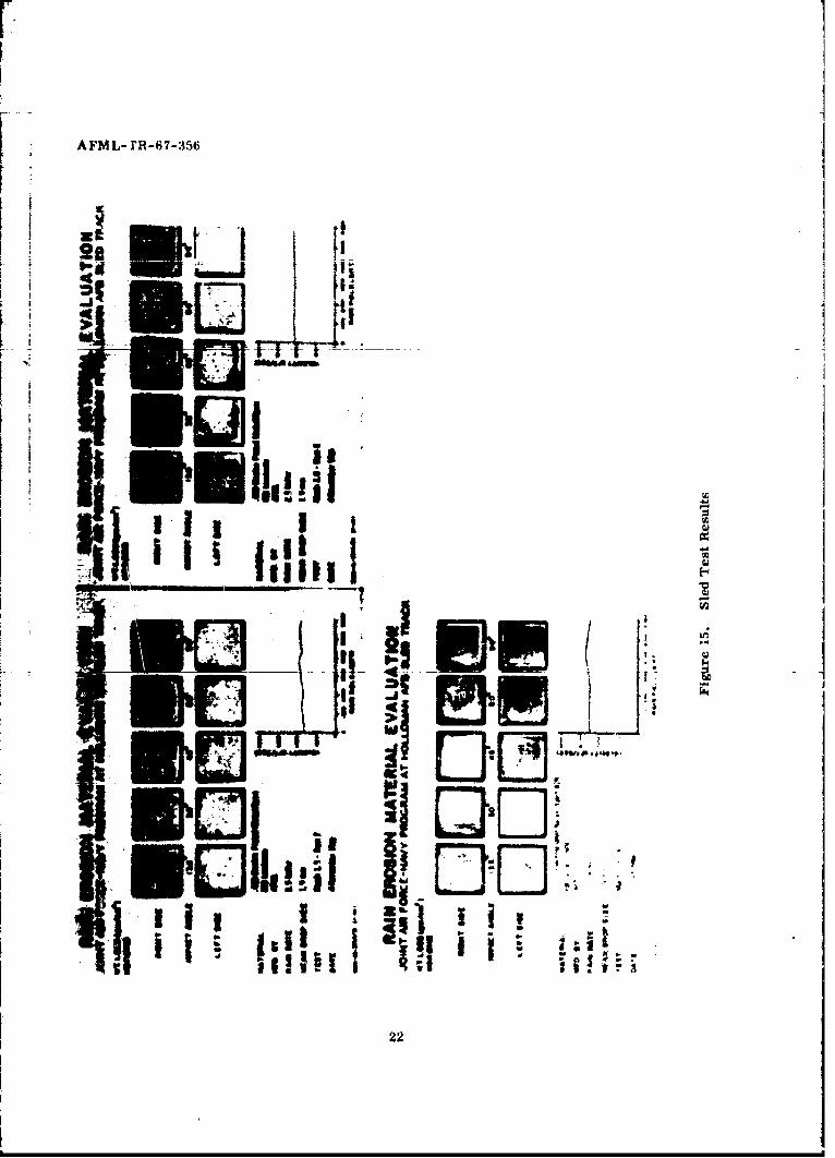
Sobsonio evaluations of nickel electroplated laminates have indicated 40 times the resistt-ance over the elastomeric and ceramic coatings. The ductility of the nickel (elongation upto 2 0%.) is feit to be chiefly rspuonsibie for this resistance. Epoxy laminaies (1,25 x 1.5x 0.=5 inches) were electoplated to a thickness of 10 rail and placed in the wedge at variousangles (15'. 30', 45'. 60', and 90). Figure 15 shows the results of the sled test at Mach 1.5.2.0, and 2.5. At Mach 1.5 and 2.0 the nickel electroplating appeared unexposed after thefirings. At Mach 2.5, specimens at all positions except 60 degrees also appeared unaffected.At 60 degrees the surface of the nickel had been deformed and ridges appeared where ithad been pushed up Or "wrinkled" by the radially flowing water. The 60-dgree nickel elec-troplated samples had lost adhesion but were not penetrated by the water drops. Futu-e testswill include different thicknesses of nickel electroplated on other laminates and tested up toMach 5.0.
6, PROJECT ROUGH RIDER TESTS
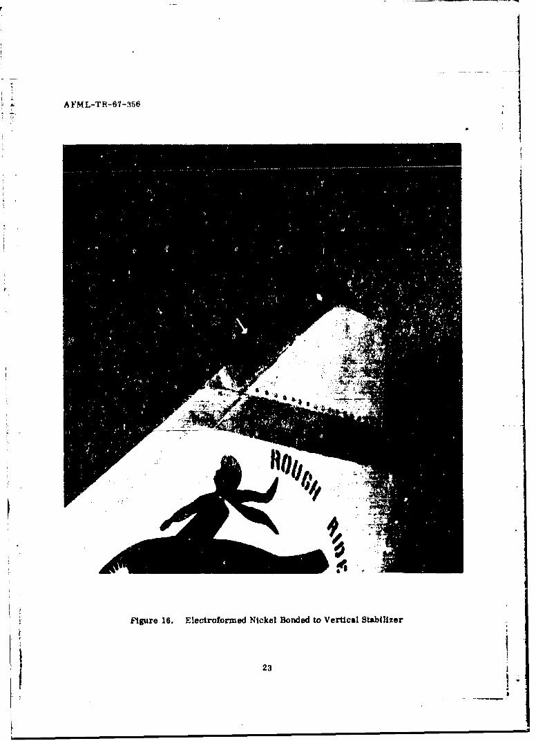
A practical evaluation of rain erosion resistant coatings was initiated known as ProjectRough Rider. For this program, "patches" of experimental coatings were applied to variousareas of an F-100 airplane which penetrated rain storms to check the erosion of materialsdue to repeated impact of raindrops. Electroformed nickel patches were bonded to the leadingedges of each horizontal stabilizer and on the vertical stabilizer. Figure 16 shows the nickelarna on the vertical stabilizer. One hundred sixty-three penetrations were made at 275 knotsindicated air speed from 25,000 to 35,000 feet. The total accumulated time in the storms was440 minutes. All electroformed nickel patches remained in excellent condition with noindication of erosion.
SECTION VI
CONCLUSIONS
Procedures have been established for nickel-plating nonconductive substrates for rainerosion resistance. By careful control, a fine grained. low stress nickel deposit which hasexcellent adhesion, hardness, and ductility is produced. The advanced process has beensuccessfully applied to epoxy, polyester, and PBI laminates and ext-nded the life of normalleading edge materials some 40 times when compared to the spoctihcation neoprene materialfor subsonic applications The supersonic rocket sled test runs at Mach 1.5, 2.0, and 2.5were very successful with only the 60-degree angle shov ing any evidence of damage fromthe rAindrop impingement. The electroformed nickel patches on the F-100 airplane endureda total of 163 penetrations for a total time of 440 minutes with no indication of erosion. Su-perio," erosion resistance is obtained by roughening the surface slightly. The same procedureswere used for each substrate with equal succesa, It was determined that the thickness ofnickel be a minimum of 12 mil on the laminates to obtain extended life of a leading edge.
6

A FM L-TH-67-356
REk:FERENCE S
1. N. F, Wahl, Investigation of th Phenomena of 2Rain Frosion at Subsonic and Supersonici RSj• , AFMIL-T11-65-330, Air lurce Mlaterials Laboratory, Wright- Patterson Air
Force Base, Ohio, October 1965.
2. D. A. I:anner and . A. F. Hammond. Transactions, Inst. Metal Finishli, Vol 36, Part 2.1958 1959, p 3 2.
3. J. H. We.aver. "Nickel Electroplated Nonconductive Materials for Protection from RainFrosiorn, Plating, May 1967,
7

AFML-TY-0'-356
Figure 1. Rain Erosion Facility -Spray Ring and Whirling Arm

AFML-TH-637.3fl6
I.0
Figure 2. Rain Erosion Facility -Spray Ring, Whirling Arm With Test SpecimenInstalled, and Periscope Tube
9

11
I0
I-1
8*4
\\ \
2
0, 0 U0
4
C1
11
K
A FM L-Tit-67-356
, L
Fiur S. Phtmcorp
ofTrePa
inThcess
[1
I III
10 l
1 00Ap iI t
3 , NIL
'I
i
Figure 5. Photomicrograph of Three Plating Thicknesses
A F•ML-TII-67-3:56
"N 7 Light Satb1rt
A ,N Light Sandblast -,05lm 09 C
Heavy SandblastHeavy Sandblast Acid Conditioner10 Min f 1050 C
Light Sandblast
Acid Conditioner blectrolema Copper-20 MinE 900 C Electrolytic Coper
5 Min Nickel Plate
"Acid Conditioner Me..vy Sandblast10 MiLn 9 105o C -lectroless Copper
Electrolytic Co nper5 Min Nickel Plate
Acid •onditioner10 kin £ 120. C Control No Treatment
Epoxy EtchI piLn 4 I•-mo C
Figure 6. Adhesion Tests
13 '

AFML-Tit-67-,156
~.L.FSandblast
Sandblasti •5 MIA Up:late Acid
Ct,nditioner a 600 C
U Sandblast5 Kin lnpate AcidConditiomw 75o C
Sandb last5Min EnPlate Acid
Conditioner Ti P50 C
onplat. Acid
Conditloner5 Min e 85o C
Figure 7. Enplate Conditioner Adheaiton Tests
14
AFML-Tfl-67-156
15
AFML-TI -67-356
th
pq
I:I
16

A FINL-TH-C'7-356
Via
CzJ
17i

rr[ AFM-TR-7-35
18.
AFLT1-6i7-356
. Itq
7Wz

A FML-TH-67-356
* i!
IV
ca
ccS 4)
203
['.i4

:- ~AFM L-TR-6i7-35(6
110
140 KEY
120 S•.•OTH
. 100 ROTLIA
so
1.so
40
205 I/ -
THICKINESS, NILS
FIgure 14. Effects of Smooth &nd Rough Surfaces on Time-to-Failure
21
IIL:a
AFML-rR-67-35f
hi
lU *
*El. m
l~it
SI 0
I.:_ I I I I tll!Ei I I 1 , 22
22
AFML-TR-61-356
Figure 16. Electroformed Nickel Bonded to Vertical Stabilizer
23 1

*DOCUMtNT CONTROL DATA R&DV
Wright- 1attv-rimn AIr Force 1415w. (Ohio I133
~ C RoPA1 E) ~1L RAIN EH(NlUN lIFiSlSTANT C()ATiNOi
-4 11C'~r It Nar'l ["P# '.. ttAff W4 If~tituow JAi*13
July I1965 to september. 1966
Weaver, James 11.
4 fNJ M * 0 *1 OA It'*~N ' 'OtEr
IX-vember 10)67 32 __________
II.. CON I R.C = 09 GRA 'NT .0 00.NQ A 10.4- *4 'O- N .*4 "gal
Task Noi. 734007 *P1 1, * -0-1 41 rAt,, a.IPh. .1 .# bA*I b.~ 0. 1 AV, -1
This document has been approved for public release and sale; its distribution is unlimited.
It I UPPL &"IN A v - OTV I0501 I" -& .R. .,; a
Air Forcu Alatrials LaboratoryWright-l~atterson Air Force Base, ohio
454:33
The problem of protection of plastic components of advanct-d aireraft and missile weaponsystenit from the damaging effect of rain Impingement at high speeds is severe and will becomemore severe in the future. Metal coating of plastic laminates is particularly applicable toplastic structural members such as wing leading edge of aircraft, helicopter rotor blades,and turbine engine compressor blades.
Epoxy, polyester, and polybenzlrnidazole laminates were electroplated %kith a minimum of12 mil of nickel and exposed to a rain environment at subsonic speeds. The plated epoxyendured 160 minutes, the plated polyester 180 minutes, and tho plated polybenzimidazole473 minutes with no visible evidence of erosion. The latter represents a '10-fold increasein resistance over specification neoprene coatings. Supersonic rrocket sled test runs atMach 1. 5 and 2. 0 showed no evidence of erosion. The (6)-degree angle exposure at Mach 2. 5showed mild damnage. Electrofornmed nickel patches were bonded to stal.i~cr edges of anF-100 airplane which subsequently made a total (if 16.1 penetrations Into rain and hail stormisfor a total timec of 4140 minutes with no Indic2ation (if erosion tf the eleetrotornwd nickel.
Substrate prep~aration and nickel thickness were found tP be the most important criteria forobtaining goo~d rain erosion resistant coatings. Mechanical interlocking achieved by sand-blasting appears to he the most vfficient mt-thod to obtain adhesion to the inert surface. Aminimum thickness of ILI n~il of the nickel coating on thc lanmiimtes Is re-commended toobtain p~rotection from rain erosion.
D D J¶. 14 73 U~nclassified _______
0 .- A 0
"Ickel Flv-r -ot -
Nickel Electrofornfu~i
_____Unc 1Rif~tedwisa II Clu~tIIm t, imo