Embed Size (px)
Citation preview

8/20/2019 J5155124 Berne, NY Tower Geotechnical Report (Sealed) 11-6-15
http://slidepdf.com/reader/full/j5155124-berne-ny-tower-geotechnical-report-sealed-11-6-15 1/25
Geotechnical Engineering ReportProposed Telecommunications Tower
Berne, New York
November 6, 2015
Terracon Project No. J5155124
Prepared for:
Pyramid Network Services, LLC
East Syracuse, New York
Prepared by:Terracon Consultants – NY, Inc.
Rochester, New York

8/20/2019 J5155124 Berne, NY Tower Geotechnical Report (Sealed) 11-6-15
http://slidepdf.com/reader/full/j5155124-berne-ny-tower-geotechnical-report-sealed-11-6-15 2/25

8/20/2019 J5155124 Berne, NY Tower Geotechnical Report (Sealed) 11-6-15
http://slidepdf.com/reader/full/j5155124-berne-ny-tower-geotechnical-report-sealed-11-6-15 3/25

8/20/2019 J5155124 Berne, NY Tower Geotechnical Report (Sealed) 11-6-15
http://slidepdf.com/reader/full/j5155124-berne-ny-tower-geotechnical-report-sealed-11-6-15 4/25

8/20/2019 J5155124 Berne, NY Tower Geotechnical Report (Sealed) 11-6-15
http://slidepdf.com/reader/full/j5155124-berne-ny-tower-geotechnical-report-sealed-11-6-15 5/25

8/20/2019 J5155124 Berne, NY Tower Geotechnical Report (Sealed) 11-6-15
http://slidepdf.com/reader/full/j5155124-berne-ny-tower-geotechnical-report-sealed-11-6-15 6/25
Geotechnical Engineering Report
Proposed Telecommunications Tower ■ Berne, New York
November 6, 2015 ■ Terracon Project No. J5155124
Responsive ■ Resourceful ■ Reliable 2
Item Description
Site Layout Exploration Location Diagram on Exhibit A-2, Appendix A
Structures
New 180-foot high steel self-supporting lattice telecommunications
tower and associated equipment shelters and ground equipment
within an approximately 50-foot by 60-foot fenced compound area.
Estimated Maximum LoadsTower dead load: 50 kips
Equipment shelter: 150 pounds per square foot (psf)
GradingMinor grading (cuts and fills up to about 1 to 2 feet) will be required
to develop the compound area.
2.2 Site Location and Descr iption
Item Description
Location 28 Jansen Lane, Berne, New York.
Existing Improvements The site is undeveloped in the area of the proposed tower.
Current Ground Cover Forest mat.
Existing Topography 1
The site slopes slightly downward to the northeast in the vicinity of
the proposed tower from approximate Elevation (El) = 1449 to 1447
feet.
1. Elevations taken from a plan by Infinigy Solutions, LLC of Albany, New York, titled “Overall Site
Plan”, sheet No. C3A, revised February 23, 2015.
3.0 SUBSURFACE EXPLORATIONS AND CONDITIONS
3.1 Typical Profile
Based on the results of the explorations and observations at the time of drilling, subsurface
conditions on the project site can be generalized as follows:
Description
Approximate Depth to
Bottom of Stratum
(feet)
Material Encountered 1
Consistency /
Relative
Density
Bedrock >20.2Shale, moderately weathered,
weak, very thin beddingNA
1. Approximately 6 inches of forest mat and 12 inches of subsoil were encountered at the surface of
the boring.
The Surficial Geologic Map of New York – Hudson-Mohawk Sheet (1987) identifies native soils
in the vicinity of the site as exposed glacial till or bedrock outcrops. Bedrock was encountered

8/20/2019 J5155124 Berne, NY Tower Geotechnical Report (Sealed) 11-6-15
http://slidepdf.com/reader/full/j5155124-berne-ny-tower-geotechnical-report-sealed-11-6-15 7/25
Geotechnical Engineering Report
Proposed Telecommunications Tower ■ Berne, New York
November 6, 2015 ■ Terracon Project No. J5155124
Responsive ■ Resourceful ■ Reliable 3
near the ground surface just below surficial organic soils. The Geologic Map of New York –
Hudson-Mohawk Sheet (1970) indicates that bedrock in the vicinity of the site consists of shale,
sandstone, or limestone. B-1 was terminated at a depth of approximately 20 feet below existing
grade after auger drilling through about 18.5 feet of shale bedrock.
Conditions encountered at the exploration location are indicated on the exploration log in Appendix
A of this report. Stratification boundaries on the exploration log represent the approximate location
of changes in soil/rock types; in situ, the transition between materials may be gradual. Further
details of the exploration can be found on the exploration log.
3.2 Groundwater
Groundwater was not encountered in the exploration. However, fluctuations in groundwater level
may occur because of seasonal variations in the amount of rainfall, runoff, and other factors. In
addition, water may become temporarily perched over the bedrock. The possibility of
groundwater level fluctuations should be considered when developing the design and
construction plans for the project.
3.3 In-situ Resistivity
On October 21, 2015, a Terracon field engineer completed in-situ soil resistivity testing in
general accordance with ASTM G57 by the Wenner Four Probe Method. The testing was
completed using a Megger DET5/4R Digital Earth Tester. Two resistivity lines were completed
with electrodes spaced at approximately 5, 10, 20, 30, and 40 feet. The locations and
orientations of resistivity lines are shown on Exhibit A-2. The resistivity test results are
tabulated below:
Resisti vity (ohm-cm)
Electrode
Spacing (ft)Line 1 Line 2
5 184,225 157,795
10 19,610 22,290
20 8,925 9,995
30 4,940 6,895
40 5,055 6,280

8/20/2019 J5155124 Berne, NY Tower Geotechnical Report (Sealed) 11-6-15
http://slidepdf.com/reader/full/j5155124-berne-ny-tower-geotechnical-report-sealed-11-6-15 8/25
Geotechnical Engineering Report
Proposed Telecommunications Tower ■ Berne, New York
November 6, 2015 ■ Terracon Project No. J5155124
Responsive ■ Resourceful ■ Reliable 4
4.0 RECOMMENDATIONS FOR DESIGN AND CONSTRUCTION
4.1 Geotechnical Considerations
The proposed steel self-supporting lattice telecommunications tower may be supported on amonolithic mat or pier-and-pad foundations bearing directly on bedrock or on a leveling mat of
minus ¾-inch crushed stone or lean concrete placed over the bedrock. Based on conditions
encountered in the boring, we consider the shale bedrock excavatable using heavy excavation
equipment to the required depth of foundations, estimated to be about 6 to 8 feet, perhaps a little
deeper. As an alternative, the proposed telecommunications tower may be supported on drilled
shaft foundations extending through the shale bedrock. The proposed equipment shelter and other
ancillary structures may derive support from the bedrock. Design recommendations are
presented in the following paragraphs.
We recommend the exposed subgrades be evaluated after excavation to proposed grade. Werecommend the geotechnical engineer be retained to evaluate the bearing material for the
foundation subgrade or construction of the drilled shafts, if selected.
4.2 Earthwork
4.2.1 Site Preparation
Preparation of the site should include removal of forest mat, organic subsoil, and any otherwise
unsuitable materials. Bedrock exists just below surface organic soils, therefore proofrolling of
subgrades will be unnecessary. However, loose rock should be removed and replaced with
minus ¾-inch crushed stone to provide a level subgrade. Sand and gravel should not be placeddirectly on bedrock. Finished bedrock subgrades should not be steeper than 4 horizontal to 1
vertical (4H:1V) and free of loose rock or soil.
4.2.2 Material Types
Fill and backfill materials should meet the following material property requirements:
Fill Type USCS Classification Acceptable Location for Placement
Crushed Stone GP
For use underneath the tower foundation and equipment
shelter slab, as foundation backfill, and as drainage fill. Can
be used to level subgrades between foundations and
bedrock. Should be uniform ¾-inch angular crushed stone.
Lean Concrete Not applicable
Can be used to level subgrades between foundations and
bedrock. Lean concrete should be flowable, self-compacting
concrete with a compressive strength between 300 and
2,000 psi.

8/20/2019 J5155124 Berne, NY Tower Geotechnical Report (Sealed) 11-6-15
http://slidepdf.com/reader/full/j5155124-berne-ny-tower-geotechnical-report-sealed-11-6-15 9/25
Geotechnical Engineering Report
Proposed Telecommunications Tower ■ Berne, New York
November 6, 2015 ■ Terracon Project No. J5155124
Responsive ■ Resourceful ■ Reliable 5
4.2.3 Compaction Requirements
Item Description
Fill Lift Thickness 8 inches or less in loose thickness
Compaction Requirements1 95 percent maximum modified Proctor dry density (ASTM
D1557, Method C)
Moisture Content – Granular Material Workable moisture levels
1. We recommend fill be tested for moisture content and compaction during placement. Should the
results of the in-place density tests indicate the specified moisture or compaction limits have not
been met, the area represented by the test should be reworked and retested, as required, until the
specified moisture and compaction requirements are achieved.
4.2.4 Grading and Drainage
Adequate drainage should be provided at the site to reduce the likelihood of an increase in
moisture content of the foundation soils/rock. Final site grading should be away from the tower
and equipment shelter to reduce the likelihood of water ponding near the structures.
4.2.5 Earthwork Construction Considerations
Temporary excavations should be sloped or braced as required by Occupational Safety and
Health Administration (OSHA) regulations to provide stability and safe working conditions. The
contractor, by his contract, is usually responsible for designing and constructing stable,
temporary excavations and should shore, slope or bench the sides of the excavations, as
required, to maintain stability of both the excavation sides and bottom. All excavations should
comply with applicable local, State, and federal safety regulations, including the current OSHA
Excavation and Trench Safety Standards.
The geotechnical engineer should be retained during the construction phase of the project to
observe earthwork and to perform necessary tests and observations during subgrade
preparation; placement and compaction of controlled compacted fills; backfilling of excavations
into the completed subgrade, and just prior to construction of foundations.
4.3 Foundation Recommendations
4.3.1 Tower Foundation
We recommend the proposed lattice telecommunications tower be supported on either a
monolithic mat or pier-and-pad foundations placed directly on the bedrock or on a leveling matof minus ¾-inch crushed stone or lean concrete placed over the bedrock. Sand and gravel
should not be placed directly on the bedrock surface. The size of the footing will be dictated by
providing overturning and sliding resistance. As an alternative, the proposed telecommunications
tower may be supported on drilled shaft foundations. Design recommendations and construction
considerations for the recommended foundation systems are presented in the following tables
and paragraphs.

8/20/2019 J5155124 Berne, NY Tower Geotechnical Report (Sealed) 11-6-15
http://slidepdf.com/reader/full/j5155124-berne-ny-tower-geotechnical-report-sealed-11-6-15 10/25
Geotechnical Engineering Report
Proposed Telecommunications Tower ■ Berne, New York
November 6, 2015 ■ Terracon Project No. J5155124
Responsive ■ Resourceful ■ Reliable 6
4.3.1.1 Mat/Pad Foundat ion Design Recommendat ions
Description Value
Net allowable bearing pressure 1 10,000 psf
Minimum embedment below fini shed grade for frost p rotection 2 42 inches (Town of Berne)
Approx imate total sett lement 3 Negligible
Estimated d ifferential settlement 3 Negligible
Total Unit Weight (γ)
Bedrock 145 pcf
Passive p ressure coefficient, Kp4
(compacted fill around base of foundation)3.0 (ultimate)
Passive p ressure coefficient, Kp5
(foundation concrete cast against rock face)6.0 (ultimate)
Coefficient of sliding friction 6 0.7 (ultimate)
1. The recommended net allowable bearing pressure is the pressure in excess of the minimum
surrounding overburden pressure at the foundation base elevation.
2. According to the 2010 Building Code of New York State, Section 1805.2.1, minimum embedment
below finished grade for frost protection is not required when foundations bear on bedrock.
3. Foundation settlement should be negligible if founded directly on bedrock or on a few inches of ¾-
inch minus crushed stone or lean concrete over bedrock.
4. Passive pressure calculated with this parameter should be reduced by at least a factor of safety of 3,
to reflect the amount of movement required to mobilize the passive resistance.
5. Passive pressure calculated with this parameter should be reduced by at least a factor of safety of 1.5.
6. A factor of safety of at least 1.5 should be applied to the sliding resistance.
Uplift resistance for tower foundation may be computed as the sum of the weight of the foundation
element and the weight of the soil overlying the foundation. For this computation, we recommend
using a soil unit weight of 100 pounds per cubic foot (pcf) for engineered fill overlying the footing
placed as described in this section of this report. A unit weight of 150 pcf may be used for
reinforced foundation concrete. A factor of safety of 1.0 may be applied to calculations of dead
load; a higher factor of safety may be appropriate for loadings resisted by dead load.
4.3.1.2 Mat/Pad Foundation Construct ion Considerat ions
Bedrock very close to the ground surface around the proposed tower location. Excavation into
the bedrock will be required in order for the foundation to provide adequate resistance tooverturning. Although bedrock excavation can generally be carried out either by explosive or
non-explosive methods, the most cost-effective means of rock removal will depend upon the
final design of the foundation and the quantity of rock to be removed. We consider mechanical
methods, such as a large excavator and backhoe-mounted ram, to be appropriate for the upper
6 to 8 feet, or so. Bedrock removal will likely increase in difficulty with depth.

8/20/2019 J5155124 Berne, NY Tower Geotechnical Report (Sealed) 11-6-15
http://slidepdf.com/reader/full/j5155124-berne-ny-tower-geotechnical-report-sealed-11-6-15 11/25
Geotechnical Engineering Report
Proposed Telecommunications Tower ■ Berne, New York
November 6, 2015 ■ Terracon Project No. J5155124
Responsive ■ Resourceful ■ Reliable 7
Bedrock subgrades should be no steeper than 4H:1V and free of loose rock or soil. Bedrock
subgrades steeper than 4H:1V should be benched to provide a relatively level bearing surface.
Minor irregularities in the level of the rock surface may be filled with lean concrete or minus ¾-
inch crushed stone to provide a level working surface. The joints in competent bedrock should
be tight; care should be taken not to displace the joints in the bedrock during excavation.
The base of the foundation excavation should be free of water and loose broken rock prior to
placing concrete. Concrete should be placed soon after excavating to reduce the likelihood of
disturbance. The geotechnical engineer should be retained to observe the foundation bearing
materials.
4.3.1.3 Dri lled Shaf t Des ign Recommendat ions
Description Value
Net Allowable Bearing Capacity 1
Bedrock (>10 feet) 15 ksf
Ultimate Bond 2
Bedrock (Below 3.5 feet) 70 psi
Strain Factor - k rm 3
Bedrock 0.0005
Angle of In ternal Fr iction
Bedrock 45 degrees
Estimated In-situ Soil Unit Weight
Bedrock 145 pcf
Approximate Groundwater Depth (10/21/15) Not encountered
Concrete Minimum 28-day Unconfined
Compressive Strength 44,000 psi
Minimum Dr illed Shaft Diameter 3 feet
Al lowable Deflection at Top of Shaft 0.5 inch
1. The allowable end bearing capacity assumes that loose material at the base of the shafts has
been removed.
2. Contribution to shaft capacity above the frost depth of 3.5 feet should be ignored. The uplift
capacity of the shafts will be based on bond and the dead weight of the shafts.
3. For use with LPile computer program.
4. Use air entrained concrete.
We anticipate the design length of the shafts will be primarily dependent on the embedment/lateral
capacity required to resist live loading, such as the combination of wind and ice loads. The base of
the drilled shafts should be at least 10 feet below ground surface. The drilled shafts will be
designed to resist tension loads and therefore should have reinforcing steel installed throughout the
entire length of the shafts. Technical specifications should be prepared that require material and

8/20/2019 J5155124 Berne, NY Tower Geotechnical Report (Sealed) 11-6-15
http://slidepdf.com/reader/full/j5155124-berne-ny-tower-geotechnical-report-sealed-11-6-15 12/25
Geotechnical Engineering Report
Proposed Telecommunications Tower ■ Berne, New York
November 6, 2015 ■ Terracon Project No. J5155124
Responsive ■ Resourceful ■ Reliable 8
installation detail submittals, proof of experience in drilled shaft installation, concrete placement
methods.
4.3.1.4 Dr il led Shaf t Construct ion Considerat ions
The drilled shafts should be aligned vertically. The drilling method or combination of methodsselected by the contractor should be submitted for review by the geotechnical engineer, prior to
mobilization of drilling equipment. Shale bedrock was encountered at the ground surface and,
therefore, will be encountered for the full length of the drilled shafts. The contractor should take
these aspects into account in his proposed drilling method(s).
Groundwater, was not encountered in the boring, however water may become temporarily
perched above the bedrock. Concrete should be placed either by pumping through a discharge
line lowered to the bottom of the shaft holes or by being directed down the center of the shafts,
to reduce likelihood of concrete segregation from hitting the reinforcing steel cage. Accumulated
water at the base of the shafts should be removed prior to placing concrete.
4.3.2 Equipment Foundations
Equipment shelters and ancillary structures may be supported on a slabs-on-grade bearing on a
thin layer of minus ¾-inch crushed stone placed on bedrock. Sand and gravel should not be
placed on the bedrock surface. Design and construction recommendations for the proposed
slabs-on-grade are presented in the following table:
4.3.2.1 Slab-on-Grade Design Recommendat ions
Description Value
Net allowable bearing pressure 5,000 psf
Modulus of subgrade reaction300 pounds per square inch per in (psi/in) for
point load condition
Minimum embedment below finished grade for
frost protection 1,2
Not required when foundations bear on
competent bedrock
Approx imate total sett lement Negligible
Estimated d ifferential settlement Negligible
Coefficient of sliding friction 3 0.7 (ultimate)
1. According to the 2010 Building Code of New York State, Section 1805.2.1, minimum embedment
below finished grade for frost protection is not required when foundations bear on bedrock.
2. Air entraining admixtures should be used for concrete exposed to freezing.
3. A factor of safety of at least 1.5 should be applied to the sliding resistance.
4.3.2.2 Slab-on-Grade Construction Considerat ions
The exposed subgrade will be bedrock, therefore proofrolling will not be required. Removal of
high spots in the bedrock surface may be required in order to achieve subgrade elevation.
Bedrock subgrades should prepared as recommended in Section 4.3.1.2.
8/20/2019 J5155124 Berne, NY Tower Geotechnical Report (Sealed) 11-6-15
http://slidepdf.com/reader/full/j5155124-berne-ny-tower-geotechnical-report-sealed-11-6-15 13/25
Geotechnical Engineering Report
Proposed Telecommunications Tower ■ Berne, New York
November 6, 2015 ■ Terracon Project No. J5155124
Responsive ■ Resourceful ■ Reliable 9
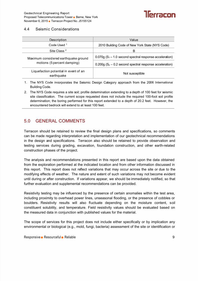
4.4 Seismic Considerations
Description Value
Code Used 1 2010 Building Code of New York State (NYS Code)
Site Class 2 B
Maximum considered earthquake ground
motions (5 percent damping)
0.070g (S1 – 1.0 second spectral response acceleration)
0.200g (Ss – 0.2 second spectral response acceleration)
Liquefaction potential in event of an
earthquakeNot susceptible
1. The NYS Code incorporates the Seismic Design Category approach from the 2006 International
Building Code.
2. The NYS Code requires a site soil; profile determination extending to a depth of 100 feet for seismic
site classification. The current scope requested does not include the required 100-foot soil profile
determination; the boring performed for this report extended to a depth of 20.2 feet. However, the
encountered bedrock will extend to at least 100 feet.
5.0 GENERAL COMMENTS
Terracon should be retained to review the final design plans and specifications, so comments
can be made regarding interpretation and implementation of our geotechnical recommendations
in the design and specifications. Terracon also should be retained to provide observation and
testing services during grading, excavation, foundation construction, and other earth-related
construction phases of the project.
The analysis and recommendations presented in this report are based upon the data obtained
from the exploration performed at the indicated location and from other information discussed in
this report. This report does not reflect variations that may occur across the site or due to the
modifying effects of weather. The nature and extent of such variations may not become evident
until during or after construction. If variations appear, we should be immediately notified, so that
further evaluation and supplemental recommendations can be provided.
Resistivity testing may be influenced by the presence of certain anomalies within the test area,
including proximity to overhead power lines, unseasonal flooding, or the presence of cobbles or
boulders. Resistivity results will also fluctuate depending on the moisture content, soil
constituent solubility, and temperature. Field resistivity values should be evaluated based on
the measured data in conjunction with published values for the material.
The scope of services for this project does not include either specifically or by implication any
environmental or biological (e.g., mold, fungi, bacteria) assessment of the site or identification or
8/20/2019 J5155124 Berne, NY Tower Geotechnical Report (Sealed) 11-6-15
http://slidepdf.com/reader/full/j5155124-berne-ny-tower-geotechnical-report-sealed-11-6-15 14/25
Geotechnical Engineering Report
Proposed Telecommunications Tower ■ Berne, New York
November 6, 2015 ■ Terracon Project No. J5155124
Responsive ■ Resourceful ■ Reliable 10
prevention of pollutants, hazardous materials or conditions. If the owner is concerned about the
potential for such contamination or pollution, other studies should be undertaken.
This report has been prepared for the exclusive use of our client for specific application to the
project discussed and prepared in accordance with generally accepted geotechnical engineeringpractices. No warranties, either express or implied, are intended or made. Site safety,
excavation support, and dewatering requirements are the responsibility of others. In the event
that changes in the nature, design, or location of the project as outlined in this report are
planned, the conclusions and recommendations contained in this report shall not be considered
valid unless Terracon reviews the changes and either verifies or modifies the conclusions of this
report in writing.

8/20/2019 J5155124 Berne, NY Tower Geotechnical Report (Sealed) 11-6-15
http://slidepdf.com/reader/full/j5155124-berne-ny-tower-geotechnical-report-sealed-11-6-15 15/25
APPENDIX A
FIELD EXPLORATION

8/20/2019 J5155124 Berne, NY Tower Geotechnical Report (Sealed) 11-6-15
http://slidepdf.com/reader/full/j5155124-berne-ny-tower-geotechnical-report-sealed-11-6-15 16/25
1 KILOMETER0.51
1 MILE
7000 FEET60005000400030002000100001000
01/21
NORTH AMERICAN VERTICAL DATUM OF 1988
CONTOU R INTERVAL 20 FEET
SCALE: 1:24 000
Project Mngr:CBR
Drawn By:
CBRChecked By:
RWM Approved By:
RWM
Project No.J5155124
Quadrangle:RENSSELAERVILLE,NY -2013
GALLUPVILLE,NY -2013
ALTAMONT, NY - 2013
WESTERLO, NY -2013
File No. J5155124.dwg
Date:
SITE LOCATION MAP EXHIB
A-
PROPOSED TELECOMMUNICATIONS TOWER28 JANSEN LANE
BERNE, NEW YORK
QUADRANGLE LOCATIO
OCTOBER 201515 Marway Circle, Suite 2BPH. (585 )247 3471
Rochester, NY 14624FAX.(585)363 7025
Consulting Engineers and Scientists

8/20/2019 J5155124 Berne, NY Tower Geotechnical Report (Sealed) 11-6-15
http://slidepdf.com/reader/full/j5155124-berne-ny-tower-geotechnical-report-sealed-11-6-15 17/25
Project Mngr:CBR
Drawn By:
CBRChecked By:
SCL
Approved By:RWM
Project No.J5155124
Scale:
1" = 16'
File No. J5155124.dwgDate:
EXPLORATION LOCATION DIAGRAM EXHIB
A-2
LEGEND
TEST BORING LOCATION
RESISTIVITY TEST LOCATION (TYP)
B-1
PROPOSED TELECOMMUNICATIONS TOWER28 JANSEN LANE
BERNE, NEW YORK
NOTES:
1. THIS DIAGRAM WAS PREPARED BASED ON A PLAN BY INFINIGY SOLUTIONS
LLC OF ALBANY, NEW YORK, , SHEET No. C3A, TITLED "OVERALL SITE PLAN
REVISED FEBRUARY 28, 2015.
2. THE TEST BORING B-1 WAS ADVANCED ON OCTOBER 21, 2015 UNDER TH
DIRECTION OF TERRACON WITH EQUIPMENT OWNED AND OPERATED BY
NORTHEAST SPECIALIZED DRILLING, INC. OF LIVERPOOL, NEW YORK.
3. RESIST IVITY TESTING WAS PERFORMED ON OCTOBER 21, 2015 BY A
TERRACON FIELD ENGINEER.
4. THE APPROXIMATE LOCATION OF THE EXPLORATION WAS STAKED BY
OTHERS PRIOR TO OUR ARRIVAL. RESISTIVITY TEST LOCATIONS WERE
MEASURED BY TAPING FROM EXISTING SITE FEATURES AND BY ESTIMATING
RIGHT ANGLES. THE LOCATIONS SHOULD BE CONSIDERED ACCURATE ONLY
TO THE DEGREE IMPLIED BY THE METHOD USED.
5. USE OF THIS DIAGRAM IS LIMITED TO THE ILLUSTRATION OF THE
APPROXIMATE LOCATIONS OF THE EXPLORATION, RESISTIVITY TESTING, AND
OTHER PERTINENT SITE FEATURES. ANY OTHER USE OF THIS DIAGRAM
WITHOUT PERMISSION FROM TERRACON IS PROHIBITED.
APPROXIMATE SCALE IN FEET
016 168
NOVEMBER 2015 15 Marway Circle, Suite 2BPH. (585)247 3471
Rochester, NY 14624FAX.(585)3 63 7025
Consulting Engineers and Scientists
LINE 1
L I N E
2
LINE 1
B-1
8/20/2019 J5155124 Berne, NY Tower Geotechnical Report (Sealed) 11-6-15
http://slidepdf.com/reader/full/j5155124-berne-ny-tower-geotechnical-report-sealed-11-6-15 18/25
Geotechnical Engineering Report
Proposed Telecommunications Tower ■ Berne, New York
November 6, 2015 ■ Terracon Project No. J5155124
Exhibit A-3
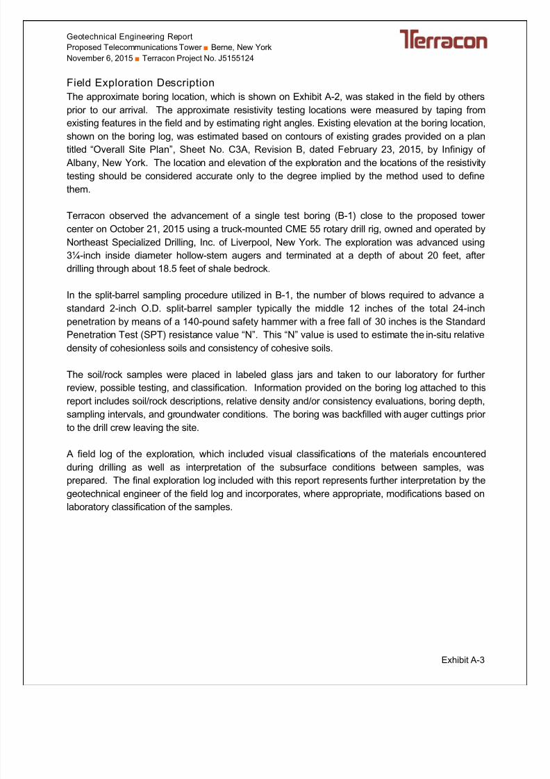
Field Exploration Description
The approximate boring location, which is shown on Exhibit A-2, was staked in the field by others
prior to our arrival. The approximate resistivity testing locations were measured by taping from
existing features in the field and by estimating right angles. Existing elevation at the boring location,
shown on the boring log, was estimated based on contours of existing grades provided on a plantitled “Overall Site Plan”, Sheet No. C3A, Revision B, dated February 23, 2015, by Infinigy of
Albany, New York. The location and elevation of the exploration and the locations of the resistivity
testing should be considered accurate only to the degree implied by the method used to define
them.
Terracon observed the advancement of a single test boring (B-1) close to the proposed tower
center on October 21, 2015 using a truck-mounted CME 55 rotary drill rig, owned and operated by
Northeast Specialized Drilling, Inc. of Liverpool, New York. The exploration was advanced using
3¼-inch inside diameter hollow-stem augers and terminated at a depth of about 20 feet, after
drilling through about 18.5 feet of shale bedrock.
In the split-barrel sampling procedure utilized in B-1, the number of blows required to advance a
standard 2-inch O.D. split-barrel sampler typically the middle 12 inches of the total 24-inch
penetration by means of a 140-pound safety hammer with a free fall of 30 inches is the Standard
Penetration Test (SPT) resistance value “N”. This “N” value is used to estimate the in-situ relative
density of cohesionless soils and consistency of cohesive soils.
The soil/rock samples were placed in labeled glass jars and taken to our laboratory for further
review, possible testing, and classification. Information provided on the boring log attached to this
report includes soil/rock descriptions, relative density and/or consistency evaluations, boring depth,
sampling intervals, and groundwater conditions. The boring was backfilled with auger cuttings prior
to the drill crew leaving the site.
A field log of the exploration, which included visual classifications of the materials encountered
during drilling as well as interpretation of the subsurface conditions between samples, was
prepared. The final exploration log included with this report represents further interpretation by the
geotechnical engineer of the field log and incorporates, where appropriate, modifications based on
laboratory classification of the samples.

8/20/2019 J5155124 Berne, NY Tower Geotechnical Report (Sealed) 11-6-15
http://slidepdf.com/reader/full/j5155124-berne-ny-tower-geotechnical-report-sealed-11-6-15 19/25
1448.5+/-
1447.5+/-
1429+/-
6
2
3
2
2
1
1
2-2-5-100/3"N=7
100/3"
100/4"
100/3"
100/3"
100/3"
100/2"
0.5
1.5
20.2
FOREST MAT
SILTY SAND (SM), with fragmented shale, brown, loose, (SUBSOIL)
SEDIMENTARY BEDROCK - SHALE, moderately weathered, weak, very thin bedding, gray,(BEDROCK)
Boring Terminated at 20.2 Feet
Stratification lines are approximate. In-situ, the transition may be gradual.
Samples taken with a 2" O.D. split spoon sampler driven by an auto-hammer operated by cathead.
G R A
P H I C L O G
T H I S B O R I N G L O G I S N O T V A L I D I F S E P A R A T E D F R O M O R I G I N A L R E P O R T .
G E O S M A R T L O G - N O W E L L
B E R N E . G P J
28 Jansen Lane Berne, New York
SITE:
Page 1 of 1
Advancement Method:3 1/4-inch inside diameter hollow stem auger
Abandonment Method:Boring backfilled with soil cuttings upon completion.
15 Marway Circle, Suite 2BRochester, New York
Notes:
Project No.: J5155124
Drill Rig: CME 55
Boring Started: 10/21/2015
BORING LOG NO. B-1
Pyramid Network Services LLCCLIENT:East Syracuse, New York
Driller: A. Linstruth
Boring Completed: 10/21/2015
Exhibit: A-4
See Exhibit A-3 for description of field procedures.
See Appendix B for description of laboratoryprocedures and additional data (if any).
See Appendix C for explanation of symbols andabbreviations.
PROJECT: Proposed Telecommunications Tower
Approximate Surface Elev: 1449 (Ft.) +/-
ELEVATION (Ft.) S
A M P L E T Y P E
W A T E R L E V E L
O B S E
R V A T I O N S
D E P T H ( F t . )
5
10
15
20
R E C O
V E R Y ( I n . )
F I E
L D T E S T
R E
S U L T S
DEPTH
LOCATION See Exhibit A-2
No free water observed
WATER LEVEL OBSERVATIONS

8/20/2019 J5155124 Berne, NY Tower Geotechnical Report (Sealed) 11-6-15
http://slidepdf.com/reader/full/j5155124-berne-ny-tower-geotechnical-report-sealed-11-6-15 20/25
APPENDIX B
LABORATORY TESTING

8/20/2019 J5155124 Berne, NY Tower Geotechnical Report (Sealed) 11-6-15
http://slidepdf.com/reader/full/j5155124-berne-ny-tower-geotechnical-report-sealed-11-6-15 21/25
Geotechnical Engineering Report
Proposed Telecommunications Tower ■ Berne, New York
November 6, 2015 ■ Terracon Project No. J5155124
Exhibit B-1
Laboratory Testing
Descriptive classifications of the soils indicated on the Terracon boring log are in accordance
with the enclosed General Notes and the Unified Soil Classification System (USCS). USCS
symbols are also shown. A brief description of the USCS is attached to this report.
Classification was by visual/manual procedures. A guide to bedrock classification, Description of Rock Properties, is also attached to this report.
8/20/2019 J5155124 Berne, NY Tower Geotechnical Report (Sealed) 11-6-15
http://slidepdf.com/reader/full/j5155124-berne-ny-tower-geotechnical-report-sealed-11-6-15 22/25
APPENDIX C
SUPPORTING DOCUMENTS

8/20/2019 J5155124 Berne, NY Tower Geotechnical Report (Sealed) 11-6-15
http://slidepdf.com/reader/full/j5155124-berne-ny-tower-geotechnical-report-sealed-11-6-15 23/25
TraceWithModifier
Water Level After a Specified Period of Time
GRAIN SIZE TERMINOLOGYRELATIVE PROPORTIONS OF SAND AND GRAVEL
TraceWithModifier
Standard Penetration or N-Value
Blows/Ft.
Descriptive Term(Consistency)
Loose
Very Stiff
Exhibit C-1
Standard Penetration or N-Value
Blows/Ft.
Ring Sampler Blows/Ft.
Ring Sampler Blows/Ft.
Medium Dense
Dense
Very Dense
0 - 1 < 3
4 - 9 2 - 4 3 - 4
Medium-Stiff 5 - 9
30 - 50
W A T E R
L E V E L
Auger
Shelby Tube
Ring Sampler
Grab Sample
8 - 15
Split Spoon
Macro Core
Rock Core
PLASTICITY DESCRIPTION
Term
< 1515 - 29> 30
Descriptive Term(s)of other constituents
Water InitiallyEncountered
Water Level After aSpecified Period of Time
Major Componentof Sample
Percent of Dry Weight
(More than 50% retained on No. 200 sieve.)Density determined by Standard Penetration Resistance
Includes gravels, sands and silts.
Hard
Very Loose 0 - 3 0 - 6 Very Soft
7 - 18 Soft
10 - 29 19 - 58
59 - 98 Stiff
less than 500
500 to 1,000
1,000 to 2,000
2,000 to 4,000
4,000 to 8,000> 99
LOCATION AND ELEVATION NOTES
S A M P L I N G
F I E L D T E S T S
(HP)
(T)
(b/f)
(PID)
(OVA)
DESCRIPTION OF SYMBOLS AND ABBREVIATIONS
Descriptive Term(Density)
Non-plasticLowMediumHigh
BouldersCobblesGravelSandSilt or Clay
10 - 18
> 50 15 - 30 19 - 42
> 30 > 42
_
Hand Penetrometer
Torvane
Standard PenetrationTest (blows per foot)
Photo-Ionization Detector
Organic Vapor Analyzer
Water levels indicated on the soil boring
logs are the levels measured in theborehole at the times indicated.Groundwater level variations will occur over time. In low permeability soils,accurate determination of groundwater levels is not possible with short termwater level observations.
CONSISTENCY OF FINE-GRAINED SOILS
(50% or more passing the No. 200 sieve.)Consistency determined by laboratory shear strength testing, field
visual-manual procedures or standard penetration resistance
DESCRIPTIVE SOIL CLASSIFICATION
> 8,000
Unless otherwise noted, Latitude and Longitude are approximately determined using a hand-held GPS device. The accuracyof such devices is variable. Surface elevation data annotated with +/- indicates that no actual topographical survey wasconducted to confirm the surface elevation. Instead, the surface elevation was approximately determined from topographicmaps of the area.
Soil classification is based on the Unified Soil Classification System. Coarse Grained Soils have more than 50% of their dryweight retained on a #200 sieve; their principal descriptors are: boulders, cobbles, gravel or sand. Fine Grained Soils haveless than 50% of their dry weight retained on a #200 sieve; they are principally described as clays if they are plastic, andsilts if they are slightly plastic or non-plastic. Major constituents may be added as modifiers and minor constituents may beadded according to the relative proportions based on grain size. In addition to gradation, coarse-grained soils are definedon the basis of their in-place relative density and fine-grained soils on the basis of their consistency.
Plasticity Index
01 - 1011 - 30
> 30
RELATIVE PROPORTIONS OF FINES
Descriptive Term(s)of other constituents
Percent of Dry Weight
< 55 - 12> 12
No Recovery
RELATIVE DENSITY OF COARSE-GRAINED SOILS
Particle Size
Over 12 in. (300 mm)12 in. to 3 in. (300mm to 75mm)3 in. to #4 sieve (75mm to 4.75 mm)#4 to #200 sieve (4.75mm to 0.075mmPassing #200 sieve (0.075mm)
S T R E N G T H T
E R M S Unconfined Compressive
Strength, Qu, psf
4 - 8
GENERAL NOTES

8/20/2019 J5155124 Berne, NY Tower Geotechnical Report (Sealed) 11-6-15
http://slidepdf.com/reader/full/j5155124-berne-ny-tower-geotechnical-report-sealed-11-6-15 24/25
UNIFIED SOIL CLASSIFICATION SYSTEM
Exhibit C-2
Criteria for Assigning Group Symbols and Group Names Using Laboratory Tests A
Soil Classification
Group
SymbolGroup Name
B
Coarse Grained Soil s:
More than 50% retained
on No. 200 sieve
Gravels:
More than 50% of
coarse fraction retained
on No. 4 sieve
Clean Gravels:
Less than 5% fines C
Cu 4 and 1 Cc 3 E
GW Well-graded gravelF
Cu 4 and/or 1 Cc 3 E
GP Poorly graded gravelF
Gravels with Fines:
More than 12% fines C
Fines classify as ML or MH GM Silty gravelF,G,H
Fines classify as CL or CH GC Clayey gravelF,G,H
Sands:
50% or more of coarse
fraction passes No. 4
sieve
Clean Sands:
Less than 5% fines D
Cu 6 and 1 Cc 3 E
SW Well-graded sandI
Cu 6 and/or 1 Cc 3 E SP Poorly graded sand I
Sands with Fines:
More than 12% fines D
Fines classify as ML or MH SM Silty sandG,H,I
Fines classify as CL or CH SC Clayey sandG,H,I
Fine-Grained Soil s:
50% or more passes the
No. 200 sieve
Silts and Clays:
Liquid limit less than 50
Inorganic:PI 7 and plots on or above “A” line
J CL Lean clay
K,L,M
PI 4 or plots below “A” line J ML Silt
K,L,M
Organic:Liquid limit - oven dried
0.75 OLOrganic clay
K,L,M,N
Liquid limit - not dried Organic siltK,L,M,O
Silts and Clays:
Liquid limit 50 or more
Inorganic:PI plots on or above “A” line CH Fat clay
K,L,M
PI plots below “A” line MH Elastic SiltK,L,M
Organic:Liquid limit - oven dried
0.75 OHOrganic clay
K,L,M,P
Liquid limit - not dried Organic siltK,L,M,Q
Highly organic soils: Primarily organic matter, dark in color, and organic odor PT Peat
ABased on the material passing the 3-inch (75-mm) sieve
BIf field sample contained cobbles or boulders, or both, add “with cobbles
or boulders, or both” to group name.C
Gravels with 5 to 12% fines require dual symbols: GW-GM well-graded
gravel with silt, GW-GC well-graded gravel with clay, GP-GM poorly
graded gravel with silt, GP-GC poorly graded gravel with clay.D
Sands with 5 to 12% fines require dual symbols: SW-SM well-graded
sand with silt, SW-SC well-graded sand with clay, SP-SM poorly graded
sand with silt, SP-SC poorly graded sand with clay
ECu = D60/D10 Cc =
6010
2
30
DxD
)(D
FIf soil contains 15% sand, add “with sand” to group name.
GIf fines classify as CL-ML, use dual symbol GC-GM, or SC-SM.
HIf fines are organic, add “with organic fines” to group name.
IIf soil contains 15% gravel, add “with gravel” to group name.
JIf Atterberg limits plot in shaded area, soil is a CL-ML, silty clay.
KIf soil contains 15 to 29% plus No. 200, add “with sand” or “with gravel,
whichever is predominant.L
If soil contains 30% plus No. 200 predominantly sand, add “sandy” to
group name.M
If soil contains 30% plus No. 200, predominantly gravel, add
“gravelly” to group name.N
PI 4 and plots on or above “A” line.O
PI 4 or plots below “A” line.P
PI plots on or above “A” line.Q
PI plots below “A” line.

8/20/2019 J5155124 Berne, NY Tower Geotechnical Report (Sealed) 11-6-15
http://slidepdf.com/reader/full/j5155124-berne-ny-tower-geotechnical-report-sealed-11-6-15 25/25
DESCRIPTION OF ROCK PROPERTIES
WEATHERING
Term Description
Unweathered No visible sign of rock material weathering, perhaps slight discoloration on major discontinuity surfaces.
Slightlyweathered
Discoloration indicates weathering of rock material and discontinuity surfaces. All the rock material may bediscolored by weathering and may be somewhat weaker externally than in its fresh condition.
Moderatelyweathered
Less than half of the rock material is decomposed and/or disintegrated to a soil. Fresh or discolored rock ispresent either as a continuous framework or as corestones.
Highlyweathered
More than half of the rock material is decomposed and/or disintegrated to a soil. Fresh or discolored rock ispresent either as a discontinuous framework or as corestones.
Completelyweathered
All rock material is decomposed and/or disintegrated to soil. The original mass structure is still largelyintact.
Residual soil All rock material is converted to soil. The mass structure and material fabric are destroyed. There is alarge change in volume, but the soil has not been significantly transported.
STRENGTH OR HARDNESS
Description Field IdentificationUniaxial CompressiveStrength, PSI (MPa)
Extremely weak Indented by thumbnail 40-150 (0.3-1)
Very weakCrumbles under firm blows with point of geological hammer, canbe peeled by a pocket knife
150-700 (1-5)
Weak rock Can be peeled by a pocket knife with difficulty, shallowindentations made by firm blow with point of geological hammer
700-4,000 (5-30)
Medium strongCannot be scraped or peeled with a pocket knife, specimen can befractured with single firm blow of geological hammer
4,000-7,000 (30-50)
Strong rockSpecimen requires more than one blow of geological hammer tofracture it
7,000-15,000 (50-100)
Very strong Specimen requires many blows of geological hammer to fracture it 15,000-36,000 (100-250)
Extremely strong Specimen can only be chipped with geological hammer >36,000 (>250)
DISCONTINUITY DESCRIPTION
Fracture Spacing (Joints, Faults, Other Fractures) Bedding Spacing (May Include Foliation or Banding )
Description Spacing Description Spacing
Extremely close < ¾ in (<19 mm) Laminated < ½ in (<12 mm)
Very close ¾ in – 2-1/2 in (19 - 60 mm) Very th in ½ in – 2 in (12 – 50 mm)Close 2-1/2 in – 8 in (60 – 200 mm) Thin 2 in – 1 ft (50 – 300 mm)
Moderate 8 in – 2 ft (200 – 600 mm) Medium 1 ft – 3 ft (300 – 900 mm)
Wide 2 ft – 6 ft (600 mm – 2.0 m) Thick 3 ft – 10 ft (900 mm – 3 m)
Very Wide 6 ft – 20 ft (2.0 – 6 m) Massive > 10 ft (3 m)
Discontinuity Orientation (Angle): Measure the angle of discontinuity relative to a plane perpendicular to the longitudinal axis ofthe core. (For most cases, the core axis is vertical; therefore, the plane perpendicular to the core axis is horizontal.) Forexample, a horizontal bedding plane would have a 0 degree angle.
ROCK QUALITY DESIGNATION (RQD*)
Descripti on RQD Value (%)
Very Poor 0 - 25
Poor 25 – 50
Fair 50 – 75
Good 75 – 90
Excellent 90 - 100
*The combined length of all sound and intact core segments equal to or greater than 4 inches in length, expressed as apercentage of the total core run length.
Reference: U.S. Department of Transportation, Federal Highway Administration, Publication No FHWA-NHI-10-034, December 2009
Technical Manual for Design and Construction of Road Tunnels – Civil Elements


![[Eric Berne] Sex in Human Loving(BookFi.org)](https://img.pdfslide.us/doc/110x75/5695d0321a28ab9b02916659/eric-berne-sex-in-human-lovingbookfiorg.jpg)