Embed Size (px)
Citation preview
COMMON RAIL SYSTEM (CRS)SERVICE MANUAL: Operation
J05D/J08E Engine
Issued : September 2007Revised : May 2010
00400041EB
© 2010 DENSO CORPORATIONAll rights reserved. This material may not be reproduced or copied, in whole or in part, without the written permission of DENSO Corporation.
Revision HistoryDate Revision Contents
2007.09 • Basic CRS content omitted, March 2007 model CRS content added. Items addedare as per the following:
Applicable Vehicles and Product InformationMain Components and SensorsExhaust Gas Control System (DPF System)Engine ECU Diagnostic Trouble Codes (DTC)Engine ECU External Wiring Diagram and Connector Terminal Layout
2010.05 • March 2010 model CRS content added. Items added are as per the following:Applicable Vehicles and Product InformationCRS Outline (Diagram)Supply PumpRailInjectorEngine ECUSelective Catalytic Reduction (SCR) SystemEngine ECU Diagnostic Trouble Codes (DTC)Engine ECU External Wiring Diagrams and Connector Terminal Layout
Table of Contents
Operation Section
1. APPLICABLE VEHICLE AND PRODUCT INFORMATION1.1 Introduction . . . . . . . . . . . . . . . . . . . . . . . . . . . . . . . . . . . . . . . . . . . . . . . . . . . . . . . . . . . . . . . . . . . . . . . . . . . . 1-1
1.2 Applicable Vehicles . . . . . . . . . . . . . . . . . . . . . . . . . . . . . . . . . . . . . . . . . . . . . . . . . . . . . . . . . . . . . . . . . . . . . . 1-1
1.3 Applicable Products List . . . . . . . . . . . . . . . . . . . . . . . . . . . . . . . . . . . . . . . . . . . . . . . . . . . . . . . . . . . . . . . . . . 1-2
2. COMMON RAIL SYSTEM (CRS) OUTLINE2.1 CRS Outline (Diagram) . . . . . . . . . . . . . . . . . . . . . . . . . . . . . . . . . . . . . . . . . . . . . . . . . . . . . . . . . . . . . . . . . . . 1-4
3. SUPPLY PUMP3.1 Outline . . . . . . . . . . . . . . . . . . . . . . . . . . . . . . . . . . . . . . . . . . . . . . . . . . . . . . . . . . . . . . . . . . . . . . . . . . . . . . . . 1-6
3.2 Suction Control Valve (SCV) . . . . . . . . . . . . . . . . . . . . . . . . . . . . . . . . . . . . . . . . . . . . . . . . . . . . . . . . . . . . . . . 1-8
3.3 Fuel Temperature Sensor . . . . . . . . . . . . . . . . . . . . . . . . . . . . . . . . . . . . . . . . . . . . . . . . . . . . . . . . . . . . . . . . 1-10
4. RAIL4.1 Outline . . . . . . . . . . . . . . . . . . . . . . . . . . . . . . . . . . . . . . . . . . . . . . . . . . . . . . . . . . . . . . . . . . . . . . . . . . . . . . . 1-11
5. INJECTOR5.1 Outline . . . . . . . . . . . . . . . . . . . . . . . . . . . . . . . . . . . . . . . . . . . . . . . . . . . . . . . . . . . . . . . . . . . . . . . . . . . . . . . 1-14
6. CONTROL SYSTEM6.1 Engine ECU. . . . . . . . . . . . . . . . . . . . . . . . . . . . . . . . . . . . . . . . . . . . . . . . . . . . . . . . . . . . . . . . . . . . . . . . . . . 1-18
6.2 Sensors . . . . . . . . . . . . . . . . . . . . . . . . . . . . . . . . . . . . . . . . . . . . . . . . . . . . . . . . . . . . . . . . . . . . . . . . . . . . . . 1-20
7. EXHAUST GAS CONTROL SYSTEM7.1 Exhaust Gas Recirculation (EGR) System (2004 Model Only) . . . . . . . . . . . . . . . . . . . . . . . . . . . . . . . . . . . . 1-26
7.2 Diesel Particulate Filter (DPF) System (2007, 2010 Model) . . . . . . . . . . . . . . . . . . . . . . . . . . . . . . . . . . . . . . 1-27
7.3 Selective Catalytic Reduction (SCR) System (2010 Model Only) . . . . . . . . . . . . . . . . . . . . . . . . . . . . . . . . . . 1-29
8. ENGINE ECU DIAGNOSTIC TROUBLE CODES (DTC)8.1 DTC Table . . . . . . . . . . . . . . . . . . . . . . . . . . . . . . . . . . . . . . . . . . . . . . . . . . . . . . . . . . . . . . . . . . . . . . . . . . . . 1-30
9. ATTACHED MATERIALS9.1 Engine ECU External Wiring Diagrams . . . . . . . . . . . . . . . . . . . . . . . . . . . . . . . . . . . . . . . . . . . . . . . . . . . . . . 1-45
9.2 Connector Terminal Layout . . . . . . . . . . . . . . . . . . . . . . . . . . . . . . . . . . . . . . . . . . . . . . . . . . . . . . . . . . . . . . . 1-49
Operation Section1–1
1. APPLICABLE VEHICLE AND PRODUCT INFORMATION
1.1 Introduction
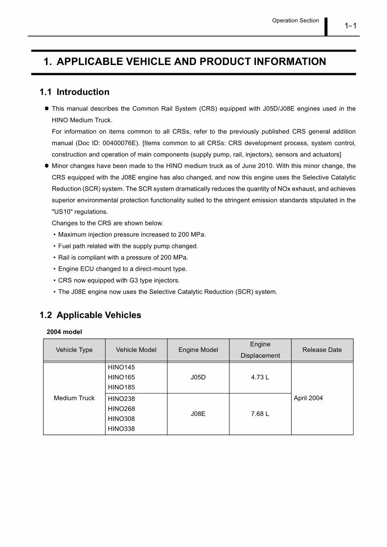
This manual describes the Common Rail System (CRS) equipped with J05D/J08E engines used in the
HINO Medium Truck.
For information on items common to all CRSs, refer to the previously published CRS general addition
manual (Doc ID: 00400076E). [Items common to all CRSs: CRS development process, system control,
construction and operation of main components (supply pump, rail, injectors), sensors and actuators]
Minor changes have been made to the HINO medium truck as of June 2010. With this minor change, the
CRS equipped with the J08E engine has also changed, and now this engine uses the Selective Catalytic
Reduction (SCR) system. The SCR system dramatically reduces the quantity of NOx exhaust, and achieves
superior environmental protection functionality suited to the stringent emission standards stipulated in the
"US10" regulations.
Changes to the CRS are shown below.
• Maximum injection pressure increased to 200 MPa.
• Fuel path related with the supply pump changed.
• Rail is compliant with a pressure of 200 MPa.
• Engine ECU changed to a direct-mount type.
• CRS now equipped with G3 type injectors.
• The J08E engine now uses the Selective Catalytic Reduction (SCR) system.
1.2 Applicable Vehicles
2004 model
Vehicle Type Vehicle Model Engine ModelEngine
DisplacementRelease Date
Medium Truck
HINO145HINO165HINO185
J05D 4.73 L
April 2004HINO238 HINO268 HINO308HINO338
J08E 7.68 L
Operation Section1–2
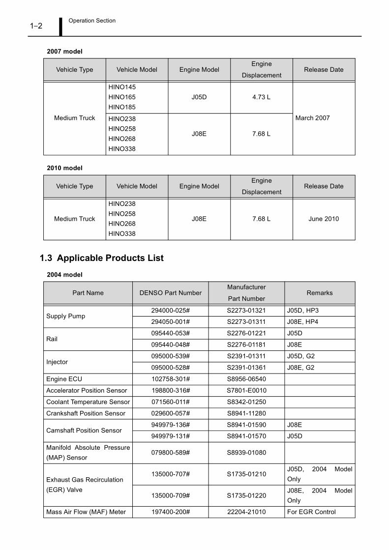
2007 model
2010 model
1.3 Applicable Products List
2004 model
Vehicle Type Vehicle Model Engine ModelEngine
DisplacementRelease Date
Medium Truck
HINO145 HINO165HINO185
J05D 4.73 L
March 2007HINO238 HINO258 HINO268HINO338
J08E 7.68 L
Vehicle Type Vehicle Model Engine ModelEngine
DisplacementRelease Date
Medium Truck
HINO238HINO258HINO268HINO338
J08E 7.68 L June 2010
Part Name DENSO Part NumberManufacturer
Part NumberRemarks
Supply Pump294000-025# S2273-01321 J05D, HP3
294050-001# S2273-01311 J08E, HP4
Rail095440-053# S2276-01221 J05D
095440-048# S2276-01181 J08E
Injector095000-539# S2391-01311 J05D, G2
095000-528# S2391-01361 J08E, G2
Engine ECU 102758-301# S8956-06540
Accelerator Position Sensor 198800-316# S7801-E0010
Coolant Temperature Sensor 071560-011# S8342-01250
Crankshaft Position Sensor 029600-057# S8941-11280
Camshaft Position Sensor949979-136# S8941-01590 J08E
949979-131# S8941-01570 J05D
Manifold Absolute Pressure(MAP) Sensor
079800-589# S8939-01080
Exhaust Gas Recirculation (EGR) Valve
135000-707# S1735-01210J05D, 2004 ModelOnly
135000-709# S1735-01220J08E, 2004 ModelOnly
Mass Air Flow (MAF) Meter 197400-200# 22204-21010 For EGR Control
Operation Section1–3
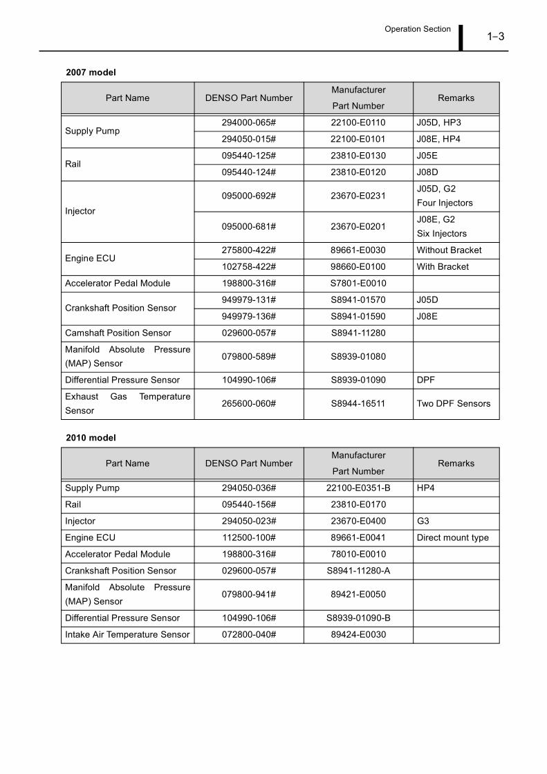
2007 model
2010 model
Part Name DENSO Part NumberManufacturer
Part NumberRemarks
Supply Pump294000-065# 22100-E0110 J05D, HP3
294050-015# 22100-E0101 J08E, HP4
Rail095440-125# 23810-E0130 J05E
095440-124# 23810-E0120 J08D
Injector
095000-692# 23670-E0231J05D, G2Four Injectors
095000-681# 23670-E0201J08E, G2Six Injectors
Engine ECU275800-422# 89661-E0030 Without Bracket
102758-422# 98660-E0100 With Bracket
Accelerator Pedal Module 198800-316# S7801-E0010
Crankshaft Position Sensor949979-131# S8941-01570 J05D
949979-136# S8941-01590 J08E
Camshaft Position Sensor 029600-057# S8941-11280
Manifold Absolute Pressure(MAP) Sensor
079800-589# S8939-01080
Differential Pressure Sensor 104990-106# S8939-01090 DPF
Exhaust Gas TemperatureSensor
265600-060# S8944-16511 Two DPF Sensors
Part Name DENSO Part NumberManufacturer
Part NumberRemarks
Supply Pump 294050-036# 22100-E0351-B HP4
Rail 095440-156# 23810-E0170
Injector 294050-023# 23670-E0400 G3
Engine ECU 112500-100# 89661-E0041 Direct mount type
Accelerator Pedal Module 198800-316# 78010-E0010
Crankshaft Position Sensor 029600-057# S8941-11280-A
Manifold Absolute Pressure(MAP) Sensor
079800-941# 89421-E0050
Differential Pressure Sensor 104990-106# S8939-01090-B
Intake Air Temperature Sensor 072800-040# 89424-E0030
Operation Section1–4
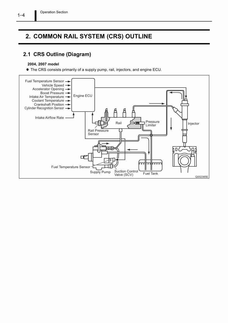
2. COMMON RAIL SYSTEM (CRS) OUTLINE
2.1 CRS Outline (Diagram)
2004, 2007 modelThe CRS consists primarily of a supply pump, rail, injectors, and engine ECU.
Operation Section1–5
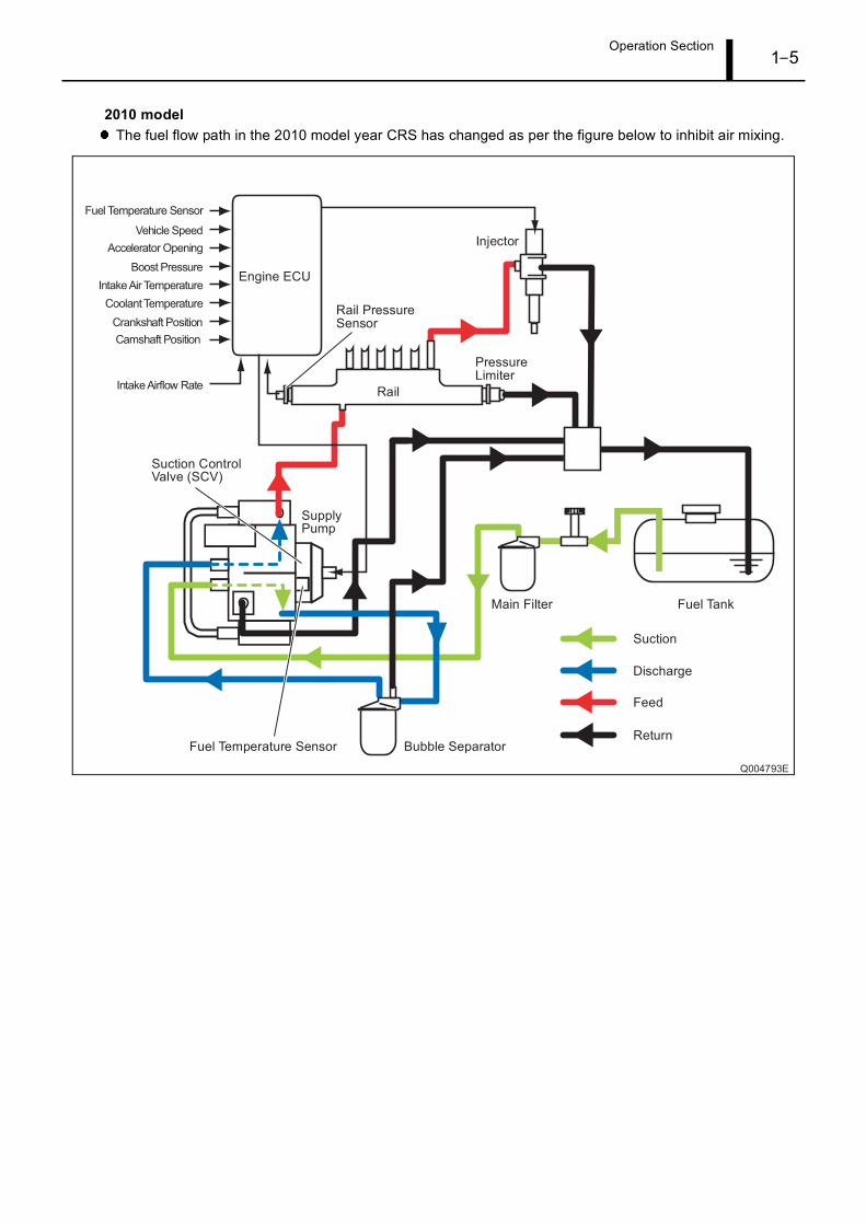
2010 modelThe fuel flow path in the 2010 model year CRS has changed as per the figure below to inhibit air mixing.
Operation Section1–6
3. SUPPLY PUMP
3.1 Outline
The HP3 and HP4 supply pumps have the same construction and operational characteristics as the
conventional supply pumps. Supply pumps place fuel suctioned from the fuel tank under high pressure for
delivery to the rail.
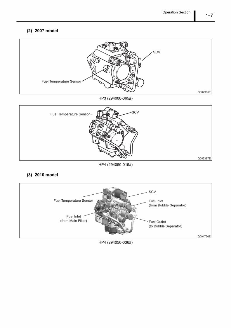
A feed pump outlet, and pump inlet have been added to the 2010 model supply pump to inhibit air mixing.
As a result of this change, the fuel flow has been altered to travel through the following path: main filter, feed
pump, bubble separator, pump unit.
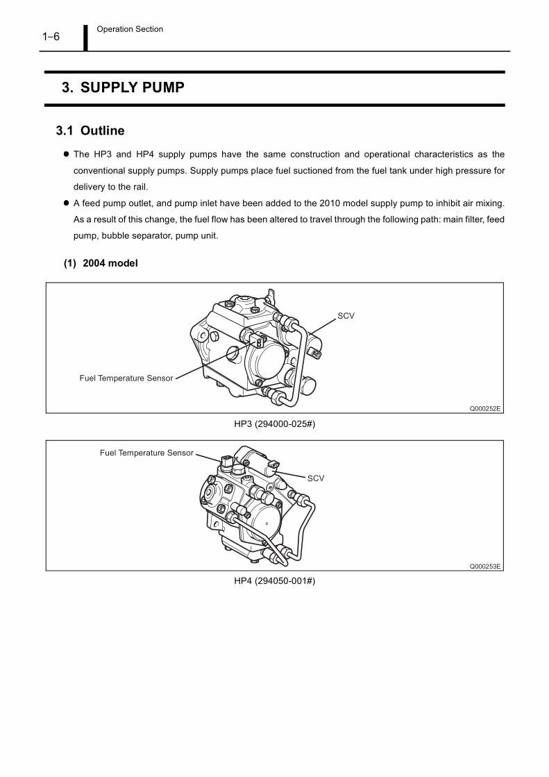
(1) 2004 model
HP3 (294000-025#)
HP4 (294050-001#)
Operation Section1–7
(2) 2007 model
HP3 (294000-065#)
HP4 (294050-015#)
(3) 2010 model
HP4 (294050-036#)
Operation Section1–8
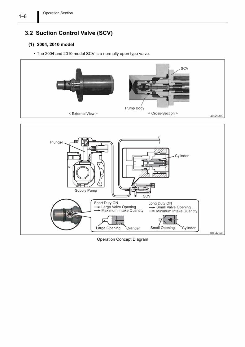
3.2 Suction Control Valve (SCV)
(1) 2004, 2010 model
• The 2004 and 2010 model SCV is a normally open type valve.
Operation Concept Diagram
Operation Section1–9
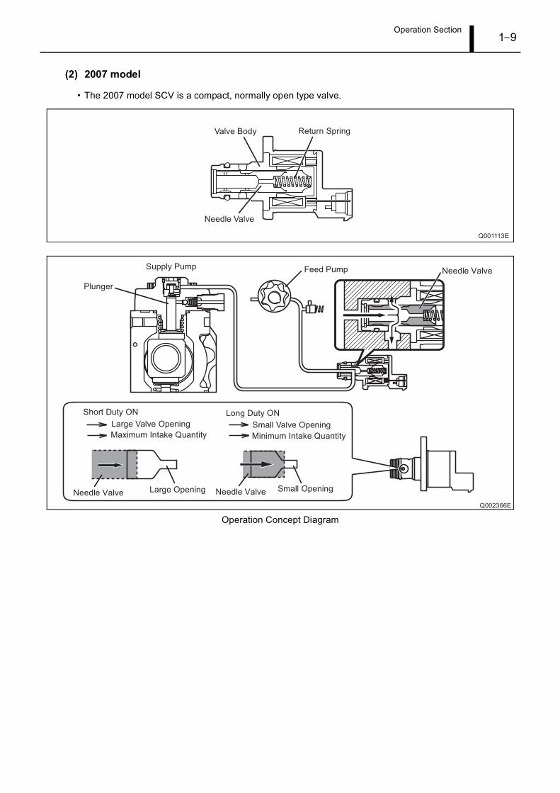
(2) 2007 model
• The 2007 model SCV is a compact, normally open type valve.
Operation Concept Diagram
Operation Section1–10
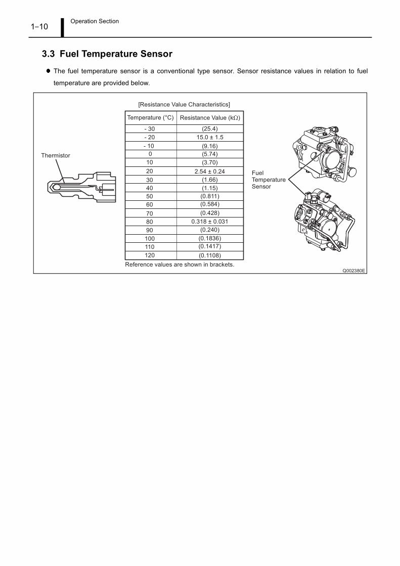
3.3 Fuel Temperature Sensor
The fuel temperature sensor is a conventional type sensor. Sensor resistance values in relation to fuel
temperature are provided below.
Operation Section1–11
4. RAIL
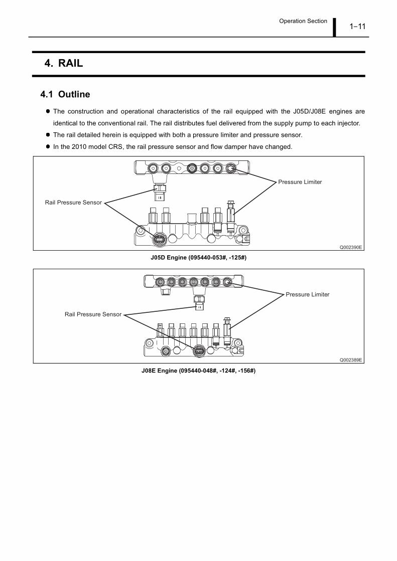
4.1 Outline
The construction and operational characteristics of the rail equipped with the J05D/J08E engines are
identical to the conventional rail. The rail distributes fuel delivered from the supply pump to each injector.
The rail detailed herein is equipped with both a pressure limiter and pressure sensor.
In the 2010 model CRS, the rail pressure sensor and flow damper have changed.
J05D Engine (095440-053#, -125#)
J08E Engine (095440-048#, -124#, -156#)
Operation Section1–12
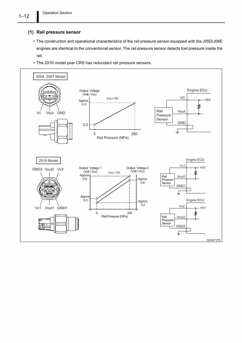
(1) Rail pressure sensor
• The construction and operational characteristics of the rail pressure sensor equipped with the J05D/J08E
engines are identical to the conventional sensor. The rail pressure sensor detects fuel pressure inside the
rail.
• The 2010 model year CRS has redundant rail pressure sensors.
Operation Section1–13
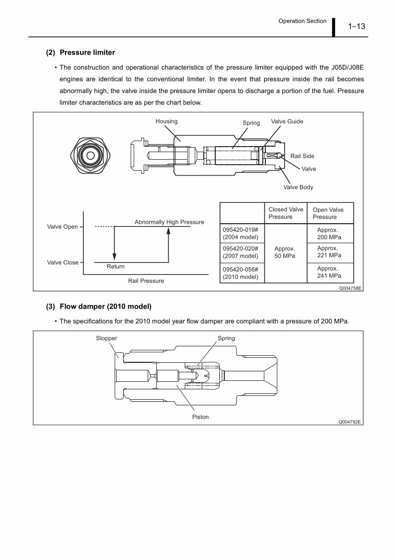
(2) Pressure limiter
• The construction and operational characteristics of the pressure limiter equipped with the J05D/J08E
engines are identical to the conventional limiter. In the event that pressure inside the rail becomes
abnormally high, the valve inside the pressure limiter opens to discharge a portion of the fuel. Pressure
limiter characteristics are as per the chart below.
(3) Flow damper (2010 model)
• The specifications for the 2010 model year flow damper are compliant with a pressure of 200 MPa.
Operation Section1–14
5. INJECTOR
5.1 Outline
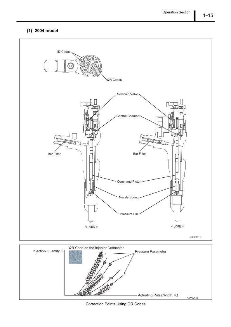
The 2004 and 2007 model year CRSs use G2 injectors. The construction and operational characteristics of
the G2 injectors are identical to the conventional injector. The G2 injector injects fuel into the engine
combustion chamber in accordance with signals from the engine ECU.
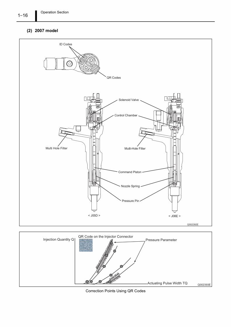
As of the 2007 model year CRS, the injectors use a mutli-hole filter.
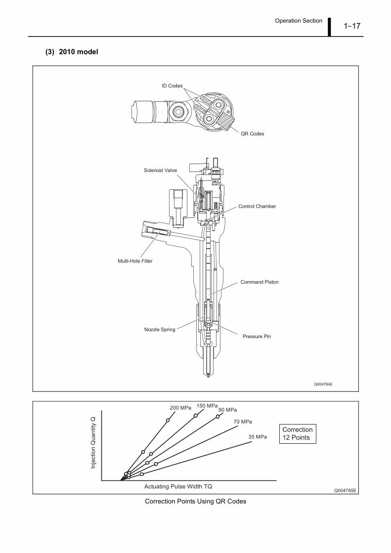
The 2010 model year CRS uses G3 injectors. G3 injectors are compliant with a pressure of 200 MPa, and
show improved responsiveness, as well as an increased resistance to foreign material adherence.
Operation Section1–15
(1) 2004 model
Correction Points Using QR Codes
Operation Section1–16
(2) 2007 model
Correction Points Using QR Codes
Operation Section1–17
(3) 2010 model
Correction Points Using QR Codes
Operation Section1–18
6. CONTROL SYSTEM
6.1 Engine ECU
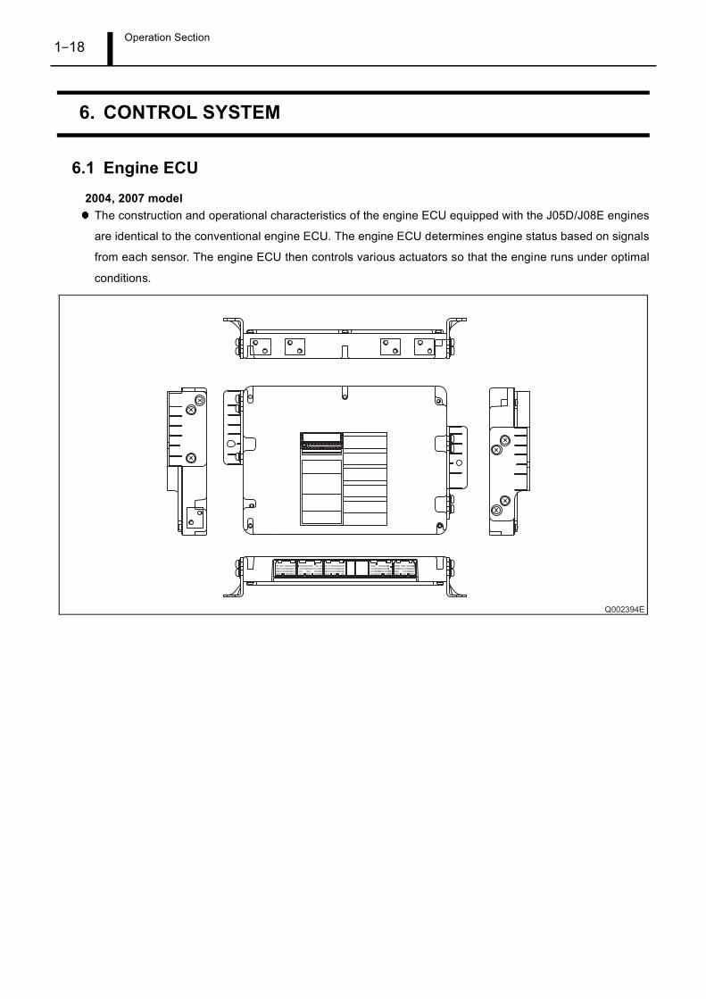
2004, 2007 modelThe construction and operational characteristics of the engine ECU equipped with the J05D/J08E engines
are identical to the conventional engine ECU. The engine ECU determines engine status based on signals
from each sensor. The engine ECU then controls various actuators so that the engine runs under optimal
conditions.
Operation Section1–19
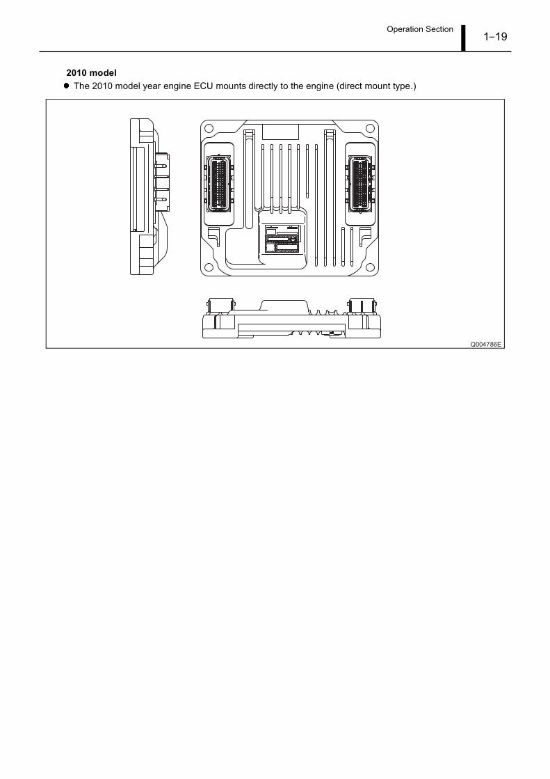
2010 modelThe 2010 model year engine ECU mounts directly to the engine (direct mount type.)
Operation Section1–20
6.2 Sensors
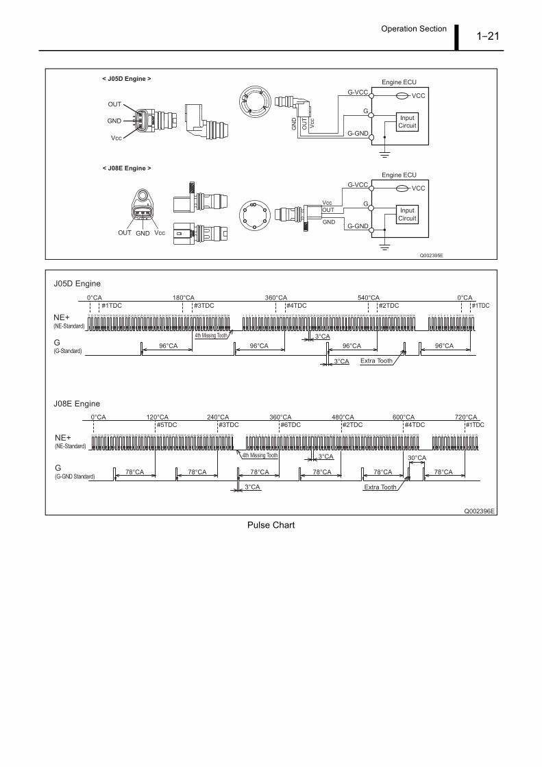
(1) Crankshaft position sensor and camshaft position sensor
• The construction and operational characteristics of both the crankshaft position sensor and camshaft
position sensor equipped with the J05D/J08E engines are identical to the conventional sensors.
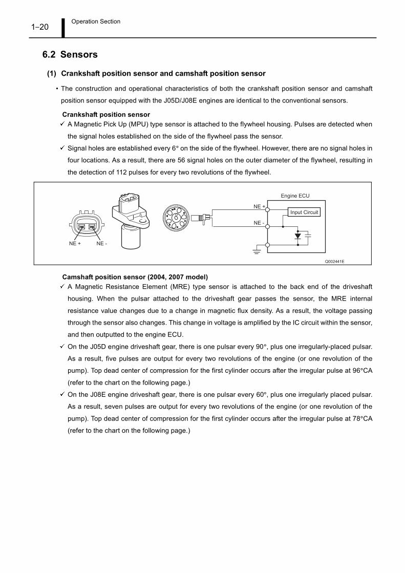
Crankshaft position sensorA Magnetic Pick Up (MPU) type sensor is attached to the flywheel housing. Pulses are detected when
the signal holes established on the side of the flywheel pass the sensor.
Signal holes are established every 6° on the side of the flywheel. However, there are no signal holes in
four locations. As a result, there are 56 signal holes on the outer diameter of the flywheel, resulting in
the detection of 112 pulses for every two revolutions of the flywheel.
Camshaft position sensor (2004, 2007 model)A Magnetic Resistance Element (MRE) type sensor is attached to the back end of the driveshaft
housing. When the pulsar attached to the driveshaft gear passes the sensor, the MRE internal
resistance value changes due to a change in magnetic flux density. As a result, the voltage passing
through the sensor also changes. This change in voltage is amplified by the IC circuit within the sensor,
and then outputted to the engine ECU.
On the J05D engine driveshaft gear, there is one pulsar every 90°, plus one irregularly-placed pulsar.
As a result, five pulses are output for every two revolutions of the engine (or one revolution of the
pump). Top dead center of compression for the first cylinder occurs after the irregular pulse at 96°CA
(refer to the chart on the following page.)
On the J08E engine driveshaft gear, there is one pulsar every 60°, plus one irregularly placed pulsar.
As a result, seven pulses are output for every two revolutions of the engine (or one revolution of the
pump). Top dead center of compression for the first cylinder occurs after the irregular pulse at 78°CA
(refer to the chart on the following page.)
Operation Section1–21
Pulse Chart
Operation Section1–22
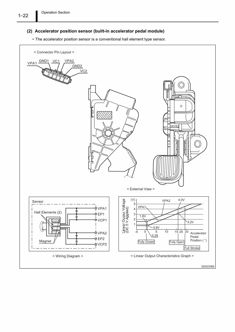
(2) Accelerator position sensor (built-in accelerator pedal module)
• The accelerator position sensor is a conventional hall element type sensor.
Operation Section1–23
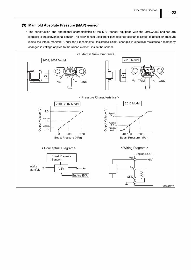
(3) Manifold Absolute Pressure (MAP) sensor
• The construction and operational characteristics of the MAP sensor equipped with the J05D/J08E engines are
identical to the conventional sensor. The MAP sensor uses the "Piezoelectric Resistance Effect" to detect air pressure
inside the intake manifold. Under the Piezoelectric Resistance Effect, changes in electrical resistance accompany
changes in voltage applied to the silicon element inside the sensor.
Operation Section1–24
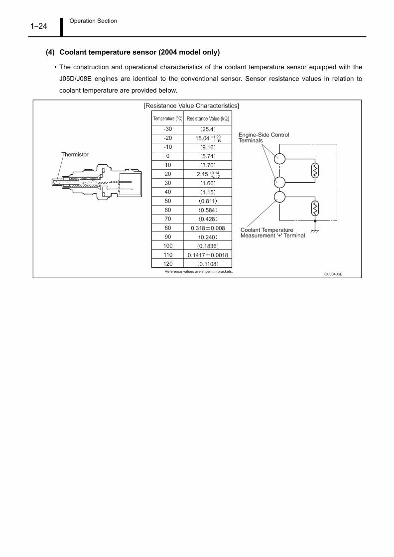
(4) Coolant temperature sensor (2004 model only)
• The construction and operational characteristics of the coolant temperature sensor equipped with the
J05D/J08E engines are identical to the conventional sensor. Sensor resistance values in relation to
coolant temperature are provided below.
Operation Section1–25
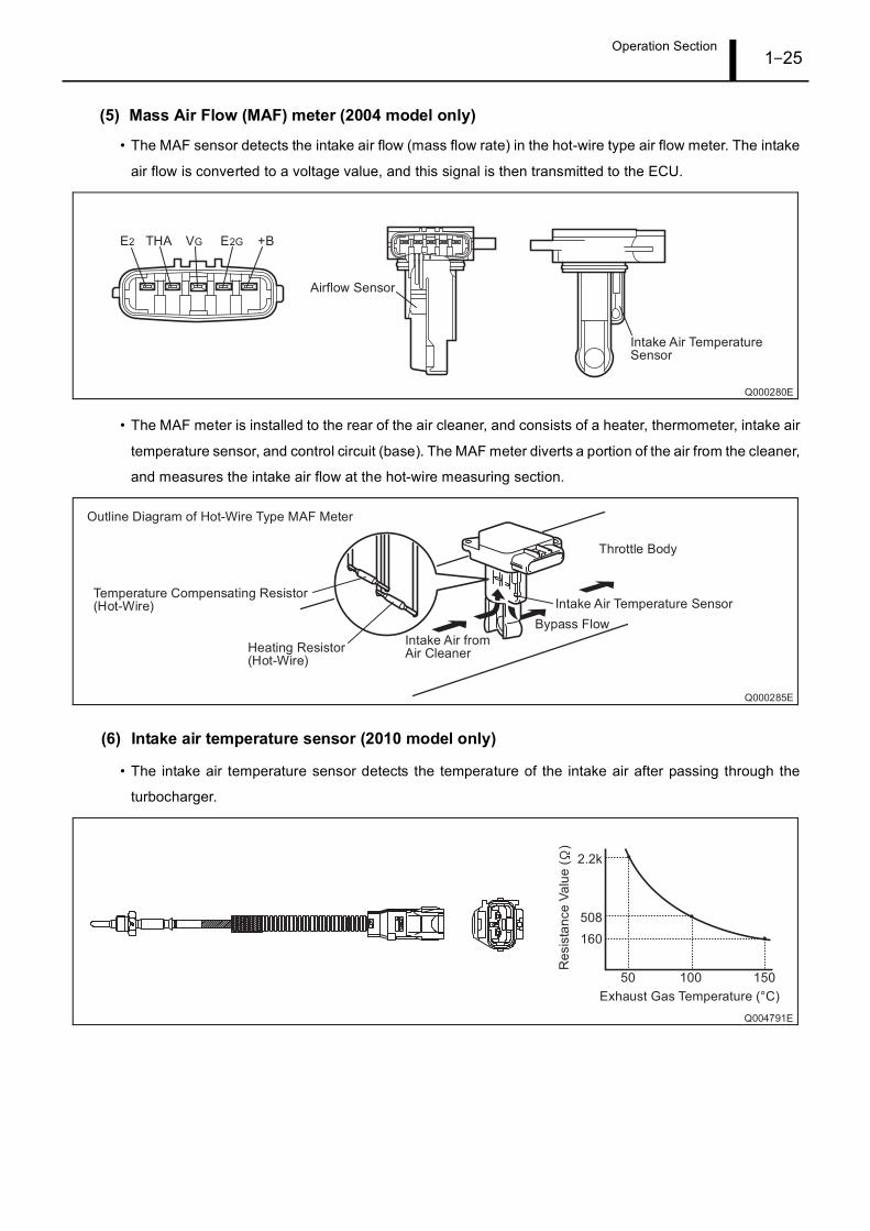
(5) Mass Air Flow (MAF) meter (2004 model only)
• The MAF sensor detects the intake air flow (mass flow rate) in the hot-wire type air flow meter. The intake
air flow is converted to a voltage value, and this signal is then transmitted to the ECU.
• The MAF meter is installed to the rear of the air cleaner, and consists of a heater, thermometer, intake air
temperature sensor, and control circuit (base). The MAF meter diverts a portion of the air from the cleaner,
and measures the intake air flow at the hot-wire measuring section.
(6) Intake air temperature sensor (2010 model only)
• The intake air temperature sensor detects the temperature of the intake air after passing through the
turbocharger.
Operation Section1–26
7. EXHAUST GAS CONTROL SYSTEM
7.1 Exhaust Gas Recirculation (EGR) System (2004 Model Only)
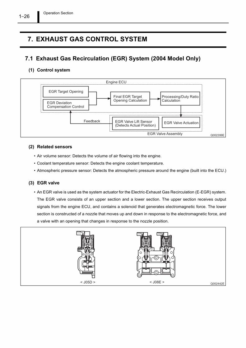
(1) Control system
(2) Related sensors
• Air volume sensor: Detects the volume of air flowing into the engine.
• Coolant temperature sensor: Detects the engine coolant temperature.
• Atmospheric pressure sensor: Detects the atmospheric pressure around the engine (built into the ECU.)
(3) EGR valve
• An EGR valve is used as the system actuator for the Electric-Exhaust Gas Recirculation (E-EGR) system.
The EGR valve consists of an upper section and a lower section. The upper section receives output
signals from the engine ECU, and contains a solenoid that generates electromagnetic force. The lower
section is constructed of a nozzle that moves up and down in response to the electromagnetic force, and
a valve with an opening that changes in response to the nozzle position.
Operation Section1–27
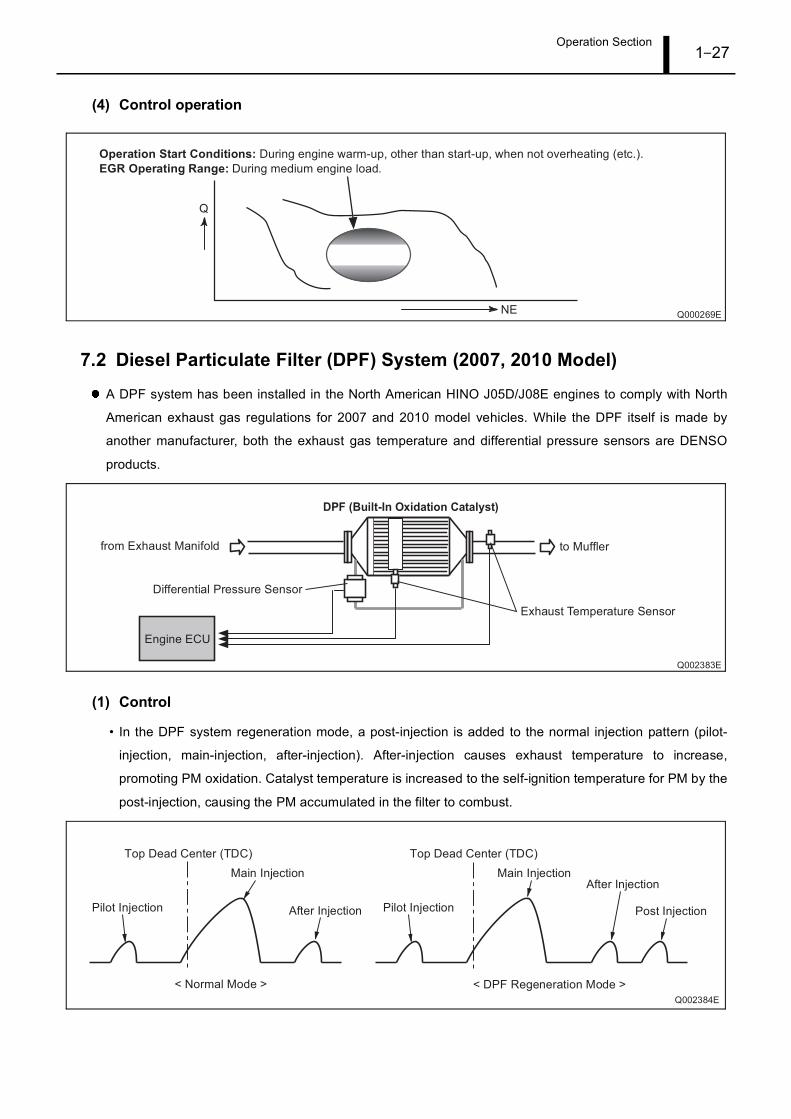
(4) Control operation
7.2 Diesel Particulate Filter (DPF) System (2007, 2010 Model)
A DPF system has been installed in the North American HINO J05D/J08E engines to comply with North
American exhaust gas regulations for 2007 and 2010 model vehicles. While the DPF itself is made by
another manufacturer, both the exhaust gas temperature and differential pressure sensors are DENSO
products.
(1) Control
• In the DPF system regeneration mode, a post-injection is added to the normal injection pattern (pilot-
injection, main-injection, after-injection). After-injection causes exhaust temperature to increase,
promoting PM oxidation. Catalyst temperature is increased to the self-ignition temperature for PM by the
post-injection, causing the PM accumulated in the filter to combust.
Operation Section1–28
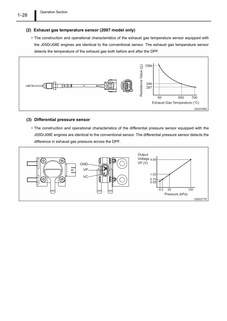
(2) Exhaust gas temperature sensor (2007 model only)
• The construction and operational characteristics of the exhaust gas temperature sensor equipped with
the J05D/J08E engines are identical to the conventional sensor. The exhaust gas temperature sensor
detects the temperature of the exhaust gas both before and after the DPF.
(3) Differential pressure sensor
• The construction and operational characteristics of the differential pressure sensor equipped with the
J05D/J08E engines are identical to the conventional sensor. The differential pressure sensor detects the
difference in exhaust gas pressure across the DPF.
Operation Section1–29
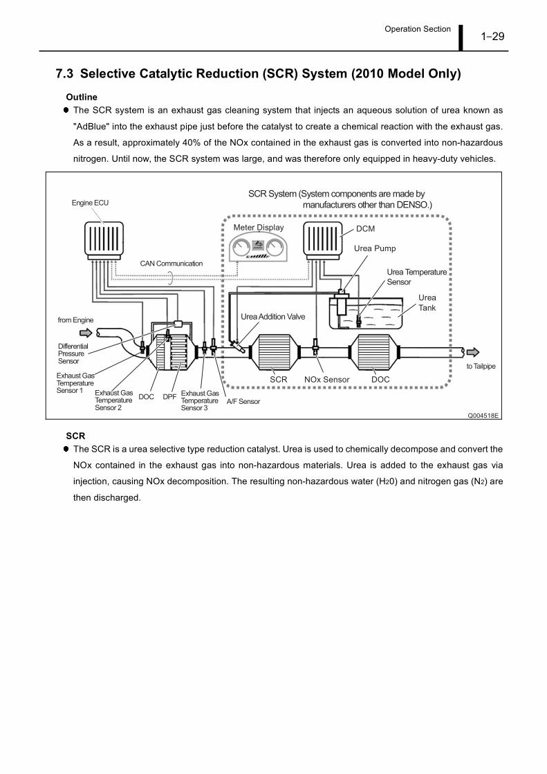
7.3 Selective Catalytic Reduction (SCR) System (2010 Model Only)
OutlineThe SCR system is an exhaust gas cleaning system that injects an aqueous solution of urea known as
"AdBlue" into the exhaust pipe just before the catalyst to create a chemical reaction with the exhaust gas.
As a result, approximately 40% of the NOx contained in the exhaust gas is converted into non-hazardous
nitrogen. Until now, the SCR system was large, and was therefore only equipped in heavy-duty vehicles.
SCRThe SCR is a urea selective type reduction catalyst. Urea is used to chemically decompose and convert the
NOx contained in the exhaust gas into non-hazardous materials. Urea is added to the exhaust gas via
injection, causing NOx decomposition. The resulting non-hazardous water (H20) and nitrogen gas (N2) are
then discharged.
Operation Section1–30
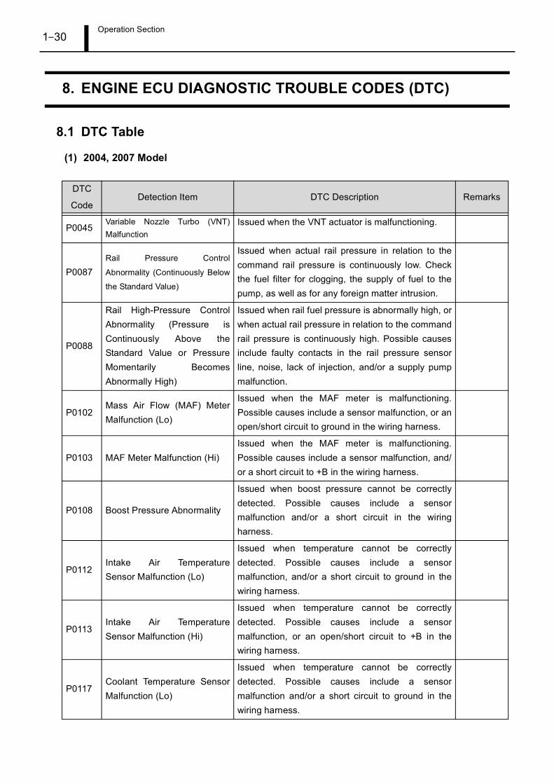
8. ENGINE ECU DIAGNOSTIC TROUBLE CODES (DTC)
8.1 DTC Table
(1) 2004, 2007 Model
DTC
CodeDetection Item DTC Description Remarks
P0045Variable Nozzle Turbo (VNT)Malfunction
Issued when the VNT actuator is malfunctioning.
P0087Rail Pressure Control
Abnormality (Continuously Below
the Standard Value)
Issued when actual rail pressure in relation to thecommand rail pressure is continuously low. Checkthe fuel filter for clogging, the supply of fuel to thepump, as well as for any foreign matter intrusion.
P0088
Rail High-Pressure ControlAbnormality (Pressure isContinuously Above theStandard Value or PressureMomentarily BecomesAbnormally High)
Issued when rail fuel pressure is abnormally high, orwhen actual rail pressure in relation to the commandrail pressure is continuously high. Possible causesinclude faulty contacts in the rail pressure sensorline, noise, lack of injection, and/or a supply pumpmalfunction.
P0102Mass Air Flow (MAF) MeterMalfunction (Lo)
Issued when the MAF meter is malfunctioning.Possible causes include a sensor malfunction, or anopen/short circuit to ground in the wiring harness.
P0103 MAF Meter Malfunction (Hi)Issued when the MAF meter is malfunctioning.Possible causes include a sensor malfunction, and/or a short circuit to +B in the wiring harness.
P0108 Boost Pressure Abnormality
Issued when boost pressure cannot be correctlydetected. Possible causes include a sensormalfunction and/or a short circuit in the wiringharness.
P0112Intake Air TemperatureSensor Malfunction (Lo)
Issued when temperature cannot be correctlydetected. Possible causes include a sensormalfunction, and/or a short circuit to ground in thewiring harness.
P0113Intake Air TemperatureSensor Malfunction (Hi)
Issued when temperature cannot be correctlydetected. Possible causes include a sensormalfunction, or an open/short circuit to +B in thewiring harness.
P0117Coolant Temperature SensorMalfunction (Lo)
Issued when temperature cannot be correctlydetected. Possible causes include a sensormalfunction and/or a short circuit to ground in thewiring harness.
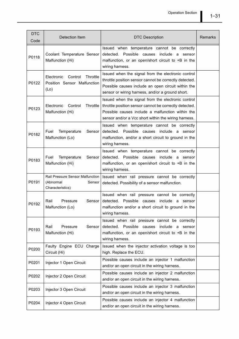
Operation Section1–31
P0118Coolant Temperature SensorMalfunction (Hi)
Issued when temperature cannot be correctlydetected. Possible causes include a sensormalfunction, or an open/short circuit to +B in thewiring harness.
P0122Electronic Control ThrottlePosition Sensor Malfunction(Lo)
Issued when the signal from the electronic controlthrottle position sensor cannot be correctly detected.Possible causes include an open circuit within thesensor or wiring harness, and/or a ground short.
P0123Electronic Control ThrottleMalfunction (Hi)
Issued when the signal from the electronic controlthrottle position sensor cannot be correctly detected.Possible causes include a malfunction within thesensor and/or a Vcc short within the wiring harness.
P0182Fuel Temperature SensorMalfunction (Lo)
Issued when temperature cannot be correctlydetected. Possible causes include a sensormalfunction, and/or a short circuit to ground in thewiring harness.
P0183Fuel Temperature SensorMalfunction (Hi)
Issued when temperature cannot be correctlydetected. Possible causes include a sensormalfunction, or an open/short circuit to +B in thewiring harness.
P0191Rail Pressure Sensor Malfunction(Abnormal SensorCharacteristics)
Issued when rail pressure cannot be correctlydetected. Possibility of a sensor malfunction.
P0192Rail Pressure SensorMalfunction (Lo)
Issued when rail pressure cannot be correctlydetected. Possible causes include a sensormalfunction and/or a short circuit to ground in thewiring harness.
P0193Rail Pressure SensorMalfunction (Hi)
Issued when rail pressure cannot be correctlydetected. Possible causes include a sensormalfunction, or an open/short circuit to +B in thewiring harness.
P0200Faulty Engine ECU ChargeCircuit (Hi)
Issued when the injector activation voltage is toohigh. Replace the ECU.
P0201 Injector 1 Open CircuitPossible causes include an injector 1 malfunctionand/or an open circuit in the wiring harness.
P0202 Injector 2 Open CircuitPossible causes include an injector 2 malfunctionand/or an open circuit in the wiring harness.
P0203 Injector 3 Open CircuitPossible causes include an injector 3 malfunctionand/or an open circuit in the wiring harness.
P0204 Injector 4 Open CircuitPossible causes include an injector 4 malfunctionand/or an open circuit in the wiring harness.
DTC
CodeDetection Item DTC Description Remarks
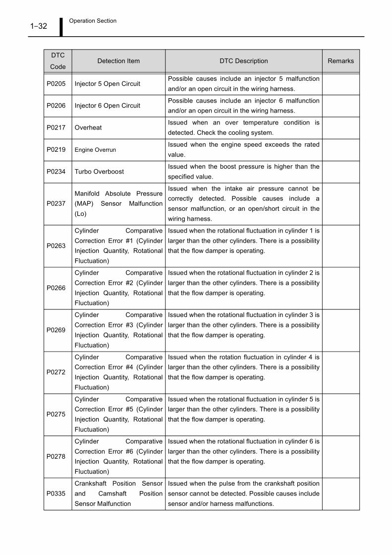
Operation Section1–32
P0205 Injector 5 Open CircuitPossible causes include an injector 5 malfunctionand/or an open circuit in the wiring harness.
P0206 Injector 6 Open CircuitPossible causes include an injector 6 malfunctionand/or an open circuit in the wiring harness.
P0217 OverheatIssued when an over temperature condition isdetected. Check the cooling system.
P0219 Engine OverrunIssued when the engine speed exceeds the ratedvalue.
P0234 Turbo OverboostIssued when the boost pressure is higher than thespecified value.
P0237Manifold Absolute Pressure(MAP) Sensor Malfunction(Lo)
Issued when the intake air pressure cannot becorrectly detected. Possible causes include asensor malfunction, or an open/short circuit in thewiring harness.
P0263
Cylinder ComparativeCorrection Error #1 (CylinderInjection Quantity, RotationalFluctuation)
Issued when the rotational fluctuation in cylinder 1 islarger than the other cylinders. There is a possibilitythat the flow damper is operating.
P0266
Cylinder ComparativeCorrection Error #2 (CylinderInjection Quantity, RotationalFluctuation)
Issued when the rotational fluctuation in cylinder 2 islarger than the other cylinders. There is a possibilitythat the flow damper is operating.
P0269
Cylinder ComparativeCorrection Error #3 (CylinderInjection Quantity, RotationalFluctuation)
Issued when the rotational fluctuation in cylinder 3 islarger than the other cylinders. There is a possibilitythat the flow damper is operating.
P0272
Cylinder ComparativeCorrection Error #4 (CylinderInjection Quantity, RotationalFluctuation)
Issued when the rotation fluctuation in cylinder 4 islarger than the other cylinders. There is a possibilitythat the flow damper is operating.
P0275
Cylinder ComparativeCorrection Error #5 (CylinderInjection Quantity, RotationalFluctuation)
Issued when the rotational fluctuation in cylinder 5 islarger than the other cylinders. There is a possibilitythat the flow damper is operating.
P0278
Cylinder ComparativeCorrection Error #6 (CylinderInjection Quantity, RotationalFluctuation)
Issued when the rotational fluctuation in cylinder 6 islarger than the other cylinders. There is a possibilitythat the flow damper is operating.
P0335Crankshaft Position Sensorand Camshaft PositionSensor Malfunction
Issued when the pulse from the crankshaft positionsensor cannot be detected. Possible causes includesensor and/or harness malfunctions.
DTC
CodeDetection Item DTC Description Remarks
Operation Section1–33
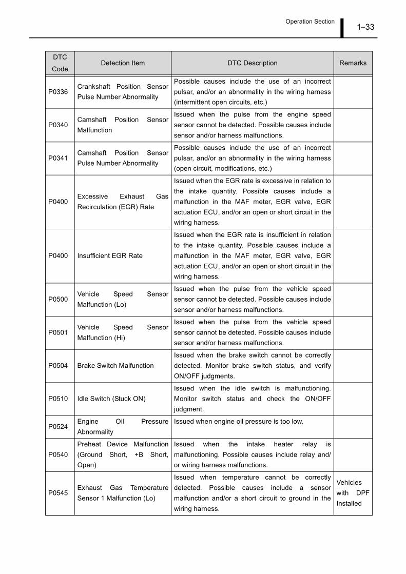
P0336Crankshaft Position SensorPulse Number Abnormality
Possible causes include the use of an incorrectpulsar, and/or an abnormality in the wiring harness(intermittent open circuits, etc.)
P0340Camshaft Position SensorMalfunction
Issued when the pulse from the engine speedsensor cannot be detected. Possible causes includesensor and/or harness malfunctions.
P0341Camshaft Position SensorPulse Number Abnormality
Possible causes include the use of an incorrectpulsar, and/or an abnormality in the wiring harness(open circuit, modifications, etc.)
P0400Excessive Exhaust GasRecirculation (EGR) Rate
Issued when the EGR rate is excessive in relation tothe intake quantity. Possible causes include amalfunction in the MAF meter, EGR valve, EGRactuation ECU, and/or an open or short circuit in thewiring harness.
P0400 Insufficient EGR Rate
Issued when the EGR rate is insufficient in relationto the intake quantity. Possible causes include amalfunction in the MAF meter, EGR valve, EGRactuation ECU, and/or an open or short circuit in thewiring harness.
P0500Vehicle Speed SensorMalfunction (Lo)
Issued when the pulse from the vehicle speedsensor cannot be detected. Possible causes includesensor and/or harness malfunctions.
P0501Vehicle Speed SensorMalfunction (Hi)
Issued when the pulse from the vehicle speedsensor cannot be detected. Possible causes includesensor and/or harness malfunctions.
P0504 Brake Switch MalfunctionIssued when the brake switch cannot be correctlydetected. Monitor brake switch status, and verifyON/OFF judgments.
P0510 Idle Switch (Stuck ON)Issued when the idle switch is malfunctioning.Monitor switch status and check the ON/OFFjudgment.
P0524Engine Oil PressureAbnormality
Issued when engine oil pressure is too low.
P0540Preheat Device Malfunction(Ground Short, +B Short,Open)
Issued when the intake heater relay ismalfunctioning. Possible causes include relay and/or wiring harness malfunctions.
P0545Exhaust Gas TemperatureSensor 1 Malfunction (Lo)
Issued when temperature cannot be correctlydetected. Possible causes include a sensormalfunction and/or a short circuit to ground in thewiring harness.
Vehicleswith DPFInstalled
DTC
CodeDetection Item DTC Description Remarks
Operation Section1–34
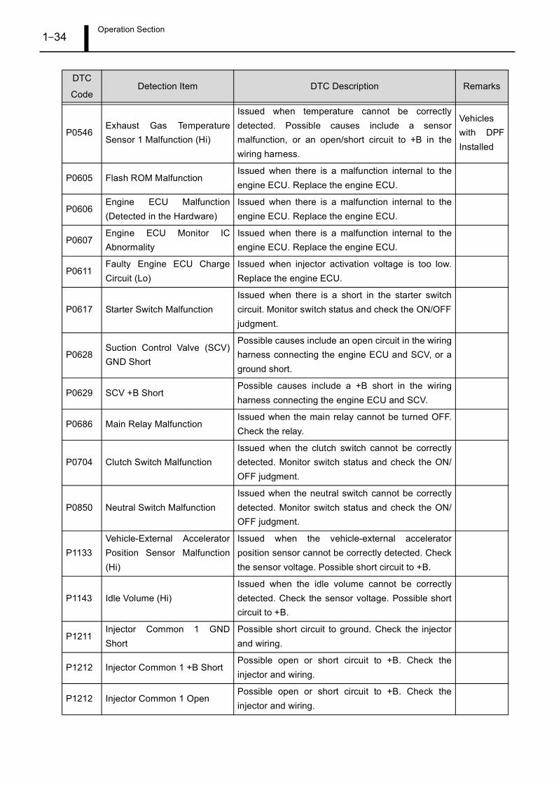
P0546Exhaust Gas TemperatureSensor 1 Malfunction (Hi)
Issued when temperature cannot be correctlydetected. Possible causes include a sensormalfunction, or an open/short circuit to +B in thewiring harness.
Vehicleswith DPFInstalled
P0605 Flash ROM MalfunctionIssued when there is a malfunction internal to theengine ECU. Replace the engine ECU.
P0606Engine ECU Malfunction(Detected in the Hardware)
Issued when there is a malfunction internal to theengine ECU. Replace the engine ECU.
P0607Engine ECU Monitor ICAbnormality
Issued when there is a malfunction internal to theengine ECU. Replace the engine ECU.
P0611Faulty Engine ECU ChargeCircuit (Lo)
Issued when injector activation voltage is too low.Replace the engine ECU.
P0617 Starter Switch MalfunctionIssued when there is a short in the starter switchcircuit. Monitor switch status and check the ON/OFFjudgment.
P0628Suction Control Valve (SCV)GND Short
Possible causes include an open circuit in the wiringharness connecting the engine ECU and SCV, or aground short.
P0629 SCV +B ShortPossible causes include a +B short in the wiringharness connecting the engine ECU and SCV.
P0686 Main Relay MalfunctionIssued when the main relay cannot be turned OFF.Check the relay.
P0704 Clutch Switch MalfunctionIssued when the clutch switch cannot be correctlydetected. Monitor switch status and check the ON/OFF judgment.
P0850 Neutral Switch MalfunctionIssued when the neutral switch cannot be correctlydetected. Monitor switch status and check the ON/OFF judgment.
P1133Vehicle-External AcceleratorPosition Sensor Malfunction(Hi)
Issued when the vehicle-external acceleratorposition sensor cannot be correctly detected. Checkthe sensor voltage. Possible short circuit to +B.
P1143 Idle Volume (Hi)Issued when the idle volume cannot be correctlydetected. Check the sensor voltage. Possible shortcircuit to +B.
P1211Injector Common 1 GNDShort
Possible short circuit to ground. Check the injectorand wiring.
P1212 Injector Common 1 +B ShortPossible open or short circuit to +B. Check theinjector and wiring.
P1212 Injector Common 1 OpenPossible open or short circuit to +B. Check theinjector and wiring.
DTC
CodeDetection Item DTC Description Remarks
Operation Section1–35
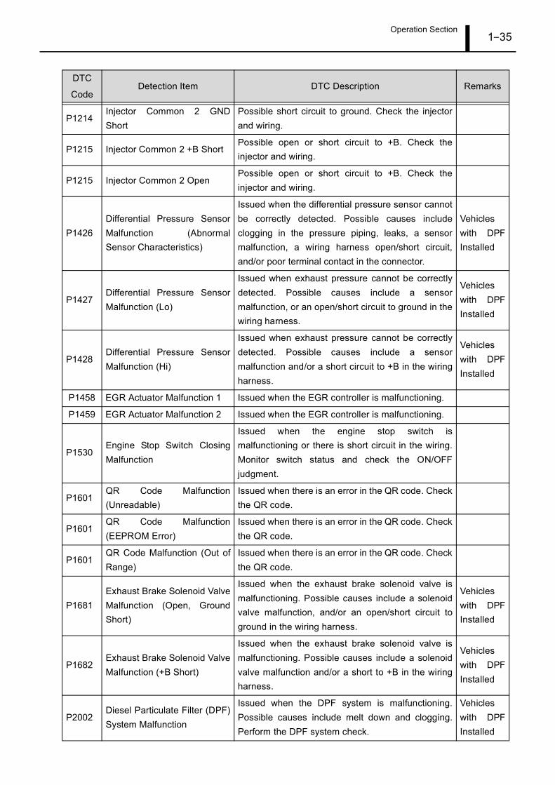
P1214Injector Common 2 GNDShort
Possible short circuit to ground. Check the injectorand wiring.
P1215 Injector Common 2 +B ShortPossible open or short circuit to +B. Check theinjector and wiring.
P1215 Injector Common 2 OpenPossible open or short circuit to +B. Check theinjector and wiring.
P1426Differential Pressure SensorMalfunction (AbnormalSensor Characteristics)
Issued when the differential pressure sensor cannotbe correctly detected. Possible causes includeclogging in the pressure piping, leaks, a sensormalfunction, a wiring harness open/short circuit,and/or poor terminal contact in the connector.
Vehicleswith DPFInstalled
P1427Differential Pressure SensorMalfunction (Lo)
Issued when exhaust pressure cannot be correctlydetected. Possible causes include a sensormalfunction, or an open/short circuit to ground in thewiring harness.
Vehicleswith DPFInstalled
P1428Differential Pressure SensorMalfunction (Hi)
Issued when exhaust pressure cannot be correctlydetected. Possible causes include a sensormalfunction and/or a short circuit to +B in the wiringharness.
Vehicleswith DPFInstalled
P1458 EGR Actuator Malfunction 1 Issued when the EGR controller is malfunctioning.
P1459 EGR Actuator Malfunction 2 Issued when the EGR controller is malfunctioning.
P1530Engine Stop Switch ClosingMalfunction
Issued when the engine stop switch ismalfunctioning or there is short circuit in the wiring.Monitor switch status and check the ON/OFFjudgment.
P1601QR Code Malfunction(Unreadable)
Issued when there is an error in the QR code. Checkthe QR code.
P1601QR Code Malfunction(EEPROM Error)
Issued when there is an error in the QR code. Checkthe QR code.
P1601QR Code Malfunction (Out ofRange)
Issued when there is an error in the QR code. Checkthe QR code.
P1681Exhaust Brake Solenoid ValveMalfunction (Open, GroundShort)
Issued when the exhaust brake solenoid valve ismalfunctioning. Possible causes include a solenoidvalve malfunction, and/or an open/short circuit toground in the wiring harness.
Vehicleswith DPFInstalled
P1682Exhaust Brake Solenoid ValveMalfunction (+B Short)
Issued when the exhaust brake solenoid valve ismalfunctioning. Possible causes include a solenoidvalve malfunction and/or a short to +B in the wiringharness.
Vehicleswith DPFInstalled
P2002Diesel Particulate Filter (DPF)System Malfunction
Issued when the DPF system is malfunctioning.Possible causes include melt down and clogging.Perform the DPF system check.
Vehicleswith DPFInstalled
DTC
CodeDetection Item DTC Description Remarks
Operation Section1–36
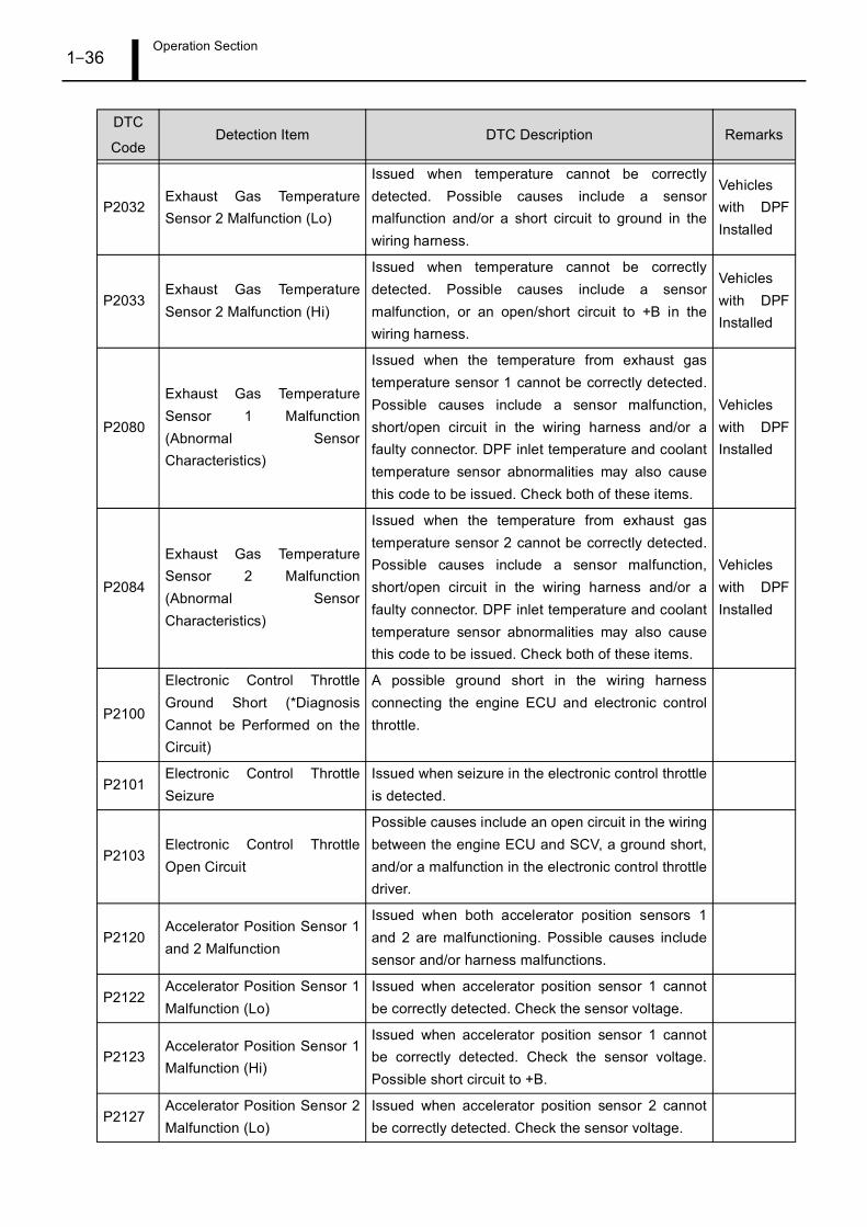
P2032Exhaust Gas TemperatureSensor 2 Malfunction (Lo)
Issued when temperature cannot be correctlydetected. Possible causes include a sensormalfunction and/or a short circuit to ground in thewiring harness.
Vehicleswith DPFInstalled
P2033Exhaust Gas TemperatureSensor 2 Malfunction (Hi)
Issued when temperature cannot be correctlydetected. Possible causes include a sensormalfunction, or an open/short circuit to +B in thewiring harness.
Vehicleswith DPFInstalled
P2080
Exhaust Gas TemperatureSensor 1 Malfunction(Abnormal SensorCharacteristics)
Issued when the temperature from exhaust gastemperature sensor 1 cannot be correctly detected.Possible causes include a sensor malfunction,short/open circuit in the wiring harness and/or afaulty connector. DPF inlet temperature and coolanttemperature sensor abnormalities may also causethis code to be issued. Check both of these items.
Vehicleswith DPFInstalled
P2084
Exhaust Gas TemperatureSensor 2 Malfunction(Abnormal SensorCharacteristics)
Issued when the temperature from exhaust gastemperature sensor 2 cannot be correctly detected.Possible causes include a sensor malfunction,short/open circuit in the wiring harness and/or afaulty connector. DPF inlet temperature and coolanttemperature sensor abnormalities may also causethis code to be issued. Check both of these items.
Vehicleswith DPFInstalled
P2100
Electronic Control ThrottleGround Short (*DiagnosisCannot be Performed on theCircuit)
A possible ground short in the wiring harnessconnecting the engine ECU and electronic controlthrottle.
P2101Electronic Control ThrottleSeizure
Issued when seizure in the electronic control throttleis detected.
P2103Electronic Control ThrottleOpen Circuit
Possible causes include an open circuit in the wiringbetween the engine ECU and SCV, a ground short,and/or a malfunction in the electronic control throttledriver.
P2120Accelerator Position Sensor 1and 2 Malfunction
Issued when both accelerator position sensors 1and 2 are malfunctioning. Possible causes includesensor and/or harness malfunctions.
P2122Accelerator Position Sensor 1Malfunction (Lo)
Issued when accelerator position sensor 1 cannotbe correctly detected. Check the sensor voltage.
P2123Accelerator Position Sensor 1Malfunction (Hi)
Issued when accelerator position sensor 1 cannotbe correctly detected. Check the sensor voltage.Possible short circuit to +B.
P2127Accelerator Position Sensor 2Malfunction (Lo)
Issued when accelerator position sensor 2 cannotbe correctly detected. Check the sensor voltage.
DTC
CodeDetection Item DTC Description Remarks
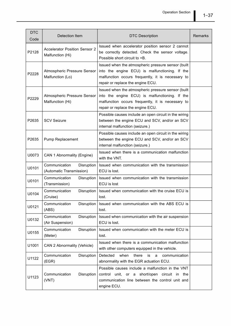
Operation Section1–37
P2128Accelerator Position Sensor 2Malfunction (Hi)
Issued when accelerator position sensor 2 cannotbe correctly detected. Check the sensor voltage.Possible short circuit to +B.
P2228Atmospheric Pressure SensorMalfunction (Lo)
Issued when the atmospheric pressure sensor (builtinto the engine ECU) is malfunctioning. If themalfunction occurs frequently, it is necessary torepair or replace the engine ECU.
P2229Atmospheric Pressure SensorMalfunction (Hi)
Issued when the atmospheric pressure sensor (builtinto the engine ECU) is malfunctioning. If themalfunction occurs frequently, it is necessary torepair or replace the engine ECU.
P2635 SCV SeizurePossible causes include an open circuit in the wiringbetween the engine ECU and SCV, and/or an SCVinternal malfunction (seizure.)
P2635 Pump ReplacementPossible causes include an open circuit in the wiringbetween the engine ECU and SCV, and/or an SCVinternal malfunction (seizure.)
U0073 CAN 1 Abnormality (Engine)Issued when there is a communication malfunctionwith the VNT.
U0101Communication Disruption(Automatic Transmission)
Issued when communication with the transmissionECU is lost.
U0101Communication Disruption(Transmission)
Issued when communication with the transmissionECU is lost
U0104Communication Disruption(Cruise)
Issued when communication with the cruise ECU islost.
U0121Communication Disruption(ABS)
Issued when communication with the ABS ECU islost.
U0132Communication Disruption(Air Suspension)
Issued when communication with the air suspensionECU is lost.
U0155Communication Disruption(Meter)
Issued when communication with the meter ECU islost.
U1001 CAN 2 Abnormality (Vehicle)Issued when there is a communication malfunctionwith other computers equipped in the vehicle.
U1122Communication Disruption(EGR)
Detected when there is a communicationabnormality with the EGR actuation ECU.
U1123Communication Disruption(VNT)
Possible causes include a malfunction in the VNTcontrol unit, or a short/open circuit in thecommunication line between the control unit andengine ECU.
DTC
CodeDetection Item DTC Description Remarks
Operation Section1–38
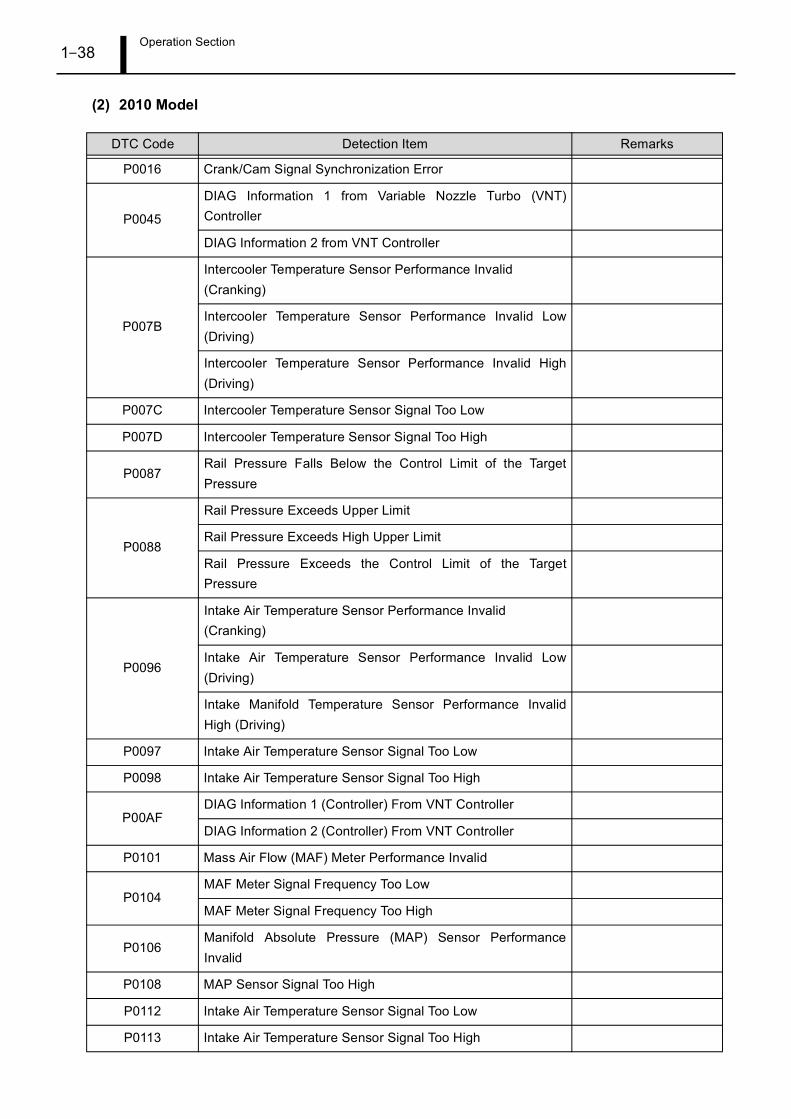
(2) 2010 Model
DTC Code Detection Item Remarks
P0016 Crank/Cam Signal Synchronization Error
P0045
DIAG Information 1 from Variable Nozzle Turbo (VNT)Controller
DIAG Information 2 from VNT Controller
P007B
Intercooler Temperature Sensor Performance Invalid (Cranking)
Intercooler Temperature Sensor Performance Invalid Low(Driving)
Intercooler Temperature Sensor Performance Invalid High(Driving)
P007C Intercooler Temperature Sensor Signal Too Low
P007D Intercooler Temperature Sensor Signal Too High
P0087Rail Pressure Falls Below the Control Limit of the TargetPressure
P0088
Rail Pressure Exceeds Upper Limit
Rail Pressure Exceeds High Upper Limit
Rail Pressure Exceeds the Control Limit of the TargetPressure
P0096
Intake Air Temperature Sensor Performance Invalid (Cranking)
Intake Air Temperature Sensor Performance Invalid Low(Driving)
Intake Manifold Temperature Sensor Performance InvalidHigh (Driving)
P0097 Intake Air Temperature Sensor Signal Too Low
P0098 Intake Air Temperature Sensor Signal Too High
P00AFDIAG Information 1 (Controller) From VNT Controller
DIAG Information 2 (Controller) From VNT Controller
P0101 Mass Air Flow (MAF) Meter Performance Invalid
P0104MAF Meter Signal Frequency Too Low
MAF Meter Signal Frequency Too High
P0106Manifold Absolute Pressure (MAP) Sensor PerformanceInvalid
P0108 MAP Sensor Signal Too High
P0112 Intake Air Temperature Sensor Signal Too Low
P0113 Intake Air Temperature Sensor Signal Too High
Operation Section1–39
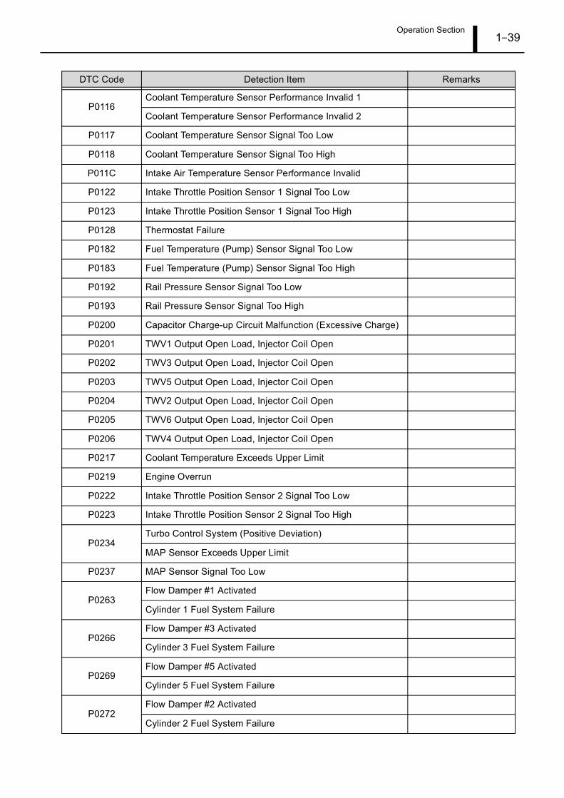
P0116Coolant Temperature Sensor Performance Invalid 1
Coolant Temperature Sensor Performance Invalid 2
P0117 Coolant Temperature Sensor Signal Too Low
P0118 Coolant Temperature Sensor Signal Too High
P011C Intake Air Temperature Sensor Performance Invalid
P0122 Intake Throttle Position Sensor 1 Signal Too Low
P0123 Intake Throttle Position Sensor 1 Signal Too High
P0128 Thermostat Failure
P0182 Fuel Temperature (Pump) Sensor Signal Too Low
P0183 Fuel Temperature (Pump) Sensor Signal Too High
P0192 Rail Pressure Sensor Signal Too Low
P0193 Rail Pressure Sensor Signal Too High
P0200 Capacitor Charge-up Circuit Malfunction (Excessive Charge)
P0201 TWV1 Output Open Load, Injector Coil Open
P0202 TWV3 Output Open Load, Injector Coil Open
P0203 TWV5 Output Open Load, Injector Coil Open
P0204 TWV2 Output Open Load, Injector Coil Open
P0205 TWV6 Output Open Load, Injector Coil Open
P0206 TWV4 Output Open Load, Injector Coil Open
P0217 Coolant Temperature Exceeds Upper Limit
P0219 Engine Overrun
P0222 Intake Throttle Position Sensor 2 Signal Too Low
P0223 Intake Throttle Position Sensor 2 Signal Too High
P0234Turbo Control System (Positive Deviation)
MAP Sensor Exceeds Upper Limit
P0237 MAP Sensor Signal Too Low
P0263Flow Damper #1 Activated
Cylinder 1 Fuel System Failure
P0266Flow Damper #3 Activated
Cylinder 3 Fuel System Failure
P0269Flow Damper #5 Activated
Cylinder 5 Fuel System Failure
P0272Flow Damper #2 Activated
Cylinder 2 Fuel System Failure
DTC Code Detection Item Remarks
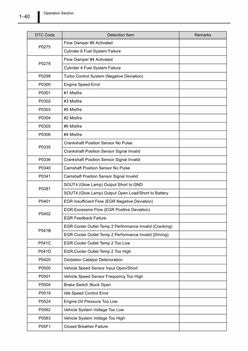
Operation Section1–40
P0275Flow Damper #6 Activated
Cylinder 6 Fuel System Failure
P0278Flow Damper #4 Activated
Cylinder 4 Fuel System Failure
P0299 Turbo Control System (Negative Deviation)
P0300 Engine Speed Error
P0301 #1 Misfire
P0302 #3 Misfire
P0303 #5 Misfire
P0304 #2 Misfire
P0305 #6 Misfire
P0306 #4 Misfire
P0335Crankshaft Position Sensor No Pulse
Crankshaft Position Sensor Signal Invalid
P0336 Crankshaft Position Sensor Signal Invalid
P0340 Camshaft Position Sensor No Pulse
P0341 Camshaft Position Sensor Signal Invalid
P0381SOUT4 (Glow Lamp) Output Short to GND
SOUT4 (Glow Lamp) Output Open Load/Short to Battery
P0401 EGR Insufficient Flow (EGR Negative Deviation)
P0402EGR Excessive Flow (EGR Positive Deviation)
EGR Feedback Failure
P041BEGR Cooler Outlet Temp 2 Performance Invalid (Cranking)
EGR Cooler Outlet Temp 2 Performance Invalid (Driving)
P041C EGR Cooler Outlet Temp 2 Too Low
P041D EGR Cooler Outlet Temp 2 Too High
P0420 Oxidation Catalyst Deterioration
P0500 Vehicle Speed Sensor Input Open/Short
P0501 Vehicle Speed Sensor Frequency Too High
P0504 Brake Switch Stuck Open
P0519 Idle Speed Control Error
P0524 Engine Oil Pressure Too Low
P0562 Vehicle System Voltage Too Low
P0563 Vehicle System Voltage Too High
P05F1 Closed Breather Failure
DTC Code Detection Item Remarks
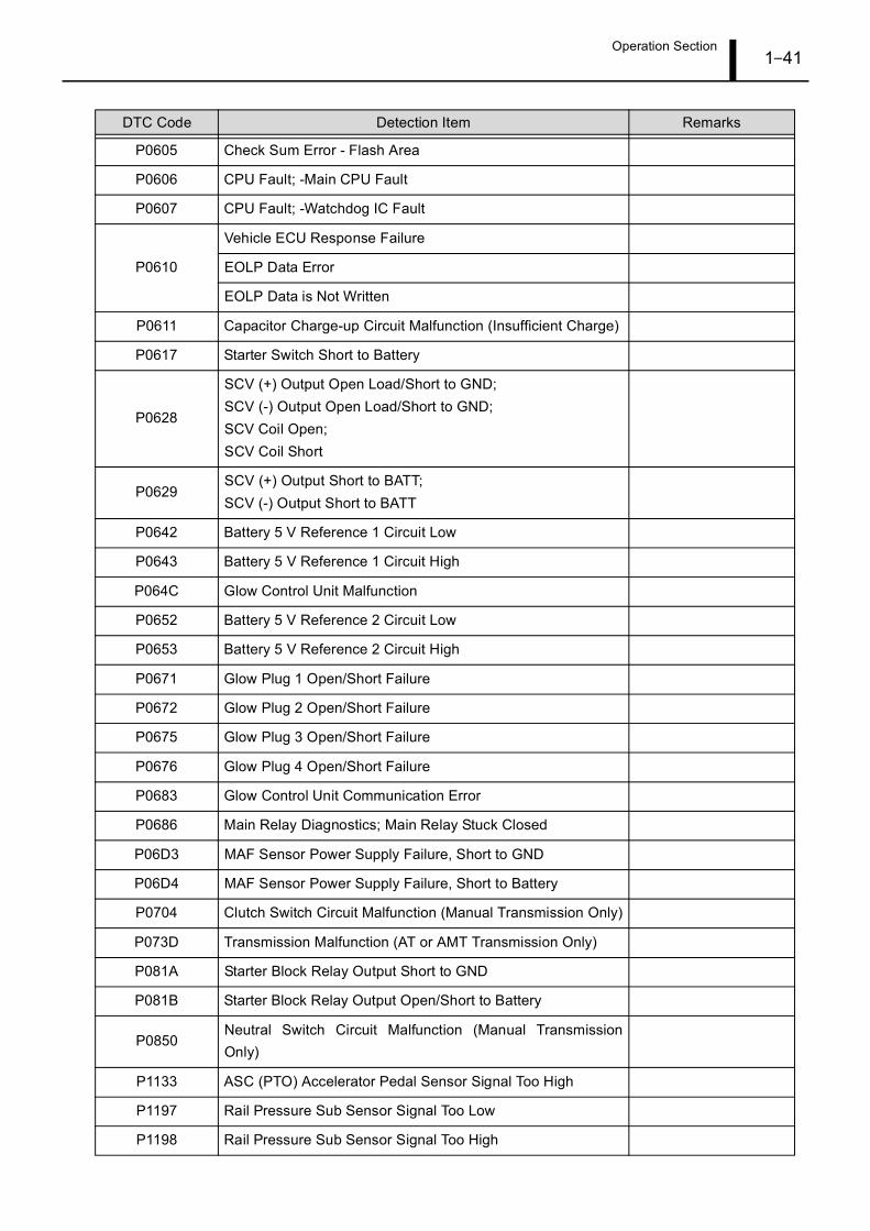
Operation Section1–41
P0605 Check Sum Error - Flash Area
P0606 CPU Fault; -Main CPU Fault
P0607 CPU Fault; -Watchdog IC Fault
P0610
Vehicle ECU Response Failure
EOLP Data Error
EOLP Data is Not Written
P0611 Capacitor Charge-up Circuit Malfunction (Insufficient Charge)
P0617 Starter Switch Short to Battery
P0628
SCV (+) Output Open Load/Short to GND;SCV (-) Output Open Load/Short to GND;SCV Coil Open;SCV Coil Short
P0629SCV (+) Output Short to BATT; SCV (-) Output Short to BATT
P0642 Battery 5 V Reference 1 Circuit Low
P0643 Battery 5 V Reference 1 Circuit High
P064C Glow Control Unit Malfunction
P0652 Battery 5 V Reference 2 Circuit Low
P0653 Battery 5 V Reference 2 Circuit High
P0671 Glow Plug 1 Open/Short Failure
P0672 Glow Plug 2 Open/Short Failure
P0675 Glow Plug 3 Open/Short Failure
P0676 Glow Plug 4 Open/Short Failure
P0683 Glow Control Unit Communication Error
P0686 Main Relay Diagnostics; Main Relay Stuck Closed
P06D3 MAF Sensor Power Supply Failure, Short to GND
P06D4 MAF Sensor Power Supply Failure, Short to Battery
P0704 Clutch Switch Circuit Malfunction (Manual Transmission Only)
P073D Transmission Malfunction (AT or AMT Transmission Only)
P081A Starter Block Relay Output Short to GND
P081B Starter Block Relay Output Open/Short to Battery
P0850Neutral Switch Circuit Malfunction (Manual TransmissionOnly)
P1133 ASC (PTO) Accelerator Pedal Sensor Signal Too High
P1197 Rail Pressure Sub Sensor Signal Too Low
P1198 Rail Pressure Sub Sensor Signal Too High
DTC Code Detection Item Remarks
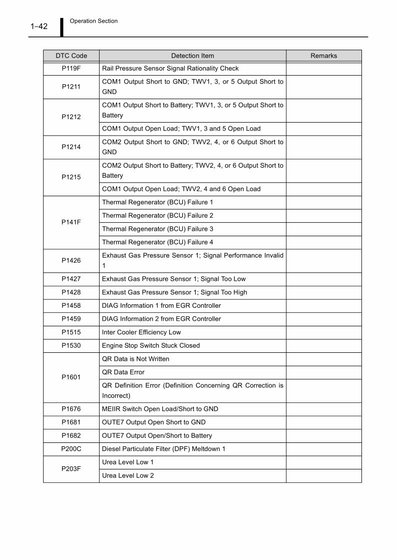
Operation Section1–42
P119F Rail Pressure Sensor Signal Rationality Check
P1211COM1 Output Short to GND; TWV1, 3, or 5 Output Short toGND
P1212
COM1 Output Short to Battery; TWV1, 3, or 5 Output Short toBattery
COM1 Output Open Load; TWV1, 3 and 5 Open Load
P1214COM2 Output Short to GND; TWV2, 4, or 6 Output Short toGND
P1215
COM2 Output Short to Battery; TWV2, 4, or 6 Output Short toBattery
COM1 Output Open Load; TWV2, 4 and 6 Open Load
P141F
Thermal Regenerator (BCU) Failure 1
Thermal Regenerator (BCU) Failure 2
Thermal Regenerator (BCU) Failure 3
Thermal Regenerator (BCU) Failure 4
P1426Exhaust Gas Pressure Sensor 1; Signal Performance Invalid1
P1427 Exhaust Gas Pressure Sensor 1; Signal Too Low
P1428 Exhaust Gas Pressure Sensor 1; Signal Too High
P1458 DIAG Information 1 from EGR Controller
P1459 DIAG Information 2 from EGR Controller
P1515 Inter Cooler Efficiency Low
P1530 Engine Stop Switch Stuck Closed
P1601
QR Data is Not Written
QR Data Error
QR Definition Error (Definition Concerning QR Correction isIncorrect)
P1676 MEIIR Switch Open Load/Short to GND
P1681 OUTE7 Output Open Short to GND
P1682 OUTE7 Output Open/Short to Battery
P200C Diesel Particulate Filter (DPF) Meltdown 1
P203FUrea Level Low 1
Urea Level Low 2
DTC Code Detection Item Remarks
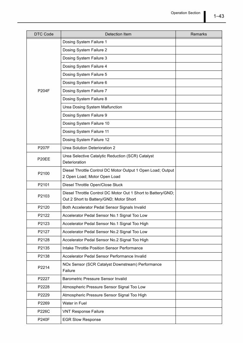
Operation Section1–43
P204F
Dosing System Failure 1
Dosing System Failure 2
Dosing System Failure 3
Dosing System Failure 4
Dosing System Failure 5
Dosing System Failure 6
Dosing System Failure 7
Dosing System Failure 8
Urea Dosing System Malfunction
Dosing System Failure 9
Dosing System Failure 10
Dosing System Failure 11
Dosing System Failure 12
P207F Urea Solution Deterioration 2
P20EEUrea Selective Catalytic Reduction (SCR) CatalystDeterioration
P2100Diesel Throttle Control DC Motor Output 1 Open Load; Output2 Open Load; Motor Open Load
P2101 Diesel Throttle Open/Close Stuck
P2103Diesel Throttle Control DC Motor Out 1 Short to Battery/GND;Out 2 Short to Battery/GND; Motor Short
P2120 Both Accelerator Pedal Sensor Signals Invalid
P2122 Accelerator Pedal Sensor No.1 Signal Too Low
P2123 Accelerator Pedal Sensor No.1 Signal Too High
P2127 Accelerator Pedal Sensor No.2 Signal Too Low
P2128 Accelerator Pedal Sensor No.2 Signal Too High
P2135 Intake Throttle Position Sensor Performance
P2138 Accelerator Pedal Sensor Performance Invalid
P2214NOx Sensor (SCR Catalyst Downstream) PerformanceFailure
P2227 Barometric Pressure Sensor Invalid
P2228 Atmospheric Pressure Sensor Signal Too Low
P2229 Atmospheric Pressure Sensor Signal Too High
P2269 Water in Fuel
P226C VNT Response Failure
P240F EGR Slow Response
DTC Code Detection Item Remarks
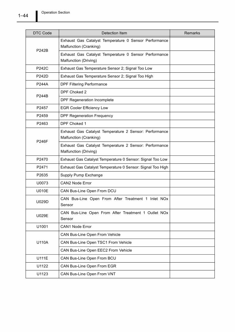
Operation Section1–44
P242B
Exhaust Gas Catalyst Temperature 0 Sensor PerformanceMalfunction (Cranking)
Exhaust Gas Catalyst Temperature 0 Sensor PerformanceMalfunction (Driving)
P242C Exhaust Gas Temperature Sensor 2; Signal Too Low
P242D Exhaust Gas Temperature Sensor 2; Signal Too High
P244A DPF Filtering Performance
P244BDPF Choked 2
DPF Regeneration Incomplete
P2457 EGR Cooler Efficiency Low
P2459 DPF Regeneration Frequency
P2463 DPF Choked 1
P246F
Exhaust Gas Catalyst Temperature 2 Sensor: PerformanceMalfunction (Cranking)
Exhaust Gas Catalyst Temperature 2 Sensor: PerformanceMalfunction (Driving)
P2470 Exhaust Gas Catalyst Temperature 0 Sensor: Signal Too Low
P2471 Exhaust Gas Catalyst Temperature 0 Sensor: Signal Too High
P2635 Supply Pump Exchange
U0073 CAN2 Node Error
U010E CAN Bus-Line Open From DCU
U029DCAN Bus-Line Open From After Treatment 1 Inlet NOxSensor
U029ECAN Bus-Line Open From After Treatment 1 Outlet NOxSensor
U1001 CAN1 Node Error
U110A
CAN Bus-Line Open From Vehicle
CAN Bus-Line Open TSC1 From Vehicle
CAN Bus-Line Open EEC2 From Vehicle
U111E CAN Bus-Line Open From BCU
U1122 CAN Bus-Line Open From EGR
U1123 CAN Bus-Line Open From VNT
DTC Code Detection Item Remarks
Operation Section1–45
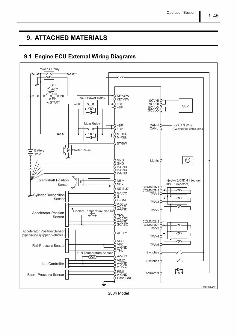
9. ATTACHED MATERIALS
9.1 Engine ECU External Wiring Diagrams
2004 Model
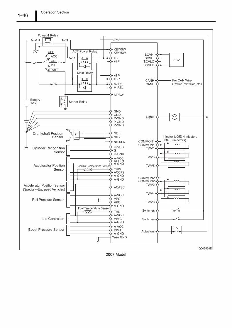
Operation Section1–46
2007 Model
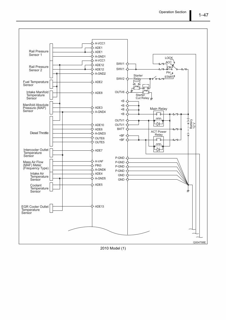
Operation Section1–47
2010 Model (1)
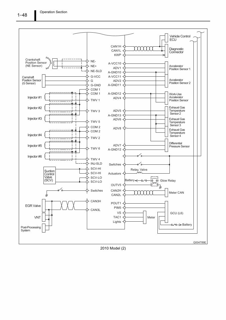
Operation Section1–48
2010 Model (2)

Operation Section1–49
9.2 Connector Terminal Layout
(1) 2004, 2007 model
Connector terminal layout
No. Code Terminal Description Remarks
1 (GND) Engine ECU ground (spare)
2 (GND) Engine ECU ground (spare)
3 IN3 -
4 IN3- -
5 +B Power
6 +B Power
7 +B Power
8 TAC1 -
9 TAC2 Tachometer signal (SINK)
10 POUT1 Rotary solenoid actuation signal 2007 model only
11 POUT2 -
12 POUT3 -
13 POUT4 -
14 PIN1 -
15 PIN2 -
16 - -
17 (BATT)
18 (CASE GND) Case ground (spare)
19 KWP2000 ISO9141-K
20 IN1 -
21 AD1 Accelerator position sensor 1
22 AD2 Accelerator position sensor 2
23 AD10 Vehicle-external accelerator position sensor
24 AD12 Differential pressure sensor 2007 model only
25 AD19 Exhaust gas temperature sensor 1 2007 model only
26 AD20 Exhaust gas temperature sensor 2 2007 model only
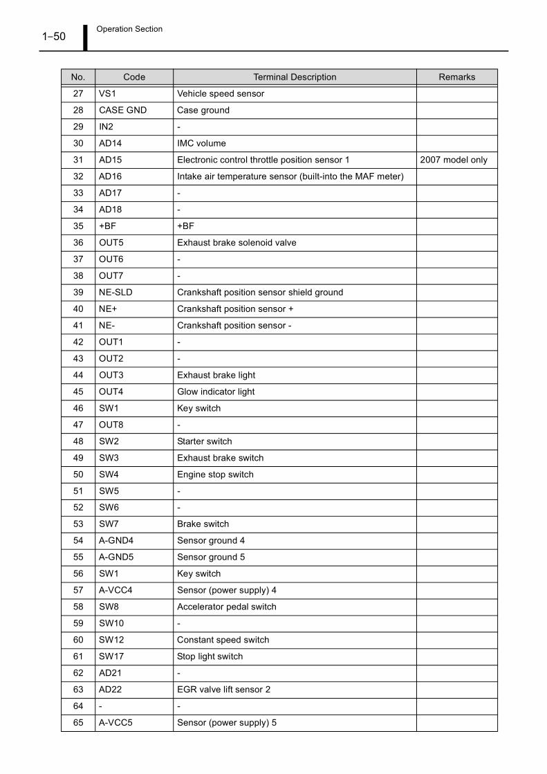
Operation Section1–50
27 VS1 Vehicle speed sensor
28 CASE GND Case ground
29 IN2 -
30 AD14 IMC volume
31 AD15 Electronic control throttle position sensor 1 2007 model only
32 AD16 Intake air temperature sensor (built-into the MAF meter)
33 AD17 -
34 AD18 -
35 +BF +BF
36 OUT5 Exhaust brake solenoid valve
37 OUT6 -
38 OUT7 -
39 NE-SLD Crankshaft position sensor shield ground
40 NE+ Crankshaft position sensor +
41 NE- Crankshaft position sensor -
42 OUT1 -
43 OUT2 -
44 OUT3 Exhaust brake light
45 OUT4 Glow indicator light
46 SW1 Key switch
47 OUT8 -
48 SW2 Starter switch
49 SW3 Exhaust brake switch
50 SW4 Engine stop switch
51 SW5 -
52 SW6 -
53 SW7 Brake switch
54 A-GND4 Sensor ground 4
55 A-GND5 Sensor ground 5
56 SW1 Key switch
57 A-VCC4 Sensor (power supply) 4
58 SW8 Accelerator pedal switch
59 SW10 -
60 SW12 Constant speed switch
61 SW17 Stop light switch
62 AD21 -
63 AD22 EGR valve lift sensor 2
64 - -
65 A-VCC5 Sensor (power supply) 5
No. Code Terminal Description Remarks
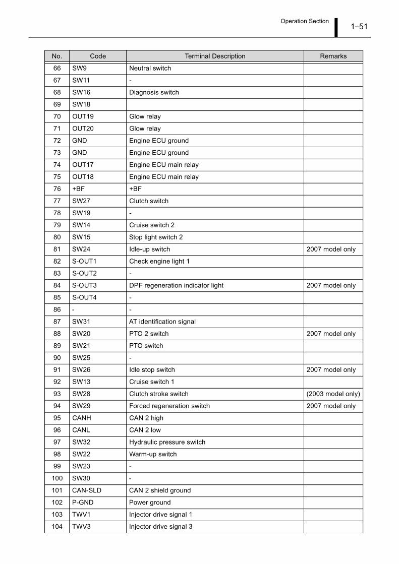
Operation Section1–51
66 SW9 Neutral switch
67 SW11 -
68 SW16 Diagnosis switch
69 SW18
70 OUT19 Glow relay
71 OUT20 Glow relay
72 GND Engine ECU ground
73 GND Engine ECU ground
74 OUT17 Engine ECU main relay
75 OUT18 Engine ECU main relay
76 +BF +BF
77 SW27 Clutch switch
78 SW19 -
79 SW14 Cruise switch 2
80 SW15 Stop light switch 2
81 SW24 Idle-up switch 2007 model only
82 S-OUT1 Check engine light 1
83 S-OUT2 -
84 S-OUT3 DPF regeneration indicator light 2007 model only
85 S-OUT4 -
86 - -
87 SW31 AT identification signal
88 SW20 PTO 2 switch 2007 model only
89 SW21 PTO switch
90 SW25 -
91 SW26 Idle stop switch 2007 model only
92 SW13 Cruise switch 1
93 SW28 Clutch stroke switch (2003 model only)
94 SW29 Forced regeneration switch 2007 model only
95 CANH CAN 2 high
96 CANL CAN 2 low
97 SW32 Hydraulic pressure switch
98 SW22 Warm-up switch
99 SW23 -
100 SW30 -
101 CAN-SLD CAN 2 shield ground
102 P-GND Power ground
103 TWV1 Injector drive signal 1
104 TWV3 Injector drive signal 3
No. Code Terminal Description Remarks
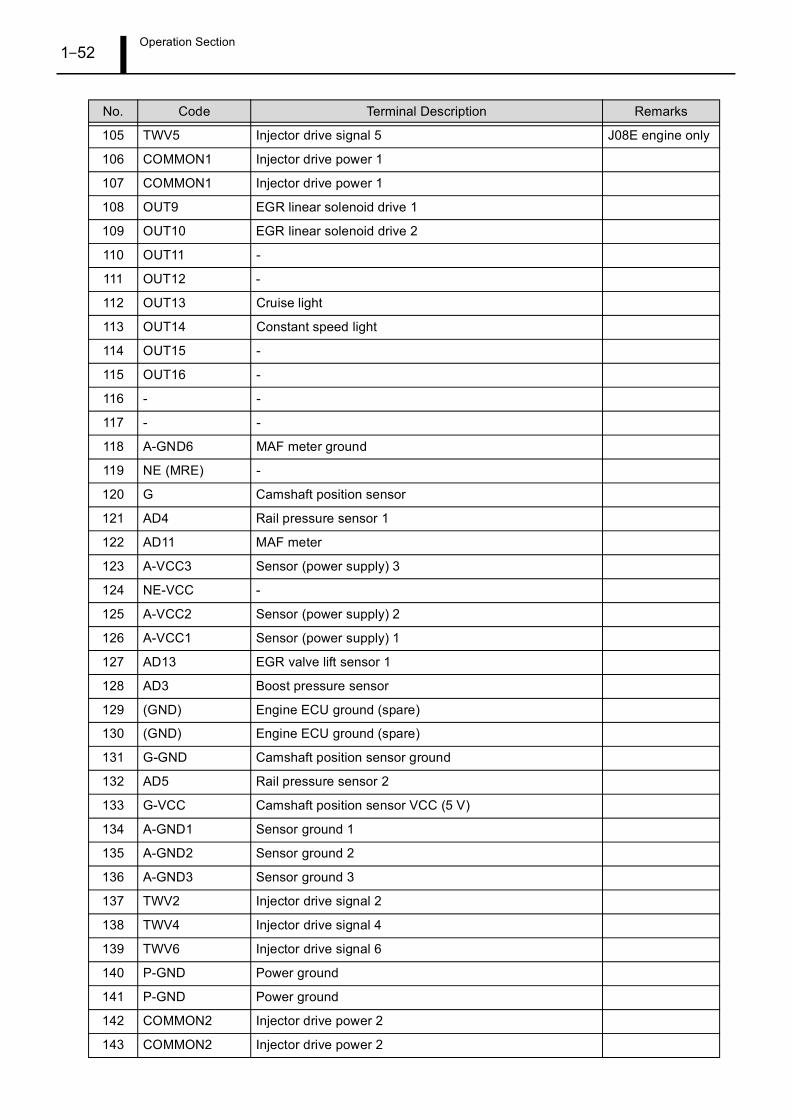
Operation Section1–52
105 TWV5 Injector drive signal 5 J08E engine only
106 COMMON1 Injector drive power 1
107 COMMON1 Injector drive power 1
108 OUT9 EGR linear solenoid drive 1
109 OUT10 EGR linear solenoid drive 2
110 OUT11 -
111 OUT12 -
112 OUT13 Cruise light
113 OUT14 Constant speed light
114 OUT15 -
115 OUT16 -
116 - -
117 - -
118 A-GND6 MAF meter ground
119 NE (MRE) -
120 G Camshaft position sensor
121 AD4 Rail pressure sensor 1
122 AD11 MAF meter
123 A-VCC3 Sensor (power supply) 3
124 NE-VCC -
125 A-VCC2 Sensor (power supply) 2
126 A-VCC1 Sensor (power supply) 1
127 AD13 EGR valve lift sensor 1
128 AD3 Boost pressure sensor
129 (GND) Engine ECU ground (spare)
130 (GND) Engine ECU ground (spare)
131 G-GND Camshaft position sensor ground
132 AD5 Rail pressure sensor 2
133 G-VCC Camshaft position sensor VCC (5 V)
134 A-GND1 Sensor ground 1
135 A-GND2 Sensor ground 2
136 A-GND3 Sensor ground 3
137 TWV2 Injector drive signal 2
138 TWV4 Injector drive signal 4
139 TWV6 Injector drive signal 6
140 P-GND Power ground
141 P-GND Power ground
142 COMMON2 Injector drive power 2
143 COMMON2 Injector drive power 2
No. Code Terminal Description Remarks
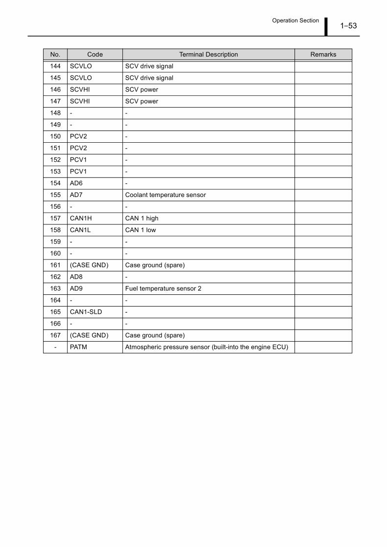
Operation Section1–53
144 SCVLO SCV drive signal
145 SCVLO SCV drive signal
146 SCVHI SCV power
147 SCVHI SCV power
148 - -
149 - -
150 PCV2 -
151 PCV2 -
152 PCV1 -
153 PCV1 -
154 AD6 -
155 AD7 Coolant temperature sensor
156 - -
157 CAN1H CAN 1 high
158 CAN1L CAN 1 low
159 - -
160 - -
161 (CASE GND) Case ground (spare)
162 AD8 -
163 AD9 Fuel temperature sensor 2
164 - -
165 CAN1-SLD -
166 - -
167 (CASE GND) Case ground (spare)
- PATM Atmospheric pressure sensor (built-into the engine ECU)
No. Code Terminal Description Remarks
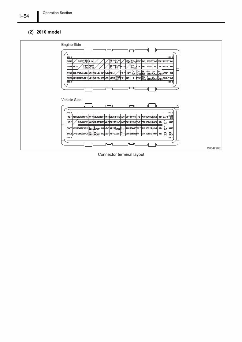
Operation Section1–54
(2) 2010 model
Connector terminal layout

Service Department DENSO CORPORATION1-1, Showa-cho, Kariya-shi, Aichi-ken, 448-8661, Japan


![INDEX [ ] · PDF filemodel/application sakura no hino j08e-t, 2010 (trucks) blue ribbon oil filter combination ..... c-1316 j08e-t, 2012 (trucks) blue ribbon](https://img.pdfslide.us/doc/110x75/5aac6f487f8b9a2e088cf780/index-sakura-no-hino-j08e-t-2010-trucks-blue-ribbon-oil-filter-combination.jpg)