Embed Size (px)
Citation preview

1 | P a g e 7 / 1 / 2 0 2 1
J. MICHAEL RUANE JUDICIAL CENTER HVAC SYSTEM EVALUATION SUMMARY
Visited September 16, 2020. Inspected the air handling units and toured the occupied portions of the building to determine if the spaces generally matched usage noted on the architectural plans. The J. Michael Ruane Judicial Center is a six-story building (including the basement), constructed in 2011, with a floor area of approximately 268,000 gross
square feet. The HVAC system includes 11 variable air volume (VAV) air handling units. The air handling units are generally in good condition. Filters and coils were generally clean. The dampers and actuators that were observed appeared to be in good condition. 1.0 Airflow Rate Per Person (Reduced Occupancy)
Total People
Total Air Outdoor Air
Courtroom
Supply Airflow (CFM)
Airflow Rate (CFM/Person)
Outside Airflow (CFM)
Airflow Rate (CFM/Person)
Jury Pool Room 40 3,120 78 1,560 39
Courtroom A 28 4,000 146 1,200 42
Courtroom B 14 1,400 100 370 26
Courtroom C 28 3,350 120 870 31
Courtroom D 32 3,400 106 1,080 34
Courtroom E 23 3,100 135 980 43
Courtroom F 23 2,900 126 920 40
Courtroom G 30 3,400 113 1,000 34
Courtroom H 30 3,200 107 1,010 34
Courtroom I 30 2,700 90 860 29
Courtroom J 30 3,100 104 990 33
Courtroom K 38 4,200 109 1,200 32
2.0 Recommendations Section Recommendation/Finding Action
2.1 Filtration Efficiency
No actionable items identified MERV-13/14 in use
2.2 Testing and Balancing
RTB-1 RTB-1: Test and rebalance air handling unit minimum outside air flow rate Complete
RTB-3 RTB-3: Increase outside air flow rate beyond minimum under non-peak conditions
Complete
RTB-5 RTB-5: Consider rebalancing all air inlets and outlets N/A RTB-6 RTB-6: Test and balance all air handler chilled and hot water coils In-progress

2 | P a g e 7 / 1 / 2 0 2 1
2.3 Equipment Maintenance and Upgrades
RE-1 Test existing air handling system dampers and actuators for proper operation
Complete
RE-4 Inspect VAV boxes and controllers Complete
RE-4 Test and balance VAV box flow rates N/A
2.4 Control System
RC-1 Implement a pre and post-occupancy flush sequence Complete
RC-3 Install controls required to introduce outside air beyond the minimum requirement
Complete
RC-5 Disable demand control ventilation sequences Complete
2.5 Additional Filtration and Air Cleaning
RFC-1 Install portable HEPA filters in high traffic areas – if courthouse is to operate at a high occupancy (i.e. 50-75% or greater), install portable HEPA filters in high traffic areas.
In progress
2.6 Humidity Control
No actionable items list – continuous monitoring for seasonal changes On-going
2.7 Other Recommendations
2.7.1 Route exhaust ductwork from 2nd floor mechanical room directly to the outdoors
Complete
2.7.2 Increase VAV minimum airflow from 40%to 50% in courtrooms Complete
2.7.3 Replace CO2 sensors that are malfunctioning or beyond their expected life of 5-10 years
In-progress

J. Michael Ruane Judicial Center Salem, MA
HVAC SYSTEM
EVALUATIONS
COVID-19
Office of Court Management
December 9, 2020

Tighe&Bond
J. Michael Ruane Judicial Center HVAC System Evaluation - COVID 19 1-1
Section 1
Existing Conditions and Site Observations
Tighe & Bond visited the J. Michael Ruane Judicial Center in Salem, MA on September 16,
2020. While on site, we inspected the air handling units and toured the occupied portions
of the building to determine if the spaces generally matched usage noted on the
architectural plans.
Site Visit Attendees:
• Office of Court Management:
o Marcos (Marc) Olivera, Facilities Supervisor
o Jim Cawley, Facilities, HVAC Specialist
• Tighe & Bond:
o Sean Pringle, PE, Project Mechanical Engineer
o Christina Wu, Staff Engineer
1.1 Existing Ventilation System The J. Michael Ruane Judicial Center is a six-story building (including the basement),
constructed in 2011, with a floor area of approximately 268,000 gross square feet. The
HVAC system includes 11 variable air volume (VAV) air handling units (AHU), with AHU’s
1 through 4 located in the rooftop penthouse, AHU’s 5 through 8 and 11 located on the
2nd floor, and AHU’s 9 and 10 located on the 4th floor.
All AHU’s have a heating hot water coil with freeze pump, a chilled water cooling coil,
supply fan, remote return air fan, independent return air (RA), outside air (OA), and
exhaust air dampers, and return, supply, and outside airflow stations. AHU’s 5&7, and
AHU’s 6&8 work in parallel with each other and function as a single VAV system. The air
handling units are generally in good condition. Filters and coils were generally clean. The
dampers and actuators that were observed appeared to be in good condition. The units
are original and approximately 10 years old. According to staff, motors, actuators,
bearings, and other wear items are replaced when they fail. Most dampers could not be
inspected because they were within ductwork, and not part of the AHU. All cooling is
provided through the AHU’s. In areas with large perimeter loads, finned tube radiation is
provided for additional heating.
During the visit, staff informed us that to improve ventilation in response to COVID-19,
the AHU’s have been set to operate in occupied mode 24/7, including maintaining
occupied temperatures.

Section 1 Existing Conditions and Site Observations Tighe&Bond
J. Michael Ruane Judicial Center HVAC System Evaluation - COVID 19 1-2
TABLE 1
Existing Air Handlers
Unit # Design Airflow
(CFM) Design Min OA
(CFM) Filters Condition
AHU-1 6,000 1,900 2” MERV 8 prefilter
12” MERV 13 final
Good
AHU-2 6,000 1,900 2” MERV 8 prefilter
12” MERV 13 final
Good
AHU-3 6,000 1,900 2” MERV 8 prefilter
12” MERV 13 final
Good
AHU-4 10,800 3,200 2” MERV 8 prefilter
12” MERV 13 final
Good
AHU-5 25,000 7,000 2” MERV 8 prefilter
12” MERV 13 final
Good
AHU-6 25,000 7,000 2” MERV 8 prefilter
12” MERV 13 final
Good
AHU-7 25,000 7,000 2” MERV 8 prefilter
12” MERV 14 final
Good
AHU-8 25,000 7,000 2” MERV 8 prefilter
12” MERV 13 final
Good
AHU-9 29,000 6,800 2” MERV 8 prefilter
12” MERV 13 final
Good
AHU-10 4,600 1,200 2” MERV 8 prefilter
12” MERV 14 final
Good
AHU-11 15,400 2,300 2” MERV 8 prefilter
12” MERV 14 final
Good
Several AHU issues were identified during the site visit:
• Minor general issues
o Several motors / fans have bearing noises.
o Cooling coils have rusty condensate pans and lower frames but are not
showing any signs of poor drainage. This is likely due to the proximity to
the coast. As these trays fail, they should be replaced with stainless steel
trays.
• AHU’s 5-8
o The unfiltered exhaust air from these units is exhausted directly into the
mechanical room, before exiting the building through exhaust louvers.
Given the current pandemic, this presents a worker safety concern.
• AHU-9
o The VFD was not working and running in bypass at the time of the visit.
Facilities staff mentioned they have repairs scheduled.

Section 1 Existing Conditions and Site Observations Tighe&Bond
J. Michael Ruane Judicial Center HVAC System Evaluation - COVID 19 1-3
o According to the 2020 BQ2 Associates report, the minimum OA for this
unit is 0% in the DCV sequence. This should be increased to be
comparable to other units.
o According to the Siemens September 2020 work report, the OA airflow
station was not working at the time of the visit. This should be repaired as
soon as possible.
• AHU-11
o The prefilters were much dirtier than the other units. According to
Facilities staff, this AHU receives dirtier air due to the proximity to the
roadway. Consider increasing the filter change frequency for this unit.
o Facilities staff also mentioned that this unit suffers from freeze stat trips in
cold weather due to the close proximity of the outside air ductwork to the
louver, causing poor mixing with return air and generating cold spots on
the heating coil.
Supply air is regulated to each zone by variable air volume (VAV) boxes, with hot water
reheat coils at each unit. As the building is less than 10 years old, we assume the VAV
boxes (and all equipment) are original and have not been replaced. The working condition
of these boxes is unknown but based on the age it is assumed they would be in generally
good condition. Each courtroom is served by a dedicated VAV. We understand that the
heating system is active during the summer to provide reheat to VAV boxes serving spaces
under a demand control ventilation sequence.
The basement lockup area is provided with mixed supply air through VAV’s set to a
constant airflow from the 2nd floor AHU’s, supplied into the corridors and the cells. Air is
exhausted from the cells through the toilet exhaust risers. The attorney / client interview
rooms, control rooms, corridor and other similar spaces within the secure corridor have
supply and return air registers to the AHU’s. Each secure area on the upper floors is
supplied from a dedicated VAV set to a constant airflow into the corridors and the cells
and exhausted through the cells.
Chilled water is provided by a pair of 320 ton water cooled chillers. Hot water is provided
from a pair of 3.6 MMBH (output) boilers. Neither the hot nor chilled water systems contain
glycol.
Photo 1 – Representative Air Handler

Section 1 Existing Conditions and Site Observations Tighe&Bond
J. Michael Ruane Judicial Center HVAC System Evaluation - COVID 19 1-4
1.2 Existing Control System The courthouse has a complete Siemens building management control system (BMS). It
is tied to the existing boiler, chiller, AHU’s, VAV’s, auxiliary heating, and exhaust fans.
While onsite, Tighe & Bond was able to observe various control system screens and
setpoints. We were also provided with the sequence of operation delivered to the building
during commissioning from Cosentini Associates.
The system provides air handler demand-controlled ventilation (DCV) sequences. DCV
varies the outside air percentage from a minimum to a maximum limit in response to
carbon dioxide (CO2) concentration levels measured in high density spaces throughout
the building. While this feature exists, the BQ2 Associates report noted that the DCV
minimum OA airflows are set close to the design OA minimum airflows. This limits the
functionality if the VAV system as it limits the reduction in outside air under light
occupancy. They also noted that AHU-9 has a 0% outdoor minimum. Even during lightly
occupied periods, there should be some outdoor air provided. The report also mentioned
that many CO2 sensors are beyond their useful life and malfunctioning.
VAV terminals that serve high density spaces also utilize zone-level DCV controls. When
the space CO2 rises above the setpoint, the VAV will increase the supply air flow to the
zone, increasing the outdoor air flowrate to the zone.

Tighe&Bond
J. Michael Ruane Judicial Center HVAC System Evaluation - COVID 19 2-1
Section 2
Recommendations
2.1 Filtration Efficiency Recommendations The existing MERV 8 prefilter / and MERV 13/14 final arrangement provides high levels of
filtration for occupied areas. This level of filtration is adequate and is in line with AHRAE
recommendations.
According to conversations with staff, the court plans to upgrade the prefilters to MERV
13 and the final filters to MERV 14 across all air handlers. While upgrading the final filters
to MERV 14 is a good approach, using MERV 13 prefilters will only increase the AHU
pressure drop and may reduce performance. We recommend the continued use of MERV
8 prefilters and upgrading the final filters to MERV 14. Using MERV 14 final filters will not
likely have any noticeable impact on the filter change frequency or pressure drop
compared to the existing MERV 13 filters.
2.2 Testing and Balancing Recommendations The basis of design climactic outdoor air conditions state a summer design condition of
91˚F/74˚F DB/WB and a winter condition of 7˚F. In reviewing the originally designed
entering mixed air temperatures for the chilled water and hot water coils in the air handling
units, it appears that the coils as designed are insufficient to accommodate any additional
outside air on a design day. The coils appear to be slightly under-designed to maintain
the required cooling and heating supply air setpoints. If the courtroom AHU’s are currently
not experiencing any heating or cooling issues at the design outside air quantities, then
we recommend maintaining the original OA flow rates, but not increasing them.
We recommend the following testing and balancing measures:
RTB-1: Test and rebalance air handling unit supply air and minimum outside air flow
rates.
The original design outdoor airflow requirements and the outdoor airflows calculated
by Tighe & Bond, based on the 2015 International Mechanical Code (IMC) are listed
below.

Section 2 Recommendations Tighe&Bond
J. Michael Ruane Judicial Center HVAC System Evaluation - COVID 19 2-2
TABLE 2
Recommended Air Handler O.A. Flow Rates
Unit #
Original Design Airflow
(CFM)
Original Design Min OA
(CFM)
Current Code Min. OA Requirements
(CFM)
Recommended Min OA (CFM)
AHU-1 6,000 1,900 2,100 1,900
AHU-2 6,000 1,900 2,400 1,900
AHU-3 6,000 1,900 2,200 1,900
AHU-4 10,800 3,200 3,800 3,200
AHU’s-5&7 50,000 14,000 10,800 14,000
AHU’s-6&8 50,000 14,000 12,300 14,000
AHU-9 29,000 6,800 6,200 6,800
AHU-10 4,600 1,200 1,650 1,200
AHU-11 15,400 2,300 3,700 2,300
The discrepancies in the calculated ventilation rates are likely due to variations in
assumptions in the expected occupant concentration ad airflow per person. Where
the original design outdoor airflow rates are higher than the values per the current
code minimums, we recommend maintaining the outdoor airflows at the original
designed values, as these are more conservative and will likely result in improved
indoor air quality (IAQ).
We recommend that the outdoor airflows for all units be checked to confirm that they
match the recommended minimum OA amounts shown in the table above. Because
this system uses airflow stations, it is possible that these changes can be made with
control setpoint adjustments instead of hiring a TAB Contractor, however these units
may not be reporting accurate values. As noted above, while our calculations show
a higher outside air requirement than design, the coils do not have adequate capacity
to provide these higher outside air quantities under peak outdoor air conditions.
The airflow rate per person is shown below in Table 3. These values are based on
the recommended outdoor airflow, and original design supply airflow rates shown in
Table 2 above. The airflow rate per person also assumes a diversity factor of 70%,
meaning the maximum number of occupants assumed to be in all zones at all times
equates to 70% of the code required.
TABLE 3
Average Airflow Rate Per Person
All spaces Courtrooms Non-Courtroom
Spaces
Total Occupancy (People)
1,500 620 850
Total Supply Air
(CFM/Person)
120 54 170
Outdoor Air (CFM/Person)
32 16 44

Section 2 Recommendations Tighe&Bond
J. Michael Ruane Judicial Center HVAC System Evaluation - COVID 19 2-3
The airflow rate per person for each courtroom is shown below in Table 4. These
values are based on full occupancy, the original design supply airflow rate, and the
recommended outdoor airflow rate, without taking diversity into account. The
airflow rate per person assumes the full supply airflow is being delivered to the
room. At times when the supply airflow is reduced due to the space temperature
being satisfied, the airflow rate per person will also be reduced.
TABLE 4 Airflow Rate per Person - Courtrooms
Courtroom
Total
People
Total Air Outdoor Air
Supply
Airflow (CFM)
Airflow Rate
(CFM/Person)
Outside
Airflow (CFM)
Airflow Rate
(CFM/Person)
Jury Pool Room 100 3,120 31 1,560 16
Courtroom A 114 4,000 35 1,200 10
Courtroom B 45 1,400 31 370 8
Courtroom C 90 3,350 37 870 10
Courtroom D 100 3,400 34 1,080 11
Courtroom E 100 3,100 31 980 10
Courtroom F 76 2,900 38 920 12
Courtroom G 100 3,400 34 1,000 10
Courtroom H 100 3,200 32 1,010 10
Courtroom I 76 2,700 36 860 11
Courtroom J 100 3,100 31 990 10
Courtroom K 114 4,200 36 1,200 11
Note: Note: Courtroom occupancy is based on seating layouts shown on HVAC drawings provided to Tighe & Bond
The airflow rate per person for each Courtroom and the Jury Pool Room, based on
a reduced occupancy scheduled determined by the Office of Court Management, is
shown below in Table 4a. The airflow rate per person assumes the full supply
airflow is being delivered to the room. At times when the supply airflow is reduced
due to the space temperature being satisfied, the airflow rate per person will also
be reduced.

Section 2 Recommendations Tighe&Bond
J. Michael Ruane Judicial Center HVAC System Evaluation - COVID 19 2-4
TABLE 4a Airflow Rate per Person (Reduced Occupancy)
Courtroom
Total People
(Reduced Occupancy)
Total Air Outdoor Air
Supply
Airflow (CFM)
Airflow Rate (CFM/Person)
Outside
Airflow (CFM)
Airflow Rate (CFM/Person)
Jury Pool Room 40 3,120 78 1,560 39
Courtroom A 28 4,000 146 1,200 42
Courtroom B 14 1,400 100 370 26
Courtroom C 28 3,350 120 870 31
Courtroom D 32 3,400 106 1,080 34
Courtroom E 23 3,100 135 980 43
Courtroom F 23 2,900 126 920 40
Courtroom G 30 3,400 113 1,000 34
Courtroom H 30 3,200 107 1,010 34
Courtroom I 30 2,700 90 860 29
Courtroom J 30 3,100 104 990 33
Courtroom K 38 4,200 109 1,200 32
RTB-3: Increase outside air flow rate beyond minimum under non-peak conditions.
The heating coils and cooling coils generally appear to be in good condition. We
recommend increasing the outdoor air flow rate by up to 35% beyond the
recommended outdoor air flow rates under nonpeak outdoor air conditions. We do
not believe this would cause a threat of a potential coil to freeze given the amount
of outside air as a percentage of total supply air, however cold spots on the coil may
develop due to poor mixing. This may cause nuisance freeze stat trips via the existing
freeze stat.
RTB-5: Consider rebalancing all air inlets and outlets.
Lockup Spaces
The lockup ventilation strategy is based on maintaining a slight airflow deficit in the
cells relative to the corridors. To minimize the risk of one prisoner infecting others,
it is important that the air balance in the cells and corridors is correct. If any vents
have been accidently closed or if the supply air flow is too high in the cells, the
likelihood of cross contamination increases. Both prisoners and guards are at
increased risk in the lockup areas due to the risk profile or prisoners and extended
time within these spaces.
Whole building or spaces with airflow/temperature issues
If the Courthouse experiences regular cooling and heating comfort complaints, we
recommend exploring rebalancing all air inlets and outlets throughout the building.
Prior to rebalancing the building, we recommend verifying the chiller and boiler
plants are maintaining the correct supply water temperatures.

Section 2 Recommendations Tighe&Bond
J. Michael Ruane Judicial Center HVAC System Evaluation - COVID 19 2-5
RTB-6: Test and balance all air handler chilled and hot water coils.
Testing and balancing the air handler hot and chilled water coils will help ensure the
coils are receiving the proper water flow rates. Considering the coils are only 10
years old, we don’t expect there to be a significant issue with the flow rates.
2.3 Equipment Maintenance & Upgrades
RE-1: Test existing air handling system dampers and actuators for proper operation.
The typical life expectancy for actuators ranges from 10-15 years. The existing
damper actuators are approximately 10 years old and some may be
malfunctioning. Replace dampers and actuators that are not functioning.
RE-4: Inspect VAV Boxes and controllers.
VAV boxes determine whether individual office areas will receive the required amount
of outdoor air. We recommend, at minimum, surveying the VAV’s through the BMS
by looking for alarms, forcing them to exercise and checking that the airflow and
damper position changes as expected. Consider cleaning airflow stations and similar
preventative maintenance. Any suspect boxes should be rebalanced.
2.4 Control System The Salem District Courthouse has a BMS. We recommend the following control system
strategies be implemented into the existing control system:
RC-1: Implement a pre- and post-occupancy flush sequence.
It is our understanding based on conversations with staff that the building is currently
being operated in an occupied mode 24/7, including using daytime occupied
temperature setpoints. This likely results in more air changes and energy cost than
necessary. If the current strategy is continued, it is recommended that the nighttime
temperature setpoints be used instead of the daytime setpoints to save energy.
RC-3: Install controls required to introduce outside air beyond the minimum requirement
in a stepped approach.
This approach can most likely be performed with programming changes within the
existing BMS.
RC-5: Disable Demand-Controlled Ventilation Sequences (at the AHU level).
For the duration of the COVID-19 pandemic, we recommend disabling the AHU-level
DCV sequence to provide a higher level of outside air into the building. Note that the
VAV-level DCV sequences for densely occupied spaces should be left operational as
this maintains adequate airflow in these spaces.

Section 2 Recommendations Tighe&Bond
J. Michael Ruane Judicial Center HVAC System Evaluation - COVID 19 2-6
2.5 Additional Filtration and Air Cleaning Based on conversations with the client, we understand that they would prefer to prioritize
improving existing ventilation systems to the extent possible over portable filtration or air
cleaning devices such as bipolar ionization or UVGI.
RFC-1: Install portable HEPA filters.
If the Courthouse is to operate at a high capacity (i.e. 50% occupancy or greater),
we recommend installing portable HEPA filters in high traffic areas, such as
entrance lobbies. They should also be considered for Courtrooms, depending on
the occupancy of the room and how much noise is generated from the filters. The
noise levels will vary depending on the manufacturer.
2.6 Humidity Control Installing duct mounted or portable humidifiers can help maintain the relative humidity
levels recommended by ASHRAE. The feasibility of adding active humidification is
determined by the building envelope. Buildings that were not designed to operate with
active humidification can potentially be damaged due to a lack of a vapor barrier, adequate
insulation, and air tightness.
Duct mounted humidifiers must be engineered, integrated into the building control
system, tested, and commissioned. They are available in many configurations, but require
substantial maintenance and additional controls. They also run the risk of adversely
affecting IAQ from growing microorganisms, or leaking water through poorly sealed
ductwork damaging insulation and ceilings. Portable humidifiers are easier to install and
require less maintenance, but still have the potential to damage the building envelope.
While active humidification is not recommended as a whole building solution due to high
installation costs, operational costs, potential to damage the building envelope and
adversely affect poor IAQ, it may be warranted as a temporary solution in some areas.
2.7 Other Recommendations
2.7.1 Implement strict entry and PPE protocols for the large 2nd floor
mechanical room for the duration of the pandemic.
The exhaust openings from AHU’s 5-8 discharge directly into the 2nd floor mechanical
room, making the entire room an exhaust plenum carrying air from all parts of the building
served by the AHU’s. While CDC and WHO guidance varies, there are indications that
COVID-19 can be transported through air systems to some degree.
Entering and handling surfaces in this mechanical room should be treated with the same
precautions used when entering AHU’s and replacing filters. Refer to section 2.1 of the
“Overview of Recommendations” Report.
We highly recommend routing this exhaust ductwork directly to the outdoors as soon as
possible. Further investigate is required to determine if this is feasible.

Section 2 Recommendations Tighe&Bond
J. Michael Ruane Judicial Center HVAC System Evaluation - COVID 19 2-7
2.7.2 Increase the VAV minimum airflow from 40% to 50% in
Courtrooms
As VAV boxes open and close from maximum to the minimum position, the total airflow
and the outdoor airflow delivered to spaces decreases. The current code requires air
handlers to provide enough outdoor air to meet the code requirements while the VAV box
is at the minimum position. Based on our outdoor air calculations, it appears this
Courthouse was designed when this requirement was not in effect. Since we are not
recommending increasing the outdoor air flow rate to current code minimums, an
alternative approach to help increase the quantity of outside air into each space is to
increase the VAV box minimum airflows from 40% to 50% of maximum airflow. Increasing
the minimum airflow setting will result in an increase in outside air being delivered to the
space.
Please note that this can increase the risk of overcooling, however VAVs are reheating the
supply air during the summer. This will increase the demand of reheating the air and
increase energy usage of the boiler system.
2.7.3 Replace CO2 sensors that are malfunctioning or beyond their expected life
CO2 sensors must be replaced every 5-10 years, depending on the manufacturer. The
sensors will become inaccurate over time and can will not control the outdoor air flowrate
as designed. The site has reportedly already replaced about half of the building sensors
and is planning a project for the other half (approximately 60 in total). Because the CO2
sensors increase ventilation rates in densely occupied areas in response to occupancy to
maintain the required airflow, these should be replaced as soon as possible to ensure that
these spaces are properly ventilated.

Section 3 Recommendations Tighe&Bond
J. Michael Ruane Judicial Center HVAC System Evaluation - COVID 19 3-8
Section 3
Testing & Balancing Results
On November 13, 2020 Milharmer Associates, Inc. visited the J. Michael Ruane Judicial
Center to test the airflow rates of the air handling units and the exhaust fans. The Office
of Court Management’s Automatic Temperature Controls (ATC) Contractor was also on
site to assist in the balancing process. A summary of the tested airflow rates versus the
design airflow rates are shown below in Tables 5 and 6. Their full testing and balancing
report is attached.
TABLE 5 Air Handler Testing & Balancing Results
Unit
Design
Actual
Total Supply Fan
Airflow (CFM)
Recommended Outdoor
Airflow
(CFM)
Return
Airflow (CFM)
Supply Fan
Airflow (CFM)
Outdoor
Airflow (CFM)
Return
Airflow (CFM)
AHU-1 6,000 1,900 4,100 6,055 2,152 3,303
AHU-2 6,000 1,900 4,100 6,025 2,409 3,616
AHU-3 6,000 1,900 4,100 4,365 2,214 2,151
AHU-4 10,800 3,200 7,600 11,616 4,336 7,280
AHU-5 50,000 14,000 36,000 15,887 7,080 8,807
AHU-6 50,000 14,000 36,000 20,175 7,110 13,065
AHU-7 50,000 14,000 36,000 17,962 7,215 10,747
AHU-8 50,000 14,000 36,000 19,412 7,170 12,242
AHU-9 29,000 6,800 22,200 22,225 6,795 15,433
AHU-10 4,600 1,200 3,400 4,488 1,651 2,837
AHU-11 15,400 2,300 13,100 11,450 N/T N/T
N/T: Not Tested.

Section 3 Recommendations Tighe&Bond
J. Michael Ruane Judicial Center HVAC System Evaluation - COVID 19 3-9
TABLE 6
Return & Exhaust Fan Testing & Balancing Results
Unit Serving
Design Fan
Airflow
Actual Fan
Airflow
F-14 AHU-1 Return 5,850 5,853
F-15 AHU-2 Return 4,680 4,872
F-16 AHU-3 Return 4,850 4,850
F-17 AHU-4 Return 9,800 9,912
F-20 AHU-5 Return 20,000 13,825
F-21 AHU-6 Return 20,000 15,776
F-22 AHU-7 Return 20,000 19,250
F-23 AHU-8 Return 20,000 17,999
F-18 AHU-9 Return 26,000 18,919
F-19 AHU-10 Return 4,200 4,634
F-27 AHU-11 Return 13,600 N/T
F-24 Toilet Exhaust 7,150 6,070
F-25 Toilet Exhaust 5,025 4,894
F-26 Toilet Exhaust 1,475 1,756
F-28 Toilet Exhaust 225 239
F-29 Toilet Exhaust 1,325 1,740
N/T: Not Tested.
In reviewing the airflow report data, the following should be noted:
1. AHU-1, AHU-2, AHU-4, and AHU-10 are performing within acceptable airflow
range of design for both fans.
2. AHU-3 total supply airflow is approximately 75% of the design airflow rate,
although the outdoor airflow above the design airflow. This AHU serves
courtrooms F and J. We recommend further investigation to determine why the
supply airflow isn’t meeting the designed air flow rate.
3. AHU-5, AHU-6, AHU-7, and AHU-8 supply and return airflow rates are
approximately 75% of the design airflow rates. The outdoor airflow is within the
acceptable range. We recommend further investigation to determine why the
supply airflow isn’t meeting the designed air flow rate. Note that the AHU’s 5/6
and 7/8 are designed to operate in parallel and are fully redundant.

Section 3 Recommendations Tighe&Bond
J. Michael Ruane Judicial Center HVAC System Evaluation - COVID 19 3-10
4. The report suggested that the outdoor air flow stations for AHU-5 thru AHU-8
should be relocated to allow for more uniform readings.
5. AHU-9 supply airflow is significantly less than design airflow rate and the outside
airflow station could not be calibrated. This should be investigated further by the
ATC contractor with support from the airflow station manufacturer.
6. Most toilet exhaust fan flow rates are within acceptable range of design. F-24 is
15% below design. We recommend that this issue be investigated and corrected.
7. According to the report, all air handling units appear to have sufficient capacity to
increase the filter efficiency to MERV 13 or 14.
Disclaimer Tighe and Bond cannot in any way guarantee the effectiveness of the proposed
recommendations to reduce the presence or transmission of viral infection. Our scope of
work is intended to inform the Office of Court Management on recommendations for best
practices based on the guidelines published by ASHRAE and the CDC. Please note that
these recommendations are measures that may help reduce the risk of airborne exposure
to COVID-19 but cannot eliminate the exposure or the threat of the virus. Implementing
the proposed recommendations will not guarantee the safety of building occupants. Tighe
& Bond will not be held responsible should building occupants contract the virus. The Office
of Court Management should refer to other guidelines, published by the CDC and other
governing entities, such as social distancing, wearing face masks, cleaning and disinfecting
surfaces, etc. to help reduce the risk of exposure of COVID-19 to building occupants.
J:\M\M1671 Comm. of MA Court System\011 - COVID-19 Courthouse Evaluations\Report_Evaluation\Draft Reports\Ruane Judicial Center\Ruane Judicial Center Report.docx

MILHARMER ASSOCIATES, INC.
Project:
Project No.: 20-548 Project Date:
MECHANICAL CONTRACTOR
3384
A N.E.B.B. Certified Company
534 New State Highway, Route 44, Suite 3
Raynham, MA 02767
Tel.: 508-823-8500; Facsimile: 508-823-8600
TEST AND BALANCE REPORT
11/13/2020
J. Michael Ruane Judicial Center
Tighe & Bond
58 Federal St., Salem, MA
Page 1 Milharmer Associates, Inc.

Project:
Address:
Date: Project No.
Certification No.: 3384 Certification Expiration Date: 3-31-21
The data presented in this Report is a record of system measurements and final adjustments that
have been obtained in accordance with the current edition of the N.E.B.B. Procedural Standards for
Testing, Adjusting and Balancing of Environmental Systems. Any variances from design quantities which
exceed N.E.B.B. tolerances, are noted in the Test-Adjust-Balance Report Project Summary.
N.E.B.B. Qualified TAB Supervisor Signature:_________________________________________
N.E.B.B. Qualified TAB Supervisor Name: Scott F. Miller
Submitted & Certified by:
Milharmer Associates, Inc.
J. Michael Ruane Judicial Center
58 Federal St., Salem, MA
11/13/2020 20-548
CERTIFICATION
Page 2 Milharmer Associates, Inc.

Page 3 Milharmer Associates, Inc.

Page 4 Milharmer Associates, Inc.

Project:
Address:
Date: 11/13/2020 Project No.
TABLE OF CONTENTS
SECTION 1
SECTION 2 TAB Building Systems
J. Michael Ruane Judicial Center
58 Federal St., Salem, MA
20-548
TAB Qualifications
E. Symbol Sheet
A. N.E.B.B. Certification
B. N.E.B.B. Company Certificate
C. N.E.B.B. Supervisor Certificate
D. Instrument Sheet
Page 5 Milharmer Associates, Inc.

Project:
Address:
Date: Project No.
The following is a list of Instruments owned and operated by Milharmer Associates, Inc. and used on
this project.
Instrument
ID Number
1
2
3
4
5
6
7 Shortridge Water Meter
8 Sound Meter
9 Vibration Meter
Please Note: Instruments are tested annually at the M.A.I. Lab. and sent back to the factory if deviation
exceeds manufacturing tolerance.
Technician:
J. Michael Ruane Judicial Center
58 Federal St., Salem, MA
11/13/2020 20-548
INSTRUMENT SHEET
Instrument Calibration Calibration
Date Due Date
ADM-870 Digital Multimeter 8-20-20 8-20-21
Shortridge Flow Hood 8-20-20 8-20-21
Ampmeter 8-20-20 8-20-21
Tachometer 8-20-20 8-20-21
Airflow Anemometer 8-20-20 8-20-21
8-20-20 8-20-21
Digital Thermometers 8-20-20 8-20-21
8-20-20 8-20-21
8-20-20 8-20-21
Page 6 Milharmer Associates, Inc.
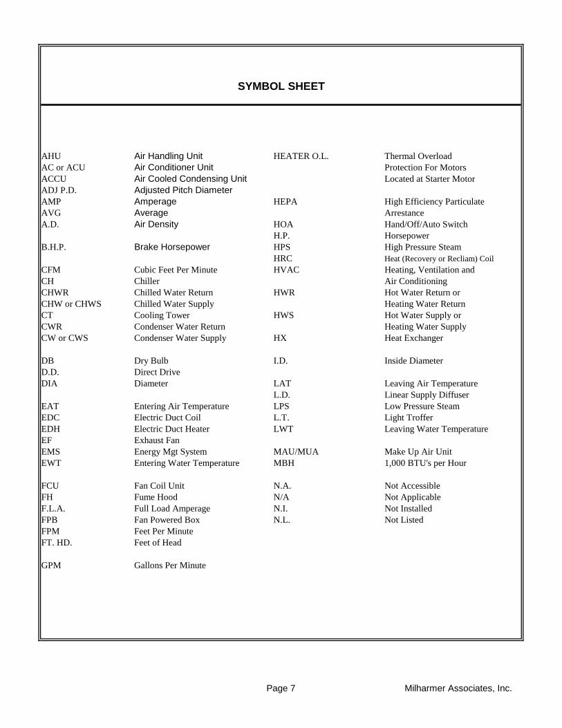
AHU Air Handling Unit HEATER O.L. Thermal Overload
AC or ACU Air Conditioner Unit Protection For Motors
ACCU Air Cooled Condensing Unit Located at Starter Motor
ADJ P.D. Adjusted Pitch Diameter
AMP Amperage HEPA High Efficiency Particulate
AVG Average Arrestance
A.D. Air Density HOA Hand/Off/Auto Switch
H.P. Horsepower
B.H.P. Brake Horsepower HPS High Pressure Steam
HRC Heat (Recovery or Recliam) Coil
CFM Cubic Feet Per Minute HVAC Heating, Ventilation and
CH Chiller Air Conditioning
CHWR Chilled Water Return HWR Hot Water Return or
CHW or CHWS Chilled Water Supply Heating Water Return
CT Cooling Tower HWS Hot Water Supply or
CWR Condenser Water Return Heating Water Supply
CW or CWS Condenser Water Supply HX Heat Exchanger
DB Dry Bulb I.D. Inside Diameter
D.D. Direct Drive
DIA Diameter LAT Leaving Air Temperature
L.D. Linear Supply Diffuser
EAT Entering Air Temperature LPS Low Pressure Steam
EDC Electric Duct Coil L.T. Light Troffer
EDH Electric Duct Heater LWT Leaving Water Temperature
EF Exhaust Fan
EMS Energy Mgt System MAU/MUA Make Up Air Unit
EWT Entering Water Temperature MBH 1,000 BTU's per Hour
FCU Fan Coil Unit N.A. Not Accessible
FH Fume Hood N/A Not Applicable
F.L.A. Full Load Amperage N.I. Not Installed
FPB Fan Powered Box N.L. Not Listed
FPM Feet Per Minute
FT. HD. Feet of Head
GPM Gallons Per Minute
SYMBOL SHEET
Page 7 Milharmer Associates, Inc.

O.D. Outside Diameter TAB Testing, Adjusting, and Balancing
OA Min Outside Air Minimum TSP Total Static Pressure
OAT Outside Air Total TP Thermally Protected
PF Power Factor UH Unit Heater
PHC Preheat Coil
PH Phase(s) V Volts
PSI Pounds Per Square Inch VAV Variable Air Volume
P.T. Pitot Traverse VD Volume Damper
VFD Variable Frequency Drive
RA Return Air VP Velocity Pressure
RF Return Air Fan
R.G. Return Grille W Watts
RHC Reheat Coil WB Wet Bulb
RPM Revolutions per Minute W.D. Water Density
W.G. Water Guage
SA Supply Air
SAT Supply Air Temperature F Degrees Fahrenheit
S.D. Supply Diffuser
SEF Smoke Exhaust Fan ΔP Differential (Delta) Pressure or
SF (AIR) Supply Fan Pressure Drop
S.F.(Elect) Service Factors
SHC Steam Heating Coil ΔT Differential (Delta) Temperature,
S.P. "W.C." Static Pressure Net Temperature
Measured in Inches of Decrease or Increase
Water Column # PSI or Pounds Per Square Inch
Decrease or Increase
SYMBOL SHEET CONTINUED
Page 8 Milharmer Associates, Inc.

Project:
Address:
Date: Project No.
The following is the report for J. Michael Ruane Judicial Center. A survey was performed
on AHU-1 thru AHU-11 and the toilet exhaust fans. In addition to the testing, we worked
with the ATC contractor to calibrate the air flow stations and we have listed deficiencies
below that were found during the testing. Testing on the Air Handling Units was
performed with the VAV Boxes overridden to the full cooling positions and the Outside
Air Damper set to it minimum position with the DCV system overridden.
1. AHU-1 thru 4 were all tested and found to be within design parameters and
all airflow measuring stations were tested and calibrated with the ATC contractor.
2. AHU-5 thru AHU-8 were tested with the VAV boxes set to the full cooling position and
all 4 units tested well below design for supply and return airflow. Additionally, the
outside air flow stations are in a bad location and should be re-located to allow for more
uniform readings. Both supply and return airflow stations calibrated fine.
3. AHU-9 was tested with the VAV boxes set to the full cooling position and the unit
is well below design airflow. The outside air flow station also will not calibrate and
should be investigated further by the ATC contractor or AFMS manufacturer.
4. AHU-10 was tested and found to be within design parameters and all airflow
measuring stations were tested and calibrated with the ATC contractor.
5. AHU-11 was tested and found to be below design airflow but the return fan was
under performing due to bad fan belts which need to be replaced prior to re-testing
the unit.
Overall, the HVAC equipment appears to be running at design or capable of achieving
design airflow throughout the facility. The units that are low on design airflow need to
be investigated further to determine if there is some blockage in the duct work or
if there are control issues preventing the units from reaching design airflow. Based
on present readings, all Air Handling Units appear to have sufficient capacity to increase
the filter efficiency to MERV 13/14.
J. Michael Ruane Judicial Center
58 Federal St., Salem, MA
11/13/2020 20-548
REPORT SUMMARY
Page 9 Milharmer Associates, Inc.

Project:
Address:
Date: Project No.
UNIT SUPPLY RETURN OUTSIDE AIR
AHU-1 6,055 CFM 3,303 CFM 2,152 CFM
AHU-2 6,025 CFM 3,616 CFM 2,409 CFM
AHU-3 4,365 CFM 2,151 CFM 2,214 CFM
AHU-4 11,616 CFM 7,280 CFM 4,336 CFM
AHU-5 15,887 CFM 8,807 CFM 7,080 CFM
AHU-6 20,175 CFM 13,065 CFM 7,110 CFM
AHU-7 17,962 CFM 10,747 CFM 7,215 CFM
AHU-8 19,412 CFM 12,242 CFM 7,170 CFM
AHU-9 22,225 CFM 15,433 CFM 6,795 CFM
AHU-10 4,488 CFM 2,837 CFM 1,651 CFM
AHU-11 11,450 CFM NA NA
UNIT EXHAUST
F-14 5,853 CFM
F-15 4,872 CFM
F-16 4,850 CFM
F-17 9,912 CFM
F-20 13,825 CFM
F-21 15,776 CFM
F-22 19,250 CFM
F-23 17,999 CFM
F-18 18,919 CFM
F-19 4,634 CFM
F-27 NA
F-24 6,070 CFM
F-25 4,894 CFM
F-26 1,756 CFM
F-28 239 CFM
F-29 1,740 CFM
AIR HANDLING UNITS
FANS
J. Michael Ruane Judicial Center
58 Federal St., Salem, MA
11/13/2020 20-548
REPORT SUMMARY
Page 10 Milharmer Associates, Inc.

Project: J. Michael Ruane Judicial Center
Address: 58 Federal St., Salem, MA
Date: Project No.
AHU-1 F-14
Mech. 6400 Mech 6400
TESTED TESTED
GE BALDOR
215T 184T
10 5
NA NA
1.15 1.15
460/3 460/3
9.9 4.9
1800 1800
60 Hz 60 Hz
VFD Protected VFD Protected
VFD Protected VFD Protected
TESTED TESTED
6055 *1
3903 5853 *2
1950
2152
-2.07 -1.35
1.67 0.58
NA NA
3.74 1.93
TESTED TESTED
NA INLINE
BK35 4.25" OD
1 3/8 QT 1 1/8
BK77 INLINE
1 7/16 INLINE
BX77x1 AP58x2
27.6 INLINE
FIXED FIXED
Comments:
11/13/2020 20-548
FAN DATA SHEET
Serves / Location:
FAN NO. FAN NO.
Manufacturer: CARRIER GREENHECK
Courtrooms Return for AHU-1
Model Number: 39MN14C011KF311XGS QEI-20-1-50
Size: 14 NL
Serial Number: 4309U23149 11887851
MOTOR DESIGN DESIGN
Manufacturer: NL NL
Frame Number: NL NL
Horsepower: 10 5
Brake Horsepower: 7.2 2.2
Safety Factor: NL NL
Volts/Phase: 460/3 460/3
Motor Amperage: 12.2 6.6
Motor RPM: 1760 1750
Speeds: VFD VFD
Heater Size: NL NL
Heater Amps.: NL NL
FAN DESIGN DESIGN
Supply Air CFM: 6000
Return Air CFM: 3900 5850
Exhaust Air CFM: 1950
Outside Air CFM: 2100
Suction Pressure: NL NL
Discharge Pressure: NL NL
Fan Static Pressure: 5.0" NL
External Pressure: NL 1.5"
RPM DESIGN DESIGN
Fan RPM: NL NL
Motor Drive: NL NL
Motor Size/Bore: NL NL
Fan Drive: NL NL
Turns Open: NL NL
*1 At 55.2 Hz
*2 At 60 Hz.
Fan Size/Bore: NL NL
Belt Size / Number: NL NL
Shafts C-C: NL NL
Page 11 Milharmer Associates, Inc.
Project:
Address:
Date: Project No.
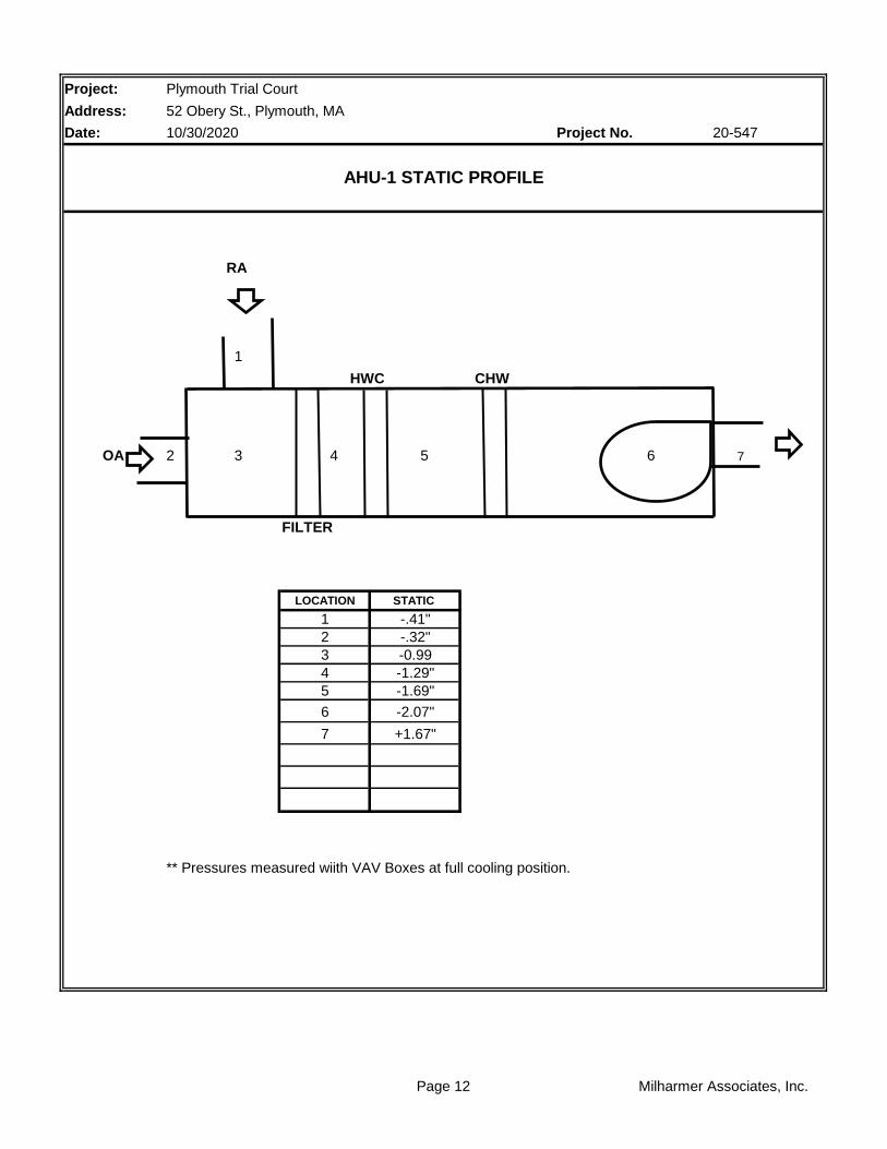
RA
1
HWC CHW
OA 2 3 4 5 6 7
FILTER
LOCATION STATIC
1 -.41"
2 -.32"
3 -0.99
4 -1.29"
5 -1.69"
6 -2.07"
7 +1.67"
** Pressures measured wiith VAV Boxes at full cooling position.
Plymouth Trial Court
52 Obery St., Plymouth, MA
10/30/2020 20-547
AHU-1 STATIC PROFILE
Page 12 Milharmer Associates, Inc.

Project:
Address:
Date: Project No.
SYSTEM: AHU-1 TRAVERSE NUMBER : T1
Supply TRAVERSE LOCATION: Mech 6400
DUCT SIZE (ROUND) " DIAMETER Sq Ft = 0.00
DUCT SIZE (RECT.) 22 " WIDTH x 14 " DEPTH Sq Ft = 2.14
AIR DENSITY DATA
STATIC PRESS @ CL: NA InWg. DESIGN CFM = NL
DUCT AIR TEMP : 70 Deg F ACTUAL CFM = 3395
BAROMETRIC PRESS : 29.92 In Hg. SCFM= 3396
AIR DENSITY RATIO CORRECTION = 1.00
SCFM CORRECTION FACTOR 1.00
ACTUAL DENSITY 0.075
TEST HOLE 1 2 3 4 5 6 7
A 1593 1703 1714 1533 1593 1674
B 1462 1643 1830 1724 1759 1518
C 936 1127 1732 1702 1712 1597
D
E
F
G
H
I
NO. OF READINGS = 18 AVERAGE FPM = 1586
J
K
L
M
N
O
P
Q
R
TECHNICIAN: David Burns
TRAVERSE DATA
J. Michael Ruane Judicial Center
58 Federal St., Salem, MA
11/13/2020 20-548
Page 13 Milharmer Associates, Inc.
Project:
Address:
Date: Project No.
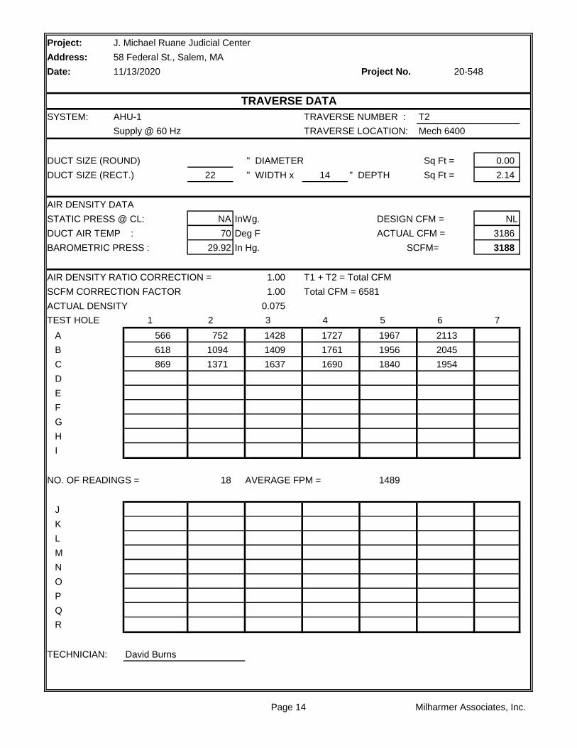
SYSTEM: AHU-1 TRAVERSE NUMBER : T2
Supply @ 60 Hz TRAVERSE LOCATION: Mech 6400
DUCT SIZE (ROUND) " DIAMETER Sq Ft = 0.00
DUCT SIZE (RECT.) 22 " WIDTH x 14 " DEPTH Sq Ft = 2.14
AIR DENSITY DATA
STATIC PRESS @ CL: NA InWg. DESIGN CFM = NL
DUCT AIR TEMP : 70 Deg F ACTUAL CFM = 3186
BAROMETRIC PRESS : 29.92 In Hg. SCFM= 3188
AIR DENSITY RATIO CORRECTION = 1.00 T1 + T2 = Total CFM
SCFM CORRECTION FACTOR 1.00 Total CFM = 6581
ACTUAL DENSITY 0.075
TEST HOLE 1 2 3 4 5 6 7
A 566 752 1428 1727 1967 2113
B 618 1094 1409 1761 1956 2045
C 869 1371 1637 1690 1840 1954
D
E
F
G
H
I
NO. OF READINGS = 18 AVERAGE FPM = 1489
J
K
L
M
N
O
P
Q
R
TECHNICIAN: David Burns
J. Michael Ruane Judicial Center
58 Federal St., Salem, MA
11/13/2020 20-548
TRAVERSE DATA
Page 14 Milharmer Associates, Inc.

Project:
Address:
Date: Project No.
SYSTEM: AHU-1 TRAVERSE NUMBER : T1
Return TRAVERSE LOCATION: Mech 6400
DUCT SIZE (ROUND) " DIAMETER Sq Ft = 0.00
DUCT SIZE (RECT.) 34 " WIDTH x 20 " DEPTH Sq Ft = 4.72
AIR DENSITY DATA
STATIC PRESS @ CL: -0.48 InWg. DESIGN CFM = 3900
DUCT AIR TEMP : 70 Deg F ACTUAL CFM = 3903
BAROMETRIC PRESS : 29.92 In Hg. SCFM= 3901
AIR DENSITY RATIO CORRECTION = 1.00
SCFM CORRECTION FACTOR 1.00
ACTUAL DENSITY 0.075
TEST HOLE 1 2 3 4 5 6 7
A 500 761 572 543 326 511 297
B 1068 1227 955 679 776 826 710
C 1085 1196 1280 1028 1249 1391 1017
D
E
F
G
H
I
NO. OF READINGS = 27 AVERAGE FPM = 827
J 309 202
K 748 671
L 1358 1044
M
N
O
P
Q
R
TECHNICIAN: David Burns
J. Michael Ruane Judicial Center
58 Federal St., Salem, MA
11/13/2020 20-548
TRAVERSE DATA
Page 15 Milharmer Associates, Inc.

Project:
Address:
Date: Project No.
SYSTEM: AHU-1 TRAVERSE NUMBER : T1
Outside Air TRAVERSE LOCATION: Mech 6400
DUCT SIZE (ROUND) " DIAMETER Sq Ft = 0.00
DUCT SIZE (RECT.) 60 " WIDTH x 16 " DEPTH Sq Ft = 6.67
AIR DENSITY DATA
STATIC PRESS @ CL: NA InWg. DESIGN CFM = 2100
DUCT AIR TEMP : 70 Deg F ACTUAL CFM = 2152
BAROMETRIC PRESS : 29.92 In Hg. SCFM= 2153
AIR DENSITY RATIO CORRECTION = 1.00 AFMS Cal = 0.851
SCFM CORRECTION FACTOR 1.00
ACTUAL DENSITY 0.075
TEST HOLE 1 2 3 4 5 6 7
A 564 531 496 518
B 373 355 368 418
C 86 51 37 77
D
E
F
G
H
I
NO. OF READINGS = 12 AVERAGE FPM = 323
J
K
L
M
N
O
P
Q
R
TECHNICIAN: David Burns
J. Michael Ruane Judicial Center
58 Federal St., Salem, MA
11/13/2020 20-548
VELGRID TRAVERSE DATA
Page 16 Milharmer Associates, Inc.

Project:
Address:
Date: Project No.
SYSTEM: F-14 TRAVERSE NUMBER : T1
TRAVERSE LOCATION: Mech 6400
DUCT SIZE (ROUND) " DIAMETER Sq Ft = 0.00
DUCT SIZE (RECT.) 34 " WIDTH x 20 " DEPTH Sq Ft = 4.72
AIR DENSITY DATA
STATIC PRESS @ CL: 0.91 InWg. DESIGN CFM = 5850
DUCT AIR TEMP : 70 Deg F ACTUAL CFM = 5853
BAROMETRIC PRESS : 29.92 In Hg. SCFM= 5870
AIR DENSITY RATIO CORRECTION = 1.00 AFMS Cal = 0.984
SCFM CORRECTION FACTOR 1.00
ACTUAL DENSITY 0.075
TEST HOLE 1 2 3 4 5 6 7
A 465 448 1141 857 825 489 767
B 1121 1065 1840 1442 1025 1164 1227
C 1996 1525 1794 1907 1564 1873 2098
D
E
F
G
H
I
NO. OF READINGS = 27 AVERAGE FPM = 1240
J 303 1628
K 1007 1601
L 1558 753
M
N
O
P
Q
R
TECHNICIAN: David Burns
J. Michael Ruane Judicial Center
58 Federal St., Salem, MA
11/13/2020 20-548
TRAVERSE DATA
Page 17 Milharmer Associates, Inc.
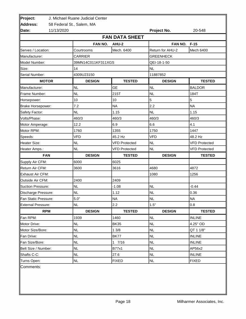
Project: J. Michael Ruane Judicial Center
Address: 58 Federal St., Salem, MA
Date: Project No.
AHU-2 F-15
Mech. 6400 Mech 6400
TESTED TESTED
GE BALDOR
215T 184T
10 5
NA NA
1.15 1.15
460/3 460/3
6.9 4.1
1355 1447
45.2 Hz 48.2 Hz
VFD Protected VFD Protected
VFD Protected VFD Protected
TESTED TESTED
6025
3616 4872
1256
2409
-1.08 -0.44
1.12 0.36
NA NA
2.2 0.8
TESTED TESTED
1460 INLINE
BK35 4.25" OD
1 3/8 QT 1 1/8"
BK77 INLINE
1 7/16 INLINE
B77x1 AP56x2
27.6 INLINE
FIXED FIXED
Comments:
Turns Open: NL NL
Belt Size / Number: NL NL
Shafts C-C: NL NL
Fan Drive: NL NL
Fan Size/Bore: NL NL
Motor Drive: NL NL
Motor Size/Bore: NL NL
RPM DESIGN DESIGN
Fan RPM: 1939 NL
Fan Static Pressure: 5.0" NL
External Pressure: NL 1.5"
Suction Pressure: NL NL
Discharge Pressure: NL NL
Exhaust Air CFM: 1080
Outside Air CFM: 2400
Supply Air CFM: 6000
Return Air CFM: 3600 4680
Heater Amps.: NL NL
FAN DESIGN DESIGN
Speeds: VFD VFD
Heater Size: NL NL
Motor Amperage: 12.2 6.6
Motor RPM: 1760 1750
Safety Factor: NL NL
Volts/Phase: 460/3 460/3
Horsepower: 10 5
Brake Horsepower: 7.2 2.2
Manufacturer: NL NL
Frame Number: NL NL
Serial Number: 4309U23150 11887852
MOTOR DESIGN DESIGN
Size: 14 NL
Serves / Location: Courtrooms Return for AHU-2
Manufacturer: CARRIER GREENHECK
11/13/2020 20-548
FAN DATA SHEET
FAN NO. FAN NO.
Model Number: 39MN14C011KF311XGS QEI-18-1-50
Page 18 Milharmer Associates, Inc.

Project:
Address:
Date: Project No.
RA
1
HWC CHW
OA 2 3 4 5 6 7
FILTER
LOCATION STATIC
1 -.11"
2 -.12"
3 -.31"
4 -.62"
5 -.80"
6 -1.08"
7 +1.12"
** Pressures measured wiith VAV Boxes at full cooling position.
Plymouth Trial Court
52 Obery St., Plymouth, MA
10/30/2020 20-547
AHU-2 STATIC PROFILE
Page 19 Milharmer Associates, Inc.
Project:
Address:
Date: Project No.
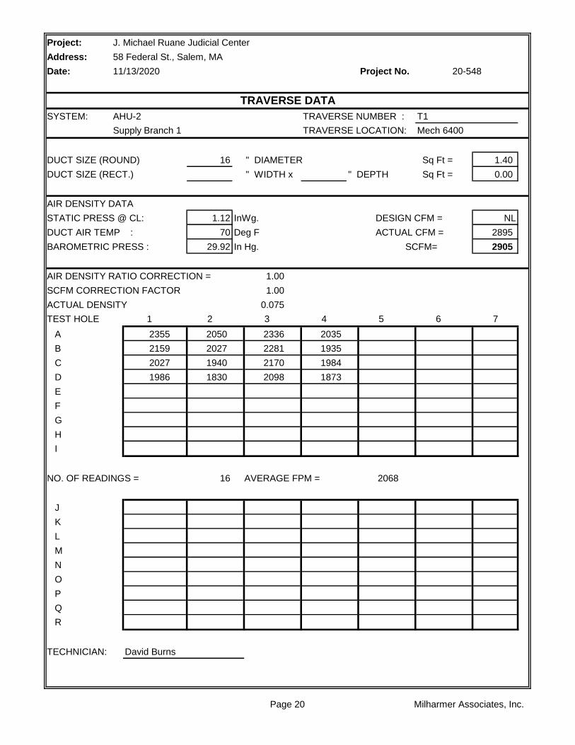
SYSTEM: AHU-2 TRAVERSE NUMBER : T1
Supply Branch 1 TRAVERSE LOCATION: Mech 6400
DUCT SIZE (ROUND) 16 " DIAMETER Sq Ft = 1.40
DUCT SIZE (RECT.) " WIDTH x " DEPTH Sq Ft = 0.00
AIR DENSITY DATA
STATIC PRESS @ CL: 1.12 InWg. DESIGN CFM = NL
DUCT AIR TEMP : 70 Deg F ACTUAL CFM = 2895
BAROMETRIC PRESS : 29.92 In Hg. SCFM= 2905
AIR DENSITY RATIO CORRECTION = 1.00
SCFM CORRECTION FACTOR 1.00
ACTUAL DENSITY 0.075
TEST HOLE 1 2 3 4 5 6 7
A 2355 2050 2336 2035
B 2159 2027 2281 1935
C 2027 1940 2170 1984
D 1986 1830 2098 1873
E
F
G
H
I
NO. OF READINGS = 16 AVERAGE FPM = 2068
J
K
L
M
N
O
P
Q
R
TECHNICIAN: David Burns
J. Michael Ruane Judicial Center
58 Federal St., Salem, MA
11/13/2020 20-548
TRAVERSE DATA
Page 20 Milharmer Associates, Inc.

Project:
Address:
Date: Project No.
SYSTEM: AHU-2 TRAVERSE NUMBER : T2
Supply Branch 2 TRAVERSE LOCATION: Mech 6400
DUCT SIZE (ROUND) " DIAMETER Sq Ft = 0.00
DUCT SIZE (RECT.) 20 " WIDTH x 16 " DEPTH Sq Ft = 2.22
AIR DENSITY DATA
STATIC PRESS @ CL: 1.44 InWg. DESIGN CFM = NL
DUCT AIR TEMP : 70 Deg F ACTUAL CFM = 3130
BAROMETRIC PRESS : 29.92 In Hg. SCFM= 3143
AIR DENSITY RATIO CORRECTION = 1.00 T1 + T2 = Total CFM
SCFM CORRECTION FACTOR 1.00 Total CFM = 6025
ACTUAL DENSITY 0.075
TEST HOLE 1 2 3 4 5 6 7
A 1470 1369 1268 1547 1719
B 1376 1208 1179 1539 1699
C 1496 1274 1177 1391 1435
D
E
F
G
H
I
NO. OF READINGS = 15 AVERAGE FPM = 1410
J
K
L
M
N
O
P
Q
R
TECHNICIAN: David Burns
J. Michael Ruane Judicial Center
58 Federal St., Salem, MA
11/13/2020 20-548
TRAVERSE DATA
Page 21 Milharmer Associates, Inc.
Project:
Address:
Date: Project No.
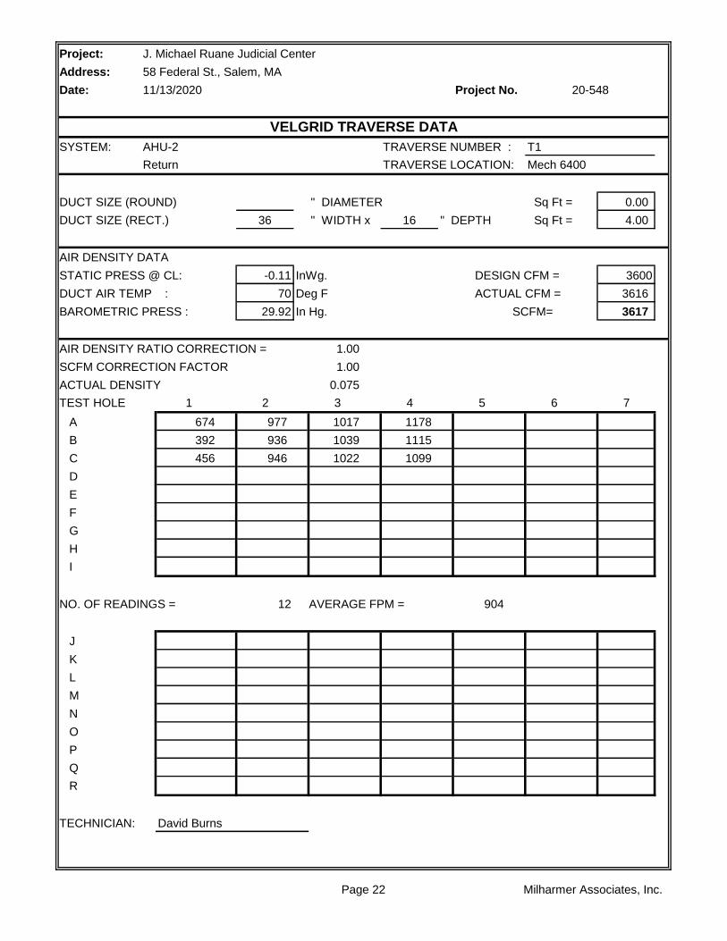
SYSTEM: AHU-2 TRAVERSE NUMBER : T1
Return TRAVERSE LOCATION: Mech 6400
DUCT SIZE (ROUND) " DIAMETER Sq Ft = 0.00
DUCT SIZE (RECT.) 36 " WIDTH x 16 " DEPTH Sq Ft = 4.00
AIR DENSITY DATA
STATIC PRESS @ CL: -0.11 InWg. DESIGN CFM = 3600
DUCT AIR TEMP : 70 Deg F ACTUAL CFM = 3616
BAROMETRIC PRESS : 29.92 In Hg. SCFM= 3617
AIR DENSITY RATIO CORRECTION = 1.00
SCFM CORRECTION FACTOR 1.00
ACTUAL DENSITY 0.075
TEST HOLE 1 2 3 4 5 6 7
A 674 977 1017 1178
B 392 936 1039 1115
C 456 946 1022 1099
D
E
F
G
H
I
NO. OF READINGS = 12 AVERAGE FPM = 904
J
K
L
M
N
O
P
Q
R
TECHNICIAN: David Burns
J. Michael Ruane Judicial Center
58 Federal St., Salem, MA
11/13/2020 20-548
VELGRID TRAVERSE DATA
Page 22 Milharmer Associates, Inc.

Project:
Address:
Date: Project No.
SYSTEM: AHU-2 TRAVERSE NUMBER : T1
Outside Air TRAVERSE LOCATION: Mech 6400
DUCT SIZE (ROUND) " DIAMETER Sq Ft = 0.00
DUCT SIZE (RECT.) 60 " WIDTH x 16 " DEPTH Sq Ft = 6.67
AIR DENSITY DATA
STATIC PRESS @ CL: -0.027 InWg. DESIGN CFM = 2400
DUCT AIR TEMP : 70 Deg F ACTUAL CFM = 2408
BAROMETRIC PRESS : 29.92 In Hg. SCFM= 2410
AIR DENSITY RATIO CORRECTION = 1.00 AFMS = 1.203
SCFM CORRECTION FACTOR 1.00
ACTUAL DENSITY 0.075
TEST HOLE 1 2 3 4 5 6 7
A 383 394 414 387
B 355 344 362 347
C 278 301 389 379
D
E
F
G
H
I
NO. OF READINGS = 12 AVERAGE FPM = 361
J
K
L
M
N
O
P
Q
R
TECHNICIAN: David Burns
J. Michael Ruane Judicial Center
58 Federal St., Salem, MA
11/13/2020 20-548
VELGRID TRAVERSE DATA
Page 23 Milharmer Associates, Inc.

Project:
Address:
Date: Project No.
SYSTEM: F-15 TRAVERSE NUMBER : T1
TRAVERSE LOCATION: Mech 6400
DUCT SIZE (ROUND) " DIAMETER Sq Ft = 0.00
DUCT SIZE (RECT.) 36 " WIDTH x 16 " DEPTH Sq Ft = 4.00
AIR DENSITY DATA
STATIC PRESS @ CL: NA InWg. DESIGN CFM = 4650
DUCT AIR TEMP : 70 Deg F ACTUAL CFM = 4872
BAROMETRIC PRESS : 29.92 In Hg. SCFM= 4875
AIR DENSITY RATIO CORRECTION = 1.00 AFMS Cal = 1.295
SCFM CORRECTION FACTOR 1.00
ACTUAL DENSITY 0.075
TEST HOLE 1 2 3 4 5 6 7
A 1474 1510 1545 1282 1541 1417
B 1171 1170 1084 1142 1260 1329
C 911 867 1006 875 1129 1213
D
E
F
G
H
I
NO. OF READINGS = 18 AVERAGE FPM = 1218
J
K
L
M
N
O
P
Q
R
TECHNICIAN: David Burns
J. Michael Ruane Judicial Center
58 Federal St., Salem, MA
11/13/2020 20-548
TRAVERSE DATA
Page 24 Milharmer Associates, Inc.

Project: J. Michael Ruane Judicial Center
Address: 58 Federal St., Salem, MA
Date: Project No.
AHU-3 F-16
Mech. 6100 Mech 6100
TESTED TESTED
GE BALDOR
215T 184T
10 5
NA NA
1.15 1.15
460/3 460/3
7 4.2
1800 1536
60 Hz 51.2 Hz
VFD Protected VFD Protected
VFD Protected VFD Protected
TESTED TESTED
4365
2151 4853
2214
-1.24 -0.59
1.14 0.07
NA NA
2.38 0.66
TESTED TESTED
1932 INLINE
BK77 4.5" OD
1 3/8 QT 1 1/8"
BK70H INLINE
H1 7/16 INLINE
BX74x1 AP56x2
27.3 INLINE
FIXED FIXED
Comments:
Turns Open: NL NL
Belt Size / Number: NL NL
Shafts C-C: NL NL
Fan Drive: NL NL
Fan Size/Bore: NL NL
Motor Drive: NL NL
Motor Size/Bore: NL NL
RPM DESIGN DESIGN
Fan RPM: 1932 NL
Fan Static Pressure: 5.0" NL
External Pressure: NL 1.5"
Suction Pressure: NL NL
Discharge Pressure: NL NL
Exhaust Air CFM:
Outside Air CFM: 2200
Supply Air CFM: 6000
Return Air CFM: 3800 4850
Heater Amps.: NL NL
FAN DESIGN DESIGN
Speeds: VFD VFD
Heater Size: NL NL
Motor Amperage: 12.2 6.6
Motor RPM: 1760 1750
Safety Factor: NL NL
Volts/Phase: 460/3 460/3
Horsepower: 10 5
Brake Horsepower: 7.2 2.2
Manufacturer: NL NL
Frame Number: NL NL
Serial Number: 4309U23151 11887853
MOTOR DESIGN DESIGN
Size: 14 NL
Serves / Location: Courtrooms Return for AHU-3
Manufacturer: CARRIER GREENHECK
11/13/2020 20-548
FAN DATA SHEET
FAN NO. FAN NO.
Model Number: 39MN14CD11KF411XGS QEI-18-1-60
Page 25 Milharmer Associates, Inc.

Project:
Address:
Date: Project No.
RA
1
HWC CHW
OA 2 3 4 5 6 7
FILTER
LOCATION STATIC
1 -.11"
2 -.10"
3 -.38"
4 -.60"
5 -.77"
6 -1.24"
7 +1.14"
** Pressures measured wiith VAV Boxes at full cooling position.
Plymouth Trial Court
52 Obery St., Plymouth, MA
10/30/2020 20-547
AHU-3 STATIC PROFILE
Page 26 Milharmer Associates, Inc.

Project:
Address:
Date: Project No.
SYSTEM: AHU-3 TRAVERSE NUMBER : T1
Supply TRAVERSE LOCATION: Mech 6100
DUCT SIZE (ROUND) " DIAMETER Sq Ft =
DUCT SIZE (RECT.) 30 " WIDTH x 16 " DEPTH Sq Ft = 3.33
AIR DENSITY DATA
STATIC PRESS @ CL: 1.14 InWg. DESIGN CFM = 6000
DUCT AIR TEMP : 70 Deg F ACTUAL CFM = 4365
BAROMETRIC PRESS : 29.92 In Hg. SCFM= 4380
AIR DENSITY RATIO CORRECTION = 1.00 AFMS = .875
SCFM CORRECTION FACTOR 1.00
ACTUAL DENSITY 0.075
TEST HOLE 1 2 3 4 5 6 7
A 1462 1363 1254 1338 1052 1300 1510
B 1582 1291 1310 1293 1238 1225 1335
C 1616 1212 1171 1074 1111 1198 1245
D
E
F
G
H
I
NO. OF READINGS = 24 AVERAGE FPM = 1311
J 1468
K 1530
L 1276
M
N
O
P
Q
R
TECHNICIAN: David Burns
J. Michael Ruane Judicial Center
58 Federal St., Salem, MA
11/13/2020 20-548
TRAVERSE DATA
Page 27 Milharmer Associates, Inc.

Project:
Address:
Date: Project No.
SYSTEM: AHU-3 TRAVERSE NUMBER : T1
Return TRAVERSE LOCATION: Mech 6100
DUCT SIZE (ROUND) " DIAMETER Sq Ft = 0.00
DUCT SIZE (RECT.) 38 " WIDTH x 16 " DEPTH Sq Ft = 4.22
AIR DENSITY DATA
STATIC PRESS @ CL: -0.09 InWg. DESIGN CFM = 3800
DUCT AIR TEMP : 70 Deg F ACTUAL CFM = 2152
BAROMETRIC PRESS : 29.92 In Hg. SCFM= 2153
AIR DENSITY RATIO CORRECTION = 1.00 AFMS = NA
SCFM CORRECTION FACTOR 1.00
ACTUAL DENSITY 0.075
TEST HOLE 1 2 3 4 5 6 7
A 778 812 785 693
B 868 831 857 814
C 533 527 518 512
D 529 564 558 534
E 109 278 259 117
F 116 229 279 133
G
H
I
NO. OF READINGS = 24 AVERAGE FPM = 510
J
K
L
M
N
O
P
Q
R
TECHNICIAN: David Burns
J. Michael Ruane Judicial Center
58 Federal St., Salem, MA
11/13/2020 20-548
TRAVERSE DATA
Page 28 Milharmer Associates, Inc.

Project:
Address:
Date: Project No.
SYSTEM: AHU-3 TRAVERSE NUMBER : T1
Outside Air TRAVERSE LOCATION: OSA Intake
DUCT SIZE (ROUND) " DIAMETER Sq Ft = 0.00
DUCT SIZE (RECT.) 48 " WIDTH x 18 " DEPTH Sq Ft = 6.00
AIR DENSITY DATA
STATIC PRESS @ CL: -0.07 InWg. DESIGN CFM = 2200
DUCT AIR TEMP : 70 Deg F ACTUAL CFM = 2214
BAROMETRIC PRESS : 29.92 In Hg. SCFM= 2215
AIR DENSITY RATIO CORRECTION = 1.00 AFMS = .715
SCFM CORRECTION FACTOR 1.00
ACTUAL DENSITY 0.075
TEST HOLE 1 2 3 4 5 6 7
A 312 352 460 498 526 520 404
B 289 438 357 346 496 320 501
C 343 342 409 261 275 394 495
D 492 283 294 241 246 311 251
E
F
G
H
I
NO. OF READINGS = 32 AVERAGE FPM = 369
J 227
K 400
L 397
M 263
N
O
P
Q
R
TECHNICIAN: David Burns
J. Michael Ruane Judicial Center
58 Federal St., Salem, MA
11/13/2020 20-548
TRAVERSE DATA
Page 29 Milharmer Associates, Inc.

Project:
Address:
Date: Project No.
SYSTEM: F-16 TRAVERSE NUMBER : T1
TRAVERSE LOCATION: Exhaust Duct
DUCT SIZE (ROUND) " DIAMETER Sq Ft = 0.00
DUCT SIZE (RECT.) 38 " WIDTH x 16 " DEPTH Sq Ft = 4.22
AIR DENSITY DATA
STATIC PRESS @ CL: 0.003 InWg. DESIGN CFM = 4850
DUCT AIR TEMP : 70 Deg F ACTUAL CFM = 4853
BAROMETRIC PRESS : 29.92 In Hg. SCFM= 4856
AIR DENSITY RATIO CORRECTION = 1.00 AFMS = 1.129
SCFM CORRECTION FACTOR 1.00
ACTUAL DENSITY 0.075
TEST HOLE 1 2 3 4 5 6 7
A 260 0 147 627 878 1321 1627
B 192 165 492 690 937 1121 1559
C 209 381 626 1029 1268 1641 1825
D
E
F
G
H
I
NO. OF READINGS = 30 AVERAGE FPM = 1150
J 1889 2099 1824
K 1752 1935 2098
L 1859 1999 2056
M
N
O
P
Q
R
TECHNICIAN: David Burns
J. Michael Ruane Judicial Center
58 Federal St., Salem, MA
11/13/2020 20-548
TRAVERSE DATA
Page 30 Milharmer Associates, Inc.

Project: J. Michael Ruane Judicial Center
Address: 58 Federal St., Salem, MA
Date: Project No.
AHU-4 F-17
Mech. 6100 Mech 6100
TESTED TESTED
GE BALDOR
256T 213T
20 7.5
NA NA
1.15 1.15
460/3 460/3
17.1 6.4
1800 1770
60 Hz 59 Hz
VFD Protected VFD Protected
VFD Protected VFD Protected
TESTED TESTED
11616
7280 9912
2630
4336
-2.51 -0.77
1.1 0.84
NA NA
3.61 1.61
TESTED TESTED
1387 INLINE
2B5V66 4" OD
B1 5/8 Q1 1 3/8
2BK90 INLINE
1 7/16 INLINE
BX90x2 BX654x2
34.1 INLINE
FIXED FIXED
Comments:
Turns Open: NL NL
Belt Size / Number: NL NL
Shafts C-C: NL NL
Fan Drive: NL NL
Fan Size/Bore: NL NL
Motor Drive: NL NL
Motor Size/Bore: NL NL
RPM DESIGN DESIGN
Fan RPM: 1387 NL
Fan Static Pressure: 5.2" NL
External Pressure: NL 2.0"
Suction Pressure: NL NL
Discharge Pressure: NL NL
Exhaust Air CFM: 2800
Outside Air CFM: 3800
Supply Air CFM: 10800
Return Air CFM: 7000 9800
Heater Amps.: NL NL
FAN DESIGN DESIGN
Speeds: VFD VFD
Heater Size: NL NL
Motor Amperage: 23.7 9.6
Motor RPM: 1760 1770
Safety Factor: NL NL
Volts/Phase: 460/3 460/3
Horsepower: 20 7.5
Brake Horsepower: 13.3 4.6
Manufacturer: NL NL
Frame Number: NL NL
Serial Number: 4309U23152 1187854
MOTOR DESIGN DESIGN
Size: 25 NL
Serves / Location: Courtrooms Return for AHU-4
Manufacturer: CARRIER GREENHECK
11/13/2020 20-548
FAN DATA SHEET
FAN NO. FAN NO.
Model Number: 39MN25C011KF511XGS QEI-24-1-75
Page 31 Milharmer Associates, Inc.

Project:
Address:
Date: Project No.
RA
1
HWC CHW
OA 2 3 4 5 6 7
FILTER
LOCATION STATIC
1 -.52"
2 -.49"
3 -1.48"
4 -1.72"
5 -.2.14"
6 -2.51"
7 +1.10"
** Pressures measured wiith VAV Boxes at full cooling position.
Plymouth Trial Court
52 Obery St., Plymouth, MA
10/30/2020 20-547
AHU-4 STATIC PROFILE
Page 32 Milharmer Associates, Inc.

Project:
Address:
Date: Project No.
SYSTEM: AHU-4 TRAVERSE NUMBER : T1
Supply TRAVERSE LOCATION: Mech 6100
DUCT SIZE (ROUND) " DIAMETER Sq Ft = 0.00
DUCT SIZE (RECT.) 54 " WIDTH x 16 " DEPTH Sq Ft = 6.00
AIR DENSITY DATA
STATIC PRESS @ CL: 1.1 InWg. DESIGN CFM = 10800
DUCT AIR TEMP : 70 Deg F ACTUAL CFM = 11616
BAROMETRIC PRESS : 29.92 In Hg. SCFM= 11654
AIR DENSITY RATIO CORRECTION = 1.00 AFMS Cal = 1.096
SCFM CORRECTION FACTOR 1.00
ACTUAL DENSITY 0.075
TEST HOLE 1 2 3 4 5 6 7
A 2599 2672 2394 2379 1818 2425 2420
B 2041 2145 2230 2155 1390 2236 1932
C 1642 1695 1696 1399 1310 1340 1550
D
E
F
G
H
I
NO. OF READINGS = 27 AVERAGE FPM = 1936
J 2540 2420
K 1698 1606
L 1355 1169
M
N
O
P
Q
R
TECHNICIAN: David Burns
J. Michael Ruane Judicial Center
58 Federal St., Salem, MA
11/13/2020 20-548
TRAVERSE DATA
Page 33 Milharmer Associates, Inc.

Project:
Address:
Date: Project No.
SYSTEM: AHU-4 TRAVERSE NUMBER : T1
Return TRAVERSE LOCATION: Mech 6100
DUCT SIZE (ROUND) " DIAMETER Sq Ft = 0.00
DUCT SIZE (RECT.) 36 " WIDTH x 30 " DEPTH Sq Ft = 7.50
AIR DENSITY DATA
STATIC PRESS @ CL: -0.85 InWg. DESIGN CFM = 7000
DUCT AIR TEMP : 70 Deg F ACTUAL CFM = 7282
BAROMETRIC PRESS : 29.92 In Hg. SCFM= 7271
AIR DENSITY RATIO CORRECTION = 1.00 AFMS Cal = NA
SCFM CORRECTION FACTOR 1.00
ACTUAL DENSITY 0.075
TEST HOLE 1 2 3 4 5 6 7
A 366 0 224 0 0 0 0
B 1155 0 0 0 0 0 0
C 2144 544 410 393 774 1223 1047
D 1796 1572 1347 1400 1390 1274 1498
E 1920 2280 2340 2518 1894 1887 1961
F
G
H
I
NO. OF READINGS = 45 AVERAGE FPM = 971
J 0 0
K 0 0
L 230 1632
M 1556 1760
N 1925 2193
O
P
Q
R
TECHNICIAN: David Burns
J. Michael Ruane Judicial Center
58 Federal St., Salem, MA
11/13/2020 20-548
TRAVERSE DATA
Page 34 Milharmer Associates, Inc.

Project:
Address:
Date: Project No.
SYSTEM: AHU-4 TRAVERSE NUMBER : T1
OSA TRAVERSE LOCATION: OSA Intake
DUCT SIZE (ROUND) " DIAMETER Sq Ft = 0.00
DUCT SIZE (RECT.) 48 " WIDTH x 30 " DEPTH Sq Ft = 10.00
AIR DENSITY DATA
STATIC PRESS @ CL: -0.37 InWg. DESIGN CFM = 3800
DUCT AIR TEMP : 70 Deg F ACTUAL CFM = 4336
BAROMETRIC PRESS : 29.92 In Hg. SCFM= 4335
AIR DENSITY RATIO CORRECTION = 1.00 AFMS Cal = 1.271
SCFM CORRECTION FACTOR 1.00 **AFMS fluctuating, unable
ACTUAL DENSITY 0.075 to calibrate properly.
TEST HOLE 1 2 3 4 5 6 7
A 474 438 427 388
B 470 454 429 406
C 467 455 442 485
D 371 366 383 483
E
F
G
H
I
NO. OF READINGS = 16 AVERAGE FPM = 434
J
K
L
M
N
O
P
Q
R
TECHNICIAN: David Burns
J. Michael Ruane Judicial Center
58 Federal St., Salem, MA
11/13/2020 20-548
VELGRID TRAVERSE DATA
Page 35 Milharmer Associates, Inc.

Project:
Address:
Date: Project No.
SYSTEM: F-17 TRAVERSE NUMBER : T1
TRAVERSE LOCATION: Mech 6100
DUCT SIZE (ROUND) " DIAMETER Sq Ft = 0.00
DUCT SIZE (RECT.) 48 " WIDTH x 24 " DEPTH Sq Ft = 8.00
AIR DENSITY DATA
STATIC PRESS @ CL: -1.21 InWg. DESIGN CFM = 9800
DUCT AIR TEMP : 70 Deg F ACTUAL CFM = 9912
BAROMETRIC PRESS : 29.92 In Hg. SCFM= 9888
AIR DENSITY RATIO CORRECTION = 1.00 AFMS Cal = 0.911
SCFM CORRECTION FACTOR 1.00
ACTUAL DENSITY 0.075
TEST HOLE 1 2 3 4 5 6 7
A 939 1014 1036 1023 1439 1229 1271
B 896 924 994 1061 1427 1234 1236
C 884 938 996 1162 1414 1271 1268
D 837 919 1001 1039 1377 1256 1265
E
F
G
H
I
NO. OF READINGS = 48 AVERAGE FPM = 1239
J 1242 1265 1438 1426 1968
K 1231 1269 1516 1389 1956
L 1256 1271 1537 1379 1727
M 1259 1251 1517 1382 842
N
O
P
Q
R
TECHNICIAN: David Burns
J. Michael Ruane Judicial Center
58 Federal St., Salem, MA
11/13/2020 20-548
TRAVERSE DATA
Page 36 Milharmer Associates, Inc.

Project: J. Michael Ruane Judicial Center
Address: 58 Federal St., Salem, MA
Date: Project No.
AHU-5 F-20
Mech 2250 Mech 2250
TESTED TESTED
*1 AO Smith
*1 S254T
*1 15
*1 NA
1.15 1.15
460/3 460/3
36.7 12
1722 1800
57.4 Hz 60 Hz
VFD Protected VFD Protected
VFD Protected VFD Protected
TESTED TESTED
15887
8807 13825
7080 *2
-1.1 -1.15
3.19 0.04
NA NA
4.29 1.19
TESTED TESTED
1134 INLINE
2B5V90 5.7" OD
B2 1/8 1 5/8
2B5V136 INLINE
B1 15/16 INLINE
5VX1320 x2 BP98x3
48" INLINE
FIXED FIXED
Comments:
Turns Open: NL NL
*1 No motor nameplate tag.
*2 AFMS not calibrating.
Belt Size / Number: NL NL
Shafts C-C: NL NL
Fan Drive: NL NL
Fan Size/Bore: NL NL
Motor Drive: NL NL
Motor Size/Bore: NL NL
RPM DESIGN DESIGN
Fan RPM: 1162 NL
Fan Static Pressure: 5.5" NL
External Pressure: NL 1.5"
Suction Pressure: NL NL
Discharge Pressure: NL NL
Exhaust Air CFM:
Outside Air CFM: 7000
Supply Air CFM: 25000
Return Air CFM: 18000 20000
Heater Amps.: NL NL
FAN DESIGN DESIGN
Speeds: VFD VFD
Heater Size: NL NL
Motor Amperage: 52 18.9
Motor RPM: *1 1770
Safety Factor: NL NL
Volts/Phase: 460/3 460/3
Horsepower: 40 15
Brake Horsepower: 31.3 7.1
Manufacturer: NL NL
Frame Number: NL NL
Serial Number: 4309U23190 1187857
MOTOR DESIGN DESIGN
Size: 50 NL
Serves / Location: Admin Areas AHU-5 Return
Manufacturer: CARRIER GREENHECK
11/13/2020 20-548
FAN DATA SHEET
FAN NO. FAN NO.
Model Number: 39MN50C011KF622XGS QEI-36-1-150
Page 37 Milharmer Associates, Inc.

Project:
Address:
Date: Project No.
RA
1
HWC CHW
OA 2 3 4 5 6 7
FILTER
LOCATION STATIC
1 -.24"
2 -.32"
3 -.43"
4 -.65"
5 -.79"
6 -1.11"
7 +3.19"
** Pressures measured wiith VAV Boxes at full cooling position.
Plymouth Trial Court
52 Obery St., Plymouth, MA
10/30/2020 20-547
AHU-5 STATIC PROFILE
Page 38 Milharmer Associates, Inc.

Project:
Address:
Date: Project No.
SYSTEM: AHU-5 TRAVERSE NUMBER : T1
Supply TRAVERSE LOCATION: Mech 2250
DUCT SIZE (ROUND) " DIAMETER Sq Ft = 0.00
DUCT SIZE (RECT.) 60 " WIDTH x 30 " DEPTH Sq Ft = 12.50
AIR DENSITY DATA
STATIC PRESS @ CL: 3.79 InWg. DESIGN CFM = 25000
DUCT AIR TEMP : 70 Deg F ACTUAL CFM = 15887
BAROMETRIC PRESS : 29.92 In Hg. SCFM= 16044
AIR DENSITY RATIO CORRECTION = 1.01 AFMS Cal = 1.023
SCFM CORRECTION FACTOR 1.01
ACTUAL DENSITY 0.076
TEST HOLE 1 2 3 4 5 6 7
A 2022 1646 1629 1102 951 648 601
B 2086 1990 1836 1258 867 964 1435
C 1884 1773 1687 1266 881 819 905
D 1582 1274 1385 1165 773 909 1012
E 1140 1059 1182 1096 952 1058 987
F
G
H
I
NO. OF READINGS = 50 AVERAGE FPM = 1275
J 573 930 1241
K 1188 1051 1491
L 1269 1708 1710
M 1226 1542 1707
N 1323 1580 1404
O
P
Q
R
TECHNICIAN: David Burns
J. Michael Ruane Judicial Center
58 Federal St., Salem, MA
11/13/2020 20-548
TRAVERSE DATA
Page 39 Milharmer Associates, Inc.

Project:
Address:
Date: Project No.
SYSTEM: AHU-5 TRAVERSE NUMBER : T1
Return TRAVERSE LOCATION: Return Intake
DUCT SIZE (ROUND) " DIAMETER Sq Ft = 0.00
DUCT SIZE (RECT.) 60 " WIDTH x 30 " DEPTH Sq Ft = 12.50
AIR DENSITY DATA
STATIC PRESS @ CL: NA InWg. DESIGN CFM = 18000
DUCT AIR TEMP : 70 Deg F ACTUAL CFM = 8812
BAROMETRIC PRESS : 29.92 In Hg. SCFM= 8817
AIR DENSITY RATIO CORRECTION = 1.00
SCFM CORRECTION FACTOR 1.00
ACTUAL DENSITY 0.075
TEST HOLE 1 2 3 4 5 6 7
A 706 716 734 1083
B 1117 1063 631 644
C 188 379 586 608
D
E
F
G
H
I
NO. OF READINGS = 12 AVERAGE FPM = 705
J
K
L
M
N
O
P
Q
R
TECHNICIAN: David Burns
J. Michael Ruane Judicial Center
58 Federal St., Salem, MA
11/13/2020 20-548
VELGRID TRAVERSE DATA
Page 40 Milharmer Associates, Inc.

Project:
Address:
Date: Project No.
SYSTEM: AHU-5 TRAVERSE NUMBER : T1
Outside Air TRAVERSE LOCATION: OSA Intake
DUCT SIZE (ROUND) " DIAMETER Sq Ft = 0.00
DUCT SIZE (RECT.) 60 " WIDTH x 36 " DEPTH Sq Ft = 15.00
AIR DENSITY DATA
STATIC PRESS @ CL: NA InWg. DESIGN CFM = 7000
DUCT AIR TEMP : 70 Deg F ACTUAL CFM = 7080
BAROMETRIC PRESS : 29.92 In Hg. SCFM= 7084
AIR DENSITY RATIO CORRECTION = 1.00 AFMS = 0.761
SCFM CORRECTION FACTOR 1.00
ACTUAL DENSITY 0.075
TEST HOLE 1 2 3 4 5 6 7
A 312 535 706 753 306
B 677 275 797 609 519
C 488 -96 781 216 664
D 691 -87 806 -172 652
E
F
G
H
I
NO. OF READINGS = 20 AVERAGE FPM = 472
J
K
L
M
N
O
P
Q
R
TECHNICIAN: David Burns
J. Michael Ruane Judicial Center
58 Federal St., Salem, MA
11/13/2020 20-548
VELGRID TRAVERSE DATA
Page 41 Milharmer Associates, Inc.

Project:
Address:
Date: Project No.
SYSTEM: F-20 TRAVERSE NUMBER : T1
TRAVERSE LOCATION: Mech 2250 Exhaust
DUCT SIZE (ROUND) " DIAMETER Sq Ft = 0.00
DUCT SIZE (RECT.) 60 " WIDTH x 30 " DEPTH Sq Ft = 12.50
AIR DENSITY DATA
STATIC PRESS @ CL: NA InWg. DESIGN CFM = 20000
DUCT AIR TEMP : 70 Deg F ACTUAL CFM = 5013
BAROMETRIC PRESS : 29.92 In Hg. SCFM= 5015
AIR DENSITY RATIO CORRECTION = 1.00 AFMS = .864
SCFM CORRECTION FACTOR 1.00
ACTUAL DENSITY 0.075
TEST HOLE 1 2 3 4 5 6 7
A 476 689 575 586
B 406 387 404 559
C 174 153 129 276
D
E
F
G
H
I
NO. OF READINGS = 12 AVERAGE FPM = 401
J
K
L
M
N
O
P
Q
R
AHU-5 Return + F-20 Exhaust = Total CFM
TECHNICIAN: David Burns 8812 + 5013 = 13825 cfm.
J. Michael Ruane Judicial Center
58 Federal St., Salem, MA
11/13/2020 20-548
VELGRID TRAVERSE DATA
Page 42 Milharmer Associates, Inc.

Project: J. Michael Ruane Judicial Center
Address: 58 Federal St., Salem, MA
Date: Project No.
AHU-6 F-21
Mech 2250 Mech 2250
TESTED TESTED
*1 BALDOR
*1 254T
*1 15
*1 NA
1.15 1.15
460/3 460/3
38.9 11.2
1699 1800
56.6 Hz 60 Hz
VFD Protected VFD Protected
VFD Protected VFD Protected
TESTED TESTED
20175
13065 15776
7110 *2
-1.86 -1.54
3.99 0.37
NA NA
5.85 1.91
TESTED TESTED
1119 INLINE
2B5V90 5.7" OD
B2 1/8 1 5/8
2B5V136 INLINE
B1 15/16 INLINE
5VX1320 x2 BP98x3
48" INLINE
FIXED FIXED
Comments:
Turns Open: NL NL
*1 No motor nameplate tag.
*2 AFMS not calibrating.
Belt Size / Number: NL NL
Shafts C-C: NL NL
Fan Drive: NL NL
Fan Size/Bore: NL NL
Motor Drive: NL NL
Motor Size/Bore: NL NL
RPM DESIGN DESIGN
Fan RPM: NL NL
Fan Static Pressure: 5.5" NL
External Pressure: NL 1.5"
Suction Pressure: NL NL
Discharge Pressure: NL NL
Exhaust Air CFM:
Outside Air CFM: 7000
Supply Air CFM: 25000
Return Air CFM: 18000 20000
Heater Amps.: NL NL
FAN DESIGN DESIGN
Speeds: VFD VFD
Heater Size: NL NL
Motor Amperage: 52 17.7
Motor RPM: *1 1765
Safety Factor: NL NL
Volts/Phase: 460/3 460/3
Horsepower: 40 15
Brake Horsepower: 31.3 7.1
Manufacturer: NL NL
Frame Number: NL NL
Serial Number: 4309U23195 11887858
MOTOR DESIGN DESIGN
Size: 50 NL
Serves / Location: Admin Areas AHU-6 Return
Manufacturer: CARRIER GREENHECK
11/13/2020 20-548
FAN DATA SHEET
FAN NO. FAN NO.
Model Number: 39MN50C011F722XGS QEI-36-1-150
Page 43 Milharmer Associates, Inc.

Project:
Address:
Date: Project No.
RA
1
HWC CHW
OA 2 3 4 5 6 7
FILTER
LOCATION STATIC
1 -.52"
2 -.48"
3 -.90"
4 -1.17"
5 -1.41"
6 -1.86"
7 +3.99"
** Pressures measured wiith VAV Boxes at full cooling position.
Plymouth Trial Court
52 Obery St., Plymouth, MA
10/30/2020 20-547
AHU-6 STATIC PROFILE
Page 44 Milharmer Associates, Inc.

Project:
Address:
Date: Project No.
SYSTEM: AHU-6 TRAVERSE NUMBER : T1
Supply TRAVERSE LOCATION: Mech 2250
DUCT SIZE (ROUND) " DIAMETER Sq Ft = 0.00
DUCT SIZE (RECT.) 60 " WIDTH x 30 " DEPTH Sq Ft = 12.50
AIR DENSITY DATA
STATIC PRESS @ CL: NA InWg. DESIGN CFM = 25000
DUCT AIR TEMP : 70 Deg F ACTUAL CFM = 20175
BAROMETRIC PRESS : 29.92 In Hg. SCFM= 20186
AIR DENSITY RATIO CORRECTION = 1.00 AFMS = 1.059
SCFM CORRECTION FACTOR 1.00
ACTUAL DENSITY 0.075
TEST HOLE 1 2 3 4 5 6 7
A 2068 2116 1999 2113 1464 2014 2274
B 1881 1883 1839 1558 1937 1984 2373
C 1680 1677 1457 865 1137 832 1956
D 1273 1484 1268 792 544 858 1217
E 1102 1355 966 1012 620 907 1190
F
G
H
I
NO. OF READINGS = 50 AVERAGE FPM = 1614
J 2559 2568 2609
K 2352 2435 2331
L 1848 1730 1847
M 1232 1608 1760
N 1315 1417 1384
O
P
Q
R
TECHNICIAN: David Burns
J. Michael Ruane Judicial Center
58 Federal St., Salem, MA
11/13/2020 20-548
TRAVERSE DATA
Page 45 Milharmer Associates, Inc.

Project:
Address:
Date: Project No.
SYSTEM: AHU-6 TRAVERSE NUMBER : T1
Return TRAVERSE LOCATION: Return Intake
DUCT SIZE (ROUND) " DIAMETER Sq Ft = 0.00
DUCT SIZE (RECT.) 60 " WIDTH x 30 " DEPTH Sq Ft = 12.50
AIR DENSITY DATA
STATIC PRESS @ CL: NA InWg. DESIGN CFM = 18000
DUCT AIR TEMP : 70 Deg F ACTUAL CFM = 13063
BAROMETRIC PRESS : 29.92 In Hg. SCFM= 13070
AIR DENSITY RATIO CORRECTION = 1.00
SCFM CORRECTION FACTOR 1.00
ACTUAL DENSITY 0.075
TEST HOLE 1 2 3 4 5 6 7
A 1041 1037 1090 416
B 1374 1387 1281 535
C 1316 1336 863 867
D
E
F
G
H
I
NO. OF READINGS = 12 AVERAGE FPM = 1045
J
K
L
M
N
O
P
Q
R
TECHNICIAN: David Burns
J. Michael Ruane Judicial Center
58 Federal St., Salem, MA
11/13/2020 20-548
VELGRID TRAVERSE DATA
Page 46 Milharmer Associates, Inc.
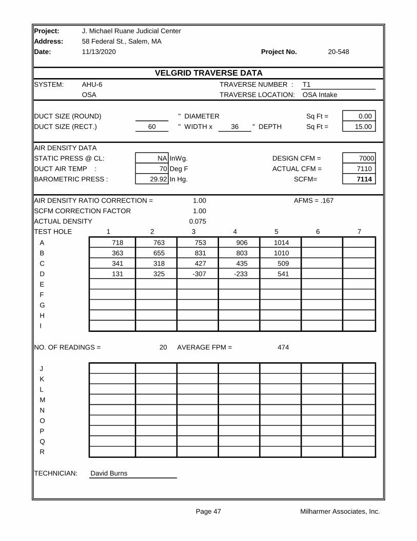
Project:
Address:
Date: Project No.
SYSTEM: AHU-6 TRAVERSE NUMBER : T1
OSA TRAVERSE LOCATION: OSA Intake
DUCT SIZE (ROUND) " DIAMETER Sq Ft = 0.00
DUCT SIZE (RECT.) 60 " WIDTH x 36 " DEPTH Sq Ft = 15.00
AIR DENSITY DATA
STATIC PRESS @ CL: NA InWg. DESIGN CFM = 7000
DUCT AIR TEMP : 70 Deg F ACTUAL CFM = 7110
BAROMETRIC PRESS : 29.92 In Hg. SCFM= 7114
AIR DENSITY RATIO CORRECTION = 1.00 AFMS = .167
SCFM CORRECTION FACTOR 1.00
ACTUAL DENSITY 0.075
TEST HOLE 1 2 3 4 5 6 7
A 718 763 753 906 1014
B 363 655 831 803 1010
C 341 318 427 435 509
D 131 325 -307 -233 541
E
F
G
H
I
NO. OF READINGS = 20 AVERAGE FPM = 474
J
K
L
M
N
O
P
Q
R
TECHNICIAN: David Burns
J. Michael Ruane Judicial Center
58 Federal St., Salem, MA
11/13/2020 20-548
VELGRID TRAVERSE DATA
Page 47 Milharmer Associates, Inc.

Project:
Address:
Date: Project No.
SYSTEM: F-21 TRAVERSE NUMBER : T1
TRAVERSE LOCATION: Mech 2250
DUCT SIZE (ROUND) " DIAMETER Sq Ft = 0.00
DUCT SIZE (RECT.) 60 " WIDTH x 30 " DEPTH Sq Ft = 12.50
AIR DENSITY DATA
STATIC PRESS @ CL: NA InWg. DESIGN CFM = 20000
DUCT AIR TEMP : 70 Deg F ACTUAL CFM = 2713
BAROMETRIC PRESS : 29.92 In Hg. SCFM= 2714
AIR DENSITY RATIO CORRECTION = 1.00 AFMS = 1.081
SCFM CORRECTION FACTOR 1.00
ACTUAL DENSITY 0.075
TEST HOLE 1 2 3 4 5 6 7
A 521 467 508 615
B 361 439 237 245
C -231 -174 -206 -179
D
E
F
G
H
I
NO. OF READINGS = 12 AVERAGE FPM = 217
J
K
L
M
N
O
P
Q
R
AHU-6 Return + F-21 Exhaust = Total CFM
TECHNICIAN: David Burns 13063 + 2713 = 15776 CFM
J. Michael Ruane Judicial Center
58 Federal St., Salem, MA
11/13/2020 20-548
VELGRID TRAVERSE DATA
Page 48 Milharmer Associates, Inc.

Project: J. Michael Ruane Judicial Center
Address: 58 Federal St., Salem, MA
Date: Project No.
AHU-7 F-22
Mech 2250 Mech 2250
TESTED TESTED
*1 BALDOR
*1 254T
*1 15
*1 NA
1.15 1.15
460/3 460/3
36 10.9
1662 1798
55.4 Hz 60 Hz
VFD Protected VFD Protected
VFD Protected VFD Protected
TESTED TESTED
17962
10747 19250
7215 *2
-1.56 -1.28
4.32 0.5
NA NA
5.88 1.78
TESTED TESTED
1119 INLINE
2B5V90 5.7" OD
B2 1/8 1 5/8
2B5V136 INLINE
B1 15/16 INLINE
5VX1320 x2 BP98x3
48" INLINE
FIXED FIXED
Comments:
Turns Open: NL NL
*1 No motor nameplate tag.
*2 AFMS not calibrating.
Belt Size / Number: NL NL
Shafts C-C: NL NL
Fan Drive: NL NL
Fan Size/Bore: NL NL
Motor Drive: NL NL
Motor Size/Bore: NL NL
RPM DESIGN DESIGN
Fan RPM: NL NL
Fan Static Pressure: 5.5" NL
External Pressure: NL 1.5"
Suction Pressure: NL NL
Discharge Pressure: NL NL
Exhaust Air CFM:
Outside Air CFM: 7000
Supply Air CFM: 25000
Return Air CFM: 18000 20000
Heater Amps.: NL NL
FAN DESIGN DESIGN
Speeds: VFD VFD
Heater Size: NL NL
Motor Amperage: 52 17.7
Motor RPM: *1 1765
Safety Factor: NL NL
Volts/Phase: 460/3 460/3
Horsepower: 40 15
Brake Horsepower: 31.3 7.1
Manufacturer: NL NL
Frame Number: NL NL
Serial Number: 4309U23194 11887859
MOTOR DESIGN DESIGN
Size: 50 NL
Serves / Location: Admin Areas AHU-7 Return
Manufacturer: CARRIER GREENHECK
11/13/2020 20-548
FAN DATA SHEET
FAN NO. FAN NO.
Model Number: 39MN50C011F722XGS QEI-36-1-150
Page 49 Milharmer Associates, Inc.

Project:
Address:
Date: Project No.
RA
1
HWC CHW
OA 2 3 4 5 6 7
FILTER
LOCATION STATIC
1 -.38"
2 -.41"
3 -..52"
4 -.79"
5 -1.06"
6 -1.56"
7 +4.32"
** Pressures measured wiith VAV Boxes at full cooling position.
Plymouth Trial Court
52 Obery St., Plymouth, MA
10/30/2020 20-547
AHU-7 STATIC PROFILE
Page 50 Milharmer Associates, Inc.

Project:
Address:
Date: Project No.
SYSTEM: AHU-7 TRAVERSE NUMBER : T1
Supply TRAVERSE LOCATION: Mech 2250
DUCT SIZE (ROUND) " DIAMETER Sq Ft = 0.00
DUCT SIZE (RECT.) 60 " WIDTH x 30 " DEPTH Sq Ft = 12.50
AIR DENSITY DATA
STATIC PRESS @ CL: 3.19 InWg. DESIGN CFM = 25000
DUCT AIR TEMP : 70 Deg F ACTUAL CFM = 17962
BAROMETRIC PRESS : 29.92 In Hg. SCFM= 18113
AIR DENSITY RATIO CORRECTION = 1.01 AFMS = 1.112
SCFM CORRECTION FACTOR 1.01
ACTUAL DENSITY 0.076
TEST HOLE 1 2 3 4 5 6 7
A 1691 1788 1603 1669 1737 1479 1981
B 1819 1701 1683 1789 1546 1622 1838
C 933 1045 1447 1246 1304 1342 1690
D 1296 821 345 422 1179 1152 1439
E 796 482 381 156 679 808 1275
F
G
H
I
NO. OF READINGS = 50 AVERAGE FPM = 1437
J 2003 1863 2100
K 2170 2289 2354
L 1909 1684 2066
M 1543 1666 1769
N 1281 1424 1524
O
P
Q
R
TECHNICIAN: David Burns
J. Michael Ruane Judicial Center
58 Federal St., Salem, MA
11/13/2020 20-548
TRAVERSE DATA
Page 51 Milharmer Associates, Inc.

Project:
Address:
Date: Project No.
SYSTEM: AHU-7 TRAVERSE NUMBER : T1
Return TRAVERSE LOCATION: Return Intake
DUCT SIZE (ROUND) " DIAMETER Sq Ft = 0.00
DUCT SIZE (RECT.) 60 " WIDTH x 30 " DEPTH Sq Ft = 12.50
AIR DENSITY DATA
STATIC PRESS @ CL: NA InWg. DESIGN CFM = 18000
DUCT AIR TEMP : 70 Deg F ACTUAL CFM = 10750
BAROMETRIC PRESS : 29.92 In Hg. SCFM= 10756
AIR DENSITY RATIO CORRECTION = 1.00
SCFM CORRECTION FACTOR 1.00
ACTUAL DENSITY 0.075
TEST HOLE 1 2 3 4 5 6 7
A 1128 1218 1174 1053
B 858 961 843 927
C 474 502 511 668
D
E
F
G
H
I
NO. OF READINGS = 12 AVERAGE FPM = 860
J
K
L
M
N
O
P
Q
R
TECHNICIAN: David Burns
J. Michael Ruane Judicial Center
58 Federal St., Salem, MA
11/13/2020 20-548
VELGRID TRAVERSE DATA
Page 52 Milharmer Associates, Inc.

Project:
Address:
Date: Project No.
SYSTEM: AHU-7 TRAVERSE NUMBER : T1
OSA TRAVERSE LOCATION: OSA Intake
DUCT SIZE (ROUND) " DIAMETER Sq Ft = 0.00
DUCT SIZE (RECT.) 60 " WIDTH x 36 " DEPTH Sq Ft = 15.00
AIR DENSITY DATA
STATIC PRESS @ CL: NA InWg. DESIGN CFM = 7000
DUCT AIR TEMP : 70 Deg F ACTUAL CFM = 7215
BAROMETRIC PRESS : 29.92 In Hg. SCFM= 7219
AIR DENSITY RATIO CORRECTION = 1.00 AFMS = .417
SCFM CORRECTION FACTOR 1.00
ACTUAL DENSITY 0.075
TEST HOLE 1 2 3 4 5 6 7
A 272 461 438 874 883
B 655 384 518 936 855
C 478 383 622 1001 672
D 580 -107 -164 -90 -36
E
F
G
H
I
NO. OF READINGS = 20 AVERAGE FPM = 481
J
K
L
M
N
O
P
Q
R
TECHNICIAN: David Burns
J. Michael Ruane Judicial Center
58 Federal St., Salem, MA
11/13/2020 20-548
VELGRID TRAVERSE DATA
Page 53 Milharmer Associates, Inc.

Project:
Address:
Date: Project No.
SYSTEM: F-22 TRAVERSE NUMBER : T1
TRAVERSE LOCATION: Mech 2250
DUCT SIZE (ROUND) " DIAMETER Sq Ft = 0.00
DUCT SIZE (RECT.) 60 " WIDTH x 30 " DEPTH Sq Ft = 12.50
AIR DENSITY DATA
STATIC PRESS @ CL: NA InWg. DESIGN CFM = 20000
DUCT AIR TEMP : 70 Deg F ACTUAL CFM = 8500
BAROMETRIC PRESS : 29.92 In Hg. SCFM= 8505
AIR DENSITY RATIO CORRECTION = 1.00 AFMS = 1.081
SCFM CORRECTION FACTOR 1.00
ACTUAL DENSITY 0.075
TEST HOLE 1 2 3 4 5 6 7
A 257 1274 1922 1578
B 512 674 693 724
C 184 115 109 116
D
E
F
G
H
I
NO. OF READINGS = 12 AVERAGE FPM = 680
J
K
L
M
N
O
P
Q
R
AHU-7 Return + F-22 Exhaust = Total CFM
TECHNICIAN: David Burns 10750 + 8500 = 19250 CFM
J. Michael Ruane Judicial Center
58 Federal St., Salem, MA
11/13/2020 20-548
VELGRID TRAVERSE DATA
Page 54 Milharmer Associates, Inc.

Project: J. Michael Ruane Judicial Center
Address: 58 Federal St., Salem, MA
Date: Project No.
AHU-8 F-23
Mech 2250 Mech 2250
TESTED TESTED
*1 BALDOR
*1 254T
*1 15
*1 NA
1.15 1.15
460/3 460/3
36.7 11.4
1722 1800
57.4 Hz 60 Hz
VFD Protected VFD Protected
VFD Protected VFD Protected
TESTED TESTED
19412
12242 17999
7170 *2
-0.99 -1.21
4.94 0.31
NA NA
5.88 1.52
TESTED TESTED
1162 INLINE
2B5V136 5.7" OD
B2 1/8 1 5/8
2B5V136 INLINE
B1 15/16 INLINE
5VX1320 x2 BP98x3
48" INLINE
FIXED FIXED
Comments:
Turns Open: NL NL
*1 No motor nameplate tag.
*2 AFMS not calibrating.
Belt Size / Number: NL NL
Shafts C-C: NL NL
Fan Drive: NL NL
Fan Size/Bore: NL NL
Motor Drive: NL NL
Motor Size/Bore: NL NL
RPM DESIGN DESIGN
Fan RPM: NL NL
Fan Static Pressure: 5.5" NL
External Pressure: NL 1.5"
Suction Pressure: NL NL
Discharge Pressure: NL NL
Exhaust Air CFM:
Outside Air CFM: 7000
Supply Air CFM: 25000
Return Air CFM: 18000 20000
Heater Amps.: NL NL
FAN DESIGN DESIGN
Speeds: VFD VFD
Heater Size: NL NL
Motor Amperage: 52 17.7
Motor RPM: *1 1765
Safety Factor: NL NL
Volts/Phase: 460/3 460/3
Horsepower: 40 15
Brake Horsepower: 31.3 7.1
Manufacturer: NL NL
Frame Number: NL NL
Serial Number: 4309U23191 11887860
MOTOR DESIGN DESIGN
Size: 50 NL
Serves / Location: Admin AHU-8 Return
Manufacturer: CARRIER GREENHECK
11/13/2020 20-548
FAN DATA SHEET
FAN NO. FAN NO.
Model Number: 39MN50C011F622XGS QEI-36-1-150
Page 55 Milharmer Associates, Inc.

Project:
Address:
Date: Project No.
SYSTEM: AHU-8 TRAVERSE NUMBER : T1
Supply TRAVERSE LOCATION: Mech 2250
DUCT SIZE (ROUND) " DIAMETER Sq Ft = 0.00
DUCT SIZE (RECT.) 60 " WIDTH x 30 " DEPTH Sq Ft = 12.50
AIR DENSITY DATA
STATIC PRESS @ CL: 2.8 InWg. DESIGN CFM = 25000
DUCT AIR TEMP : 70 Deg F ACTUAL CFM = 19412
BAROMETRIC PRESS : 29.92 In Hg. SCFM= 19557
AIR DENSITY RATIO CORRECTION = 1.01 AFMS = 1.013
SCFM CORRECTION FACTOR 1.01
ACTUAL DENSITY 0.076
TEST HOLE 1 2 3 4 5 6 7
A 3949 3573 4008 1569 0 4028 4015
B 2920 3521 3043 3335 3417 3336 3563
C 384 1590 1148 1712 1507 1212 1454
D 0 1036 0 584 646 747 0
E 0 0 0 0 0 482 414
F
G
H
I
NO. OF READINGS = 50 AVERAGE FPM = 1553
J 4002 3980 3897
K 3075 2016 2103
L 897 0 0
M 462 0 0
N 0 0 0
O
P
Q
R
TECHNICIAN: David Burns
J. Michael Ruane Judicial Center
58 Federal St., Salem, MA
11/13/2020 20-548
TRAVERSE DATA
Page 56 Milharmer Associates, Inc.

Project:
Address:
Date: Project No.
SYSTEM: AHU-8 TRAVERSE NUMBER : T1
Return TRAVERSE LOCATION: Return Intake
DUCT SIZE (ROUND) " DIAMETER Sq Ft = 0.00
DUCT SIZE (RECT.) 60 " WIDTH x 30 " DEPTH Sq Ft = 12.50
AIR DENSITY DATA
STATIC PRESS @ CL: NA InWg. DESIGN CFM = 18000
DUCT AIR TEMP : 70 Deg F ACTUAL CFM = 12238
BAROMETRIC PRESS : 29.92 In Hg. SCFM= 12245
AIR DENSITY RATIO CORRECTION = 1.00
SCFM CORRECTION FACTOR 1.00
ACTUAL DENSITY 0.075
TEST HOLE 1 2 3 4 5 6 7
A 1867 1952 1558 1483
B 166 257 316 1492
C 876 622 479 684
D
E
F
G
H
I
NO. OF READINGS = 12 AVERAGE FPM = 979
J
K
L
M
N
O
P
Q
R
TECHNICIAN: David Burns
J. Michael Ruane Judicial Center
58 Federal St., Salem, MA
11/13/2020 20-548
VELGRID TRAVERSE DATA
Page 57 Milharmer Associates, Inc.

Project:
Address:
Date: Project No.
SYSTEM: AHU-8 TRAVERSE NUMBER : T1
OSA TRAVERSE LOCATION: OSA Intake
DUCT SIZE (ROUND) " DIAMETER Sq Ft = 0.00
DUCT SIZE (RECT.) 60 " WIDTH x 36 " DEPTH Sq Ft = 15.00
AIR DENSITY DATA
STATIC PRESS @ CL: NA InWg. DESIGN CFM = 7000
DUCT AIR TEMP : 70 Deg F ACTUAL CFM = 7170
BAROMETRIC PRESS : 29.92 In Hg. SCFM= 7174
AIR DENSITY RATIO CORRECTION = 1.00 AFMS = .175
SCFM CORRECTION FACTOR 1.00
ACTUAL DENSITY 0.075
TEST HOLE 1 2 3 4 5 6 7
A 687 713 864 923 778
B 896 1034 314 328 626
C 686 969 577 549 603
D -334 -236 -249 -194 26
E
F
G
H
I
NO. OF READINGS = 20 AVERAGE FPM = 478
J
K
L
M
N
O
P
Q
R
TECHNICIAN: David Burns
J. Michael Ruane Judicial Center
58 Federal St., Salem, MA
11/13/2020 20-548
VELGRID TRAVERSE DATA
Page 58 Milharmer Associates, Inc.

Project:
Address:
Date: Project No.
SYSTEM: F-23 TRAVERSE NUMBER : T1
TRAVERSE LOCATION: Mech 2250
DUCT SIZE (ROUND) " DIAMETER Sq Ft = 0.00
DUCT SIZE (RECT.) 60 " WIDTH x 30 " DEPTH Sq Ft = 12.50
AIR DENSITY DATA
STATIC PRESS @ CL: NA InWg. DESIGN CFM = 20000
DUCT AIR TEMP : 70 Deg F ACTUAL CFM = 5762
BAROMETRIC PRESS : 29.92 In Hg. SCFM= 5765
AIR DENSITY RATIO CORRECTION = 1.00 AFMS = 1.259
SCFM CORRECTION FACTOR 1.00
ACTUAL DENSITY 0.075
TEST HOLE 1 2 3 4 5 6 7
A 892 953 959 1009
B 584 638 696 723
C -211 -309 -174 -225
D
E
F
G
H
I
NO. OF READINGS = 12 AVERAGE FPM = 461
J
K
L
M
N
O
P
Q
R
AHU-8 Return + F-23 Exhaust = Total CFM
TECHNICIAN: David Burns 12237 + 5762 = 17999 CFM
J. Michael Ruane Judicial Center
58 Federal St., Salem, MA
11/13/2020 20-548
VELGRID TRAVERSE DATA
Page 59 Milharmer Associates, Inc.

Project: J. Michael Ruane Judicial Center
Address: 58 Federal St., Salem, MA
Date: Project No.
AHU-9 F-18
Mech 4600 Mech 4600
TESTED TESTED
GE BALDOR
326T 256T
50 20
NA NA
1.15 1.15
460/3 460/3
36.8 15.4
1798 1800
60 Hz 60 Hz
VFD Protected VFD Protected
VFD Protected VFD Protected
TESTED TESTED
22225
15433 18919
6795
-3.12 -1.26
2.67 1.05
NA NA
5.79 2.31
TESTED TESTED
993 INLINE
2B5V90 6" OD
B2 1/8 1 5/8
2B5V160 INLINE
B2 3/16 INLINE
5VX1400x2 BX106x3
50" INLINE
FIXED FIXED
Comments:
Turns Open: NL NL
*1 AFMS not reading airflow properly or tracking changes in flow.
Belt Size / Number: NL NL
Shafts C-C: NL NL
Fan Drive: NL NL
Fan Size/Bore: NL NL
Motor Drive: NL NL
Motor Size/Bore: NL NL
RPM DESIGN DESIGN
Fan RPM: 989 NL
Fan Static Pressure: 5.2" NL
External Pressure: NL 1.5"
Suction Pressure: NL NL
Discharge Pressure: NL NL
Exhaust Air CFM:
Outside Air CFM: 6800
Supply Air CFM: 29000
Return Air CFM: 22200 26000
Heater Amps.: NL NL
FAN DESIGN DESIGN
Speeds: VFD VFD
Heater Size: NL NL
Motor Amperage: 57.9 23.5
Motor RPM: 1760 1765
Safety Factor: NL NL
Volts/Phase: 460/3 460/3
Horsepower: 50 20
Brake Horsepower: 34.8 12
Manufacturer: NL NL
Frame Number: NL NL
Serial Number: 4309U23198
MOTOR DESIGN DESIGN
Size: 50 NL
Serves / Location: Admin AHU-9 Return
Manufacturer: CARRIER GREENHECK
11/13/2020 20-548
FAN DATA SHEET
FAN NO. FAN NO.
Model Number: 39MN61C011F833XGS
Page 60 Milharmer Associates, Inc.

Project:
Address:
Date: Project No.
RA
1
HWC CHW
OA 2 3 4 5 6 7
FILTER
LOCATION STATIC
1 -.38"
2 -.41"
3 -..52"
4 -.79"
5 -1.06"
6 -1.56"
7 +4.32"
** Pressures measured wiith VAV Boxes at full cooling position.
Plymouth Trial Court
52 Obery St., Plymouth, MA
10/30/2020 20-547
AHU-7 STATIC PROFILE
Page 61 Milharmer Associates, Inc.
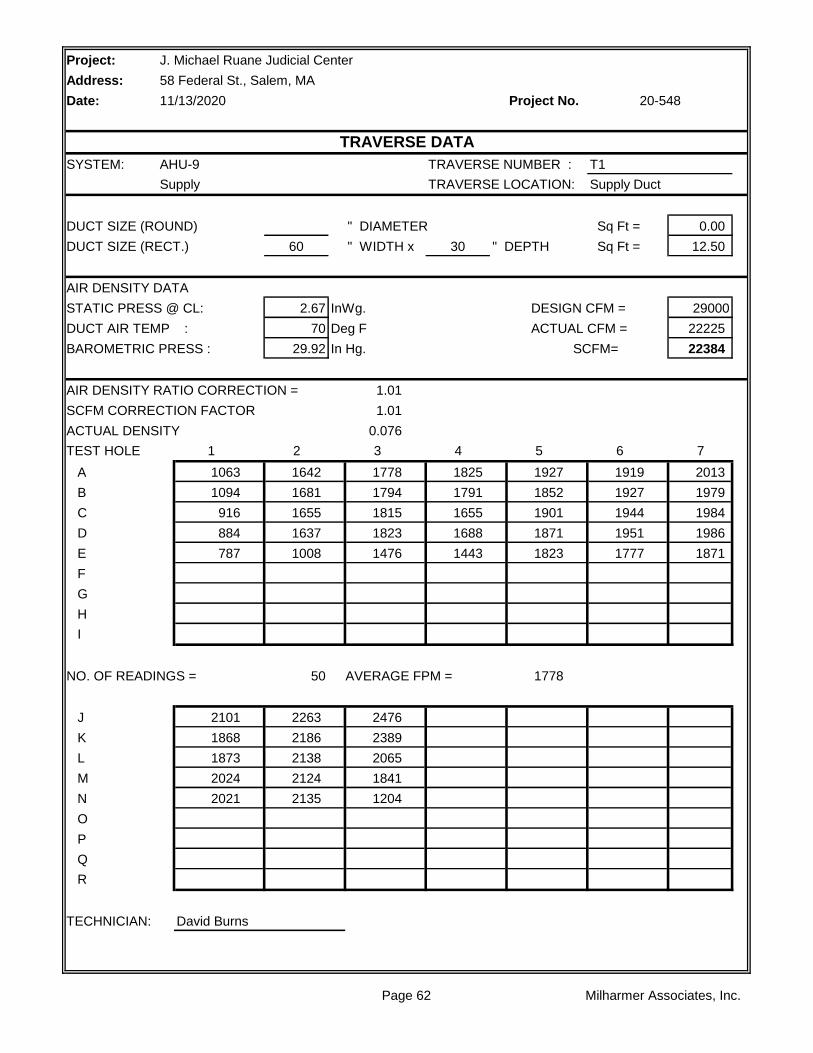
Project:
Address:
Date: Project No.
SYSTEM: AHU-9 TRAVERSE NUMBER : T1
Supply TRAVERSE LOCATION: Supply Duct
DUCT SIZE (ROUND) " DIAMETER Sq Ft = 0.00
DUCT SIZE (RECT.) 60 " WIDTH x 30 " DEPTH Sq Ft = 12.50
AIR DENSITY DATA
STATIC PRESS @ CL: 2.67 InWg. DESIGN CFM = 29000
DUCT AIR TEMP : 70 Deg F ACTUAL CFM = 22225
BAROMETRIC PRESS : 29.92 In Hg. SCFM= 22384
AIR DENSITY RATIO CORRECTION = 1.01
SCFM CORRECTION FACTOR 1.01
ACTUAL DENSITY 0.076
TEST HOLE 1 2 3 4 5 6 7
A 1063 1642 1778 1825 1927 1919 2013
B 1094 1681 1794 1791 1852 1927 1979
C 916 1655 1815 1655 1901 1944 1984
D 884 1637 1823 1688 1871 1951 1986
E 787 1008 1476 1443 1823 1777 1871
F
G
H
I
NO. OF READINGS = 50 AVERAGE FPM = 1778
J 2101 2263 2476
K 1868 2186 2389
L 1873 2138 2065
M 2024 2124 1841
N 2021 2135 1204
O
P
Q
R
TECHNICIAN: David Burns
J. Michael Ruane Judicial Center
58 Federal St., Salem, MA
11/13/2020 20-548
TRAVERSE DATA
Page 62 Milharmer Associates, Inc.

Project:
Address:
Date: Project No.
SYSTEM: AHU-9 TRAVERSE NUMBER : T1
Return TRAVERSE LOCATION: Return Intake
DUCT SIZE (ROUND) " DIAMETER Sq Ft = 0.00
DUCT SIZE (RECT.) 48 " WIDTH x 44 " DEPTH Sq Ft = 14.67
AIR DENSITY DATA
STATIC PRESS @ CL: NA InWg. DESIGN CFM = 22200
DUCT AIR TEMP : 70 Deg F ACTUAL CFM = 15433
BAROMETRIC PRESS : 29.92 In Hg. SCFM= 15442
AIR DENSITY RATIO CORRECTION = 1.00
SCFM CORRECTION FACTOR 1.00
ACTUAL DENSITY 0.075
TEST HOLE 1 2 3 4 5 6 7
A 996 1031 1074 1281 1245 1064
B 884 1024 1111 1224 1256 981
C 868 969 1115 1178 1253 859
D 885 906 1038 1137 1197 667
E
F
G
H
I
NO. OF READINGS = 24 AVERAGE FPM = 1052
J
K
L
M
N
O
P
Q
R
TECHNICIAN: David Burns
J. Michael Ruane Judicial Center
58 Federal St., Salem, MA
11/13/2020 20-548
VELGRID TRAVERSE DATA
Page 63 Milharmer Associates, Inc.

Project:
Address:
Date: Project No.
SYSTEM: AHU-9 TRAVERSE NUMBER : T1
OSA TRAVERSE LOCATION: OSA Intake
DUCT SIZE (ROUND) " DIAMETER Sq Ft = 0.00
DUCT SIZE (RECT.) 108 " WIDTH x 30 " DEPTH Sq Ft = 22.50
AIR DENSITY DATA
STATIC PRESS @ CL: NA InWg. DESIGN CFM = 6800
DUCT AIR TEMP : 70 Deg F ACTUAL CFM = 6795
BAROMETRIC PRESS : 29.92 In Hg. SCFM= 6799
AIR DENSITY RATIO CORRECTION = 1.00 AFMS = .071
SCFM CORRECTION FACTOR 1.00
ACTUAL DENSITY 0.075
TEST HOLE 1 2 3 4 5 6 7
A 296 317 302 307 314 333
B 254 306 319 328 325 341
C 202 287 300 345 292 367
D 196 243 303 336 289 352
E
F
G
H
I
NO. OF READINGS = 24 AVERAGE FPM = 302
J
K
L
M
N
O
P
Q
R
TECHNICIAN: David Burns
J. Michael Ruane Judicial Center
58 Federal St., Salem, MA
11/13/2020 20-548
VELGRID TRAVERSE DATA
Page 64 Milharmer Associates, Inc.

Project:
Address:
Date: Project No.
SYSTEM: F-18 TRAVERSE NUMBER : T1
TRAVERSE LOCATION:
DUCT SIZE (ROUND) " DIAMETER Sq Ft = 0.00
DUCT SIZE (RECT.) 72 " WIDTH x 30 " DEPTH Sq Ft = 15.00
AIR DENSITY DATA
STATIC PRESS @ CL: NA InWg. DESIGN CFM = 26000
DUCT AIR TEMP : 70 Deg F ACTUAL CFM = 18919
BAROMETRIC PRESS : 29.92 In Hg. SCFM= 18929
AIR DENSITY RATIO CORRECTION = 1.00 AFMS = 1.259
SCFM CORRECTION FACTOR 1.00
ACTUAL DENSITY 0.075
TEST HOLE 1 2 3 4 5 6 7
A 1341 1671 1613 1673 1481 2202 1830
B 1777 1797 1737 1552 1361 2052 1661
C 1745 1867 1682 1589 1362 1937 1437
D 1705 1729 1716 1665 1593 2025 1539
E 1673 1631 1658 1688 1344 2203 1670
F
G
H
I
NO. OF READINGS = 50 AVERAGE FPM = 1261
J 540 1149 0
K 80 520 0
L 161 0 0
M 178 0 0
N 462 481 285
O
P
Q
R
TECHNICIAN: David Burns
J. Michael Ruane Judicial Center
58 Federal St., Salem, MA
11/13/2020 20-548
VELGRID TRAVERSE DATA
Page 65 Milharmer Associates, Inc.

Project: J. Michael Ruane Judicial Center
Address: 58 Federal St., Salem, MA
Date: Project No.
AHU-10 F-19
TESTED TESTED
GE BALDOR
215T 182T
10 3
NA NA
1.15 1.15
460/3 460/3
7.9 2.6
1800 1556
60 Hz 51.9 Hz
VFD Protected VFD Protected
VFD Protected VFD Protected
TESTED TESTED
4488
2837 4634
1651
-1.63 -0.78
1.1 0.05
NA NA
NA 0.83
TESTED TESTED
2455 INLINE
BK90 3.5" OD
1 3/8 QTX 1 1/8
BK65H INLINE
H1 3/16 INLINE
BX70x1 A55x2
24.6 INLINE
FIXED FIXED
Comments:
Turns Open: NL NL
Belt Size / Number: NL NL
Shafts C-C: NL NL
Fan Drive: NL NL
Fan Size/Bore: NL NL
Motor Drive: NL NL
Motor Size/Bore: NL NL
RPM DESIGN DESIGN
Fan RPM: 2455 NL
Fan Static Pressure: 5.0" NL
External Pressure: NL 1.5"
Suction Pressure: NL NL
Discharge Pressure: NL NL
Exhaust Air CFM:
Outside Air CFM: 1650
Supply Air CFM: 4600
Return Air CFM: 2950 4200
Heater Amps.: NL NL
FAN DESIGN DESIGN
Speeds: VFD VFD
Heater Size: NL NL
Motor Amperage: 12.2 4
Motor RPM: 1760 1755
Safety Factor: NL NL
Volts/Phase: 460/3 460/3
Horsepower: 10 3
Brake Horsepower: 6 1.6
Manufacturer: NL NL
Frame Number: NL NL
Serial Number: 4309023153 11887856
MOTOR DESIGN DESIGN
Size: 50 NL
Serves / Location: AHU-10 Return
Manufacturer: CARRIER GREENHECK
11/13/2020 20-548
FAN DATA SHEET
FAN NO. FAN NO.
Model Number: 39MN1C011KF911XGS QEI-18-1-30
Page 66 Milharmer Associates, Inc.

Project:
Address:
Date: Project No.
RA
1
HWC CHW
OA 2 3 4 5 6 7
FILTER
LOCATION STATIC
1 -.26"
2 -.33"
3 -..52"
4 -.88"
5 -1.12"
6 -1.63"
7 +1.10"
** Pressures measured wiith VAV Boxes at full cooling position.
Plymouth Trial Court
52 Obery St., Plymouth, MA
10/30/2020 20-547
AHU-10 STATIC PROFILE
Page 67 Milharmer Associates, Inc.

Project:
Address:
Date: Project No.
SYSTEM: AHU-10 TRAVERSE NUMBER : T1
Supply TRAVERSE LOCATION: Supply Duct
DUCT SIZE (ROUND) " DIAMETER Sq Ft = 0.00
DUCT SIZE (RECT.) 24 " WIDTH x 16 " DEPTH Sq Ft = 2.67
AIR DENSITY DATA
STATIC PRESS @ CL: 1.1 InWg. DESIGN CFM = 4600
DUCT AIR TEMP : 70 Deg F ACTUAL CFM = 4488
BAROMETRIC PRESS : 29.92 In Hg. SCFM= 4503
AIR DENSITY RATIO CORRECTION = 1.00
SCFM CORRECTION FACTOR 1.00
ACTUAL DENSITY 0.075
TEST HOLE 1 2 3 4 5 6 7
A 1004 1134 1324 1728 2009 2068
B 1067 1386 1560 1690 1894 2131
C 1501 1483 1821 1839 2033 2168
D 1167 1517 1800 2047 1827 2154
E
F
G
H
I
NO. OF READINGS = 24 AVERAGE FPM = 1681
J
K
L
M
N
O
P
Q
R
TECHNICIAN: David Burns
J. Michael Ruane Judicial Center
58 Federal St., Salem, MA
11/13/2020 20-548
TRAVERSE DATA
Page 68 Milharmer Associates, Inc.

Project:
Address:
Date: Project No.
SYSTEM: AHU-10 TRAVERSE NUMBER : T1
Return TRAVERSE LOCATION: Return Intake
DUCT SIZE (ROUND) " DIAMETER Sq Ft = 0.00
DUCT SIZE (RECT.) 34 " WIDTH x 16 " DEPTH Sq Ft = 3.78
AIR DENSITY DATA
STATIC PRESS @ CL: -0.3 InWg. DESIGN CFM = 2950
DUCT AIR TEMP : 70 Deg F ACTUAL CFM = 2846
BAROMETRIC PRESS : 29.92 In Hg. SCFM= 2846
AIR DENSITY RATIO CORRECTION = 1.00
SCFM CORRECTION FACTOR 1.00
ACTUAL DENSITY 0.075
TEST HOLE 1 2 3 4 5 6 7
A 618 1534 1495 1563 1572 1387 595
B 1513 1311 1393 1295 1438 1512 328
C 855 1003 832 612 444 626 788
D 259 142 233 0 130 203 309
E
F
G
H
I
NO. OF READINGS = 36 AVERAGE FPM = 754
J 518 619
K 541 480
L 213 131
M 373 278
N
O
P
Q
R
TECHNICIAN: David Burns
J. Michael Ruane Judicial Center
58 Federal St., Salem, MA
11/13/2020 20-548
TRAVERSE DATA
Page 69 Milharmer Associates, Inc.

Project:
Address:
Date: Project No.
SYSTEM: AHU-10 TRAVERSE NUMBER : T1
OSA TRAVERSE LOCATION: OSA Intake
DUCT SIZE (ROUND) " DIAMETER Sq Ft = 0.00
DUCT SIZE (RECT.) 30 " WIDTH x 20 " DEPTH Sq Ft = 4.17
Damper @ 2.5V
AIR DENSITY DATA
STATIC PRESS @ CL: 0.06 InWg. DESIGN CFM = 1650
DUCT AIR TEMP : 70 Deg F ACTUAL CFM = 1651
BAROMETRIC PRESS : 29.92 In Hg. SCFM= 1652
AIR DENSITY RATIO CORRECTION = 1.00
SCFM CORRECTION FACTOR 1.00
ACTUAL DENSITY 0.075
TEST HOLE 1 2 3 4 5 6 7
A 1938 1239 1186 1449 1480 1416 1096
B 0 683 0 526 0 333 0
C 0 0 0 0 0 0 0
D 0 0 0 0 0 0 0
E
F
G
H
I
NO. OF READINGS = 32 AVERAGE FPM = 396
J 884
K 431
L 0
M 0
N
O
P
Q
R
TECHNICIAN: David Burns
J. Michael Ruane Judicial Center
58 Federal St., Salem, MA
11/13/2020 20-548
TRAVERSE DATA
Page 70 Milharmer Associates, Inc.

Project:
Address:
Date: Project No.
SYSTEM: F-19 TRAVERSE NUMBER : T1
TRAVERSE LOCATION: F-19 Intake
DUCT SIZE (ROUND) " DIAMETER Sq Ft = 0.00
DUCT SIZE (RECT.) 34 " WIDTH x 16 " DEPTH Sq Ft = 3.78
AIR DENSITY DATA
STATIC PRESS @ CL: -0.66 InWg. DESIGN CFM = 4200
DUCT AIR TEMP : 70 Deg F ACTUAL CFM = 4634
BAROMETRIC PRESS : 29.92 In Hg. SCFM= 4629
AIR DENSITY RATIO CORRECTION = 1.00
SCFM CORRECTION FACTOR 1.00
ACTUAL DENSITY 0.075
TEST HOLE 1 2 3 4 5 6 7
A 1781 1769 1781 1146 1637 1782 1760
B 831 1642 1804 950 1013 1216 1685
C 892 1508 1575 1158 869 1061 1433
D 915 1280 1612 1126 885 1171 1124
E
F
G
H
I
NO. OF READINGS = 36 AVERAGE FPM = 1226
J 1308 972
K 1135 749
L 565 742
M 674 599
N
O
P
Q
R
TECHNICIAN: David Burns
J. Michael Ruane Judicial Center
58 Federal St., Salem, MA
11/13/2020 20-548
TRAVERSE DATA
Page 71 Milharmer Associates, Inc.

Project: J. Michael Ruane Judicial Center
Address: 58 Federal St., Salem, MA
Date: Project No.
AHU-11 F-27
Mech 6400 Mech 6400
TESTED TESTED
GE BALDOR
284T 213T
25 7.5
NA NA
1.15 1.15
460/3 460/3
24.2 8.8
1800 1800
60 Hz 60 Hz
VFD Protected VFD Protected
VFD Protected VFD Protected
TESTED TESTED
11450
*1
*2
TESTED TESTED
NA INLINE
2TB80 5" OD
Q1 1 7/8 Q1 1 3/8 - 5/16
2B5V124 INLINE
B1 11/16 INLINE
B116x2 *1
43" INLINE
FIXED FIXED
Comments:
Turns Open: NL NL
*1 Needs new belt.
*2 AFMS not working properly. Shield inside unit is directing return air into the OSA monitoring station.
Belt Size / Number: NL NL
Shafts C-C: NL NL
Fan Drive: NL NL
Fan Size/Bore: NL NL
Motor Drive: NL NL
Motor Size/Bore: NL NL
RPM DESIGN DESIGN
Fan RPM: NL NL
Fan Static Pressure:
External Pressure:
Suction Pressure:
Discharge Pressure:
Exhaust Air CFM:
Outside Air CFM: 3700 1900
Supply Air CFM: 15400
Return Air CFM: 11700 13600
Heater Amps.: NL NL
FAN DESIGN DESIGN
Speeds: VFD VFD
Heater Size: NL NL
Motor Amperage: 29.8 9.7
Motor RPM: 1775 1770
Safety Factor: NL NL
Volts/Phase: 460/3 460/3
Horsepower: 40 NL
Brake Horsepower: NL NL
Manufacturer: NL NL
Frame Number: NL NL
Serial Number: 4390U23200 11887861 0910
MOTOR DESIGN DESIGN
Size: NL NL
Serves / Location: Law Library AHU-11 Return
Manufacturer: CARRIER GREENHECK
11/13/2020 20-548
FAN DATA SHEET
FAN NO. FAN NO.
Model Number: 39MN1CD11KFB22XGS QEI-30-1-75
Page 72 Milharmer Associates, Inc.

Project:
Address:
Date: Project No.
SYSTEM: AHU-11 TRAVERSE NUMBER : T1
Supply TRAVERSE LOCATION: Mech 2904
DUCT SIZE (ROUND) " DIAMETER Sq Ft = 0.00
DUCT SIZE (RECT.) 34 " WIDTH x 34 " DEPTH Sq Ft = 8.03
AIR DENSITY DATA
STATIC PRESS @ CL: 2.68 InWg. DESIGN CFM = 15400
DUCT AIR TEMP : 70 Deg F ACTUAL CFM = 11450
BAROMETRIC PRESS : 29.92 In Hg. SCFM= 11532
AIR DENSITY RATIO CORRECTION = 1.01 AFMS = 1.097
SCFM CORRECTION FACTOR 1.01
ACTUAL DENSITY 0.076
TEST HOLE 1 2 3 4 5 6 7
A 2502 2530 2398 2029 1857 1480 1498
B 1856 1603 1374 1548 1332 1592 1388
C 1741 1348 1078 782 823 1143 1442
D 1890 1337 1137 875 690 1022 1357
E 1522 1265 1324 1065 920 1123 1142
F 1585 1316 1542 1137 1460 1305 1549
G
H
I
NO. OF READINGS = 42 AVERAGE FPM = 1426
J
K
L
M
N
O
P
Q
R
TECHNICIAN: David Burns
J. Michael Ruane Judicial Center
58 Federal St., Salem, MA
11/13/2020 20-548
TRAVERSE DATA
Page 73 Milharmer Associates, Inc.
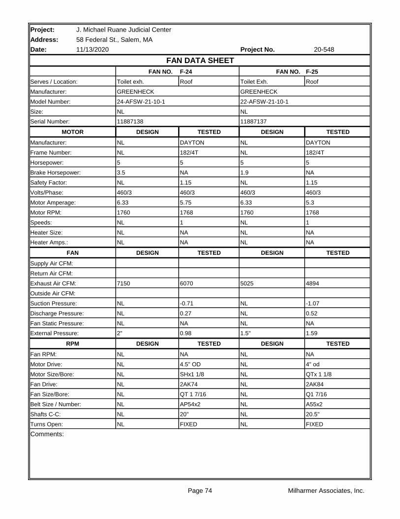
Project: J. Michael Ruane Judicial Center
Address: 58 Federal St., Salem, MA
Date: Project No.
F-24 F-25
Roof Roof
TESTED TESTED
DAYTON DAYTON
182/4T 182/4T
5 5
NA NA
1.15 1.15
460/3 460/3
5.75 5.3
1768 1768
1 1
NA NA
NA NA
TESTED TESTED
6070 4894
-0.71 -1.07
0.27 0.52
NA NA
0.98 1.59
TESTED TESTED
NA NA
4.5" OD 4" od
SHx1 1/8 QTx 1 1/8
2AK74 2AK84
QT 1 7/16 Q1 7/16
AP54x2 A55x2
20" 20.5"
FIXED FIXED
Comments:
Turns Open: NL NL
Belt Size / Number: NL NL
Shafts C-C: NL NL
Fan Drive: NL NL
Fan Size/Bore: NL NL
Motor Drive: NL NL
Motor Size/Bore: NL NL
RPM DESIGN DESIGN
Fan RPM: NL NL
Fan Static Pressure: NL NL
External Pressure: 2" 1.5"
Suction Pressure: NL NL
Discharge Pressure: NL NL
Exhaust Air CFM: 7150 5025
Outside Air CFM:
Supply Air CFM:
Return Air CFM:
Heater Amps.: NL NL
FAN DESIGN DESIGN
Speeds: NL NL
Heater Size: NL NL
Motor Amperage: 6.33 6.33
Motor RPM: 1760 1760
Safety Factor: NL NL
Volts/Phase: 460/3 460/3
Horsepower: 5 5
Brake Horsepower: 3.5 1.9
Manufacturer: NL NL
Frame Number: NL NL
Serial Number: 11887138 11887137
MOTOR DESIGN DESIGN
Size: NL NL
Serves / Location: Toilet exh. Toilet Exh.
Manufacturer: GREENHECK GREENHECK
11/13/2020 20-548
FAN DATA SHEET
FAN NO. FAN NO.
Model Number: 24-AFSW-21-10-1 22-AFSW-21-10-1
Page 74 Milharmer Associates, Inc.

Project:
Address:
Date: Project No.
SYSTEM: F-24 TRAVERSE NUMBER : T1
TRAVERSE LOCATION:
DUCT SIZE (ROUND) " DIAMETER Sq Ft = 0.00
DUCT SIZE (RECT.) 30 " WIDTH x 24 " DEPTH Sq Ft = 5.00
AIR DENSITY DATA
STATIC PRESS @ CL: -0.71 InWg. DESIGN CFM = 7150
DUCT AIR TEMP : 70 Deg F ACTUAL CFM = 6070
BAROMETRIC PRESS : 29.92 In Hg. SCFM= 6063
AIR DENSITY RATIO CORRECTION = 1.00
SCFM CORRECTION FACTOR 1.00
ACTUAL DENSITY 0.075
TEST HOLE 1 2 3 4 5 6 7
A 1297 1455 1517 1548 1568 1567 1664
B 1165 981 1231 1177 1272 1559 1650
C 1246 677 683 851 1219 1512 1542
D 782 793 783 976 1416 1490 1602
E 973 987 925 1248 1501 1498 1356
F
G
H
I
NO. OF READINGS = 40 AVERAGE FPM = 1214
J 939
K 1020
L 1299
M 890
N 700
O
P
Q
R
TECHNICIAN: David Burns
J. Michael Ruane Judicial Center
58 Federal St., Salem, MA
11/13/2020 20-548
TRAVERSE DATA
Page 75 Milharmer Associates, Inc.

Project:
Address:
Date: Project No.
SYSTEM: F-25 TRAVERSE NUMBER : T1
TRAVERSE LOCATION:
DUCT SIZE (ROUND) " DIAMETER Sq Ft = 0.00
DUCT SIZE (RECT.) 24 " WIDTH x 24 " DEPTH Sq Ft = 4.00
AIR DENSITY DATA
STATIC PRESS @ CL: -1.07 InWg. DESIGN CFM = 5025
DUCT AIR TEMP : 70 Deg F ACTUAL CFM = 4894
BAROMETRIC PRESS : 29.92 In Hg. SCFM= 4884
AIR DENSITY RATIO CORRECTION = 1.00
SCFM CORRECTION FACTOR 1.00
ACTUAL DENSITY 0.075
TEST HOLE 1 2 3 4 5 6 7
A 546 1517 1816 1765 1395 1222
B 0 1332 1726 1446 1090 1010
C 0 1517 1777 1720 880 699
D 0 1506 1793 1764 945 1266
E 722 1597 1718 1571 1067 1298
F
G
H
I
NO. OF READINGS = 30 AVERAGE FPM = 1224
J
K
L
M
N
O
P
Q
R
TECHNICIAN: David Burns
J. Michael Ruane Judicial Center
58 Federal St., Salem, MA
11/13/2020 20-548
TRAVERSE DATA
Page 76 Milharmer Associates, Inc.

Project: J. Michael Ruane Judicial Center
Address: 58 Federal St., Salem, MA
Date: Project No.
F-26 F-28
Roof Roof
TESTED TESTED
WEG MARATHON
B56 48Y
3/4 1/4
NA NA
1.35 1.35
460/3 115/1
1.1 3.6
1748 1731
1 1
NA CB
NA CB
TESTED TESTED
1756 239
-0.72 -0.31
0.14 0.04
NA NA
0.86 0.35
TESTED TESTED
INLINE INLINE
VP34 VP34
5/8 1/2
INLINE INLINE
INLINE INLINE
A48 *1
INLINE INLINE
1 4
Comments:
Turns Open: NL NL
*1 Has unibelt, needs new belt.
Belt Size / Number: NL NL
Shafts C-C: NL NL
Fan Drive: NL NL
Fan Size/Bore: NL NL
Motor Drive: NL NL
Motor Size/Bore: NL NL
RPM DESIGN DESIGN
Fan RPM: NL NL
Fan Static Pressure: NL NL
External Pressure: 1" 1"
Suction Pressure: NL NL
Discharge Pressure: NL NL
Exhaust Air CFM: 1475 225
Outside Air CFM:
Supply Air CFM:
Return Air CFM:
Heater Amps.: NL NL
FAN DESIGN DESIGN
Speeds: NL NL
Heater Size: NL NL
Motor Amperage: 1.2 5
Motor RPM: 1740 1725
Safety Factor: NL NL
Volts/Phase: 460/3 115/1
Horsepower: 3/4 1/4
Brake Horsepower: 0.45 0.15
Manufacturer: NL NL
Frame Number: NL NL
Serial Number: 11887614 11887615
MOTOR DESIGN DESIGN
Size: NL NL
Serves / Location: Toilet exh. Toilet Exh.
Manufacturer: GREENHECK GREENHECK
11/13/2020 20-548
FAN DATA SHEET
FAN NO. FAN NO.
Model Number: BSQ-160HP-7 BSC-80-4
Page 77 Milharmer Associates, Inc.

Project:
Address:
Date: Project No.
SYSTEM: F-26 TRAVERSE NUMBER : T1
TRAVERSE LOCATION: Mech 6100
DUCT SIZE (ROUND) " DIAMETER Sq Ft = 0.00
DUCT SIZE (RECT.) 22 " WIDTH x 10 " DEPTH Sq Ft = 1.53
AIR DENSITY DATA
STATIC PRESS @ CL: 0.14 InWg. DESIGN CFM = 1475
DUCT AIR TEMP : 70 Deg F ACTUAL CFM = 1756
BAROMETRIC PRESS : 29.92 In Hg. SCFM= 1758
AIR DENSITY RATIO CORRECTION = 1.00
SCFM CORRECTION FACTOR 1.00
ACTUAL DENSITY 0.075
TEST HOLE 1 2 3 4 5 6 7
A 962 1250 1332 1400 1398 1492
B 988 985 979 983 1069 1353
C 1170 955 895 940 1188 1349
D
E
F
G
H
I
NO. OF READINGS = 18 AVERAGE FPM = 1149
J
K
L
M
N
O
P
Q
R
TECHNICIAN: David Burns
J. Michael Ruane Judicial Center
58 Federal St., Salem, MA
11/13/2020 20-548
TRAVERSE DATA
Page 78 Milharmer Associates, Inc.

Project:
Address:
Date: Project No.
SYSTEM: F-28 TRAVERSE NUMBER : T1
TRAVERSE LOCATION: Mech 2904
DUCT SIZE (ROUND) " DIAMETER Sq Ft = 0.00
DUCT SIZE (RECT.) 12 " WIDTH x 6 " DEPTH Sq Ft = 0.50
AIR DENSITY DATA
STATIC PRESS @ CL: -0.31 InWg. DESIGN CFM = 225
DUCT AIR TEMP : 70 Deg F ACTUAL CFM = 239
BAROMETRIC PRESS : 29.92 In Hg. SCFM= 239
AIR DENSITY RATIO CORRECTION = 1.00
SCFM CORRECTION FACTOR 1.00
ACTUAL DENSITY 0.075
TEST HOLE 1 2 3 4 5 6 7
A 483 378 539
B 421 515 534
C
D
E
F
G
H
I
NO. OF READINGS = 6 AVERAGE FPM = 478
J
K
L
M
N
O
P
Q
R
TECHNICIAN: David Burns
J. Michael Ruane Judicial Center
58 Federal St., Salem, MA
11/13/2020 20-548
TRAVERSE DATA
Page 79 Milharmer Associates, Inc.
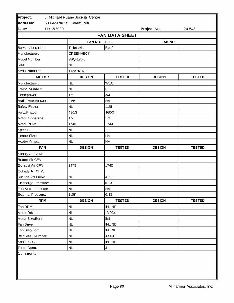
Project: J. Michael Ruane Judicial Center
Address: 58 Federal St., Salem, MA
Date: Project No.
F-29
Roof
TESTED TESTED
WEG
B56
3/4
NA
1.25
460/3
1.2
1744
1
NA
NA
TESTED TESTED
1740
-0.3
0.13
NA
0.43
TESTED TESTED
INLINE
1VP34
5/8
INLINE
INLINE
A41-1
INLINE
3
Comments:
Turns Open: NL
Belt Size / Number: NL
Shafts C-C: NL
Fan Drive: NL
Fan Size/Bore: NL
Motor Drive: NL
Motor Size/Bore: NL
RPM DESIGN DESIGN
Fan RPM: NL
Fan Static Pressure: NL
External Pressure: 1.25"
Suction Pressure: NL
Discharge Pressure: NL
Exhaust Air CFM: 2475
Outside Air CFM:
Supply Air CFM:
Return Air CFM:
Heater Amps.: NL
FAN DESIGN DESIGN
Speeds: NL
Heater Size: NL
Motor Amperage: 1.2
Motor RPM: 1740
Safety Factor: NL
Volts/Phase: 460/3
Horsepower: 1.5
Brake Horsepower: 0.55
Manufacturer: NL
Frame Number: NL
Serial Number: 11887616
MOTOR DESIGN DESIGN
Size: NL
Serves / Location: Toilet exh.
Manufacturer: GREENHECK
11/13/2020 20-548
FAN DATA SHEET
FAN NO. FAN NO.
Model Number: BSQ-130-7
Page 80 Milharmer Associates, Inc.

Project:
Address:
Date: Project No.
SYSTEM: F-29 TRAVERSE NUMBER : T1
TRAVERSE LOCATION: Mech 4600
DUCT SIZE (ROUND) " DIAMETER Sq Ft = 0.00
DUCT SIZE (RECT.) 18 " WIDTH x 14 " DEPTH Sq Ft = 1.75
AIR DENSITY DATA
STATIC PRESS @ CL: -0.3 InWg. DESIGN CFM = 2475
DUCT AIR TEMP : 70 Deg F ACTUAL CFM = 1740
BAROMETRIC PRESS : 29.92 In Hg. SCFM= 1740
AIR DENSITY RATIO CORRECTION = 1.00
SCFM CORRECTION FACTOR 1.00
ACTUAL DENSITY 0.075
TEST HOLE 1 2 3 4 5 6 7
A 1147 1153 858 1215 1081
B 783 1443 1441 1548 1352
C 562 681 1125 1173 770
D 403 631 961 945 615
E
F
G
H
I
NO. OF READINGS = 20 AVERAGE FPM = 994
J
K
L
M
N
O
P
Q
R
TECHNICIAN: David Burns
J. Michael Ruane Judicial Center
58 Federal St., Salem, MA
11/13/2020 20-548
TRAVERSE DATA
Page 81 Milharmer Associates, Inc.


![[O] cOmpaniessavarinocompanies.com/content/documents/bids... · hvac general notes hvac abbreviations hvac ductwork symbols hvac control symbols chaintreuil jensen stark architectural](https://img.pdfslide.us/doc/110x75/5ae5a13f7f8b9a29048c7dfa/o-compan-general-notes-hvac-abbreviations-hvac-ductwork-symbols-hvac-control-symbols.jpg)