Embed Size (px)
Citation preview
0lD-AISS 627 A COMPUTER-INTERACTIVE SINGLE SPECIMEN J-INTEGRRL L.'1FRRCTUAtE TOUGHNESS TEST(U) MATERIALS RESEARCH LABSASCOT YALE (AUSTRRLIR) D S SAUNDERS ET AL. SEP S6
I5CLSSIFIE BL-R-1S IF/0 2/5NL
EmhmhmhhmhhmhI
- &1& Q2.0-L=I- tau
E.
FILE COPY-
DEPARTMENT OF DEFENCEDEFENCE SCIENCE AND TECHNOLOGY ORGANISATION
MATERIALS RESEARCH LABORATORIESNI0 MELBOURNE, VICTORIA
REPORT
t M:L-R-1021
A COMPUTER-INTERACTIVE, SINGLE SPECIMEN J-INTEGRALFRACTURE TOUGHNESS TEST
D.S. Saunders and I.A. Burch
DTIC
S-<DApproved for Public Release&/
CoQmnwelth of AustraliaIo"PTEMBER,.1986
87 9 25 053
* -0 <
DEPARTMENT OF DEFENCE
MATERIALS RESEARCH LABORATORIES
REPORT
N ~R-R-1021
A COMPUTER-INTERACTIVE, SINGLE SPECIMEN J-INTEGRAL
FRACTURE TOUGHNESS TEST
D.S. Saundersrand I.A. Burch
ABSTRACT
This report outlines the development of a computer-interactive,single specimen J-integral fracture toughness test method. The test methodwas developed on a PDP 11/04 computer and MTS 810 servo-hydraulic test machineusing compact tension specimens machined from a NiMoCr gun steel. The reportdiscusses some of the theoretical concepts of the J-integral, particularlythose which are relevant to the test method which involves the measurement ofarea under the load/load-line-displacement curve and the measurement of crackextension. The report also discusses in detail some of the errors within thecomputer-interactive, single specimen J-integral test method and how these canbe reduced. It is concluded that the test method permits the evaluation ofthe J-integral fracture toughness of high strength steels In accordance withthe existing (ASTM) standard.
*Acce-_'on Fr{
K T IS CRA&I W
QUALTY C' C. TAB 0]1a"SPECTEDo.:=ed 0 0
By
.4 Di~t ib,. t; I..... L...........
Approved for Public Release i
POSTAL ADDRESS: Director. Materials Research LaboratoriesP.O. Box 50. Ascot Vale, Victoria 3032. Australia
sscURZTY cLASSzVICATON or Thzu PA0G UNCLASSIFIED
DOCUMENT CONTROL DATA S33T
333ORT go. AR NO. 3310RT SECURZTY CLASSIFICATION
MRL-R-1021 AR-004-838 Unclassified
TITZE
A computer-ilnteractlve, single specimen J-Integralfracture toughness test
AUTSOR (S) CORPORATs AUTHOR
Materials Research LaboratoriesD.S. Saunders P.O. Box 50,I.A. Burch Ascot Vale, Victoria 3032
33o3 DAT3 TASK NO. 1SPOSOR
September 1986 ARM 84/155 Army
-ILE NO. R3RERCRS PAGUS
G6/4/8-3203 35 , 62
CLASSZFICATION/ 1ZHITATION REVIZW DATE CLASSZFXCATXON/RELZAS3 AUTHORITY
Superintendent, MRLMetallurgy Division
SECONDARY DISTRIBUTION
-s, Approved for Public Release
ANEOUNCXEZNT
Announcement of this report is unlimited
EITWORDI
J-Integral Fracture Toughness Gun BarrelSingle Specimen Test Computer Interactive Steel
COSATI GROUPS 09020
ARST2ACT
This report outlines the development of a computer-interactive,
single specimen J-integral fracture toughness test method. The test methodwas developed on a PDP 11/04 computer and MTS 810 servo-hydraulic test machineusing compact tension specimens machined from a NiMoCr gun steel. The reportdiscusses some of the theoretical concepts of the J-integral, particularlythose which are relevant to the test method which involves the measurement ofarea under the load/load-line-displacement curve and the measurement of crackextension. The report also discusses in detail some of the errors within thecomputer-interactive, single specimen J-integral test method and how these canbe reduced. It is concluded that the test method permits the evaluation ofthe J-integral fracture toughness of high strength steels in accordance withthe existing (ASTM) standard.
SECURITY CLASSIFICATION or THIS PAGE
UNCLASSIFIED
111.r 1 1 1 .1 1 1
CONTENTS
Page No.
1. INTRODUCTION
2. THE J-INTEGRAL 2
3. OBJECTIVES OF THE DEVELOPMENT OF THE COMPUTER-INTERACTIVETEST METHODS
4. J-INTEGRAL TEST SPECIMENS 7
5. COMPLIANCE CALIBRATION FOR THE S-INTEGRAL SPECIMENS 8
6. HARDWARE FOR THE COMPUTER-INTERACTIVE SINGLE SPECIMEN Jc TEST 9
7. SOFTWARE FOR THE COMPUTER-INTERACTIVE SINGLE SPECIMENJ-INTEGRAL TEST 9
" 7.1 The control program on the PDP11/04-MTS 810 10
7.2 The data analysis programs on the VAXII/780 and PDPI1/04 12
8. COMPUTER-INTERACTIVE, SINGLE SPECIMEN J-INTEGRAL TESTS AND AMULTIPLE SPECIMEN J-INTEGRAL TEST ON A Ni-Cr-Mo GUN STEEL 13
9. FURTHER APPLICATION OF THE COMPUTER-INTERACTIVE, SINGLESPECIMEN J-INTEGRAL TEST METHOD 21
10. DISCUSSION 21
11. CONCLUSIONS 27
12. ACKNOWLEDGEMENTS 27
13. REFERENCES 28
A'
LIST OF SYMBOLS
a - crack length
'- initial crack length
a - final crack length
Aa - af - aO - crack extension
A - area under load/load-line-displacement record
b - uncracked ligament length
B - specimen thickness
CTOD - crack tip opening displacement
E - Young's modulus
- 2
Err% - error in measurements
E(e,n) - non-dimensional function of * and n
I- coefficient of strain hardening stress intensity
J - J-integral value
- critical value of J
- critical value of J measured in Mode I opening
K - stress intensity factor
KIc - critical value of K measured in Mode I opening and bydefinition is used as a measure of plane strain fracturetoughness
KQ - critical value of K measured under conditions which cannot bedemonstrated to meet all criteria for a valid Kic test.
L - half-span of a beam in three point bending
M - bending moment
n - work hardening exponent in the Ramberg-Osgood power hardening law
p - used to denote load-control
P - force
r - distance ahead of a crack tip in r,9 polar co-ordinate system
ds - increment in the contour path

T - the outward fraction vector on ds.
u - the displacement vector at ds
U - potential energy of a cracked body under load
X - used to denote displacement control
V - load-line-disp;acement
W - loading work per unit volume
- constant In Ramberg-Osgood power hardening law
r - the path of the integral wnich encloses the crack tip
- strain
Cy - yield strain
e i - strain tensor
Sel + *pl W total angular deflection of a beam
I el - elastic contribution to total angular deflection
0 - plastic contribution to total angular deflectionpl
S- angular displacement ahead of a crack tip in r,s polar co-ordinate system
- a parameter of value x 1 for metals
S- Poisson's ratio
o stress
;y - yield stress
00.2 - 0.2% proof stress
*UTS - ultimate tensile stress
00.2 + UTSaeff a 2 - an effective yield stress
- stress tensor
r(o,n) - non-dimensional function of s and n
A COMPUTER-INTERACTIVE, SINGLE SPECIMEN
J-INTEGRAL FRACTURE TOUGHNESS TEST
1. INTRODUCTION
In the fields of engineering and materials science the concept oflinear-elastic facture mechanics is an accepted part of material testing. Theuse of plane strain fracture toughness as a material property is useful inengineering studies because it allows the prediction of critical crack sizeswhere the stresses in a body or structure are known. The measurement of planestrain fracture toughness, Kic, is covered by ASTM Standard E 399 (1]. Thistest is relatively simple and, for the most part, easily.understood. For
.A plane strain fracture toughness to be measured in any test a most importantcriterion which must be met is that the specimen size be sufficiently large to
9 ensure that plane strain conditions prevail across most of the specimenthickness. This means that there Is a minimum specimen size for each materialtested. Thus the specimen thickness and the crack length must both be
ga t2 where KIc is the measured plane strain fracturetoughness and 002 is the 0.2% proof stress of the material.
In many instances materials are tested from parent bodies which do
not allow specimens large enough for the measurement of KIc to be taken fromthem. For example, some modern, large calibre gun barrels are ofsufficiently high toughness that valid plane strain fracture toughnessspecimens cannot be taken from the walls of the gun tube. Tests using sub-sized specimens exhibit unacceptably high plasticity in their test records andhence alternative test techniques to the KIc test method must be used. Onemethod which admits a degree of plasticity is the J-integral test method whichis covered by ASTM Standard E 813 (2]. The test method predicts a criticalvalue of J at which the crack first begins to extend. By convention thiscritical value of J is denoted JIc because the test is predominantly in mode Iopening.
Under most circumstances the measurement of JIc for a high toughnessmaterial (such as gun barrel steel) is an involved, multiple specimen testmethod because the critical value of J has to be inferred fromthe J-Aa behaviour obtained from a number of specimens. Aa is the increase
1
.4
in crack length associated with each J measurement, and will be discussed inthe following section. However, now that computer-interactive test machinesare readily available to researchers it is possible to make use of the singlespecimen J-Integral test method which utilizes unloading compliancemeasurements from which the extent of crack growth is inferred.
A short paper covering the initial development of the computer-interactive single specimen J-integral test method at MRL has been published(31. The present work covers the same general aspects of the test method as(31 but expands considerably on details of computer programs and erroranalyses. This is facilitated by practical examples of the J-integral testusing a gun barrel steel.
2. THE J-INTEGRALAf
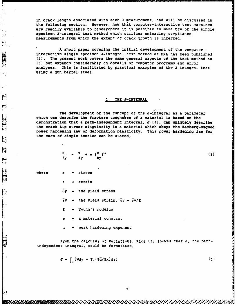
The development of the concept of the J-integral as a parameterwhich can describe the fracture toughness of a material is based on thedemonstration that a path-independent Integral, J (41, can uniquely describethe crack tip stress singularity in a material which obeys the Ramberg-Osgoodpower hardening law of deformation plasticity. This power hardening law forthe case of simple tension can be stated,
L. +. {._}n (1)- + a6I)
y ;y oy
where a - stress
c- strain
oy - the yield stress
ey - the yield strain, ey - ay/E
E - Young's modulus
a - a material constant
n - work hardening exponent
From the calculus of variations, Rice (5) showed that J, the path-independent integral, could be formulated,
J - Jf(Wdy - T.(3u/ax)ds) (2)
2
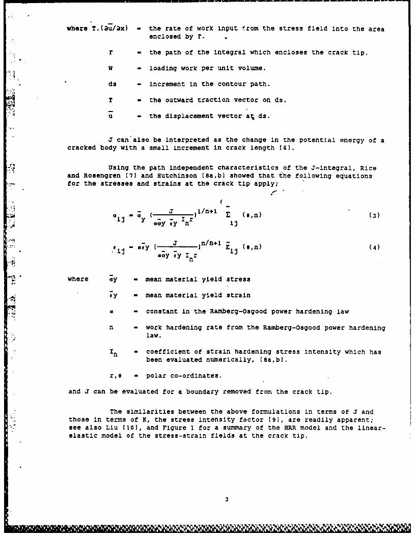
where T.(au/ax) - the rate of work input from the stress field into the area
enclosed by r.
r - the path of the integral which encloses the crack tip.
W - loading work per unit volume.
ds - increment in the contour path.
T - the outward traction vector on ds.
u - the displacement vector at, ds.
J can also be interpreted as the change in the potential energy of acracked body with a small increment in crack length [6].
Using the path independent characteristics of the J-integral, Riceand Rosengren [71 and Hutchinson [8a,b] showed that the following equationsfor the stresses and strains at the crack tip apply;
aij I o y[r J/n+1 E (9,n) (3)y,. Goy 7y n ij
a,.y J- ]n/n+1..- a cy y I n/ En i (9,n) (4).i";• j aoy eylIr
n
where ;y - mean material yield stress
7y - mean material yield strain
a - constant in the Ramberg-Osgood power hardening law
n - work hardening rate from the Ramberg-Osgood power hardeninglaw.
in - coefficient of strain hardening stress intensity which hasbeen evaluated numerically, [Sa,b].
r,e - polar co-ordinates.
and J can be evaluated for a boundary removed from the crack tip.
The similarities between the above formulations in terms of J andthose in terms of K, the stress intensity factor [9], are readily apparent;see also Liu (10], and Figure 1 for a summary of the HRR model and the linear-elastic model of the stress-strain fields at the crack tip.
3
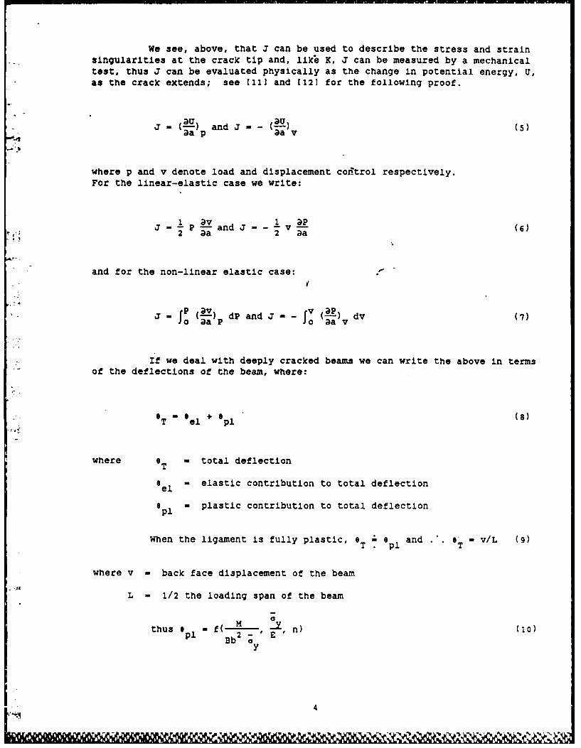
We see, above, that J can be used to describe the stress and strainsngularities at the crack tip and, likle K, J can be measured by a mechanicaltest, thus J can be evaluated physically as the change in potential energy, U,as the crack extends; see [111 and [12] for the following proof.
j (-U ndJ._-(u)
aa p aav
where p and v denote load and displacement control respectively.For the linear-elastic case we write:
J - 1 P av and J -- v - (6)2 aa 2 .a
and for the non-linear elastic case:
? (2V) dP and J v (2vP) dv (7)J aa P 0 aav
If we deal with deeply cracked beams we can write the above in termsof the deflections of the beam, where:
0 T el + ep1 (8)
where T - total deflection
el ' elastic contribution to total deflection
o - plastic contribution to total deflectionel
When the ligament is fully plastic, 6 0 l and e 6' v/L (9)
T. p1 T
where v = back face displacement of the beam
L - 1/2 the loading span of the beam0
thuso - f( M , -** n) (10)Bb 2 ;Ey
4
2 Y el- Bb'h($ E n) 11)
and M - PL
thus P a h ( - n) (12)SLE
we knw IP 3 2bB-wenwaa Tb L - y L hn (13)
and substituting L - in (13) and (7)
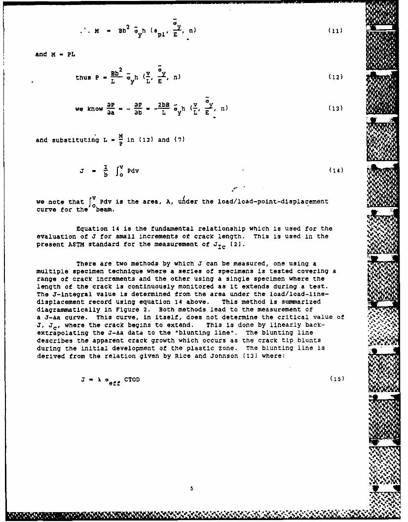
J jo Pdv (14)
'Vwe note that Pdv is the area, A, under the load/load-point-displacementcurve for the Jbeam.
Equation 14 is the fundamental relationship which is used for theevaluation of J for small increments of crack length. This is used in thepresent ASTM standard for the measurement of JIc (2].
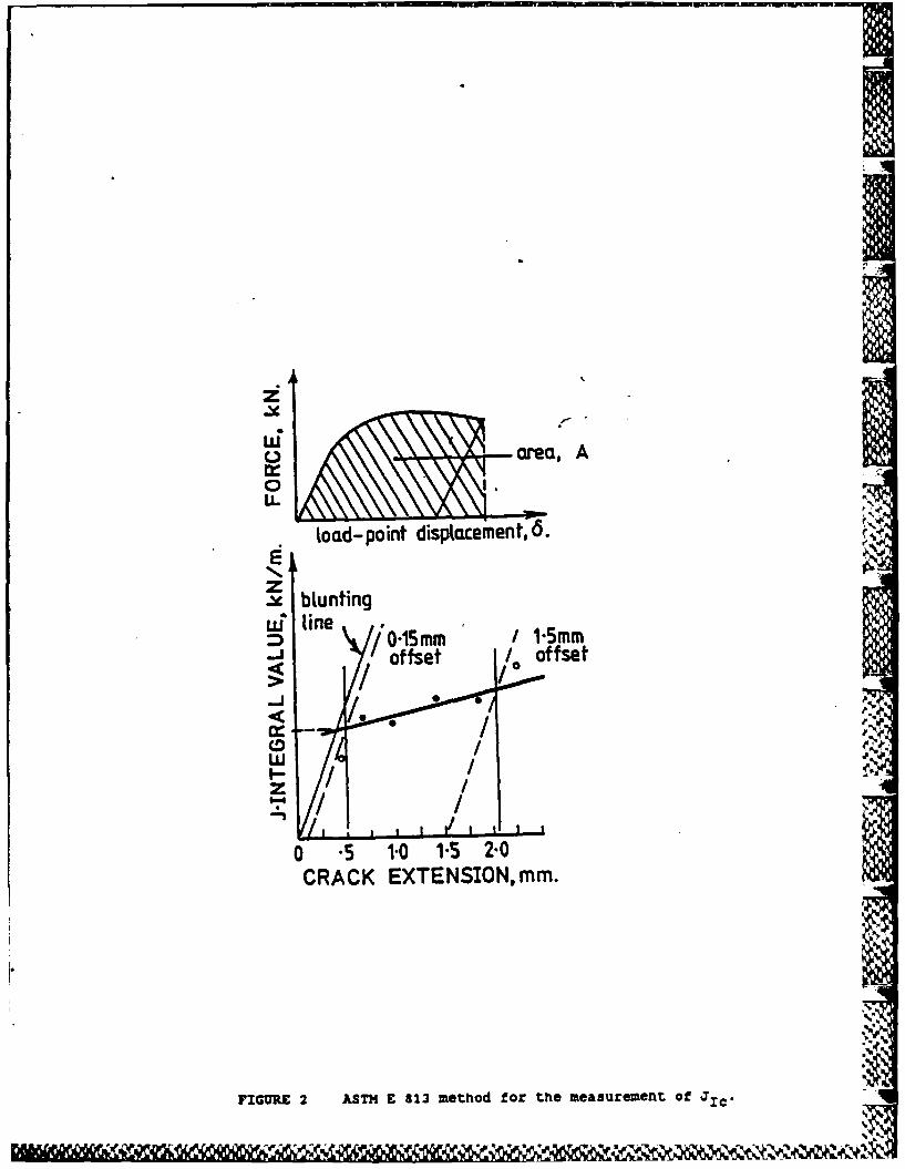
There are two methods by which J can be measured, one using amultiple specimen technique where a series of specimens is tested covering arange of crack increments and the other using a single specimen where thelength of the crack is continuously monitored as it extends during a test.The J-integral value is determined from the area under the load/load-line-displacement record using equation 14 above. This method is summarizeddiagrammatically in Figure 2. Both methods lead to the measurement ofa J-Aa curve. This curve, in itself, does not determine the critical value ofJ' ac' where the crack begins to extend. This is done by linearly back-extrapolating the J-Aa data to the "blunting line". The blunting linedescribes the apparent crack growth which occurs as the crack tip bluntsduring the initial development of the plastic zone. The blunting line isderived from the relation given by Rice and Johnson [13] where:
J -X ef f CTOD (i5)kf
A7 h
where I 1 for metals
a eff - effective yield strength of the material
CTOD - crack tip opening displacement.
-* The effective increment in the position of the crack tip, &a, can beconsidered to be about 0.5 x CTOD and hence a simple relation for this
qi blunting line can be written
J - 2 X aeff x Aa (16)
00.2 + UTS)*where a is often defined as ( +
eff 2
The point where the linear regression line through alladmissible J-Aa data pairs [2] intersects the blunting line is considered tobe the critical value of J at which the crack first extends.
What constitutes admissible J-Aa pairs is discussed in detail in(2].
The computer-interactive, single specimen J-integral test methoddescribed in the following sections permits the measurement of JIc inaccordance with the ASTM standard 121.
3. THE OBJECTIVES OF THE DEVELOPMENT OF THE COMPUTER-INTERACTIVE,
SINGLE SPECIMEN J-INTEGRAL TEST METHOD
When all refinements are completed, (and this can only be achievedby the continued use of the test method developed here), the test methodshould permit the determination of JIc' i.e. fracture toughness, on a routinebasis and in accordance with ASTM E 813 [2].
The objectives of the development of the computer-interactive singlespecimen J-integral test method are:
The ASTM Standard, (2), suggests that "when estimating aeff influences
of testing conditions such as loading rate and temperature should beconsidered".
6I
(1) Accurately determine JIc,
(2) Document all relevant calculations,
(3) Store all test data in a logical and retrievable form,
(4) Be flexible in a mathematical sense to allow compliancecalibrations, Young's modulus, Merkle-Corten coefficient and othertest parameters to be inserted into the program or readily changed,
(5) Ability to re-examine test data.
Due to the limited transient programming area (TPA) of 32 K wordsavailable in the PDP11/04 computer at the time of the development of theprogram for the control of the J-integral test, the program may be regarded asincomplete because it does not undertake the linear regression throughthe J-A a test data to the blunting line for the calculation of JIc" This canbe done using a plotting file created for this purpose.*
The objectives ()-(4) are met by the cqrrent J-test program for thePDP11/04; JCTS.BAS, for the compact ension specimens. Objective 5 is met byprograms written for both the VAX11/780 and the PDP11/04 which allow fileswritten by the PDP11/04 under RT11 version 4.1 to be treated as data files forwhat is effectively another J-integral test. This program, JRERUN.BAS, re-examines the existing data but allows the insertion of accurate specimendimensions and crack lengths and the use of alternative compliancecalibrations in the calculations. Estimates of the accuracy of the linearregression analysis to infer crack-length are made by this program.
The programs are listed in Appendix 1 and details of these programs- are given later in this report.
4. THE J-INTEGRAL TEST SPECIMENS
The present work was mainly undertaken for the "compact tension"specimen design and although the test method is readily applicable to beamspecimens, it is not dealt with in detail in this report.
.24
This feature will be incorporated in the program when the computer is
upgraded to a PDP11/34 which has a larger TPA.
.7
- *I? III
Several specimen designs have been proposed for the compact tensionspecimen for J-integral testing 141. The primary requirement from thespecimen is the need for the measurement of the load-line-displacement, seeequation 14 above.
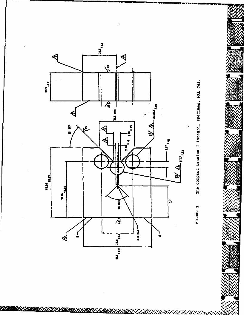
For J-Integral testing the present work used a modified compacttension specimen which conforms to the ASTM E 399 specimen geometry exceptthat it has an integral knife edge machined at the load-line, see Figure 3.This specimen is similar to that proposed by Clarke et al (141, except thatthe pin holes are closer together. The advantage of utilizing specimens whichare essentially common to the E 399 and E 813 test methods is that, where KIccannot be measured, the specimens are readily converted to J-Integralspecimens. The MRL specimen design would probably preclude the use ofClevises with roller bearings, however, there is no conclusive evidence thatthis is a necessary feature of J-integral tests using the compact tensionspecimen.
The J-integral specimen manufactured by MRL*is designated MRL J03,[151.*
5. THE COMPLIANCE CALIBRATION FOR THE COMPACT TENSION J-INTEGRAL SPECIMENS
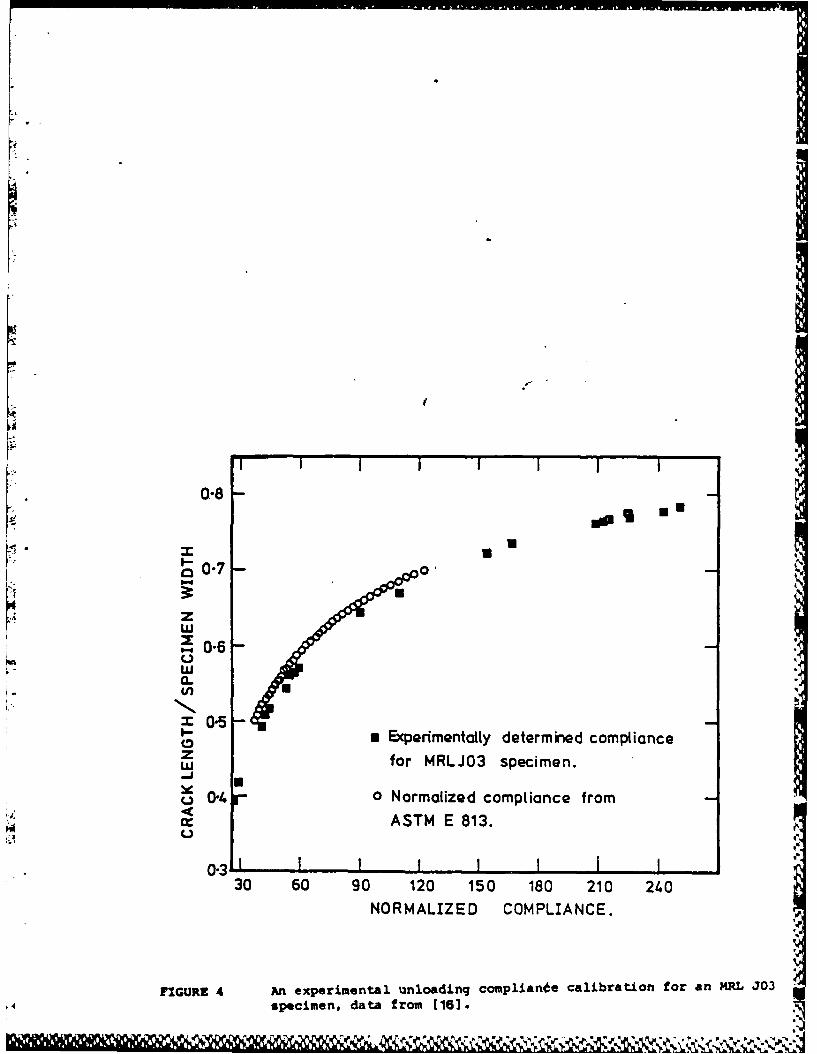
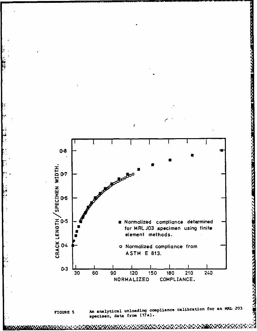
At the present time there are two elastic unloading compliancecalibrations which are immediately applicable to the MRL J03 specimen. Thefirst is an experimental unloading calibration using 13 mm thick MRL J03specimens (16], and the second a theoretical compliance calibration developedfrom a finite element program, PAFEC, run on a VAX 11/780 computer C17a,b].These compliance calibrations are plotted in Figures 4 and 5 together with theunloading compliance calibrations supplied in ASTM E 813 (see also Saxena andHudak I18) and Newman (191). These calibrations are used in Section 8 of thiswork. Listings of the compliance data for compact tension specimen designsare given in Appendix 2.
This is a specific designation. The "03" refers to an a/W of 0.3. Other
starter crack lengths can be used.
8U
VV V
6. THE HARDWARE FOR THE COMPUTER-INTERACTIVE
SINGLE SPECIMEN JIc TEST
The single specimen J-integral tests were undertaken on a 250 kNservohydraulic testing machine (MTS 810 system), interactive with a PDP11/04computer.*
The graph generated by the program, J-Aa, was plotted on a Tektronix4010-1 VDU and dumped via a Tektronix thermal imager while the analogue outputof load/load-line-displacement was plotted using a HP 7090A plotter. Thisplotter can be controlled by the PDP11 and hence could be used for the re-plotting of the.data as stored by the program. More conveniently this ishandled via the VAX11/780 and appropriate graphics terminals.
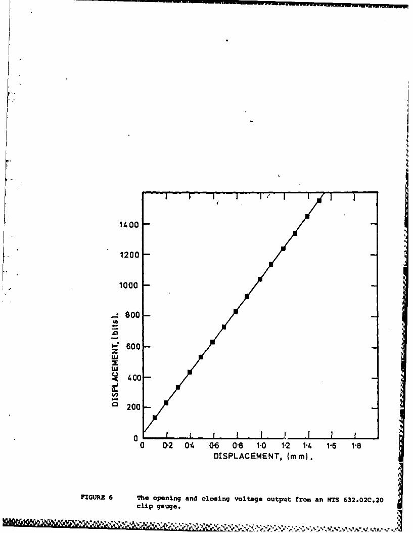
The load-line-displacement was measured using an MTS 632.02C.20 clipgauge. The locating edges on the clip gauge arms were modified slightly toaccommodate the MRL J03 integral knife edge design. The linearity andreproducibility of this clip gauge were tested experimentally and the dataplotted In Figure 6. It was considered unnecessary-to use any correctionfactors over the range used for the J-ntegral test of an MRL J03 specimen.
7. THE SOFTWARE FOR THE COMPUTER-INTERACTIVE
SINGLE SPECIMEN J-INTEGRAL TEST
K *The software written for the single specimen J-integral test methodand the data analysis programs are largely interactive and self explanatory,however brief descriptions of the programs are given in Appendix 3. Somedocumentation of the variables in the control program for the PDP 11/04, whererelevant to the description of the software in this section, is given inAppendix 4.
The programs which undertake J-integral testing and data analysis
are in two separate suites.
(1) The computer-interactive control program written for the PDP 11/04.
and
(2) The data analysis programs written for the VAX11/780 and PDP11/04which utilize the data generated and stored on disc by the controlprogram.
This computer has a TPA of 32K words but is to be upgraded to a PDP11/34with a TPA of 64K words.
9
i*J
7.1 The control progranm on the PDP1l/04-MTS 810
The language used for the control program is DEC Multi-user BASICwith MTS and Tektronix enhancements for the Master Segment Generator and thegraphics respectively [20a,bI. The Master Segment Generator (MSG) is used togenerate, through a D/A converter, the offset signal to drive the servo-valve.
The single specimen J-integral test is conducted in stroke control,with the position of the ram being measured by its displacement transducerrather than using the displacement of the specimen as measured by the clipgauge. This makes the test fall safe should the clip gauge signal fail.
At the present time, for J-integral tests using the MRL J03specimens, ± 2047 bits - ± 5 mm of rar travel. This stroke can be decreasedto allow an increase in the number of data points acquired for any test usingJ03 specimens. Incrementing the stroke during the test results in a smallincrement in the load applied to the specimen, while displacement in the load-line of the notch Is measured by the clip gauge where ± 2047 bits -±2 mm.For the MRL J03 specimen it is found that 2 mm movement of the clip gauge isample for most J-integral tests. This calibration can be altered using theMTS 440.21 signal conditioner to increase the sensitivity of the test,
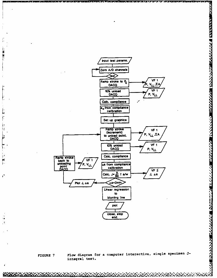
The software for the test method is summarised in the flow diagram,Figure 7.
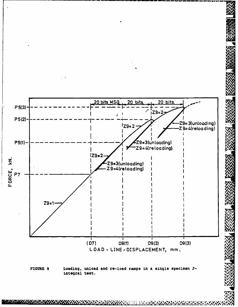
The single specimen J-integral test method requires the collectionof load/load-line-displacement data for each bit-wise increment (or decrementin the case of an unloading) produced by the Master Segment Generator,(MSG). Each bit-wise increment and decrement in stroke is accompanied by thesequential reading number and with each'reading is recorded load, load-line-displacement, cumulative area under the load/displacement record and aswitching integer (zg), which has a value of 1,2,3, or 4 depending on the callto the MSG, i.e. the ramp control. These data are written sequentially into alarge virtual file on disc as binary numbers. The switch, Z9, is the integerused to control the loading and the unloading sequences of the test and Isincorporated in an "ON GOTO" statement to call the bit-wise output from theMSG, see Figure 7. The ramp control Is shown schematically in Figure 8. Theswitch has an important secondary function in the JRERUN.BAS programs on theVAX11/780 and PDP 11/04 where this record is used to control the use of theload/load-line-displacement data in a manner analogous to the control programon the PDP11/04, viz., the switch designates data which are to be treated asunloading data for inferring crack length via the unloading compliance and thenormalized compliance/normalized cracklength calibration such as those inFigures 3 and 4. JRERUN.BAS is discussed in detail in section 7.2.
The acquisition of the load/load-line-displacement data isundertaken as a separate (but common) subroutine (through a "GOSUB" statement)called by each of the ramp routines set by the ramp switch, i.e. theacquisition of data is always undertaken in the same manner. Thus, for eachsequential bit-wise increment or decrement in stroke from the MSG, when theram of the MTS has stopped moving, ten reading pairs of load and load-line-displacement are taken at 1 millisecond intervals and then averaged. These
10
average values are "written* Into the record and used for the calculation ofthe cumulative area under the load/displacement curve. Once all calculationshave been completed the ramp is re-activated, see Figure 8.
Initially the test behaves in a linear-elastic manner. A load, P7,to which the specimen can be loaded and still remain linear-elastic is used toestablish that the area calculation is correct. This is done by comparing thecumulative area up to this elastic load with a geometric calculation using theslope of the linear-elastic loading line and the elastic load; viz. the areaof a triangle. In the linear-elastic region the cumulative area should be towithin +2% of the geometric calculation.
The test parameters such as specimen dimensions, Young's modulus,elastic load for preliminary calculations, Merkle-Corten coefficients [21] andthe load cell calibration are inserted into the computer and also stored inthe data file ("name".DAT) at the start of the test. A plotting file("name".PLT) is also set-up concurrently with the data file. The graphics forthe J-Aa plot are also set-up before the test. The test starts with aninitial loading in the linear-elastic range, the limit set by the elastic load(z9-I), and the area calculation is checked as described above. After a 20bit increment In stroke when Z9-2 (seq next paragraph), a 10% unloading (Z9-3)allows the initial crack length (ao) to be established from the unloadingcompliance calibration in the program.* To produce crack growth in acontrolled way the bit-wise increment in stroke (Z9-2) is limited to a pre-setnumber of bits from the MSG. This can be changed readily within the programbut for a compact tension specimen geometry such as the MRL J03 It has beenfound that 20 bits total output from the MSG for each loading ramp issufficient to produce measurable crack extension. As the stroke is increasedthe cumulative area under the load/displacement curve is "written" into thedata and plotting files (vF1 and VF2 respectively). On attaining the totalnumber of bits of stroke increment the specimen is unloaded (Z9-3) to 90% ofthe load in the preceding loading ramp and, using a linear regression analysison the data, the unloading compliance is calculated and normalized withrespect to E (Young's modulus) and B (specimen thickness). No area under thecurve is calculated In this section of the program. Through the compliancecalibration in the program (see Section 5), crack length is inferred and thecorresponding J-integral value calculated using equation 14. A summary ofthese results is "written" into the plotting file (VF2). The J-integral testthen continues, firstly by restoring the specimen to the displacement at thetop of the unloading (Z9-4) and then by bit-wise Incrementing the stroke afurther 20 bits (Z9-2) to promote further crack growth. The determination ofthe area under the load/displacement curve is resumed at the point in theprogram when Z9-2.
It has been found that a is often better estimated if this first 10%unload is used for the calculation rather than the initial elastic loadingas specified in [21. This unloading must occur in the linear-elasticregime.
The data "written" into the virtual files (VFI and VF2) can beretrieved using the program ACCESS.BAS. ° All details of the test includingscaling factors are included In the printout of data from the PDP11/04 virtualfiles.
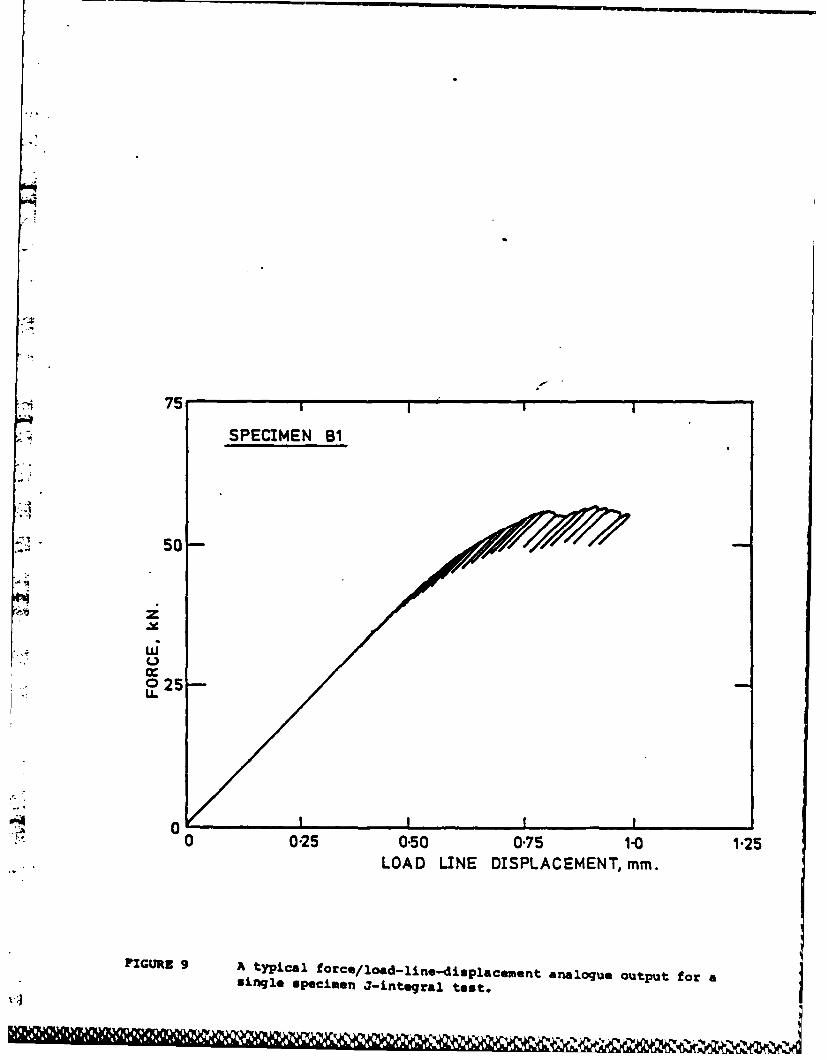
A typical analogue output from a single specimen J-Integral test isgiven in Figure 9; this will be dealt with in detail in Section 8 when thetest results from gun steel are discussed.
7.2 The data analysis programs on the ViXiIi/70 and PDP11/04
The main program in this suite of programs for the VAX11/780 andPDP11/04 is for the re-analysis of the test data for the purpose of arithmeticchecks and the use of alternative calibrations or test details such asspecimen dimensions etc. To use this program on the VAX the data file used by
Athe JRERUN.BAS program must be in ASCII code. The data file created on thePDP11/04 and loaded Into the VAX11/780 is in binary numbers and must thereforebe re-written in ASCII code. This is achieved by a small program to create anASCII code output file which can be utilised by the data anlaysis programs(see Appendix 2 for details). In the ease of JRERUN.BAS for the PDP 11/04 thevirtual files are read directly. In all other respects the programs aresimilar.
The data analysis program, JRERUN.BAS requires specimen details tobe input again (should errors be discovered in the original measurement of thespecimen) and also, with the accurate measurement of initial crack length nowthat the test specimen has been broken open after heat tinting, a correctvalue of the Merkle-Corten coefficient can be inserted for compact tension Jtests. Similarly Young's modulus can be changed for the re-analysis of thetest data. Most importantly, however, alternative compliance calibrations canbe used if they are available for the specimen geometry tested. This should
*: allow the eventual attainment of better correspondence between measured cracklength values and those inferred by the unloading compliance technique. Thestandard, ASTM E 813 (21, requires "that the final crack extension value, aspredicted by single-specimen techniques, must agree with the averaged heat
., tint values within 15%". Using the present re-analysis method thisrequirement can usually be met for the compact tension J-integral specimen(see Section 9). The JRERUN.BAS program also gives the correlationcoefficients for linear regression analysis of the unloading data and alsopermits the examination of the load/load-line-displacement data pairs todecide if any should be discarded from the start of the unloading to allow fornon-linear effects. Some computer-interactive J-Integral test programs use adelay before an unloading to reduce non-linear effects and time-dependent,plastic recovery (22,233. The control program on the PDP11/04 overcomes non-linear effects to some extent by discarding a fixed number of data points forthe linear regression to establish the compliance. The data analysis programon the other hand allows the number of points which are discarded to be variedat each unloading.
12
11
The program prints a summary of all calculations together with alltest details including the compliance cAlibration used to infer the crackextension in the J-integral test.
Another program, ACCESS1.BAS, for the VAX only, is a simple utilityto allow the examination of any part of the load/load-line-displacement record"(stored as load/load-line-displacement data pairs). This program "writes" asimple plotting file which can be used with MRL utility program GRAPH (241 sothat the record between any two reading numbers can be replotted. TheACCESS1.BAS/GRAPH combination can be used to examine for any hysteresis In theunloading/reloading sequence and to obtain the slope of any unloading orreloading part of the record, should this be necessary (see Section lo).
S. COMPUTER-INTERACTIVE, SINGLE SPECIMEN J-INTEGRAL TESTS AND
A MULTIPLE SPECIMEN J-INTEGRAL TEST ON A Ni-Cr-MO GUN STEEL
The material used in this wqrk was taken as MRL J03 compact tensionspecimens in the transverse orientation from a 4.5 inch Naval gun.* Thismaterial was used for the preliminary investigation of the J-integral testmethod (31 because limited fracture toughness data was avallable for thissteel (25,26]. The chemical composition of the steel Is given in Table 1.
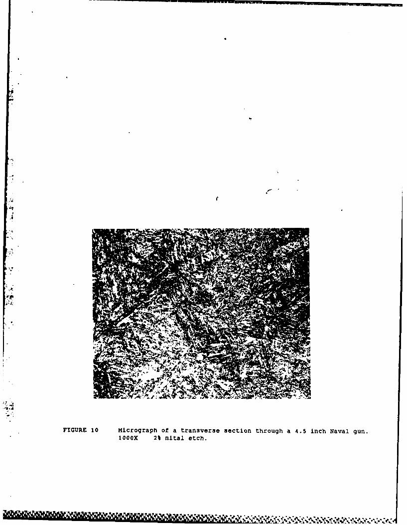
A micrograph of the steel, with orientation transverse to the barrelwall, is shown in Figure 10.
The mechanical properties of this gun steel have been reported inearlier work (251 and are summarised in Table 2. Estimates of fracturetoughness, using ASTM E 399 [1], were made from the load/displacement recordsof tests on the steel (261; these are reproduced in reference 25. It shouldbe noted, however, that the fracture toughness values reported in Table 2 aredesignated as K values because the fracture toughness tests were invalid(261. For the 51 mm thick compact 'C'-shaped specimens (51CC) and the 51 mmthick compact tension specimens (51CT) the Pmax/P5 ratios were approximately1.12. It is considered, therefore, that the K0 values reported in Table 2approach the Kic of the 1aterial. Thus in the transverse orientation Kic isapproximately 130 MN m-'2 .
* MRL Reference, Barrel G1 (1971).
13
,p. . *.. .*-
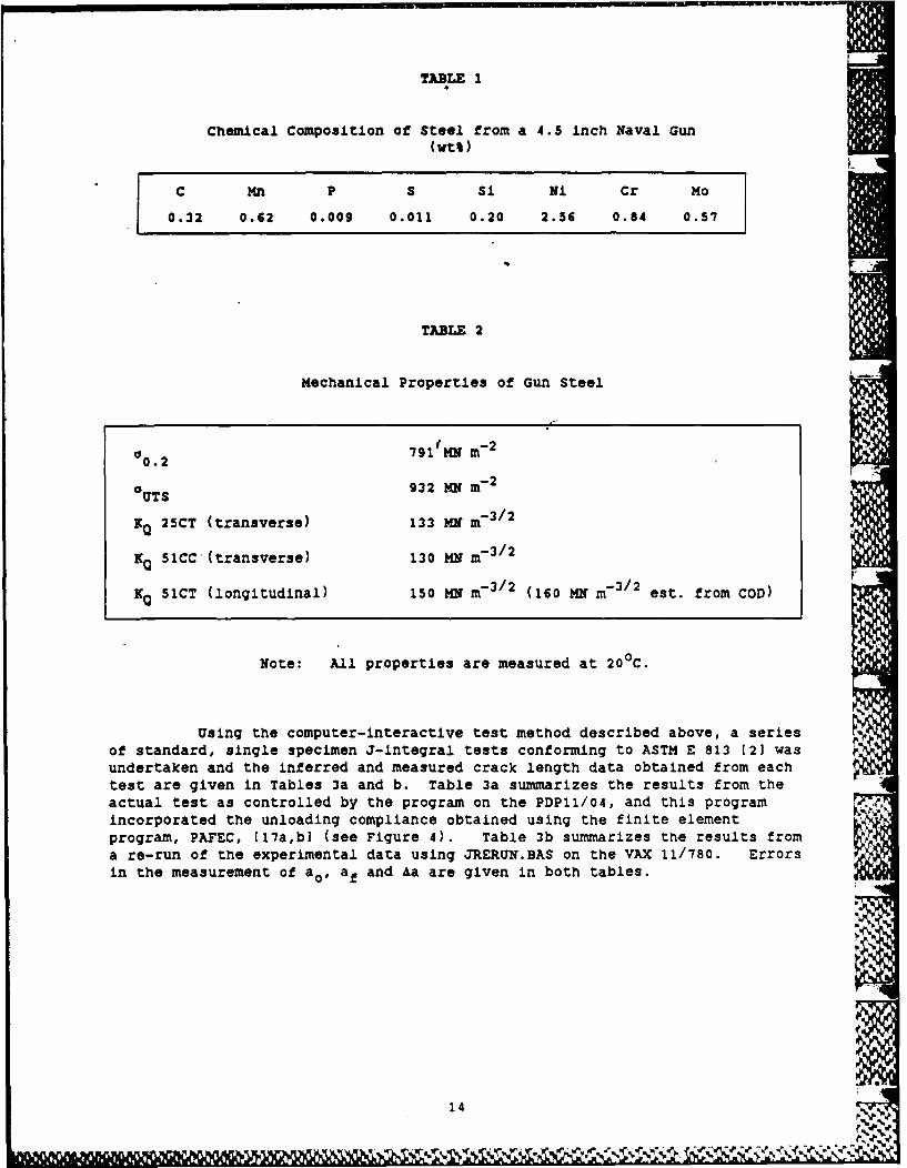
TABLE 1
chemical Composition of Steel from a 4.5 inch Naval Gun(wt%)
L •
C Mn P S Si Ni Cr Mo
0.32 0.62 0.009 0.011 0.20 2.56 0.84 0.57
TABLE 2
Mechanical Properties of Gun Steel
00.2 791 tMN m -2
aoUT S 932 MNm- 2
K 25CT (transverse) 133 MN m- 3/2
NQ 51CC (transverse) 130 MN M-3/2
KQ 51CT (longitudinal) 150 MN m-3/2 (160 MN m-3/2 est. from COD)
Note: All properties are measured at 200 C.
Using the computer-interactive test method described above, a seriesof standard, single specimen J-integral tests conforming to ASTM E 813 (21 wasundertaken and the inferred and measured crack length data obtained from eachtest are given in Tables 3a and b. Table 3a summarizes the results from theactual test as controlled by the program on the PDP11/04, and this programincorporated the unloading compliance obtained using the finite elementprogram, PAFEC, (17a,b] (see Figure 4). Table 3b summarizes the results froma re-run of the experimental data using JRERUN.BAS on the VAX 11/780. Errorsin the measurement of ao , af and Aa are given in both tables.
14
W,1 r?*
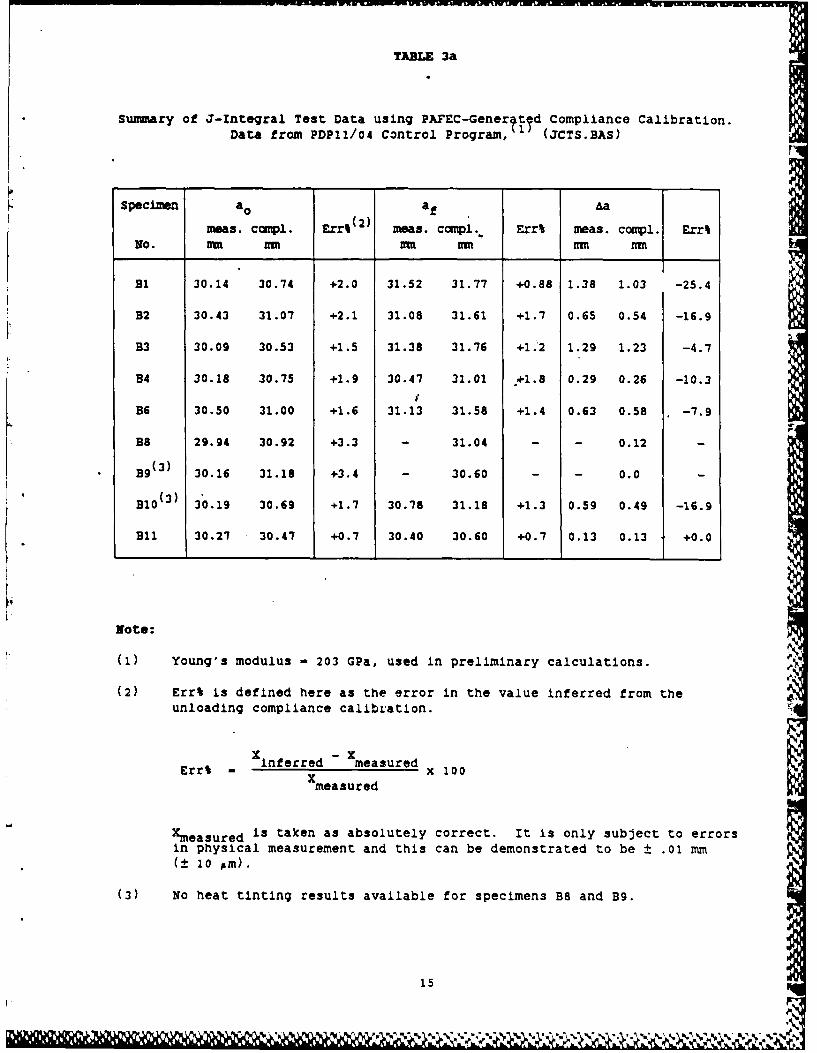
TABL 3a
summary of J-Integral Test Data using PAFEC-Generftyd Compliance Calibration.Data from PDP11/04 Control Program,,1 (JCTS.BAS)
Specimen ao af Aa
meas. compl. Err% (2 ) meas. compl.. Err% meas. compl. Err%No. M m VM m mu mu
BI 30.14 30.74 +2.0 31.52 31.77 +0.88 1.38 1.03 -25.4
B2 30.43 31.07 +2.1 31.08 31.61 +1.7 0.65 0.54 -16.9
B3 30.09 30.53 +1.5 31.38 31.76 +1.2 1.29 1.23 -4.7
B4 30.18 30.75 +1.9 30.47 31.01 +1.8 0.29 0.26 -10.3
B6 30.50 31.00 +1.6 31.13 31.58 +1.4 0.63 0.58 -7.9
B8 29.94 30.92 +3.3 - 31.04 - - 0.12 -
B9 (3 ) 30.16 31.18 +3.4 - 30.60 - - 0.0 -
B10 (3 ) 30.19 30.69 +1.7 30.78 31.18 +1.3 0.59 0.49 -16.9
B11 30.27 30.47 +0.7 30.40 30.60 +0.7 0.13 0.13 +0.0
Note:
(1) Young's modulus - 203 GPa, used in preliminary calculations.
(2) Err% is defined here as the error in the value inferred from theunloading compliance calibration.
Err% - inferred xmeasured x 100
Xmeasured is taken as absolutely correct. It is only subject to errorsin physical measurement and this can be demonstrated to be ± .01 mm(± 10 0,m).
(3) No heat tinting results available for specimens B8 and B9.
15
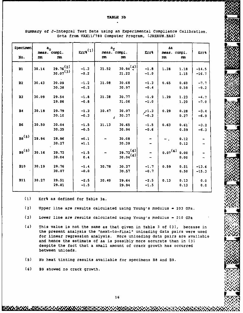
TABLE 3b
summary of J-Integral Test Data using an Experimental Compliance Calibration.D'ta from VAX11/780 Computer Program, (JRERUN.BAS)
Specimen aO af Aameas. compl. Err,(1) meas. compl. Err% meas. compl. Err%
No. Mu mm mu Mr rm mm
(2) (4)Bi 30.14 29.76(2) -1.3 31.52 30.94 4 -1.8 1.38 1.18 -14.5300(3) i30.07 -0.2 31.22 -1.0 1.15 -16.7
B2 30.43 30.09 -1.2 31.08 30.68 -1.3 0.65 0.60 -7.730.38 -0.2 30.97 -0.4 0.59 -9.2
B3 30.09 29.54 -1.8 31.38 30.77 -1.9 1.29 1.23 -4.729.86 -0.8 31.06 -1.0 1.20 -7.0
B4 30.18 29.79 -1.3 30.47 30.07 -1.3 0.29 0.28 -3.430.10 -0.3 30.37 -0.3 0.27 -6.9
B6 30.50 30.04 -1.5 31.13 30.65 -1.5 0.63 0.61 -3.230.35 -0.5 30.94 -0.6 0.59 -6.3
B8(5 ) 29.94 29.96 +0.1 - 30.08 - - . 0.12 -30.27 +1.1 30.39 - 0.12 -
B9(5 ) 30.16 29.72 -1.5 - 29.72(6) - 0.0? (6) 0.00 -30.04 0.4 30.04(6) - 0.00 -
B10 30.19 29.76 -1.4 30.78 30.27 -1.7 0.59 0.51 -13.630.07 -0.0 30.57 -0.7 0.50 -15.3
BI 30.27 29.51 -2.5 30.40 29.64 -2.5 0.13 0.13 0.029.81 -1.5 29.94 -1.5 0.13 0.0
(1) Err% as defined for Table 3a.
(2) Upper line are results calculated using Young's modulus - 203 GPa. b
(3) Lower line are results calculated using Young's modulus - 210 GPa
(4) This value is not the same as that given in Table 3 of (3], because inthe present analysis the "next-to-final" unloading data pairs were usedfor linear regression analysis. More unloading data pairs are availableand hence the estimate of Aa is possibly more accurate than in (3]despite the fact that a small amount of crack growth has occurredbetween unloads.
(5) No heat tinting results available for specimens B8 and B9.
(6) B9 showed no crack growth.
16
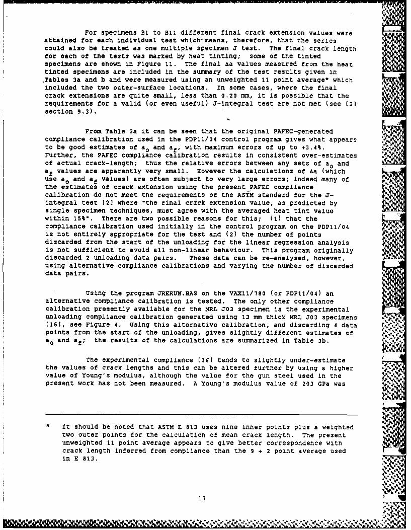
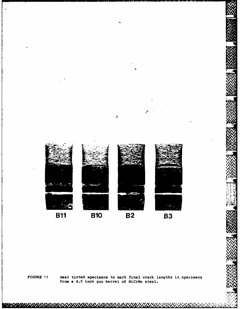
For specimens BI to Bli different final crack extension values wereattained for each individual test which-means, therefore, that the seriescould also be treated as one multiple specimen J test. The final crack lengthfor each of the tests was marked by heat tinting; some of the tintedspecimens are shown in Figure 11. The final Aa values measured from the heattinted specimens are included in the summary of the test results given In.Tables 3a and b and were measured using an unweighted 11 point average* whichincluded the two outer-surface locations. In some cases, where the finalcrack extensions are quite small, less than 0.20 mm, it is possible that therequirements for a valid (or even useful) J-integral test are not met (see [2]section 9.3).
From Table 3a it can be seen that the original PAFEC-generatedcompliance calibration used in the PDP11/04 control program gives what appearsto be good estimates of ao and af, with maximum errors of up to +3.4%.Further, the PAFEC compliance calibration results in consistent over-estimatesof actual crack-length; thus the relative errors between any sets of a0 andaf values are apparently very small. However the calculations of Aa (whichuse ao and af values) are often subject to very large errors; indeed many ofthe estimates of crack extension using the present PAFEC compliancecalibration do not meet the requirements of the ASTM standard for the J-integral test (2] where "the final cra'ck extension value, as predicted bysingle specimen techniques, must agree with the averaged heat tint valuewithin 15%". There are two possible reasons for this; (1) that thecompliance calibration used initially in the control program on the PDPll/04is not entirely appropriate for the test and (2) the number of pointsdiscarded from the start of the unloading for the linear regression analysisis not sufficient to avoid all non-linear behaviour. This program originallydiscarded 2 unloading data pairs. These data can be re-analysed, however,using alternative compliance calibrations and varying the number of discardeddata pairs.
Using the program JRERUN.BAS on the VAXll/780 (or PDP1l/04) analternative compliance calibration is tested. The only other compliancecalibration presently available for the MRL J03 specimen is the experimentalunloading compliance calibration generated using 13 mm thick MRL J03 specimens(161, see Figure 4. Using this alternative calibration, and discarding 4 datapoints from the start of the unloading, gives slightly different estimates ofao and af; the results of the calculations are summarized in Table 3b.
The experimental compliance (161 tends to slightly under-estimatethe values of crack lengths and this can be altered further by using a highervalue of Young's modulus, although the value for the gun steel used in thepresent work has not been measured. A Young's modulus value of 203 GPa was
It should be noted that ASTM E 813 uses nine inner points plus a weightedtwo outer points for the calculation of mean crack length. The presentunweighted 11 point average appears to give better correspondence withcrack length inferred from compliance than the 9 + 2 point average usedin E 813.
1'7
used for the normalization of the data in the experimental determination ofthe unloading compliance calibration but a value of 210 GPa may be moreappropriate for the thick specimens used in the J-integral testing ofspecimens B-B11. Both Young's modulus values are used for the calculationspresented in Table 3b. While an E value of 210 GPa appears to give a closercorrespondence with the heat tinting data there is a greater relative errorbetween a0 and af values using this higher E and, as a result, slightly largererrors in the estimations of the &a values. Over-all the use of theexperimental unloading compliance data [161 in the J-integral test offers abetter correspondence (smaller Err% values) between the inferred crack lengthvalues and those measured from heat tinted specimens than is achieved usingthe original PAFEC-generated unloading compliaace calibration.
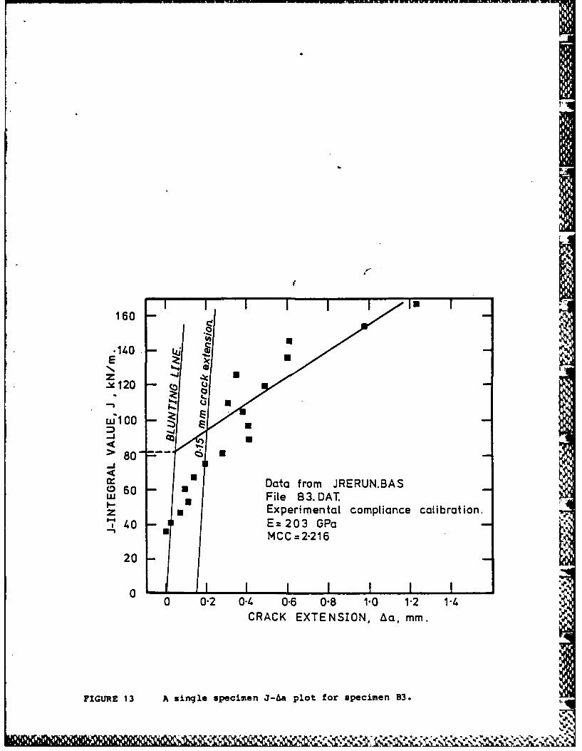
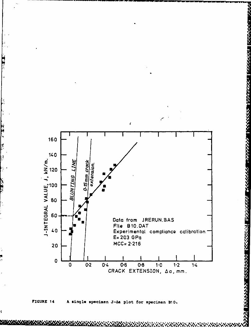
Typical J-Aa plots for the single specimen test methods are shown inFigures 12, 13 and 14. These plots used J-Aa data pairs generated byJRERUN.BAS on the VAX11/780.
The blunting line used in all calculations is given by equation 16,and is included on all J-Aa plots.
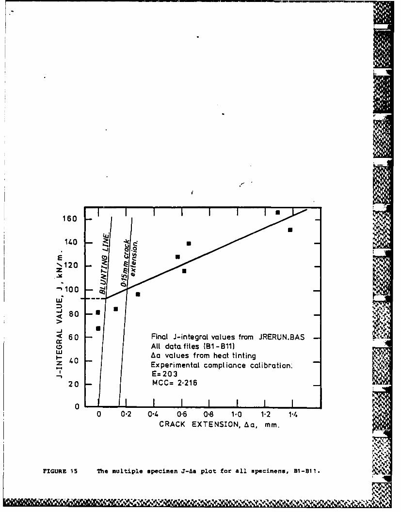
As mentioned above, the series of specimens B1 to Bli can also betreated as one multiple specimen J-integral test on this gun barrel steel.The af values used in this method are those obtained from the heat tintingexperiments and the J values corresponding to each final Aa value werecalculated from the area under the load/load-line-displacement record at thestart of the final unload of each test. The J-ha plot for these data is shownin Figure 15.
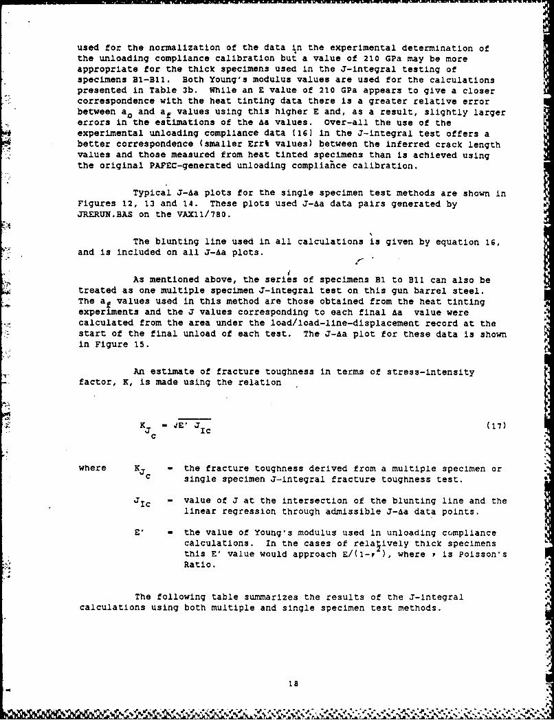
An estimate of fracture toughness in terms of stress-intensityfactor, K, is made using the relation
K 4 ,E' J (17)3 Icc
where Kc - the fracture toughness derived from a multiple specimen orc single specimen 3-integral fracture toughness test.
J3c - value of J at the intersection of the blunting line and thelinear regression through admissible J-Aa data points.
E' - the value of Young's modulus used in unloading compliancecalculations. In the cases of relatively thick specimensthis E' value would approach E/(1-, ), where P is Poisson'sRatio.
The following table summarizes the results of the J-Integralcalculations using both multiple and single specimen test methods.
18
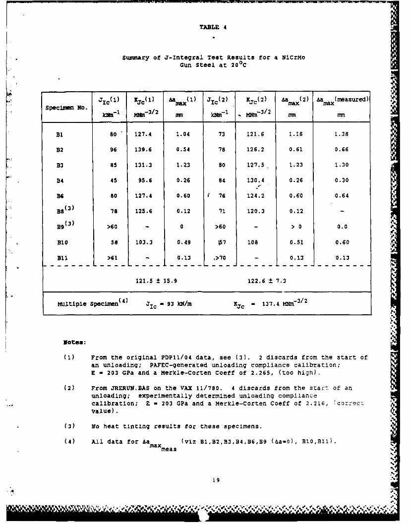
TABLE 4
Summary of J-Integral Test Results for a NICrMoGun Steel at 200 C
JIC(1) KIjC(1) Aamax( 1) J IC(2) Kjc(2) a ax(2) Aama"(measured)Specimen No. ~3/ - -_ _jami- 1 Miat- 3 / 2 t )aarl . Ma' - 3 / 2 .,m ffm
B1 80 127.4 1.04 73 121.6 1.18 1.38
B2 96 139.6 0.54 78 126.2 0.61 0.66
B3 85 131.3 1.23 80 127.5 1.23 1.30
B4 45 95.6 0.26 84 130.4 0.26 0.30
B6 80 127.4 0.60 [ 76 124.2 0.60 0.64
B8(3) 78 125.6 0.12 71 120.3 0.12 -
B9(3) >60 - 0 >60 - > 0 0.0
B10 58 103.3 0.49 07 108 0.51 0.60
Bli >61 - 0.13 >70 0.13 0.13
121.5 ± 15.9 122.6 ± 7.3
Multiple Specimen (4) Ic" 93 N/m Kjc - 137.4 bMg - 3/2
Notes:
(1) From the original PDP11/04 data, see (3]. 2 discards from the start ofan unloading; PAFEC-generated unloading compliance calibration;E - 203 GPa and a Merkle-Corten Coeff of 2.265, (too high).
(2) From JRERUN.BAS on the VAX 11/780. 4 discards from the start of anunloading; experimentally determined unloading compliancecalibration; E - 203 GPa and a Merkle-Corten Coeff of 2.216, correc:value).
(3) No heat tinting results for these specimens.
(4) All data for Aa (viz B1,B2,B3,B4,B6,B9 (Aa-0), B10,B11).maxmeas
19
ww"MMMMV
The results of the calculations of J1 c' given in Table 4, for twomethods of analysis show that the control program, JCTS.BAS and thearithmetically more accurate JRERUN.BAS produce similar JIc values. Sometests such as B9 and B10 give measurably lower JIc values than the remainingbulk of the tests. The reason for this is not apparent because the same testmethod and data analysis was applied to these specimens, and hence it must beconcluded that specimens B9 and BIO are representative of the lower toughnessvalues inwhat may be normal scatter for this material, viz. Kjc - 122.6 ±
7.3 MN M
From the results summarized in Table 4 it can be seen that themultiple specimen test gives a higher JIc value than the series consisting ofsingle specimen tests. This difference arises because of distribution of theJ-Aa data points between the 0.15 and 1.50 mm exclusion lines. The multiplespecimen test has these points evenly distributed between the exclusion lines,but in the cases of the single-specimen tests these data are often closer tothe blunting line, thus producing lower JIc values. Despite limited multiplespecimen J-integral data both the single specimen and multiple specimen Kjcvalues agree well with the known K0 values of the gun steel. Unfortunately,there are no KIc values, but because the Pmax/P5 values for the test areapproximately 1.12 (261, then the comparison between the Kjc values measuredin the present work and the known K0 v&lues is not unreasonable.
These preliminary JIc tests using the gun steel highlight somedeficiencies In the computer-interactive single specimen J-integral testmethod, but these can be overcome by the use of JRERUN.BAS. The firstdeficiency is that JCTS.BAS should discard more than two unloading data pairsfor the linear-regression analysis since there is evidence of non-linearbehaviour within the first four data pairs. This contributes to errors incrack length measurement, although this would not readily be apparent in the"rounding off" of data to 2 decimal points. Another deficiency is that withinJCTS.BAS the correlation coefficient for the linear regression analysis should J,
be calculated and documented.* At the present stage of development this isonly handled by JRERUN.BAS. A further limitation of the JCTS.BAS program isits lack of generality; certain lines within the program have to be edited iftest parameters are changed; e.g. discards of data pairs in the linearregression, compliance calibration and displacement calibration. At a laterstage of development the program could be expanded for these to be writteninto the program interactively.
Those factors which influence the accuracy of the measurements andcalculations are discussed in Section 10.
* Limited TPA of PDP 11/04 does not permit these calculations to beundertaken.
20
9. FURTHER APPLICATIONS OF THE COMPUTER-INTERACTIVE,
SINGLE SPECIMEN J-INTEGRAL TEST METHOD
At its present level of development this test method has been usedfor the measurement of the fracture toughness, JIc, of 6 mm thick MRL J03specimens of a precipitation hardened martensitic stainless steel, STA60,(271. The results presented in (271 were found to behave similarly to thosedata reported for 17/4 PH, (22]. The greatest difficulty encountered with thetest method was that the unloading compliance calibrations used in the work,PAFEC-generated in JCTS.BAS and experimentally measured in JRERUN.BAS, couldnot accommodate the large degree of crack tun6elling which occurred in thetesting of the STA6O. This problem is one which has not been addressed by thedevelopers of unloading compliance J-integral test methods.
A second application of the computer-interactive, single specimen J-integral test method was in the measurement of the fracture toughness, JIc' ofa 105 mm gun tube (non-autofrettaged) of NiCrMo steel. In this work (281 itwas possible to determine the plane-strain fracture toughness, KIc , of thesteel, with which to compare the JIc value obtaine i from JCTS.BAS, as Kjc.The agreement between KIC and Kjc was particularly good. Crack tunnelling inthis series of tests was minimal, and hence agreement between inferred andmeasured Aa values generally conformed to ASTM E 813 (2].
These applications of the computer-interactive, single specimen J-integral test method have demonstrated Its suitability for the testing of highstrength steels.
10. DISCUSSION
The limited TPA of the PDP11/04 used in the present experimentsmeant that error and accuracy checks as specified in (21 could not beundertaken during the test. Thus most of the accuracy checks have to beundertaken retrospectively using the JRERUN.BAS program and this makes the J-integral test method developed in this work similar to the KIc test [1], wherea completed test can be declared invalid on the basis of retrospectiveanalysis. ..
The standard (2] requires that the initial linear-elastic slope beused as a guide for the accuracy of the initial test set-up. If the PDP11/04 1control program were to check the loading compliance following the elasticload-up (Z9-1), then it would be essential for the elastic load limit of thetest to be set to the maximum final pre-cracking load of the specimen. Thismeans that if the test were found to be progressing incorrectly then it couldbe stopped and re-started without the need for further pre-cracking, i.e. thespecimen would still satisfy the final pre-cracking requirements for a validtest. Unfortunately, this load is relatively low. For example, in the caseof the gun steel (Section 8) the elastic load limit would be 25 kN or lower!
21
N Z.'o N.,&-' ~ ~ ~ ~ ~~ ~ ~~~~~~~~ I. ,. o ,,> ' , . - ' - ,. -
In the present method the specimens are checked for dimensionalaccuracy and so it can be assumed that-if the clip gauge seats correctly inthe specimen then errors in the load/load-line-displacement record will beminimal. (Correct seating of the clip gauge can be checked using very smallpre-loads and unloads.) The alignment of the test machine is also checkedprior to starting a series of J-tests. It is considered, therefore, that the.preliminary check of the compliance is not necessary. Any discrepancies incompliance with the experimentally-determined value can probably beaccommodated by small changes in Young's modulus in JRERUN.BAS (see below).This check of the initial linear elastic compliance is done indirectly by theJRERUN.BAS program. It can be shown that a ± 7% variation in normalizedcompliance at a/W - 0.60 produces a ± 2.3% variation in inferred a/W value,or, for a 25 mm thick specimen, a crack length of 30.60 mm ± 0.70 MM. Withthe exception of specimens B8 and B9, the initial crack length estimates inTable 3(a) fall within this range suggesting that most tests were correctlyset-up.
The area calculation check in the linear-elastic loading region isconsidered more important than the linear-elastic loading compliance (above)because it will give an indication of the errors in the area under theload/displacement curve introduced by the area calculation. This can bechecked further against the analogue Olot (see below). To undertake thisnumerical check, it is desirable that the elastic load limit, P7, be set ashigh as possible at the start of the test so that a relatively large area ismeasured and checked against a calculated area (area of a triangle in theelastic region). In the present form of the test control program this elasticload limit is usually set higher than the maximum fatigue load (for the final7.6 mm of crack growth) and this precludes the re-use of the specimen if atest does not proceed for any reason. Experience wlth steels has shown,however, that with the present instrumentation and level of development of thetest method, preliminary compliance checks are unnecessary, and that oncestarted the test should not be interrupted. The preliminary J-integral testsconducted on the gun steel revealed a slight error in the calculation of thearea under the load/load-line-displacement record, producing an over-estimateof this area in the linear elastic region up to load P7 (see Table 5below). This has been modified and now most MRL J03 specimens give an errorin the elastic region of less than +2.0% (27,281. The magnitude of error iscalculated by the ACCESS.BAS program on the PDP 11/04. This particular errorcheck gives a good indication of the accuracy of the area measurement in theinitial stages of the test where, because of the slope of the load/load-line-displacement record, the calculation errors should be the largest of the test.This may also give a measure of the non-linearity which is observed at thestart of most fracture toughness tests.
A check against the area under the analogue load/load-line-displacement records for specimens B-Bli, using a Kontron Bildanalyse Mini-MOP for area determination, shows good agreement between the calculated andmeasured areas. These are summarized in Table 5. It is not possible todetermine errors for the computer-calculated areas because there are nomeasured areas which are absolutely correct. The areas measured from theanalogue plots are subject to undetermined errors (but which are likely to besmall anyway). These are, for example, the accuracy of the analogue plot(pen thickness, linearity of scales calibration, etc.) and the accuracy ofusage of the Mini-MOP, see Table 5. Within these limitations, the agreement
22
V.%
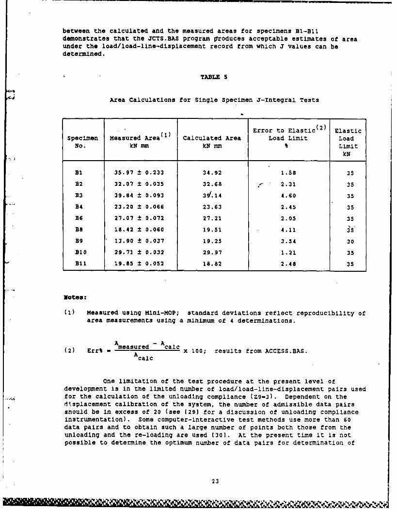
between the calculated and the measured areas for specimens Bl-Blidemonstrates that the JCTS.BAS program produces acceptable estimates of areaunder the load/load-line-displacement record from which J values can bedetermined.
TABLE 5
Area Calculations for Single Specimen J-Integral Tests
() Error to Elastic (2 ) ElasticSpecimen Measured Area Calculated Area Load Limit LoadNo. kN mm kN mm Limit
kN
BE 35.97 ± 0.233 34.92 1.58 35
B2 32.07 ± 0.035 32.68 2.31 35
B3 39.84 t 0.093 311.14 4.60 35
B4 23.20 ± 0.066 23.63 2.45 35
BE 27.07 ± 0.072 27.21 2.05 35
B8 18.42 ± 0.060 19.51 4.11 35
B9 13.90 ± 0.037 19.25 3.54 30
B10 29.71 0.032 29.97 1.21 35
Bli 19.85 ± 0.052 18.82 2.48 35
Notes:
(1) Measured using Mini-MOP; standard deviations reflect reproducibility ofarea measurements using a minimum of 4 determinations.
Ameasured - calc(2) Err% - A x 100; results from ACCESS.BAS.A calc
One limitation of the test procedure at the present level ofdevelopment Is in the limited number of load/load-line-displacement pairs usedfor the calculation of the unloading compliance (Z9-3). Dependent on thedisplacement calibration of the system, the number of admissible data pairsshould be in excess of 20 (see [29] for a discussion of unloading complianceinstrumentation). Some computer-interactive test methods use more than 60data pairs and to obtain such a large number of points both those from theunloading and the re-loading are used (301. At the present time it is notpossible to determine the optimum number of data pairs for determination of
23
the unloading compliance of the specimens; however, to assist in theassessment of the over-all acceptability* of data, the linear regressioncalculations within JRERUN.BAS also give the coefficient of determination, r2,for each estimate of unloading compliance. Ideally, this value should be inexcess of 0.9999,122], however, for the BI-Bl1 series undertaken In this workmost of the linear regression calculations for each unloading give values inexcess of 0.999. A typical output from JRERUN.BAS is given in Appendix 5,where it can be seen that the coefficients of determination for unloadingcompliance data are in excess of 0.999. If an increase in the number of datapairs for the unload is found to be desirable then, in the cases of specimengeometries for which the present J-integral test control program has beendeveloped, this can be achieved simply by changing the span control of theMTS-810 system so that the number of bits from the MSG results in a smallerincrement in stroke.
Another potential source of error in the single-specimen J-integraltest method is in the non-linear unloading effects which occur with somematerials. This can introduce significant errors in the calculation ofunloading compliance [29] and also small errors in the estimation of areaunder the load/load-line-displacement curve. To allow for these non-lineareffects (time-dependent recovery) a "hold" in the dlsplacement is oftendesirable before unloading see [22 and 29]. The material tested in thispreliminary work was a high strength steel and as a result the non-lineareffects at the start of an unload are small. This can be seen in Figure 16,where several unloads are re-plotted by GRAPH (24] after running the datathrough ACCESS1.BAS on the VAX 11/780. It is noted that a very small degreeof non-linearity is evident at the top (start) of the unloading record. Toovercome the possibility that any data pairs which may constitute the non-linear part of the record are admitted to the regression analysis the controlprogram (JCTS for example) now discards the first 4 load/load-line-
- .displacement data pairs. In the case of the data analysis programs,JRERUN.BAS on the VAX 11/780 and the PDP 11/04, all data pairs are listedprior to linear regression analysis, and the data can be re-examined and thenumber to be discarded input before the calculations begin. The number ofdata pairs which are discarded can vary for successive unloads in theJRERUN.BAS program and hence is listed in the summary of the calculationsproduced by the program.
Errors in the estimations of Aa, and to a lesser extent thecalculation of J, can also arise as a result of electrical and mechanicalhysteresis in the load and displacement measurement systems. Using a 250 kNload cell, the load can be measured to within ± 1.0% and the displacement clipgauge has a maximum error of ± 0.1%. Electrical noise is minimised becauseeach load/load-line-displacement data pair is an average of 10 readings takenover 0.01 second.
Looking back to the data in Tables 3(a and b), generated by
* The acceptability of the data can be tested quantitatively on the basis of
the accuracy of predicted versus measured a and af values.
24
V '11
JRERUN.BAS, it can be seen that the agreement between measured and calculatedcrack length values is closer than those obtained using the PAFEC-generatedcompliance calibration for the MRL J03 specimens. The sensitivity of thecalculated results to the compliance calibration and Young's modulus valueused for the normalization of raw compliance data has been demonstrated inSection 8, and is clearly an important aspect of the appraisal of the testprocedure.
It is difficult to assess the accuracies to which the J-integralvalue and corresponding Aa value are measured. All aspects of thecalculations and error analyses must be documented during a test or in the re-run of the raw data through JRERUN.BAS.
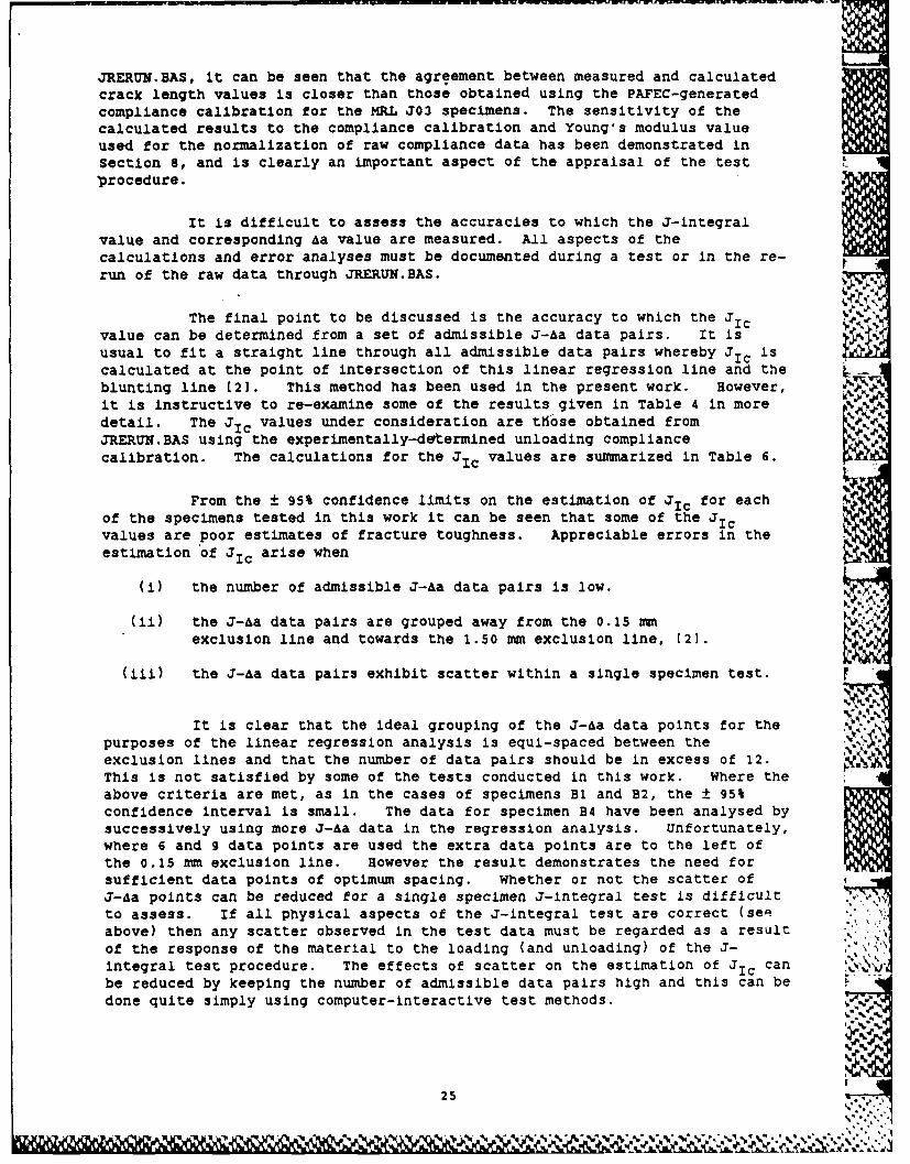
The final point to be discussed is the accuracy to which the JICvalue can be determined from a set of admissible J-Aa data pairs. It isusual to fit a straight line through all admissible data pairs whereby JIc iscalculated at the point of intersection of this linear regression line and theblunting line (2]. This method has been used in the present work. However,it is instructive to re-examine some of the results given in Table 4 in moredetail. The JIc values under consideration are those obtained fromJRERUN.BAS using the experimentally-determined unloading compliancecalibration. The calculations for the JIc values are summarized in Table 6.
From the ± 95% confidence limits on the estimation of JIC for eachof the specimens tested in this work it can be seen that some of the JICvalues are poor estimates of fracture toughness. Appreciable errors in theestimation of JIc arise when
(i) the number of admissible J-Aa data pairs is low.
(ii) the J-Aa data pairs are grouped away from the 0.15 mmexclusion line and towards the 1.50 mm exclusion line, [2].
(Iii) the J-Aa data pairs exhibit scatter within a single specimen test. r
It is clear that the ideal grouping of the J-Aa data points for thepurposes of the linear regression analysis is equi-spaced between the Aexclusion lines and that the number of data pairs should be in excess of 12.This is not satisfied by some of the tests conducted in this work. Where theabove criteria are met, as in the cases of specimens Bi and B2, the ± 95%confidence interval is small. The data for specimen B4 have been analysed bysuccessively using more J-Aa data in the regression analysis. unfortunately,where 6 and 9 data points are used the extra data points are to the left ofthe 0.15 mm exclusion line. However the result demonstrates the need forsufficient data points of optimum spacing. Whether or not the scatter ofJ-Aa points can be reduced for a single specimen J-integral test is difficultto assess. If all physical aspects of the J-integral test are correct (seeabove) then any scatter observed in the test data must be regarded as a resultof the response of the material to the loading (and unloading) of the J-integral test procedure. The effects of scatter on the estimation of JIc canbe reduced by keeping the number of admissible data pairs high and this can be Idone quite simply using computer-interactive test methods.
25
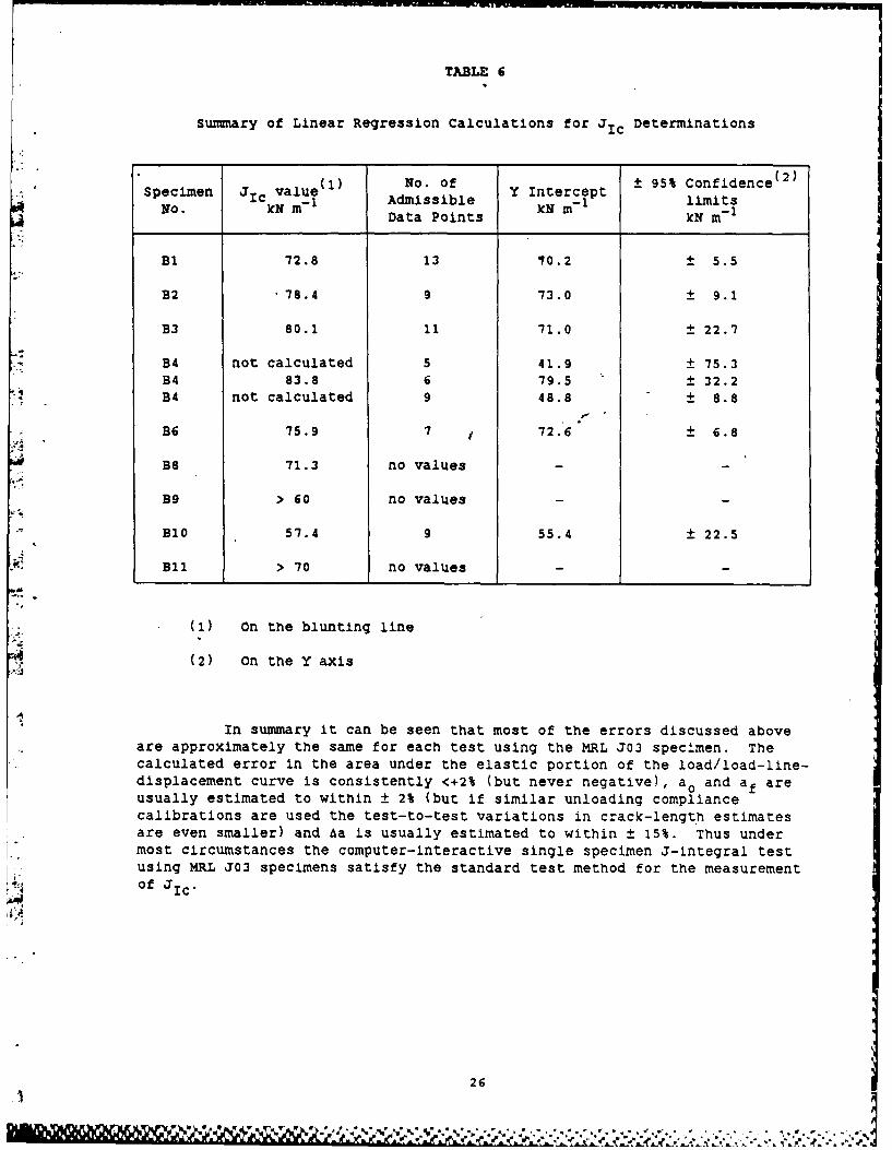
TABLE 6
Summary of Linear Regression Calculations for J Determinations
Specimen i value(1 No. of Y I 95% Confidence(2)-No. IckN M- 1 Admissible kN M- 1 limits
Data Points kN m-
B1 72.8 13 70.2 ± 5.5
B2 •78.4 9 73.0 t 9.1
B3 80.1 11 71.0 ± 22.7
B4 not calculated 5 41.9 t 75.3B4 83.8 6 79.5 ± 32.2B4 not calculated 9 48.8 ± 8.8
B6 75.9 7 72. 6 + 6.8
B8 71.3 no values
B9 > 60 no values - -
B10 57.4 9 55.4 ± 22.5
Bi1 > 70 no values
(1) On the blunting line
(2) On the Y axis
In summary it can be seen that most of the errors discussed aboveare approximately the same for each test using the MRL J03 specimen. Thecalculated error in the area under the elastic portion of the load/load-line-displacement curve is consistently <+2% (but never negative), ao and af areusually estimated to within ± 2% (but if similar unloading compliancecalibrations are used the test-to-test variations in crack-length estimatesare even smaller) and Aa is usually estimated to within ± 15%. Thus undermost circumstances the computer-interactive single specimen J-integral testusing MRL J03 specimens satisfy the standard test method for the measurementof J
26
11. CONCLUSIONS
A computer-interactive, single specimen J-integral test method hasbeen developed for the PDP11/04-MTS 810 system, and tested using the MRL J03specimen. The material under test was a NI-Cr-Mo 4.5 inch gun steel.
(1) The control program on the PDP11/04 has been shown to conduct asingle specimen J-integral test which produces Kjc values whichagree well with known plane-strain fracture toughness values.
(2) The inferred increments in crack length, Aa, obtained using theunloading compliance method incorporated in the control program areusually found to agree within +15% of that obtained by directmeasurement. Alternative calibrations and slight changes to theYoung's modulus value used in the calculations can be used toimprove the correspondence between measured and inferred values of
crack length.
(3) The computer-interactive single specimen,-J-integral test conforms tothe requirements of ASTM standard E 813 for the measurement of JIc"
12. ACKNOWLEDGEMENTS
The authors are indebted to Kr R. Farrara (27] of US Army ArmamentResearch and Development Command, Benet weapons Laboratory, for valuablediscussions which led to the refinement of the control program for the singlespecimen J-Integral test.'
we are also Indebted to Mr T.V. Rose for his pioneering programdevelopment for this work (31.
, '
27
t- PZe) S.ZP

!i . ... i i
iir
42 r linear elasticw/
I s
nonlnew zelne~intensely deformed
ir YII Lynr
WE-I
2 5.
FIGURE Schematic representation of crack-tip stress and strain fields.
.. %W+ q .WV
LL are a
0Li-
load-point displacement. 0.E
.x blunting
-
CRACK EXTENSION, mm.
FIGU7RE 2 ASTh E 813 method f or the measurement of j1 c.
It I
mm.,,,.
".. o
. .,= +:& U
4mU~ ! ,.. - 4. ,Z+_.4
,.., k; ": m O+ +
" w i" -4qi
"+ ' '"+,,",.,: ," .. ",,< -"" ",,' ,, ,, " '. . ",... . .. .. .- .- '"" -"e0,+ +: +,.++ ,.-,.?, .+, ,,+ '+-'..,, ... <,..:..,.+ +,U
II
AI
0-8
z
wa.K |~X 0-5 - m
n Experimentally determined compliancezz for MRLJ03 specimen.-J a
0-4 0 0 Normalized compliance fromASTM E 813.
30 60 90 120 150 180 210 240NORMALIZED COMPLIANCE.
FIGURZ 4 An experimental unloading compliante calibration for an MRL J03
specimen, data from 16]
I I I IMEW
0.8I
I-7
w
w
X05 an Normalized compliance determinedo E for MRLJO3 specimen using finitew element methods.
u004 0 Normalized compliance fromcr ASTM E 813.
-0-3
30 60 90 120 150 180 210 240NORMALIZED COMPLIANCE.
FIGURE 5 An analytical unloading compliance calibration for an mRL J03
specimen, data from (17a1.
11, 'II) AV I~
' I ' I
11.00
1200
1000
S800
600 -uJJ
-. J0
o 200
0 I , I I I0 0-2 04 6 0"8 1-0 1-2 1.4 1-6 1-8
DISPLACEMENT, (mm).
FIGURE 6 The opening and closing voltage output from an ITS 632.02C.20clip gauge.
.~ ~ ,~ ., . ~.~-~,~- , . ,.A .
DCa PE VL
P1ot Jlo VF Ia~
I~I
integrale test
Ram stok C*c compliance
back o VF
.20 bits MSG- 20 bits. 20 bits.
I -Z9=2"P5(2)-----------I-- -----
'Z9=2 Z9=3(unloading)9=4(reoading)
Z9=4(rezo2ding1Z9.2
I I-zg=3(unloading) I
SZ9 =4(reloading) i.w' . . . . .__
cP7 - -I
I 'I .I I I
I I I/ I I IZ9=1-"
I I I I
I I III I I I
(D7) 09(1 09(2) 09(3)LOAD - LINE- DISPLACEMENT, mm.
FIGURE 8 Loading, unload and re-load ramps in a single specimen J-integral test.
'XI
75
SPECIMEN Bi.
50
0 0-25 0.50 0-75 1-0 1-25LOAD LINE DISPLACEMENT, mm.
FIGURE 9 A typical force/load-line.displacement an~alogue output for asingle specimen J-inteqral test.
k ,A
-.-. 5.4, : / ...
FIGURE 10 Micrograph of a transverse section through a 4.5 inch Naval gun.O00OX 2% nital etch.
B11 B10 B2 B3
FIGURE 11 Heat tinted specimens to mark final crack lengths in specimensfrom a 4.5 inch gun barrel of NiCrMo steel.
K 0 N7

i"- .
,V
160 I I
.140E
-. z.x120 -.
-JJE>2IO0 Go U-.
280 -CC=2*216(. 60 'zl- 40 Im •Datal .Afrom JRERUN.BASsee AppendixIM
E= 203 GPa.20 -]MCC= 2"216. -14
0 L I I I I I0 0.2 0.4 0.6 0.8 1-0 1.2 1.4
CRACK EXTENSION, A., mm.
FIGURE 12 A single specimen J-Aa plot for specimen B.
C i ~ C ~ ~ * ~ ~ ~.;(.~ : , ~ *C* *~* ~ ~ *'%
160 -
.140 Fl w3DT
120
Ll 0 0 2 0. O6 8 1 2 1CRCMXESIN a m
FIUR 13 3 AsnlspcmnJa a ltf seie 3
160
140
z 120 .2
zt StU
> 80_j
CD 60 1
q.
w6 Data from JRERUN.BAS
z UFile B10.DAT~40 -Experimental compliance calibration-
E=203 GPa
20 -MCC= 2216
00 0-2 0-4 0.6 0-8 1-0 1-2 1.4
CRACK EXTENSION, A a, mm.
FIGURE 14 A single specimen J-ha plot for specimen B10.
160
E"12 0z
-;10
-j so
< 60 Final J-integral values from JRERUN.BAS0 All data files (B1-B11)w Aa values from heat tinting
Experimental compliance calibration.E=203
20 MCC= 2"216
0 0.2 0-. 0-6 0.8 1-0 1.2 1"4CRACK EXTENSION, Aa, mm.
FIGURE 15 The multiple specimen J-Aa plot for all specim~ens, BI-B1I.
&= y-'
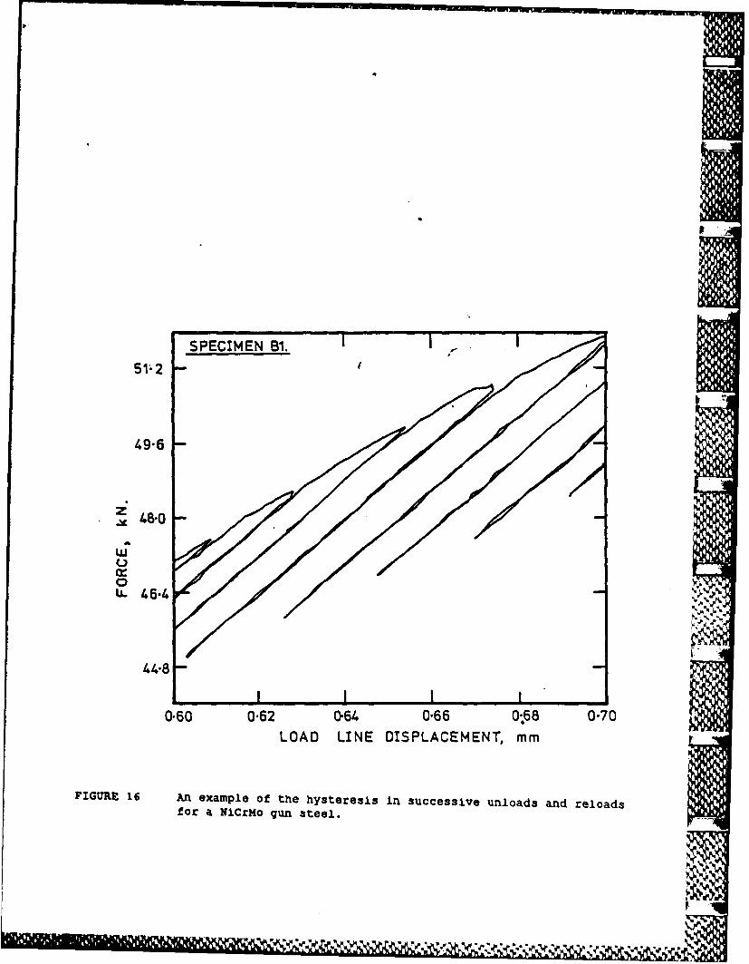
SPECIMEN B1.51* 2
49-6
U.46-4 V
44-8
0-60 0-62 0-64 0-66 0-.68 0-70LOAD LINE DISPLACEMENT, mm
FIGURE 16 An example of the hysteresis in successive unloads and reloadsfor a Nicrmo gun steel.
13. REFERENCES
1. American Society for Testing and Materials, (1985), Annual book of ASTMStandards 03.01, E399-83 Standard Test method for Plane StrainFracture Toughness of Metallic Materials.
2. ibid., E813-81 Standard Test Method for J1 c' A Measure of FractureToughness.
3. Rose, T.V. and Saunders, D.S., (1985), *An Automated, Single SpecimenJc Test". Proc. Australasian Institute of Metals Congress, Ballarat,1985, "pp C14-C16.
4. Rice, J.R., (1968), "A Path Independent Integral and the ApproximateAnalysis of Strain Concentration by Notches and Cracks". J. ofApplied Mechanics, 35, pp 379-386.
5. Rice, J.R., (1971), "Mathematical Analysis in the Mechanics ofFracture". in Fracture - An Advanced Treatise. (ed Liebowitz), Pub.Academic Press, New York, Vou. II, pp 191-311.
6. Begley, J.A. and Landes, J.D., (1972), "The J-Integral as a FractureCriterion". American Society for Testing and Materials, ASTM STP514, pp 1-20.
7. Rice, J.R. and Rosengren, G.F., (1968), "Plane-Strain Deformation Neara Crack Tip In a Power-Law Hardening Material". J. Mech. Phys.Solids, 16, pp 1-12.
* 8a. Hutchinson, J.W., (1968), "Singular Behaviour at the End of a TensileCrack in a Hardening Material" ibid, pp 13-23.
8b. Hutchinson, J.W., (1968), "Plastic Stress and Strain Fields at a CrackTip". ibid, pp 337-347.
9. Irwin, G.R., (1957), "Analysis of Stresses and Strains Near the End ofa Crack Traversing a Plate". Trans. ASME, J. of Applied Mechanics,24, pp 361-364.
10. Liu, H.W., (1983), "On the Fundamental Basis of Fracture Mechanics".
Eng. Fracture Mechanics, 17, pp 425-438.
11. Rice, J.R., Paris, P.C. and Merkle, J.G., (1973), "Some Further Resultsof J-Integral Analysis and Estimates". ASTM STP 536, pp 231-245.
12. Broek, D., (1982), In "Elementary Engineering Fracture Mechanics". Pub.
Martinus Nijhoff, The Hague, pp 240-242.
13. Rice, J.R. and Johnson, M.A. (1970). "The Role of Large Crack TipGeometry Changes in Plane Strain Fracture", in Inelastic Behaviourof Solids (ed. Kanninen), Pub. McGraw-Hill, pp 641-670.
28-.
14. Clarke, G.A., Andrews, W.R., Paris, P.C. and Schmidt, D.W. (1976),"Single Specimen Tests for JIc Determination" ASTM STP 590,pp 27-42.
15. Australian DSTO Materials Research Laboratories, Engineering DrawingNo. MRL-2772-01, 1984.
16. Clark, G., (1983), "Elastic-Plastic Fracture Toughness Testing of-* 4 Medium Strength Gun Steels", Proc. Workshop, Welding Institute,
Abington, U.K., June 1983, Sponsored by the Technical Co-OperationProgram, Sub-Group P, Technical Panel P-i, paper No. 2. - limitedrelease -
17a. Heller, K., (1984), Australian DSTO Aeronautical ResearchLaboratories, Private Communication.
17b. Heller, M. and Paul, J., (1985), "Numerical Compliance and StressIntensity Factory Calibrations of MRL Compact Specimens". ARL-Structures Technical Memorandum 421.
18. Saxena, A. and Hudak, S.J., (1978), "Review and Extension of ComplianceInformation of common CrackGrowth Specimens". Int. J. of Fracture,14, pp 453-468.
19. Newman, J.C., (1976), - Crack Opening Displacement in Center Crack,Compact and Crack Line Wedge Loaded Specimens", NASA Technical Note,D-8268.
20a. Digitial Equipment Corporation BASIC-l1 Reference Manual, 1975.
20b. MTS Multi-User Basic Initialization Guide, MTS Corporation, 1979.
21. Merkle, J.G. and Corten, H.T., (1974), "A J-Integral Analysis for theCompact Specimen, Considering Axial Force as well as Bending
* Effects", Trans. ASME, J. of Pressure Vessel Technology, 96, pp 286-292.
22. Joyce, J.A. and Gudas, J.P. (1979), "Computer Interactive JIc Testingof Navy Alloys", ASTM STP 668, pp 451-468.
23. Clarke, G.A. and Brown, G.M. (1980), "Computerized Methods for JIcDetermination using Unloading Compliance Techniques", ASTM STP 710,pp 110-126.
24. Kennett, S.R., (1984) "The Interactive Plotting program-GRAPH", MRLTechnical Note, MRL-TN-485.
25. Ritter, J.C. and Rea, T.W., (1977) "An Analysis of Crack OpeningDisplacement in Deeply Notched Specimens". J. Australasian Instituteof Metals, 22, pp 115-125.
26. Ritter, J.C. (1985), Private communication.
29
r*12e
27. Farrara, R. (1986), "Fatigue and Fracture Properties of a Semi-Austenitic, Precipitation Hardening Stainless Steel", MRL Report, inpreparation.
28. Saunders, D.S. and Burch, I.A. (1986), "Fatigue Crack Growth andFracture Toughness Assessment of a 105 mm Gun Tube for theAustralian Light Gun" MRL Report, to be published.
29. Clarke, G.A. (1981) "Single specimen Tests for JIc Determination-Revisited" ASTM STP 743, pp 553-575.
30. Smith, R.F. and Doig, P., (1985) "A Microcomputer Control System forSingle Specimen Fracture Toughness Testing Using the ElasticUnloading Compliance Technique". Eng.Fracture Mech., 22, pp 533-545.
30
Ah
naS
APPENDIX 1
COMPUTER PROGRAM LISTINGS FOR SINGLE SPECIMEN
J INTEGRAL FRACTURE TOUGHNESS TESTS
4"' (a) Program listings for PDP 11/04 Computer.
(1) JCTS.BAS
100 REM .. .AIJSTRALIAN GOVERNMENT DEFENCE SCIENTIFIC AND TEIVOLOGY ORGANIZATION110 REM ... MATERIALS RESEARCH LABORATORIES
120 REM JCTS.BAS130 TIME(10)140 EDW / BUIN('S*. LINE 2260I0 ERASE160 PRINT170 PRINT 'THIS PROGRAM rrS A SNGLE SPECIMEN J TEST'120 PRINT / PRINT 'THE TEST C(CMPLIES WITH ASTMig13190 PRINT / PRINT 'TE: READ THE QUESTIcNS CAREFULLY'200 PRINT ' FR A LISTING OF ALL PARAMETERS RLN "JLIST.BAS'210 PRINT '<> '; / Ino Zs
220 ERASE / PRINT * MrS ANALOG SET UP RoaINE / PRINT230 PRINT 'ENSURE:-'240 PRINT '- STRAIN CHANNEL IS Ct4FI' TO COMPUTER'250 PRINT '- STROKE CTRL ***** RAN UST BE *-10 M *
260 PRINT "- SPECIMEN our'
S270 N7-N71280 PRINT '- HYRAULICS ON'290 PRINT '- PRORAM CIrL IS LOCAL'300 PRINT / PRINT 'MASTER CLEAR (tiNL 4 MUST - 000),<CR>';
"',J 310 INPUT Zs / PRINT
320 PRINT 'SET PROGRAM CTRL TO REMOTE, <CR)
330 iNPUr Zs / PRINT340 PRINT 'ADJUST SET POINT TO GIVE ZERO DISP (CHNL3-000)'3S0 PRINT '***** WARNING
360 PRINT ' RAM WILL MDVE SO ENSURE CLEARANCE WITH STROKE ZERO'370 PRINT '<CR> '; / INPUT ZS / PRINT380 PRINT ' INSERT SPECIMN USING STROKE ZERO, <CR>390 INPUT Zs / PRINT400 PRINT 'SPAN 1 TO 1000.<c> '; / INu!" Zs / PRINT
410 PRINT 'INSTALL CLIP GAIUE (632.02C.20) AM ZERO (XJTPu'420 PRINT 'COARSE ZERO IS (N THE INPUT BOX AND FINE ZERO IS ON THE AMPLIFIER UNIT'430 PRINT '<R '; / INPUr ZS / PRINT
440 PRINT 'SET UP X-Y RECORDER FOR LOAD / DISP RECORD'." 450 PRINT 'USING CALIBRATED IOV POT ON 442 CONTROLLER'
460 PRINT 'INwU - 25 CM (HORIZ) - 5.0 V'470 PRINT 'c,> iHEN SET UP' / INPUT Zs480 ERASE / PRINT '0**** RANGE SELECTION -see, / PRINT490 PRINT 'LOAD RANGE (KN)'; / INPUT RO500 R0-2047/RO / REM RO ND V - BITS/KN
510 PRINT 'ENSURE 75% STRAIN RANGE IS SEILECTED.<C >
A1.1
520 INPUT Z$530 RIl1011 / EM 1011 BITS IS 1.0?4A ON THE 75% STRAIN RANE540 Fl-80 / REM RAMP RATE-80550 QUIT560 ENABL570 ERASE / PRINT 'TO STOP TEST <BREAK> *S" WILL LIXMP THRU LINEI 5460'580 PRINT "c(R> TO cXw'rINUE' / INPUr zs590 ERASE / PRINT 'o*** D/A ZERO READINGS * I PRINT600 P0-0 / DO-0610 GOSUB 1760 / RIM DACQ620 PRINT 'AVE LOAD - ';P0/(i0"R0);' KN (OR ';PO/10;' BITS)'630 PRINT "AVE LPD - ';DO/(10"R1);' MWt (OR ';DO/10;' BITS)'640 PRINT 'ZERO RESPECTIVE AMPLIFIER. REPEAT READINGS (Y/N)';650 INPUF Zs / IF Z$-'Y' THEN 600660 ERASE I PRINT '***** DATA STORAGE ' I PRINT670 PRINT / PRINT 'ENSURE DISK IS IN DYI:'680 PRINT 'SPECIMEN TITLE'; / INPUT TS690 OPEN 'DYI: '*T$ '.DAT' FOR OUI' AS FILE VF1 (20000)700 FOR Z-0 TO 20000 / VFI(Z)-0 / NEXT Z710 OPEN 'DYI: ' TS '.PLT' FR OUTPU AS FILE VF2(300)720 FOR Z-0 TO 300 / VF2(Z)-0 / NEXT Z730 OPEN 'LS:' FOR OUTPUT AS FILE #1 1740 ERASE / PRINT -o ';TS;' DIMENSINS * / PRINT750 PRINT 'SPEC WIDTH (METRES) -'; / INPUT W760 PRINT 'SPEC THICNESS (mERES) '; / INPUT B770 PRINT 'E (GPA) - '; / INPUT M780 PRINT 'PROOF STRESS (MPA) - '; / INPUT U790 PRINT 'MERKLE-CORTEN CO-EFFIC.': / INPUT Q800 M-MOI.00000E*09 / REM IN N/M 2810 PRINT / PRINT 'TO RETRIEVE ';T$;' J DkTA,RUN <ACCESS>'820 COPY830 VFI (0)-B / VFI(l)-W / VFI(2)-M / VFI(3)-RO VFI (4)-Rl-40 PRINT 'ELASTIC LIMIT (KN)'; / INPUT P7850 PRINT 'MAX. ' OF IILOADS'; /INplu u7860 PRINT '# OF BITS STROKE INC' / INPUT M7570 VF2(1)-P7880 P7-INT(P7*R0)890 N-0 / N1-0 / Z9-1 / Z-0 / D2-0 / N7-0900 ERASE / PRINT '** RAMP TO ';P7/RO;' KN THEN . TEST'910 PRINT PRINT 'X-Y READY, <CR> TO START TEST'; / INPUT Zs920 REM PRINT OF DATA FILE930 PRINT #1,TAB(10)'PILrING DATA FOR THE 10% UNLOAD i IjNEGRAL TEST FOR SPECIME-N ';T$940 PRINT *1,TAB(5)'READING #';TAB(20)'AREA';TAB(35) 'A/W' ;TAB(50)'DELTACRKLNGTH' ;TAB(75) 'J' ;TAB(S5) 'E5' ;TAB(100)'V'950 PRINT #1 ,TAB(21 )'KNM';TAB(54)'MEI'ES';TAB(72)'KN/M'960 REM SET UP GRAPHICS970 ERASE / GRCN9.80 PHYL(100,975,Ss,750)990 SCALE(0.0.2.00000E-03,0.350)
'4 1000 AXES(00) / AXES(2.00000E-03,350)
1010 LABEL(TS' DELTA A. METRES.',' I VALUEKNM' ,S.00000E-04,25,0)1020 INVEC / PLOT(0.0) / PLOT(200/(2'uJ1000) 250) / INVEC1030 INVEC / PLOT(I.50000E-03,0) / PLOT((200/(2*Ul1000))'1. 50000E-03,250) / INVEC
1040 (OSUB 1130 / REM RAMP ROUTINE1050 IF Z9-3 THEN GO TO 10401060 IF Z9-5 THEN GO TO 1040
Al .2
A C mL-
1070 GDSUB 1370 / REM FIT RWTriN1080 KUXR("-,F2(5N3).J)1090 PRINT*1,TAB(7);YF2(5*Nl);TAB(22);YF2(S*Nl'1);TAB(37);F2(5N12);TAB(52);VF2(5N13);TAB(70);VF2(5*Nl-4);TAB(85);E5;TAB(100);V1100 IF YF2(5*N13)>-.S0000E-03 ThHIN 2260 /REM our OF P100
* *.1110 IF N7>-U7 CD TO 22601120 CD TO 1040
* 1130 REM RAMW SUB-ROUTINE1140 IF Z9-5 THEN Z9-21150 DIM S(3)1160 0i Z9 GO TO 1180.1340,1500,16301170 REMd1180 REM RAMP sTRK up ON LoAD wAIQI (zg-i)1190 0-5-1 REM SO IS PRESENT STRK POSIMh1206 0-0Q DO-01210~ S-2 /S(o)-o S(1)-Fl / S(2)-S9
1220 FG(1.S.1.7,4)1230 FoR z-0 To 1000 / NEXT Z / RDA WAIT1240 N-N411250 GOSUB 1760 /REMd DACX1260 VFI(S'N)-N /VFI(5"N-1)-PS / VF1(S*N-2)-Ds /eVFI(5*N-4)-Z91270 IF N-I THEN VF1(5*N-3)-PS / CD To 13001280 P8-((PS-P4)/2)1290 VF1(5*N-3)-VFI(5*N-2)*(P8)*((DS)-D7)1300 D7-D5 / P4-P51310 IF PS>-P7 THN 17401320 S9-S9-1 / GO TO 12001330 REM
*1340 REM RAMP STROKE UP ON DELTA DISPL. WATCH (Z9-2)1350 D9-D5-M7 / REM D9-DIsPLAcEaw ENHD LEvEL1360 P0-0 /DO-01370 S-2 /s(o)-o / S(1)-Fl / S(2)-S91380 FG(1,S,1.7,4)1390 FO z-0 To 1000 / NExT Z / REM WAIT1400 N-N11410 CDSUE 1760 / REM TO DACXQ1420 Pg-((PS'P4)/2)1430 VF1(50N)-N / VFI(S"N1I)-PS / VFI(5'N-2)-D5 / F1(5SN-3)YF1(5*N-2)(P)((D)-D7)
YF (s*N-4)-Z9*1440 A3-VFI(5'N-3)
1450 D7-D5 P4-P51460 N5-N /REM LAST READi~r NUmBER AT LOAD up
* 1470 IF DS>-D9 T1HN 1740 / REM D9-NEW DISP LIMIT1480 S9-S9-1 / GO TO 13601490 REM
1500 REMRAMP DOM IAD WATCH (Z9-3)1510 N7-N7*11520 P9-.9*(PS) / D9-DS / REM D9 IS DISP AT START OF tlJLOAD1530 P0-0 /DO-01540 S-2 /S(0)0O / s(1)-FI / S(2)-S9
1550 FG(I.S.1.7,4)
1560 FOR Z-0 TO 1000 / NEXT Z / R34 WAIT1570 N-N'11580 CDSUB 1760 /REM DACQ
1590 YFI(5*N)-N / FI(s"N-1)-Ps VF1(s*N-2)-Ds / vF1(5*N-3)-A3 /VFI(5*N4)-Z9
Al .3
1600 IF PS<-P9 lIM~ 17401610 S9-S9-1 / WD TO 1530
1620 RBv!1630 RH! RAMP UP TO PIOR LEVEL (XN DISP WA112 (Z9-4)1640 P0-0 /DO-01650 S-2 /s(o)-o / S(1)-FI / S(2)-S91660 FG(1.S,1.7,4)1670 FOR Z-0 TO 1000 / NEXT Z / REW WAIT1680 N-N+I
1690 GOSUB 1760 /REW iDAC1700 VFI(5"N)-N /VFI(5*N41)-P5 /vF1(s*N-2)-Ds Vv1(S'N-3)-A3 I FI(5'N-4)-Z91710 IF DS>-D9 TlHN 1740
1720 S9-S9-1 GOC TO 16401730 REM1740 Z9-Z9-1 /RBI RAMP SWITCH
1750 RETURN1760 RE! '-DC1770 DIM P(I0),D(10)1780 FOR Z-0 TO 10 /P(Z-O / D(Z-0 /NEXT Z
*1790 DA(X(3,P,0.10) I rAC(3,D,1,o0)1800 START1810 IF P<10 MlEN 1810
1820 IF D10 flM~ 18201830 QU1IT1840 FO Z-0 TO 9 / PO-PO-P(Z) /DO-DO-D(Z) /NEXT Z1350 PS-POlIO / D5-DO/101860 RETURN1870 REhd STRAIGIT LINE FIT1880 X0-.0748S77 / X1-.0178943 /X2--2.30639E-041890 X3-1.S0063E-06 / X4--3.78693E-091900 K-RO/(RI*1.OOOOOE-06) / RPM scALiIK Fcro FOR VLIIP IN 1Id/!U1910 RB! SET SUvt44IONS TO ZERO
*1920 E1-0 / E2-0 / E3-0 / E4-0 / ES-0 / E6-0 / F-C1930 IF NI>-1 TM~ 20001940 AM1 US ING DAITA FROM! 1ST LOAD1950 FOR C-wNTC.9 N) To mrNCr(.1N) STEP -11960 E1-E1*YF1(S*C-1) / E2-E2-VFI(S*C-2) /E3-E3-VFI(S*CI)'YF1(S'C-2)1970 E4-E4-VF1(S*C-2) 2
1980 F-F+11990 NExT C / a) TO 20602000 RPM( USING DATA FROM 10% U.NLOAD2010 FOR C-(Ns.S) TO N STEP +12020 EI-E1*VFI(S*C-1) / E2-E2-VFI(5*C.2) /E3-E3*YFI(S*C-1)'YFI(5*C.2)2030 E4-E4-VFI(S'C-2) 2
2040 F"F~12050 NEXT C2060 REM! CALW OF SLOPE2070 ES-(E3-((E1*E2)/F))/(E4-(E2 2)/F)2080 V-(K*MD)/ES / REW NOERM. CCMPL.2090 R-X0*X1WV*X2*V 2*X3*V 3*X4*V 4
2100 YI-RW2110 IF NI>-2 MENJ 2210
2120 VF2(3)-YI2130 IF NI>-I TIIE 22102140 VF2(0)-Y1 / REM ORIGINAL CRAOCK LETH2150 REM! CALC OF Y INTERCEPT
Al .4
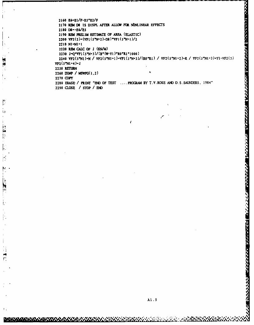
2160 E6-E 1/F-ES*E2/F2170 REM DI IS DISPL AFIUl ALLOWI FOR NtI4LINEAR EFFECTS2130 Dg--E6/ES2190 151 PMELI ESTIM4XE OF AREA (ELA.STIC)2200 YF2(2)-(YF1(S*N.2)-DS)*W(5SN1)/22210 NI1Nl12220 REM CAI.C OF J (Di/Id)2230 J-Q'VFI(ON-3)/(Br(W-Yl)lRO*RI*1O)2240 YF2(S0NI)-N / VF2(5Nl1)-VFI(5*N3)/(R0&R1I VF2(S@N1-2)-R / VF2(S'N1-3)-YI-YF2(3)
VF2(5N14)-J2250 REJnM2260 UMA / Iw6WFG(I,2)2270 CDPY2230 DRASE/ PRiNT END OF TEST ... .PROMRM BY T.V.ROSE AND D.S.SAUNDEKS, 1984"
2290 CLOSE /STOP /END~
Al1.5
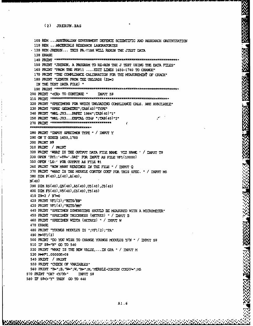
(2) JRERUN.BAS
100 R04 ...ATSRALTN GV T DECE SCIETM IC AND RESEARCH RGIIZATION110 REM M9TERIALS RESEARCH IABORATORIES120 REM ... THIS PRLMA1M WILL RERUN THE JTEST DATA130 RASE140 PRINIT150 PRINT "JRERI, A PROGAM TO RE-RUN THE J TEST USING TH DATA FILES"160 PRINT "FROM THE PDP11 .... EDIT LINES 1650-1740 TO CHANE"170 PRINT "THE COMPLIA C1XRAI FOR THE MEASUOR t OF CRACK"180 PRINT "LENTH FRQi THE UNIWADS (Z9-3IN THE TEST DAA FILE)"
190 PRIMT200 PRINT "<CR> TO CONTIUE INPUT Z$210 PRINT-220 PRINT "SPE7IS FOR WHICH UNMADING C=PLIANCE CALS. ARE AVAILABLE"230 PRINT "SPEE E0" ;TB(40)"TYPE"240 PRINT "MRL J03...PAEC 1984";TAB(40)"1"250 PRINT "MRL J03... EAL C AiP ";TAB(40)"2"270 PRINT
280 PRINT "IPUT SPirDE TYPE " / NPUT Y290 Ot; Y GOSUB 1650,1700300 PRIT W310 PRINT / PRINT320 PRINT 'WHAT IS THE OUTPUT DATA FILE NNE VIZ ME ' / DIPUT T$330 OPEN 'DY1:'+T$+'.DAT' FM INPUT AS FILE VF1(10000)350 OPE 'LS:' FCR OTPUT AS FILE #1360 PRINT "HOW MANY READINGS IN THE FILE " / INPUT 0370 PRINT "WHAT IS THE MERFZE CORTEN COEF FOR THIS SPEC. " / INpUT M5
380 DIM P(40),L(40),A(40),N(40)390 DM R5(40),Q5(40),A5(40),U5(.0),J5(40)
400 DIM FS(40),V5(40),C5(40),T5(40)410 Z9-2 / N7-0420 PRINT VF1(3);"BITS/IW"
430 PRINT vF1(4);"BITS/ -4"440 PR.r "SPEMEN DIMESIONS SHOJLD BE bMFqURE WITH A NICR "ETE"450 PRINT "SPECI N THICKNESS (MEIRS) " INPUT B460 PRINT "SPErIhE WIDTH ([MES) " / INPUT W470 ERASE480 PRINT "Y]US MODULUIS IS ";VFl(2);"PA"490 M-VF1(2)500 PRINT "DO YM WISH TO CHNG YCNS MODUIUS Y/N" / INUT S$510 IF S$-"N" GO TO 540520 PRINT "WHAT IS THE NEW VALUE, ... IN GPA" / INPUT M530 M"M*1.00000E+09540 PRINT / PR.IT
550 PRINT "CHECK OF VARIABLES" i560 PRINT "B"B, "W-" ;W, "M." ;M, "MfLE-CORTDN COE =" ;M5
570 PRINT "OK. <YIN>" INPUT S$580 IF S$<>"Y" T GO TO 440
Al. .6
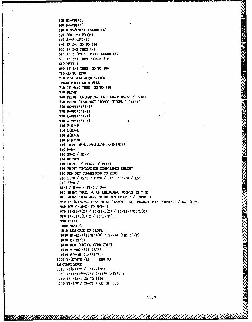
590 N3-VFI(3)600 N4-YFI (4)610 K-N3/(N4*1.OOOOOE-06)620 FOR 1-2 TO Q1l630 Z-vFI(SIl-1)640 IF Z-1 CD TO 630650 IF Z-2 DWN N-0660 IF Z-(Z9-I) fl4 GDSUB 380670 IF Z-3 IEN COSUB 710680 NEXT I690 IF Z-3 111FJ CD TO 810700 GD TO 1290710 REWI DATA ACQUISITIONFRC14 PDPI1 DATA FILE
720 IF NOG IENH (3) TO 760730 PRINT740 PIT 'UNLOADING3 COMPLIAC DAITA- PRINT750 PRINT 'READIN?" LOAD , DISPL. , AREA*760 N6-VF1(SI1-S)770 P-VFI(S*1-4)710 L-VFI(5*1-3)790 A-VF1(5*1-2)300 P(N)-P310 L(N)-L320 A(N)-A130 N(N)-N6140 PRINT N(N),P/N3.L/N4.A/(N3*N4)15 0 N-N*1360 Z9-Z / NS-N870 REJURN130 PwRN / PRINf / PRINT190 PRINT "UNLOADING COMPLIANCE RaLN'900 REWd SET SUMWIS TO ZERO910 E1-0 /E2-0 / E3-0 / E4-0 / ES-0 / E6-0920 E7-0/ES-0 / E9-0 / V1-0 / F-0930 PRINT %%dX. NO Of UNLOADIG POINTS IS -;NS940 PIT -HY MANY TO BE DISCARDED - / INPUT 0950 IF (Ns-O)<3 THHE PRINT ERRoRt .. .M)T eIxxI DATA PoITs!" GOC TO 940960 FR C-(0O) TO (N5-1)970 E1-E1-P(C) / E2-E2-L(C) / E3-E3-P(C)*L(C)930 E4-E4-L(C) 2 / E6-E6-P(C) 2990 F-F~l1000 NEXT C1010 REM CA.LC OF SLOPE1020 ES-E3-((E1*E2)/F) / E9-E4-((E2 2)/F)1030 ES-ES/E91040 REM CALC OF CORR CDEFF1050 YI-E6-((E1 2)/F)1060 E7-(E8 2)/(E9*W1)
1070 V-(K*MB)/ES RIM NDORM COMP'LIANCE1030 Vs(N7)-v / CS(N7)-E71090 R-X0*X1*V+X2*V 2+X3* 3+X4*V 41100 IF N7>-l CDTO 11201110 Y1-RW /YO-YI O D TO 1130
A1.7q
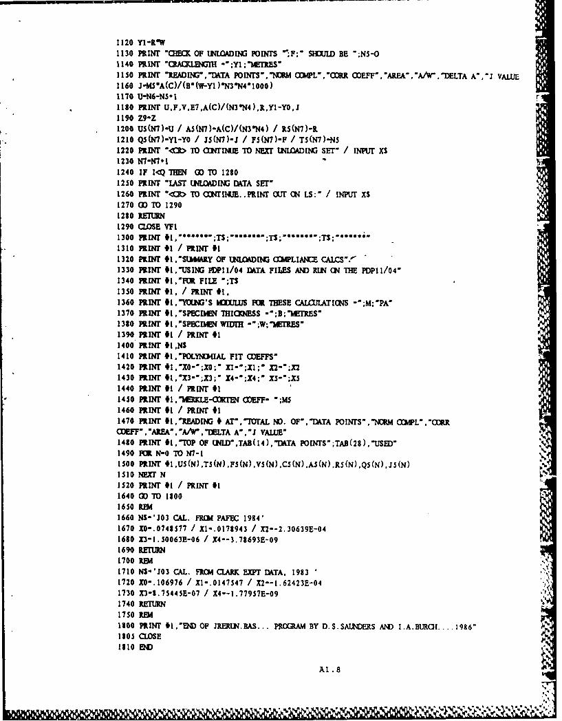
1120 Yl -1W1130 PRINT 'CEC OF UNLIOADING POINTS F;' SHULD BE ";NS-O1140 PRINT "CACLENGT -;Yl;"ETRES51150 PRINT "READING,'DTA POINSYNDM CPL','CORR. CEFF' 'AREA, AW.WDELTA A".J VALUE1160 J-fwSA(C)/(D*(W-Y)N3N41000)1170 U-N6-NS*11180 PRIN'T U,F,VE7,A(C)/(N3"N4),R,Y1-YO,J1190 Z9-Z1200 US(N7)-U / AS(N7)-A(C)/(N3*N4) / KS(N7)-R1210 QS(N7)-YI-YO / JS(N7)-J / FS(N7)-F / TS(N7)-NS1220 PRINT -<R To coNfiNuE To NExT UNLOADING3 SET-/ INPUT xs1230 N7-N7+11240 IF I<Q THENI GO TO 12801250 PRINT "LAST UI.LDING DATA SET"1260 PRINT *<R To aw1til(I. PRiNT ourT ON LS:-/ INPUT X$1270 GO TO 12901220 RETURN1290 CLOSE VFl1300 PRINT 1 ~ ;T s ;T ; S;1310 PRINT #1 / PRINr #I1320 PRINT *1 ,,suLmRY OF UNLOADING ooPLiAIc caLCS'f1330 PirIN #l,'USIII3 PDP1 1/04 DATA FILES AND UN ON~ THIE PDPI 1/04-1340 PRINT #I1.FO FILE ';TS1350 PRIN #1. / PRINT #t.1360 PRINT 1.'1iMM'S MULUS FOR THESE CALCULATIONS -;M;PA'1370 PRINT *1.'SPECIblEN THICKNESS -*;B;IMETRES"1380 PRINT fl1.SPCIAIW!I .'W;'M~rRES'1390 PRINT 11 / PRINT #I1400 PRINT #I,NS1410 PRINT *1.POLYND4IAL FIT COEF1420 PRINT #1,'X0-;X0;' XX';Xl;* X2-';X21430 PRIT #1.'X3-;X3;: X4-*;X4;* XS5";XS1440 PRINT 11 / PRIwr #II1450 PRIN *1.'MERKLE-lOTEN (fEFF- .;m41460 PRINT #1 / PRINT #I1470 PRINT #I,READING # AT-.-rAL No). OF,-DTA POINTS1IRM aCiL,-RRCEFF- * AREA * lA/W. MUTA A * J VALUE"1410 PRINT *i .TOP OF UNLD,TAB(14), -DATA POINTS,;TAB (2 8),-USED-1490 FOR N-0 70 N7-11500o PRINT #.US(N),TS(N).ps(N).vs(N),CS(N)A(N),RS(N)Q(N).Js(N)1510 NEXT N1520 PRINT #1 / PRINT #I1640 GO TO 13001650 REMl1660 NS-'J03 CAL. FR()4 PAFEC 1984'1670 XO-.0748577 / X1-.0178943 / X2--2.30639E-041630 X3-1.50063E-06 / X4--3.78693E-091690 RETUR1700 REM1710 NS-*Jo3 CAL. FR(I4 CLARK EX~r DATA. 19831720 XO-.106976 / X1-.0147547 / X2--1.62423E-041730 X3-8.75445E-07 / X4--l.77957E-091740 RETURN I
1750 REI1100 PRINT f1.'END OF IRERUN.BAS... PROCRAM BY D.S.SATJNERS AND I.A.BURGI.. 1986-1305 CLOSE1210 ED
A1 .8
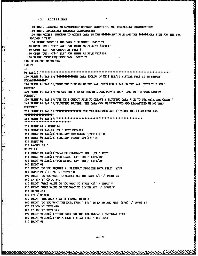
(3) ACCESS.BAS
100 RDA ... AUSIRALIAN GDVE ET, DEFENCE SCIENTIFIC AND 1TOLOGY ORGINIZATION110 REM ... ITERIALS RESEARO! LABORATOIES120 1.W Aa.SS PROMAM TO ACSS DATA IN TIE #ffM4IJ.I T FILE AND THE 444W9. RA FILE FOR THE 10%
INLOAD J TEST130 PRINT AT IS THE DKTA FILE NAME? * INPUr TS
140 OPEN 'DYI:'*TS*'.DkT' FOR INPUr AS FILE VFI(30000)150 OPEN 'LS: * FOR (UI'UI AS FILE #1160 OPEN DlY: ',T$S°.PLT ' F INPUT AS FILE VF2(S00)170 PRIIT 'Thu 3BEJiR? Y/IN, p ZS
180 IF ZS-'' 00 TO 270190 PRINT
200 PuIN 41.TAB(S);........T.I DATA STORM IN THIS PDP/Ii VIRTlUAL FILE IS IN BINARY
210 PRiNT 9I,TAB(5);"LOAD TME DISK 0N TO TIE VAX. THEN RUL V.BAS CN THE VAX. THEN THIS WILL
220 PRINT #1,TAB(5);*AN OUT PUT FILE OF TIE RIGINAL PP/I1 DATA, AND IN THE SAME LISTING
230 PRINT 9ITAB(s);-USE THIS CUflPU FILE TO (RATE A PLOTTING DATA FILE TO USE WITH THE RAPH240 PRINT 51 ,TAB(5);*PLOITING I Nl!!TIE. THE DATA CAN BE REPLOMTED AND REANALYSED USING THIS
250 PRINT #1,TAB(s);"'.I.EI"I.EEUUIII THE VAX BoUTINES ARE 1) V.BAS AND 2) A£ZESSI.BAS
260 PRINT 9ITAB(S) *
270 PRINT 1 ] PRINT #I280 PRINT #ITAB(20);TS;' TEST DETAILS"290 PRINT 9I.TAB(20)'SPCM THICKNESS ';VF(0);' M'300 PRINT 4I,TAB(20)'SPECmE WIM';VFI(1);' M'310 PtrN" 41320 0-VF1(3) /RI -VFl (4)330 PuNT #I,TAB(20)'SCALII( CCNSTANrS FOR ';T$;' TEST'340 PRINT #1,TAB(25)'P( LOAD. 10- ';RO*;' BITS/KN'
: 350 PRINT 9ITAB(25)'POR DISPL. Rl- ';Rl;' BITS/U'360 PRINT #1370 PRINT 'DO YOU REQUIRE A PRINTT FRC4 THE ITA FILE? (Y/N)'380 INPur zs / IF ZS-'N' THEN 740390 PRINT 'DO YU WANT T ACCESS ALL THE iTA Y/N' / INPUT ZS400 IF ZS-'Y' CD TO 440410 PRINT 'V.HAT VAL E DO YOU WANT TO START AT?' / INPUT v420 PRINT '"M.AT VALUE DO YOU WANT TO FINISH AT?' / INPUT W430 GO TO 450440 V-I / W-2000
• 450 PRINT 'THE [WTA FILE IS STOR IN BITS'* 460 PRINT '10 YOU WANT THE DATA FRO ';T3; ' IN KNM AND KW. (Y/N)' / INPUT YS
470 IF YS-'N' ..'P. 610480 IF XS-'Y' THEN 345
* 490 PRINT 9i .TAB(13)'TEST DATA FOR THE 10% ULOAD J INrEGRAL TEST'500 PRINT tI.TAB(28)'DATA FROCI VIRTUAL FILE ';T$;'.IDT'510 PRINT #1
Al .9
w~lk&%Na &6I

520 PRINT NJAB(S)'READINGX #';TAB (23)PLOAD';TAB (37)'DISPL %TAB (SO)'Lt4NJRR. AREA' ;TAB(65)
530 PRINT #I,TAB(2S)'XN;TAB(39)M4';TAB(6)i24w540 PRINT #1550 FRZ-V
560 IF VFI(s0Z)-o fIH 590570 PRINT#1,TAB(7);VFI(5*Z);TAB(20);VF(5V1-)/RO;TAB(3S);VFI(5*Z-2)/R1;TAB(52);VFI(5SZ-3)/(R0*Rl);VF1 (S*V4)58 53NEXT Z590 PRINT #1 / PRINT #1 / PRINT #i600 00 TO 740610 RBA WhS PART PRIMT OUTf DAiTA F101 TIM JTEST.IDgT VF620 PRINT #i.TAB(13)'TEsT DATA FR THE 10% UN4LOAD .1 INTEGRAL TEST'630 PRINT #1,TAB(32)'flqTA FOR ';TS;' TEST'640 PRINT #1,650 PRINT #1 JAB (5) 'READING3 VJ;AB (20) 'LOAD';TAB (35) 'DI SPL'; TAB (0) '2NO)RR. AREA'TAB (6S)5
660 PRINT #1,TAB (20)'BITS';TAB (36)'B ITS';TAB (52)'EIsEBITS',670 PRINT #11680 FOR Z-Y TO W690 IF VFI(SZ)-0 THEN 740700 PRINT
* *1.TAB(7);VFI(5*Z);TAB(22);YF1(5*Z-1);TAB(35);VFI(S*Z-2):TAB(S2);yF1(5Z3)TAB(67);VFI(5710 NUET Z720 PRINT #1 / PRINT #1 / PRINT #1 / PRINT #1730 OD TO 840740 REM THIS PART PRINT (1Uf DATA FROI TIM JTEST.GlRA VF750 PRINT mTis PROGRAM WILL Now OILY PRINT our DATA FROMl THE J1 CALCUIATICN FILE (VF2)'760 PRINT #1.TAB(20)'INITIAL QA LENGIR FIGI ELASTIC LOYDI1(';VF2(0);'M'770 PRINT #1 TAB (20 )MEASTIC LOAD LIMIT ICR TIM TEST ';VF2(1);'JIC730 PRINT I,TAB(20)'CLMCK LENGTHI CALCULATED FRM IRE11 FIRST UNLOADI?13';VF2(3);'M'790 Al-VF2(6) / A2-VF2(2)/(YFI(3)YFTI(4))300 F9-(Al-A2)100O/A2310 PRINT 91,TAB(OWERM IN 1ST AREA C&LCUIATICN AT T[E ELASTIC LOAD LIMIT'320 PRINT #1,TAB(20)'IS... A(WIAS)-A(CALC)/A(CAlC)...- ;F9;'%'330 PRINT #1 / PRINT 11340 PRINT c1,AB(13)PLorri? DATA FRcm n li1% INLOAD .1 iNTECRAL TEST'350 PRINT *1,TAB(32)'flATA FOR ';TS;' TEST'360 PRINT #1170 PRINT #1,TAB(S)'READING ';TAB(20)'AREA';TAB(37)'A*';TAB(S3)'DELTA';TAB(72)'J'330 PRINT #1 JAB (52)'CAa.ULNMH'390 PRINT #1 JAB (20)'K24Wl;TAB (5 3)'MffIES;TAB (7 1) 'KNLM'900 PRINT #1910 Fm Z-1 TO 100920 IF YF2(5*Z)-0 THMN 940
1930 PRINT91 JTAB(7);VF2 (S Z);TAE (I );V2 (SZ- );TAB (3 6);VF2 (5SZ-2) ;TAB (50) ;YF2 (5SZ3);TAB (67); VF2 (5940 NEXT Z950 CLOSE #1% / CLOSE #2%960 PRINT #1.'H'I3 OF ACCSS.BAS.... PROGRAM BY D.S.SAI1'CERS'970 END
A1.10
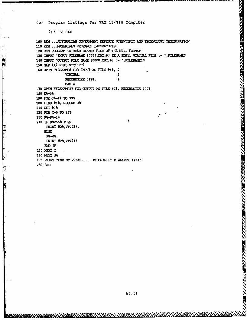
(b) Program listings for VAX 11/780 Computer
(1) V.BAS
100 REM ... AUSTRALIAN GOVE DEF SCIJIF='C AND TE CRGnfAICN
110 REM ... MTERILS RESEARCH I Rxaties'120 REM PROGRM TO READ BINARY FILE OF THE RT11 FOMAT130 INPUT "INPUT FIXWE C $.DAT;] IE A PDP11 VIRTAL FILE :- ",FnflE140 INPUT "OUTPUT FLE NA M $$$$.CXT;*] :- ",FILE$AM$
o150 MAP (A) REAL Vr2(127)160 OPU FILENAM F CR IPUT AS FILE 1%,
RECDSIZE 512%, &MAP A
170 OPEN F=01DlE2$ FR OTPUT AS FILE #2%, RECORDSIZE 132%180 K%-0%190 F R J%-1% TO 79%200 FnD #1%, RECCRD J%210 GET #1%220 FR I-0 TO 127230 Kb-K%-+l%240 IF K%<>5% TRW
PR.IT #2%,VT2(I),- ELSE
K%-0%
PRINT #2%,VT2(I)END IF
250 = I260 NEXT J%270 PRINT "END OF V.BAS ...... R BY D.WAUE 1984".280 END
Al1.11
LAI.II
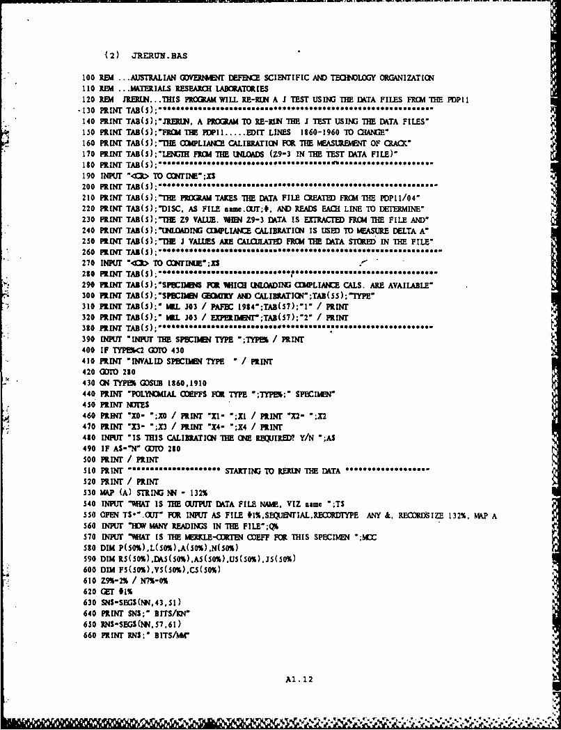
(2) JREAUTN. BAS
100 REM ... AUSTRALIAN GOVERNMET DEF SCIENTIFIC AM TEHNLOGY ORGANIZATICN110 REM ... MATERIALS RESEARCH LABORAOIES120 REM .IEUN... THIS PROGRAM WILL RE-RUN A J TEST USING THE ITA FILES FRCM THE PDPI 1
-130 PRINT TAB(S)**140 PRINT TAB(5);"JERUN. A PROGRAM TO RE-RLN THE J TEST USING THE ITA FILES-150 PRINT TAB(5);*FRCd THE PDPII ..... EDIT LINES 1860-1960 TO CHANE"160 PRINT TAB(5); TEE CCMPLIANCE CALIBRATICN FOR THE mEAsURBIENT OF CRACX"170 PRINT TAB();"Lucr FIo THE UNLOADS (Z9-3 IN THE TEST DATA FILE)-130 PRIN' TAB(S); " ****** ** *ge** **** ** *****6d** *S***** *** *** *** **
190 INPUT "(€1> TO CTIIE";XS200 PRINT TBS210 PRINT TAB(5);"TIE PRGRAM TAKES THE DATA FILE CREATED FRCM THE PDP1I/04"220 PRINT TAB(5);-DISC. AS FILE naa.OUT;#, AND READS EACH LINE TO DETERMINE"230 PRINT TAB(5);"TIIHE Z9 VALUE. WIN Z9-3 DATA IS EXTRACTED FR(C THE FILE AND-240 PRINT TAB(5);"ULOADING COPLIANCE CALIBRATION IS USED TO MEASURE DELTA A-250 PRINT TAB(5):;'THE J VALUES ARE CALCULATED FR( THE DATA STORED IN THE FILE"260 PRINT TAB(5A)B;(*******Ss***s*s*270 IW "UT > TO CONTINMJEXS280 PRINT TAB(S) ;290 PRINT TAB(S);*SPECIIIS Fm vImci UNLOADIm (hIMPLIAICE CALS. ARE AVAILABLE"300 PRINT TAB(S);"SPCIIum GorIIY AND CALIBIATIO;TAB(SS);-TYPE"310 PRINT TAB(5);" JUL J03 / PAFEC 1984";TAB(57);-'" / PRINT320 PRINT TAB(S);" ML J03 / E[PEIIENT';TAB(S7);'2" / PRINT380 PRINT TAB(S) * * * ** ***390 INPUT "INPUT THE SPl MThU TYPE ";TYPS / PRINT400 IF TYPOk2 a=T* 430410 PRINT "INVALID SPECRIJE TYPE - / PRINT420 TO 280430 ON TYPEI GOSUB 1860,1910440 PRINT "POLYNCMIAL (lEFFS FOR TYPE ";TYP ';" SPECIMEN"450 PRINT l17'Es460 PRIT "x0- ";X0 / PRINT "71- ";XI / PRINT "X2- ";X2470 PRINT "x3- ";X3 / PRINT "X4- ";X4 / PRINT480 INPUT "IS THIS CALIBRATION THE (NE REUIR.ED? Y/N ";AS490 IF AS-'N" GOT0 280500 PRINT / PRINT510 PRINT ********* STARTING TO RERUN THE DATA520 PRINT / PRINT530 MAP (A) STRING NN - 132%540 INPUT "YIAT IS THE UTPUT DATA FILE NAME, VIZ name ';T$550 OPEN T$*'.OUT" FOR INPUT AS FILE tl%,SELUENTIAL,RECORUFYPE ANY &, RECORDIIZE 132%. MAP A560 INPUT "W MANY READINGS IN THE FILE" ;QY570 INPUT "IHAT IS THE MERKLE-(fRTEN COEFF FOR THIS SPECIIEN ";MCI50 DIM P(S0%),L(C0%),A(S0%).N(S0%)590 DIM R5(50%),DA5(50%),A5(50%),U5(50%),J5(50%)600 DIM FS(50%).VS(50%).CS(S0%)610 Z9%-2% / N7%-O%620 WT #1%630 SNS-SEGS(NN,43.51)640 PRINT SNS;" BITS/UN"650 RNSSEGS(NN.57,61)660 PRINT RNS;" BITS/PA"
Al.12
L-.
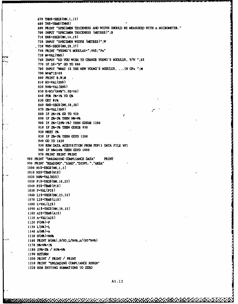
670 *1?HSES(Mt.1 .13)630 IS-manimS)690 pRINF SpECINNI THICp4ESS AND WIDTH SIUJW BE MEASURED WITH A MIaM4ETER.-700 INKl -SPECIhMI THIaJESS (METES)- ;B710 UNS-SECS(NN.14,19)720 INPUT 'SPBCDAEN WIDTHI (MEMRS ) W730 VYN-SEGS(Mi2,37)740 PRINT 'YOLNGS MaCUIAS-;VNS;'Pa
4,750 WVYAL(ThS)760 nour -W You WISH -ro amNE Yamt's mxuujUs. Y/N ';ss770 IF.SS-N' OD TO 800780 INPUK "MH& IS THE NEW YOUNG'S M3(X=LS IN GP& ';M790 M-I4'IE+09800 MRINIr B,W,M810 N3-VAL(SNS)a820 N4%-YAL (RNS)230 K.-N3/(N4V1 .0E-06)840 FOR 1%- 1% TO i
850 GET #1%860 SSEGS(1t.58.58)870 ZYIVAL(SNS)880 IF Z%-1% OD TO 920890 IF ZX-2% THHJ N16-0%900 IF ZY#-(Z9%-1%) IMfl GSUB 1200910 IF ZS-3% I GDSUB 950920 NEXT 1%930 IF ZX-3% THIN GDM 1200940 GO TO 1620950 REM DATA ACQUISITION PRCM PDPI1 DkTA FILE VFl960 IF N*<O% THI (DO 1000970 PRINK PRINT PRIN
980 PRINT 'UNLOADING C~1PLIANCE DAiTA' PlINr990 PRIN *READINGr,"LCAD .DISPL. - .AREA-
1000 NIS&SEGS(lNN.1,S)1010 N2S-rRM(N1S)1020 N6%-VAL(N2S)1030 P1S-SEGS(1M.10,23)1040 P2S-TRM(PIS)1050 P-VAL(P2S)1060 LIS-SGS(M,23,3S)1070 L2S-TRM(L1S)1080 L-VAL(L2S)1090 AIS-SEGS(NN.,38.53)1100 2S-TRMSA1S)1110 A-VAL(A2S)1120 P(Na)-P1130 L(l&)-L1140 A(N%)-A1150 N(N%)-N6%1160 PRINr N(NIA),P/N3,L/N4%.A/(N3*N4%)1170 N%-&+1%1180 Z9%-a6 / N5%-NY*1190 RETEMRN1200 PRINT / PRINT / PRINr1210 PRIN 'UNLOADIG CMPLIANCE RERUN"1220 REM SETrIN) STMM~TIWS TO ZERO
Al. 13
1230 El-0 / E2-0 / E3-0 / E4-0 / ES-0 / E6-01240 E7-0 / ES0 / E9-0 / E10-0 / P%01250 PRINT "kX. NO. OF UNLOADING POINTS IS ";N5%1260 INPUT M MANY OFF THE MAX. LOAD ARE TO BE DISCARDED ";OY*1270 IF (OI>(NS%-10%) THEN PRINT "ERROR IN INPUT. TRY AGAIN" / G1OT 12501280 IF 01*-0 THEN PR NT "DISCARD OF ZERO POINTS IS O? <Y/N> " / INPUT Zs / IF zs$eY" c Gm1290 FOR (3-(0%-(X) TO (N5%-I%) STEP *1%1300 El- EI*P(C%) / E2-E2 L(C() / E3-E3-P(( )L(CY)1310 E4"E4+L(C) 2% / E6-E6-P(CI) 21
1320 P%"F% 1%1330 NEXT (31340 REM CALCJLATXIC OF SLOPE1350 ES-E3-((EI*E2)/FI) / E9-E4-((E2 2%)/F )1360 ES-ES/E91370 RIM CALCULATIGN OF CORRELATION CDEF.
1380 E1O-E6-((EI 2%)/F%)
1390 E7-(ES 2)/(E9*EIO)1400 V-(K*MB)/E5 / REM MRMALIZED CIMPLIANCE1410 VS(N7%)-V / CS(N7%)-E71420 R X0*X1*+X2V 2%X3Y 3%+X4*V 4%1430 IF N7%>-1% GOIO 14501440 Y1-R*W / YO-Yl / GTO 1460 e1450 Yl-R*W1460 PINT "CHBC OF N OF UNLOADING POINTS ";Fl;" SHOULD BE ";N5%-.(X1470 PRINT "CACK LEH- ";Y1;" METRES"1480 P INT "READ11","'IDATA POINTS', "NORM. CCMPL. 'ORR. CEF. ',AREA, -AIW' -DELTA A-. J"1490 J-bCC'A(C1)/(B*(W-YI )*N3°N4%'1000)1500 U -N6%-NS%*1%1510 MRINT T%.P1.V,E7,A((3)/(N3sN4%),R.YI-YO.J1S20 Z9%- t1530 US(N7%)-UnL / As(N7%)-A(Ot)/(NY*Nr4) / R5(N7%)-R1540 IA.s(N7%)-Y1-Y0 / Js(N7%)-J / F5(N7%)-F%1550 INPUT "¢> TO PRCEED TO NEXT UNLOADING SET ";X$1560 N7%oN7%+ 1%1570 IF IQQ% THEN Gro 16101580 PRINT "LAST UNLOADIING DTA SET"1590 INPUT "SET PRINTER AND 4R FOR PRINT OUT OF UILOADING COMPLIANCE CALCS";X$
1600 GUO 16201610 RETURN1620 CLOSE #1%1630 PRINT / PRINT / PRINT1640 PRINT "SUMMRY OF UNLOADING COMPLIANCE CALCULATIONS"1650 PRINT "L USING JRERIN.BAS ON THE VAXII/790"1660 PRINT "USING PDPl1/04 DATA FILE ";T$;"(RUN THRUGIH V.BAS)"
1670 PRINT1680 PRINT "YUING'S MUJLUS FOR THESE CALCUATIONS ";M."Pa"1690 PRINT "SPECIMEN THICKNESS-";B;*metres"1700 PRINT "SPECIMEN WIDTH ";W;"metres" / PRINT
1710 PRINT NOITES1720 PRINT "POLYNOMIAL FIT CDEFFS"1730 PRINT "XO- ";XO;" X1- ";XI;" X2- ";X21740 PRINT "X3- ";X3;" X4- ";X4
1750 PRINT1760 PRINT MERKLE-CORTI (CODEFF- ";MCC1770 PRINT / PRINT1780 PRINT "READING.DATA POINTS-,"NORM CCMPL-,-CDRR CDEF. ,-AREA','A/W".-DELTA A" ,J VALUE
Al . 14

1790 FO N%-0% TO N7%-1%1300 PRINT US(Na),F5(N).Vs(N),C5(N%).A(N),R5(N%).A5s(N),J5(N1 )1810 NEXT NS1920 PRINT / PRINT1830 PRINT -HIS FILE WILL BE STORED AS ";TS;'.DAT'1840 PRINT 'RUN JPRINT TO RETRIEVE THIS FILE"
ItSO (DTO 21101860 REM CMLIANCE CALIBRATIONS (POLYMtIAL FITS)
1870 NDTES-"J03 CAL. FROM PAFEC 1984'1830 XO-7.4857727E-02 / XI-1.7894292E-02 / X2--2.3063905E-041390 X3-1.5006292E-06 / X4--3.7869343E-091900 RETURN1910 REM1920 NDnTES-J03 CAL. FROM CLARK EXPT. DAkTA-1930 XO-1.0697574E-01 I XI-1.4754694E-02 / X2--1.6242350E-041940 X3-8.7544527E-07 / X4--1.7795666E-091950 RETURN1960 R3M2110 REM PROGRAM TO INRITE A SENNIARY OF THE JRERI4 CALCJLATIONS AS A FILE name.DAT2120 OPEN T$*'.DA" FI R OUTPUT AS FILE #2%, ORGANIZATICN SEQENTIAL. RECQRDTYPE ANY2130 PRINT #2%, TS2140 PRINT #2,M2150 PRINT #,2%.B
2160 PRINT #2%.W2170 PRINT #2%.NjTES2180 PRINT #2%.xo / PRINT #2%,XI / PRINT #2%,X2 / PRINT #2%,X3 / PRINT #2%.X42190 PRINT *2%,ILM2200 1U-N7%-1%2210 PRINT #2%,R%2220 FOR N*-o% TO IM2230 PRINT ,2%.Us(N%)2240 PRINT *2%,FS(NI)2250 PRINT 42%.vS(Nl)2260 PRINT ,2%.C (Ni)2270 PRINT *2%,A(Nl%)
2280 PRINT *2%,RS(Nl)2290 PRINT #2%,tu (Nl)
2300 PRINT #2%,Js(Nl)2310 NEXT Nil
2320 CLOSE #2%2330 PRINT / PRINT2340 PRINT "END OF JIEUlN.BAS ........ program by D.S.Saunders and I.A.Butch 1985"2350 END
Al .15
• , +. ,• .. . . 'I , " ". • '+p ,€".," " "".," " "e ,,¢" Z~r ,P" ,!" " ' -,IS
(3) ACCESS1.BAS
RIEM ... AUSTRALIAN GVERNMENT DEFNCE SCIENTIFIC AND TEIQLOGY ORGINIZATION
110 REM ... MTERIALS RESEARCH LABORATORIES120 REM THIS PROGRAM WILL AaESS OUPUT FILES FOR TEST DATA FOR THE VAX 11/780
130 PRINT TAB() *
140 PRINT TAB(S) ;'ACCESS!. A PR(XORAM TO ONVERT A i INTEGRAL TEST DATA FILE*
150 PRINT TAB(5);'INTO A PLUITING DATA FILE FOR USE WITH THE KENNET PLOT ROUINE-
160 PRINT TAB(S)***.********************* OSSS* OS..9 ** *********
170 PRINT TAB(5);-THE PROGRAM TAKES THE DATA FILE CEATI) FRO I THE PDPI 1/04"
180 PRINT TAB(5);'DISK, AS FILE $$$.WUT;#, AND WRITES A NEW FILE (FORCE/DISPL.)"
190 PRINT TAB(5);-NAME THIS FILE SSSS.G A;#"
200 PRINT TAB(5);"THE PROGRAM WILL RECO)RD THE VAX DATA FILE FROM HIICH SSSS.GRA;# IS CREATED"
210 PRINT TAB(S); *** * *..e........* ******* ** * * * * OSS****SSSSSSSS'
220 MAP (A) STRING N - 132%
230 INPUT "WHAT IS THE OUTPUT FILE NAME, VIZ SSSS.0UW;#. ";TS
240 OPEN TS FOR INPUT AS FILE #1%,SEQUENfIALRE)RDTYPE ANY &,RECORDSIZE 132%. MAP A
250 INPUT HAT IS THE PLOTTING FILE NAME, VIZ SSSS.GRA;#. ";SS
260 OPEN SS FOR OUTPUT AS FILE #2%,ORGANIZATION SEQUENTIAL VARIABLE
270 INPUT "V-AT IS THE FIRST READING NUMBER YOY WANT TO ACCESS" ;P
280 INPUT "VHAT IS THE LAST READING NU IER YOU WANT TO ACCESS;Q
290 GET #1%300 SNS-SEGS(NN.43,51)
310 PRINT SNS
320 RNS-SEGS(N,57,61)
330 PRINT RNS
340 N3-VAL(SNS)
350 N4%-VAL%(RNS)
360 PRINT TAB(20) ;'SELFECTE FORCE/DISPLcwwr DATA FRWM';T$
370 PRINT TAB(20);'WRITTEN INTO PLOTTING FILE ";SS
380 PRINT TAB(20);*SCALING ONSTANTS FOR TIE TEST"
390 PRINT TAB(20);'FOR LOAD, RO- ";N3;TAB(50);"BITS/KN
400 PRINT TAB(20);"FOR DISPL, Rl- *;N4%;TAB(50);*BITS/?4A"
410 PRINT / PRINT
420 PRINT #2%.DISPLACEMENT IN MR4"
430 PRINT #2%.1%;*."
440 PRINT #2%.'FORCE IN KN
450 PRINT #2%,1%;*.-
460 US-LEFTS(TS.4)470 PRINT #2%,-DATA FROM ORIGINAL ON PDP1I/04 DISK. AS ";US;".DAT"
480 PRINT TAB(5);-READINGS NO ';P%;" TO ";Q%; "INCLUSIVE"
490 PRINT / PRINT
500 B%--((t-P%)-'i)510 PRINT #2%,B%520 PRINT *2%."PL7TINIG DATA FROM ";TS;"READING NOS ";P%;'IO ;Q%;' CL"
530 FOR 1% - 1% TO 2000%
540 GET #1%
550 NNWS-RIGf'S(NN. 7)
560 NIs-LEFT (Nl , 17)
570 N2S-SEGS(*M .18,33)
5S0 NI-VAL(NI$)
590 N2-VAL(N2S)
600 IF l%<P% THEN 640
610 IF I%>Q TIEN 650
Al .16
..4
620 PRINT N2/N4%.NI/N3630 PRINT #2%.N2/N4%;",;NI/N3
640 NEXT 1%.65 SCLOSE #1%/ CLOSE #2%660 PRINT "END OF ACCSSEAS..Program by D.S.Saunders"
*670 DI
Al . 17
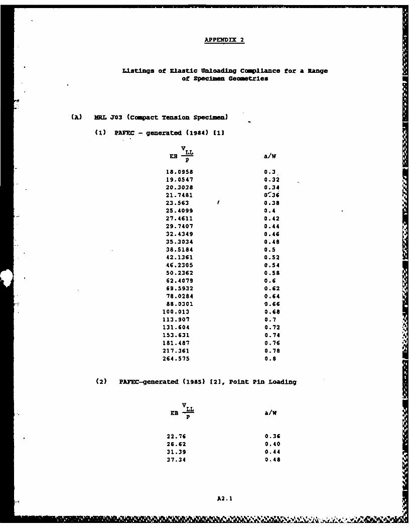
APPENDIX 2
Listings of Elastic Unloading Compliance f or a Rangeof Specimen Ge ome tries
(A) MRL J03 (Compact Tension Specin)
(1) PAinc- generated (1984) [1
U-VL a/WP
18.0958 0.319.0547 0.3220.3038 0.3421.7481 W-3623.563 0.3825.4099 0.427.4611 0.4229.7407 0.4432.4349 0.4635.3034 0.4838.5184 0.542.1361 0.5246.2305 0.5450.2362 0.5862.4079 0.669.5932 0.6278.0284 0.6488.0301 0.66
100.013 0.68113.907 0.7131.604 0.72153.631 0.74181.487 0.76217.361 0.78264.575 0.8
(2) PAFEC-generated (1985) 121, Point Pin Loading
V LLEB - a/W
P
22.76 0.3626.62 0.4031.39 0.4437.34 0.48
A2.1I
%- kk . .

44.74 0.5254.43 0.5667.30 0.6085.00 0.64
109.9 0.68147.5 0.72207.3 0.76
The second PAFEC-generated compliance calibration [2] is nowconsidered to be more accurated than (1), aboe. For this calibration theoriginal mesh was modified slightly and the normalised compliance data isclose to the experimental data given in (31 and reproduced below.
V_ VLL-EB a/W.P
24.78 0.37826.64 0 39329.58 0.41940.76 0.49341.6 0.49541.65 0.49740.58 0.49841.63 0.498
42.76 0.50744.5 0.51753.41 0.54455.15 0.56157.75 0.56559.43 0.56790.6 0.644
110.3 0.670154.0 0.722167.0 0.735209.0 0.763212.1 0.764215.9 0.767225.7 0.768224.9 0.773242.5 0.778251.9 0.784278.0 0.793
(B) ASTM E 399 (Compact Tension Specimen), [41,[51
VLL
EB -a/WP
8.6 0.211.18 0.2514.28 0.3018.09 0.35
A2.2
* U U I . . t P. . . .. o, o .. ... . u . %'%'
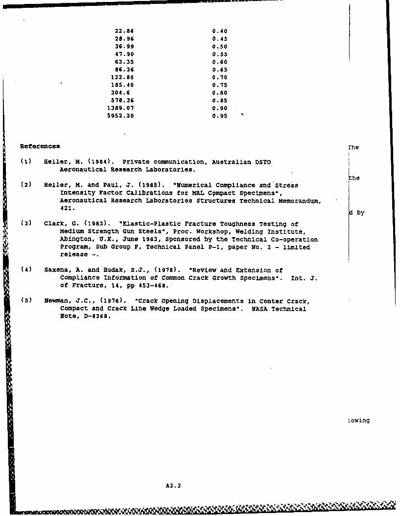
22.86 0.4028.96 0.4536.99 0.5047.90 0.5563.35 0.6086.36 0.65
122.80 0.70185.40 0.75304.6 0.80578.36 0.85
1389.07 0.905952.20 0.95
References rhe
(I) Heller, M. (1984). Private comunication, Australian DSTOAeronautical Research Laboratories.
"he(2) Heller, M. and Paul, J. (1985). "Numerical Compliance and stress
Intensity Factor Calibrations for MRL Cqmpact Specimens",Aeronautical Research Laboratories Structures Technical Memorandum,421. d by
(3) Clark, G. (1983). "Elastic-Plastic Fracture Toughness Testing ofMedium Strength Gun Steels", Proc. Workshop, Welding Institute,Abington, U.K., June 1983, Sponsored by the Technical Co-operationProgram, Sub Group P, Technical Panel P-I, paper No. 2 - limitedrelease -.
(4) Saxena, A. and Hudak, S.J., (1978). "Review and Extension ofCompliance Information of Common Crack Growth Specimens". Int. J.of Fracture, 14, pp 453-468.
(5) Newman, J.C., (1976). "Crack Opening Displacements in Center Crack,Compact and Crack Line Wedge Loaded Specimens". NASA TechnicalNote, D-8268.
Lowing
A2.3
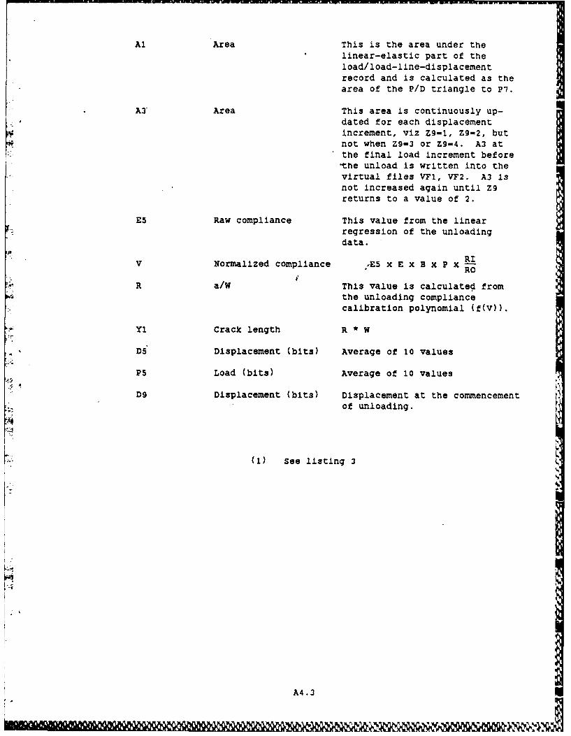
Al Area This is the area under thelinear-elastic part of theload/load-line-displacementrecord and is calculated as thearea of the P/D triangle to P7.
A3 Area This area is continuously up-dated for each displacementincrement, viz Z9-1, Z9-2, butnot when Z9-3 or Z9-4. A3 atthe final load increment beforethe unload is written into thevirtual files VFl, VF2. A3 isnot increased again until Z9returns to a value of 2.
E5 Raw compliance This value from the linearregression of the unloadingdata.
V Normalized compliance E5 x E x B x P x RIRO
R a/W This value is calculated fromthe unloading compliancecalibration polynomial (f(v)).
Yl Crack length R * W
D5 Displacement (bits) Average of 10 values
P5 Load (bits) Average of 10 values
D9 Displacement (bits) Displacement at the commencementof unloading.
(1) See listing 3
A4.3
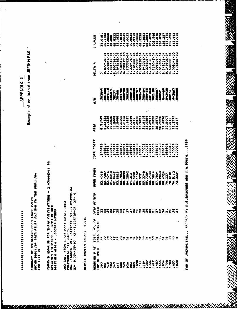
cc . OUn "OlUSOO00N 00000.000
z 1 - . 0n16101 1D lf~l 03 S.0-NC3l.
I4.4..mflUOWWWOU0..- -r
000 ~WO 00 0Ow0NN000 000I 1 1 11;1 ' ' h
CL 0 0 0 0 4.C n mI vW O C I N O N w0
0
o nMC 00- f00r0.00% 0
~N . v..! 4 .0..~nN 0 C -.41 044 v! 0 S 0 n 3! aWON Nf 0
000000000 a0 000000000000C0 Iw 3 !ol 1 f l ! W 0 0 00
w - caer- 0r e
00* 10
0.0
a..
U. 0cf. m 1
U. gumc0Q. 9N 0N0U. I" M M n N N N M 0 M 0
q z0 .ONOrO!.!!OC.. r - 0 3 ! r 4.%. 3 ! . 0 0 0 r - ! 0A0
M 19 r. U. a000 000r% 1%00 0 000N0 00 00 0
a . M0X ILL & c r- o-C
L* - . U 0 a0
0 .v a 4 r 4 0 0 - N I . f r N . 3 0 .
0. N 4. hi uz0 0
w Ww 4 ILX z l I-
.4v a
LZ CSA~u. -S CC
-.. pllllp qw -q w - 7w - -q w ww
M EE ..... * ~%fd