Embed Size (px)
Citation preview

J I B A N D G A N T R Y
CRANES

2
Work ing Harder For You
In 1876, Edwin Harrington dramatically improved the
self-sustaining hoist by introducing the worm-gear
design. Since then, the company he founded has
earned a proud reputation for product innovations
and consistent quality that our customers count
on to meet their diverse requirements.
Over the years, we have developed and grown by
recognizing the value of our customers and responding
to your needs. The daily mission of our organization
is to provide you, the customer, with the highest
quality in our products, service and support.
In addition to our superior products and expanded
facilities, we offer a Sales and Customer Service
team that is dedicated to serving you, a well qualified
Engineering Department to support your technical
needs and a full support staff who all know the
importance of working together to provide solutions
for your material handling projects.
We are working harder to be the supplier-of-choice
for all of your hoist and crane applications.

3
H A R R I N G T O N J I B A N D G A N T R Y C R A N E S
3
Tab le O f Contents
Motorized Jib Cranes . . . . . . . . . . . . . . . . . . . . . . . . . . . . . . . . . . . 4
Superior Load Positioning Control Packages . . . . . . . . . . . . . . 5
Free Standing Jib Cranes . . . . . . . . . . . . . . . . . . . . . . . . . . . . . . . 6
Wall Bracket Jib Cranes . . . . . . . . . . . . . . . . . . . . . . . . . . . . . . . . 8
Wall Cantilever Jib Cranes . . . . . . . . . . . . . . . . . . . . . . . . . . . . . .10
Mast Type Jib Cranes . . . . . . . . . . . . . . . . . . . . . . . . . . . . . . . . . . .12
Fixed Height Steel Gantry Cranes . . . . . . . . . . . . . . . . . . . . . . . .14
Adjustable Steel Gantry Cranes . . . . . . . . . . . . . . . . . . . . . . . . . .15
Foundation Information . . . . . . . . . . . . . . . . . . . . . . . . . . . . . . . . .16
Work Station Cranes . . . . . . . . . . . . . . . . . . . . . . . . . . . . . . . . . . . .18
Articulating Jib Cranes . . . . . . . . . . . . . . . . . . . . . . . . . . . . . . . . .18
Complete Product Offering . . . . . . . . . . . . . . . . . . . . . . . . . . . . . .19

4
Motorized Jibs are available in the Free Standing, Wall Cantilever, Wall Bracket, and Mast Type Series. Retrofit Motorized kits for Free Standing Jibs are also available.
Why a Motorized Jib Crane?
Motorized Jibs are not mere adaptations. They are totally conceived as motorized products, with all the outstanding features of standard jibs, plus these:
• Variable Frequency Drives (VFD) are standard on all Motorized Jib Cranes. The drive can be configured for single or multiple speeds.
• Precision drive assembly with field adjustable torque limiter for added drive protection.
• Worm gear reducer with oil bath lubrication for reliable operation and low maintenance. Worm gear reducer includes overload safety clutch.
• Totally enclosed, fan cooled, 3 phase Class B, 40°C ambient continuous, "C" faced motor, 30 minute rated, is standard.
• Direct drive for all series of jib cranes allows for accurate and consistent positioning of loads. This modular drive design makes maintenance easy and reduces long term costs.
• Wall Cantilever and Mast Type masts are boxed for extra rigidity to withstand the forces of a Motorized Crane and provide more precise load control.
FS300DD
MT400MD
WB100MD
WC200MD
Motor i zed J ib C ranes

5
H A R R I N G T O N J I B A N D G A N T R Y C R A N E S
Features of Motorized Control Package
• Variable Frequency Drive (VFD) is standard. The Variable Frequency Drive can be used in one, two, or three speed applications.
• Variable Frequency Drive provides the ultimate in load control. The VFD provides the ultimate in load control and positioning from the slowest possible creep speed up to maximum speed. The VFD is up to 25 times smoother than ballast resistor controls, does not produce extensive heat, and enables precise starting and stopping.
• Easily adjustable speed control.Through a simple keypad on the VFD, the acceleration rate, deceleration rate and rotation speed can be adjusted to fit your application. This allows you to customize the performance of the jib to your exact requirements.
• Designed for indoor and outdoor use.When being used outdoors, the cranes are designed to operate in winds of 15 mph or less, based on a maximum load surface of 64 square feet. Consult the factory for applications exceeding these standards.
• Standard NEMA Rated Control Enclosure.This standard control enclosure meets the requirements for NEMA 3R, 12, 4, and 4X environments. Optional enclosures are available for other environments.
• Low maintenance costs.The VFD eliminates the need for magnetic reversing contactors, reduces the number of wearable components in the panel, and reduces long-term maintenance costs.
Super io r Load Pos i t ion ing Cont ro l Packages
Retrofit Existing Jibs with Motorized Rotation
The Retrofit Traction Drive kit will fit all Free Standing Jibs with box-style head assemblies no matter who made your jib crane. The modular drive assembly bolts to the back of the box-style head assembly. The drive powers large, heavy-walled rollers. The drive roller is easily adjusted to ensure a constant driving force. This is a great way to upgrade an existing Free Standing Jib Crane with motorized power making the Retrofit Kit a great, cost-effective way to solve workers’ compensation or safety problems. Retrofit Traction Drive kits are available for indoor applications up to 5 Ton with spans to 20 feet.
This Retrofit Motorized FS300 Free Standing Jib Crane gives operators the control needed to quickly and precisely position loads.
The direct drive powers the rotation of the Free Standing Crane. A speed of 1/2 RPM is standard.
Variable Speed Controls provide the ultimate in jib crane rotation control from creep speed to maximum speed.

6
Our Advantage
Ease of Operation
• Allows operators to position loads precisely, effortlessly and efficiently.
• Precision tapered roller bearings in top pivot and trunnion assemblies provide smooth operation and long life.
• Full supporting triangular base plate gussets are used (in lieu of struts) to minimize crane deflection, thus making it easier to accurately position loads.
Ease of Installation
• Independent head assembly installed separately from the boom for easier installation.
• Recessed bearing assembly allows greatly reduced clearances needed for installation.
• Bolted head/boom connection which permits separate installation and provides maximum lift for the hoist, since it can be installed very close to the underside of the lower ceiling obstruction for greater headroom.
• Movable bolted trolley stops.
• In-head totally enclosed, bottom entry collector assembly allows the option of easily adding power to the hoist for 360° rotation at the time of or after purchase.
Safety
• Head retaining pin provides the resistance to accidental upward dislodgement of the head.
• Pre-engineered for use with powered hoists. A factor of 15% of the jib crane capacity is allowed for the hoist and trolley weight with an additional 25% of the capacity allowed for impact, thus, giving maximum capacity use of the jib.
Power Rotation
• Is optional
Free Stand ing J ib C ranes
Maximum Versatility and Performance
Our most versatile crane. Perfect for underneath large bridge cranes, in open areas where it can serve several work stations, in outdoor applications such as loading docks, or in machining and assembly operations where it can be overlapped with other jibs to provide staged operation.
8" 12" 14" 16" 18" 20" 24" 30"
6 6 6 12 12 12 12 12
1" 1.25" 1.25" 1.25" 1.25" 1.25" 1.25" 1.25"
24" 24" 30" 36" 42" 48" 54" 60"
Mast Diameter E
Number of Anchor Bolts
Bolt Diameter (D)
Bolt Circle* (Q)
Note: For jib crane foundation requirements, overturning moment, axial load and anchor bolt pull out forces, consult Customer Service.
*Note: Dimensions from corners of the hexagonal baseplate are 6" longer than the corresponding bolt circle.
FS350 INSERT MOUNTED
FS300 BASEPLATE MOUNTED
FS350 INSERT SLEEVE
MOUNTED
†
†Refer to page 16 and 17 for foundation information.

7
Model Number ExplanationExample: 1/4 Ton FS300-8-6: 1/4 Ton = 500 pound capacity, FS300 = base plate mount style,8 = mast diameter in inches (E), 6 = boom depth in inches (W). Use "E" dimension to determine base plate and anchor bolt dimensions.
Other Models, Sizes and CapacitiesFS350 (insert mounted), FS350S (sleeve insert mounted), and other spans, heights, and capacities are available by contacting Customer Service.
Dimensions are subject to change without notice.
SPAN A/Model Number*
Capacity Dim B 8' 10' 12' 14' 16' 18' 20'
1/4 TON 8' FS300-8-6 FS300-8-6 FS300-8-6 FS300-12-8 FS300-12-8 FS300-12-10 FS300-12-10
10' FS300-8-6 FS300-8-6 FS300-8-6 FS300-12-8 FS300-12-8 FS300-12-10 FS300-12-10
12' FS300-8-6 FS300-8-6 FS300-12-6 FS300-12-8 FS300-12-8 FS300-12-10 FS300-12-10
14' FS300-8-6 FS300-8-6 FS300-12-6 FS300-12-8 FS300-12-8 FS300-12-10 FS300-14-10
16' FS300-8-6 FS300-8-6 FS300-12-6 FS300-12-8 FS300-12-8 FS300-12-10 FS300-14-10
18' FS300-8-6 FS300-12-6 FS300-12-6 FS300-12-8 FS300-14-8 FS300-14-10 FS300-14-10
20' FS300-8-6 FS300-12-6 FS300-12-6 FS300-14-8 FS300-14-8 FS300-14-10 FS300-16-10
1/2 TON 8' FS300-8-6 FS300-8-6 FS300-12-7 FS300-12-8 FS300-12-10 FS300-12-10 FS300-12-12
10' FS300-8-6 FS300-8-6 FS300-12-7 FS300-12-8 FS300-12-10 FS300-12-10 FS300-14-12
12' FS300-8-6 FS300-12-6 FS300-12-7 FS300-12-12 FS300-12-12 FS300-14-16 FS300-14-16
14' FS300-8-6 FS300-12-6 FS300-12-10 FS300-12-12 FS300-12-12 FS300-14-16 FS300-14-16
16' FS300-8-6 FS300-12-6 FS300-12-10 FS300-12-12 FS300-14-12 FS300-14-16 FS300-16-16
18' FS300-8-6 FS300-12-6 FS300-12-10 FS300-14-12 FS300-14-12 FS300-16-16 FS300-16-16
20' FS300-8-6 FS300-12-6 FS300-14-10 FS300-14-12 FS300-14-12 FS300-16-16 FS300-16-16
1 TON 8' FS300-12-7 FS300-12-8 FS300-12-10 FS300-14-12 FS300-14-12 FS300-14-16 FS300-14-16
10' FS300-12-7 FS300-12-8 FS300-12-10 FS300-14-12 FS300-14-12 FS300-14-16 FS300-14-16
12' FS300-12-7 FS300-12-8 FS300-14-10 FS300-14-12 FS300-16-12 FS300-16-16 FS300-16-16
14' FS300-12-7 FS300-12-8 FS300-14-10 FS300-14-12 FS300-16-12 FS300-18-16 FS300-18-16
16' FS300-12-7 FS300-12-8 FS300-14-10 FS300-16-12 FS300-18-12 FS300-18-16 FS300-18-16
18' FS300-12-7 FS300-14-8 FS300-16-10 FS300-16-12 FS300-18-12 FS300-18-16 FS300-18-16
20' FS300-12-7 FS300-14-8 FS300-16-10 FS300-18-12 FS300-18-12 FS300-20-16 FS300-20-16
2 TON 8' FS300-14-10 FS300-14-12 FS300-16-12 FS300-16-16 FS300-16-18 FS300-18-18 FS300-18-18
10' FS300-14-10 FS300-14-12 FS300-16-12 FS300-16-16 FS300-16-18 FS300-18-18 FS300-18-18
12' FS300-14-10 FS300-14-12 FS300-16-12 FS300-16-16 FS300-16-18 FS300-18-18 FS300-18-18
14' FS300-14-10 FS300-14-12 FS300-16-12 FS300-16-16 FS300-18-18 FS300-18-18 FS300-20-18
16' FS300-14-10 FS300-14-12 FS300-16-12 FS300-18-16 FS300-18-18 FS300-18-18 FS300-24-18
18' FS300-14-10 FS300-16-12 FS300-18-12 FS300-18-16 FS300-20-18 FS300-20-18 FS300-24-18
20' FS300-14-10 FS300-16-12 FS300-18-12 FS300-18-16 FS300-20-18 FS300-20-18 FS300-24-18
3 TON 8' FS300-16-12 FS300-16-16 FS300-18-16 FS300-18-18 FS300-20-18 FS300-20-21 FS300-24-24
10' FS300-16-12 FS300-16-16 FS300-18-16 FS300-18-18 FS300-20-18 FS300-20-21 FS300-24-24
12' FS300-16-12 FS300-16-16 FS300-18-16 FS300-18-18 FS300-20-18 FS300-20-21 FS300-24-24
14' FS300-16-12 FS300-16-16 FS300-18-16 FS300-18-18 FS300-20-18 FS300-20-21 FS300-24-24
16' FS300-16-12 FS300-16-16 FS300-18-16 FS300-18-18 FS300-20-18 FS300-24-21 FS300-24-24
18' FS300-16-12 FS300-16-16 FS300-18-16 FS300-20-18 FS300-24-18 FS300-24-21 FS300-24-24
20' FS300-16-12 FS300-16-16 FS300-20-16 FS300-20-18 FS300-24-18 FS300-24-21 FS300-24-24
5 TON 8' FS300-18-16 FS300-20-18 FS300-24-18 FS300-24-21 FS300-24-24 FS300-30-24 FS300-30-24
10' FS300-18-16 FS300-20-18 FS300-24-18 FS300-24-21 FS300-24-24 FS300-30-24 FS300-30-24
12' FS300-18-16 FS300-20-18 FS300-24-18 FS300-24-21 FS300-24-24 FS300-30-24 FS300-30-24
14' FS300-18-16 FS300-20-18 FS300-24-18 FS300-24-21 FS300-24-24 FS300-30-24 FS300-30-24
16' FS300-18-16 FS300-20-18 FS300-24-18 FS300-24-21 FS300-24-24 FS300-30-24 FS300-30-24
18' FS300-18-16 FS300-20-18 FS300-24-18 FS300-24-21 FS300-24-24 FS300-30-24 FS300-30-24
20' FS300-18-16 FS300-20-18 FS300-24-18 FS300-24-21 FS300-24-24 FS300-30-24 FS300-30-24
FS30 0 BasePlate Mounted
Free Stand ing J ib C ranes
*Specify Capacity and Span with Model Number
8
Wal l B racket J ib C ranes
The Economical Solution
The Wall Bracket (WB100) Jib is the most economical means of providing hoist coverage for individual use in bays, along walls or columns of plants, or as a supplement to an overhead crane or monorail system.
Two key requirements must be met before applying the Wall Bracket Series:
1) A structurally adequate wall or column to support the jib must exist.
2) Sufficient clearance above the boom throughout its arc to accommodate the tie rod suspension must exist.
Our Advantage
Ease of Movement
• Low dead weight of the boom combined with bronze bushings and oil-impregnated bronze thrust washers provide for easy rotation and superior load positioning.
Safety
• Formed bracket fittings provide for greater reliability. No welds in tension, all bolts are in double shear.
• Pre-engineered for use with powered hoists. A factor of 15% of the jib crane capacity is allowed for the hoist and trolley weight with an additional 25% of the capacity allowed for impact, thus giving maximum capacity use of the jib.
Ease of Installation
• Single tie rod, right hand threaded at both ends for easy boom adjustment and installation.
• All connections bolted, including movable bolted trolley stops.
• Grease fittings are provided for easy field lubrication.
200° Power Rotation
• Is optional
The Thrust & Pull diagram above details the thrust and pull forces that the jib applies to the supporting structure when a load is lifted. It is essential that a structurally adequate wall or column exists. Refer to the Thrust & Pull chart opposite this page for exact forces.
Fitting kits are available for fabrication of cranes locally.
TOP BRACKET FITTING
BOTTOM BRACKET FITTING
WB100 WALL BRACKET
Fitting kits are available for fabrication of cranes locally.
BEAM BRACKET FITTING

9
WB10 0 Wal l B racket
Capacity Span A Model Tie Rod Thrust & Number* B D E F G W Diameter Pull
1/2 TON 8' WB100-G1-8-6 2' 9" 1' 3" 13 1/2" 3 1/2" 3 1/2" 6" 1" 3709#
10' WB100-G1-10-6 3' 0" 1' 6" 13 1/2" 3 1/2" 3 1/2" 6" 1" 4408#
12' WB100-G1-12-6 3' 9" 1' 9" 13 1/2" 3 1/2" 3 1/2" 6" 1" 4347#
14' WB100-G1-14-6 4' 6" 2' 0" 13 1/2" 3 1/2" 3 1/2" 6" 1" 4317#
16' WB100-G1-16-6 5' 6" 2' 0" 13 1/2" 3 1/2" 3 1/2" 6" 1" 4109#
18' WB100-G1-18-7 6' 0" 2' 0" 13 1/2" 3 1/2" 3 1/2" 7" 1" 4380#
20' WB100-G1-20-8 6' 6" 2' 3" 13 1/2" 3 1/2" 3 1/2" 8" 1" 4658#
24' WB100-G1-24-8c6 7' 6" 2' 6" 13 1/2" 3 1/2" 3 1/2" 8" 1" 5350#
30' WB100-G1-30-12c8 10' 0" 3' 6" 13 1/2" 3 1/2" 3 1/2" 12" 1" 6009#
1 TON 8' WB100-G1-8-6 2' 9" 1' 3" 13 1/2" 3 1/2" 3 1/2" 6" 1" 7273#
10' WB100-G1-10-6 3' 0" 1' 6" 13 1/2" 3 1/2" 3 1/2" 6" 1" 8608#
12' WB100-G1-12-6 3' 9" 1' 9" 13 1/2" 3 1/2" 3 1/2" 6" 1" 8453#
14' WB100-G1-14-7 4' 6" 2' 0" 13 1/2" 3 1/2" 3 1/2" 7" 1" 8422#
16' WB100-G1-16-7 5' 6" 2' 3" 13 1/2" 3 1/2" 3 1/2" 7" 1" 7992#
18' WB100-G1-18-8 6' 0" 2' 6" 13 1/2" 3 1/2" 3 1/2" 8" 1" 8430#
20' WB100-G1-20-10 6' 6" 2' 6" 13 1/2" 3 1/2" 3 1/2" 10" 1" 8966#
24' WB100-G1-24-10c8 7' 6" 2' 9" 13 1/2" 3 1/2" 3 1/2" 10" 1" 9877#
30' WB100-G1-30-12c8 10' 0" 3' 6" 13 1/2" 3 1/2" 3 1/2" 12" 1" 10069#
2 TON 8' WB100-G2-8-8 2' 9" 1' 3" 13 1/2" 4" 4 1/8" 8" 1 1/2" 14469#
10' WB100-G2-10-8 3' 0" 1' 6" 13 1/2" 4" 4 1/8" 8" 1 1/2" 17107#
12' WB100-G2-12-8 3' 9" 1' 9" 13 1/2" 4" 4 1/8" 8" 1 1/2" 16780#
14' WB100-G2-14-8 4' 6" 2' 0" 13 1/2" 4" 4 1/8" 8" 1 1/2" 16578#
16' WB100-G2-16-10 5' 6" 2' 3" 13 1/2" 4" 4 1/8" 10" 1 1/2" 15864#
18' WB100-G2-18-10 6' 0" 2' 3" 13 1/2" 4" 4 1/8" 10" 1 1/2" 16552#
20' WB100-G2-20-12 6' 6" 2' 6" 13 1/2" 4" 4 1/8" 12" 1 1/2" 17348#
24' WB100-G2-24-12c8 7' 6" 3' 0" 13 1/2" 4" 4 1/8" 12" 1 1/2" 18836#
30' WB100-G2-30-12c8 10' 0" 3' 0" 13 1/2" 4" 4 1/8" 12" 1 1/2" 18189#
3 TON 8' WB100-G3-8-8 2' 9" 1' 3" 14" 4" 4 5/8" 8" 1 1/2" 21596#
10' WB100-G3-10-8 3' 3" 1' 6" 14" 4" 4 5/8" 8" 1 1/2" 23545#
12' WB100-G3-12-10 4' 0" 1' 9" 14" 4" 4 5/8" 10" 1 1/2" 23557#
14' WB100-G3-14-10 4' 9" 2' 0" 14" 4" 4 5/8" 10" 1 1/2" 23514#
16' WB100-G3-16-10 5' 6" 2' 3" 14" 4" 4 5/8" 10" 1 1/2" 23500#
18' WB100-G3-18-12 6' 3" 2' 3" 14" 4" 4 5/8" 12" 1 1/2" 23672#
20' WB100-G3-20-12c8 7' 0" 2' 6" 14" 4" 4 5/8" 12" 1 1/2" 24037#
24' WB100-G3-24-12c8 8' 6" 3' 0" 14" 4" 4 5/8" 12" 1 1/2" 24197#
30' WB100-G3-30-12c8 11' 0" 3' 0" 14" 4" 4 5/8" 12" 1 1/2" 23917#
5 TON 8' WB100-G5-8-12 3' 0" 1' 6" 15 1/4" 6" 7" 12" 2" 33006#
10' WB100-G5-10-12 3' 3" 1' 6" 15 1/4" 6" 7" 12" 2" 39258#
12' WB100-G5-12-12 4' 0" 1' 9" 15 1/4" 6" 7" 12" 2" 39072#
14' WB100-G5-14-12 4' 9" 2' 0" 15 1/4" 6" 7" 12" 2" 38972#
16' WB100-G5-16-16 5' 6" 2' 6" 15 1/4" 6" 7" 16" 2" 39229#
18' WB100-G5-18-16 6' 3" 3' 0" 15 1/4" 6" 7" 16" 2" 39246#
20' WB100-G5-20-16c12 7' 0" 3' 6" 15 1/4" 6" 7" 16" 2" 39877#
24' WB100-G5-24-16c12 8' 6" 3' 6" 15 1/4" 6" 7" 16" 2" 40708#
30' WB100-G5-30-16c12 11' 0" 3' 6" 15 1/4" 6" 7" 16" 2" 39597#
Model Number Explanation: Example: 3 Ton WB100-G3-20-12c8: 3 Ton = 6,000 pound capacity, WB100 = wall bracket style, 20 = span (A),12 = boom depth in inches (W), c8 = 8" cap channel welded to top of boom.
Other Sizes & CapacitiesOther spans and capacities are available by contacting Customer Service. Dimensions are subject to change without notice.
*Specify Capacity and Span with Model Number

10
Wal l Cant i lever J ib C ranes
For Maximum Lift:
The Wall Cantilever (WC200) provides hoist coverage and 200° rotation for individual use in bays, along walls or columns of plants, or as a supplement to an overhead crane or monorail system. This jib has the advantage of providing maximum lift for the hoist, since it can be installed very close to the underside of the lowest ceiling obstruction.
Two key requirements must be met before applying the Wall Cantilever Series:
1) A structurally adequate wall or column to support the jib must exist.
2) Sufficient clearance above the boom throughout its arc must exist.
Our Advantage
Ease of Movement
• The fittings contain bronze bushings and oil-impregnated bronze thrust washers which provide for easy rotation and superior load positioning.
Safety
• Fabricated steel fittings provide excellent torsional rigidity.
• Pre-engineered for use with powered hoists. A factor of 15% of the jib crane capacity is allowed for the hoist and trolley weight with an additional 25% of the capacity allowed for impact, thus giving maximum capacity use of the jib.
Ease of Installation
• When the bracket center dimension is 6' 0" or less, the mast/boom connection is welded. This provides the most economical means of installation.
• When the bracket center is greater than 6' 0", a bolted mast/boom connection is used, which enables the larger cranes to be shipped disassembled for ease of handling during shipping and installation.
• Grease fittings are provided for easy field lubrication.
200° Power Rotation• Is optional
The diagram above details the thrust and pull forces that the jib crane applies to the supporting structure when a load is lifted. It is essential that a structurally adequate wall or column exists to support the jib crane. Refer to the Thrust & Pull chart opposite this page for exact forces.
WC200 WALL CANTILEVER
TOP AND BOTTOM BRACKET FITTINGS
B1, B2, and B3 fitting kits are available for fabrication of cranes locally.
11
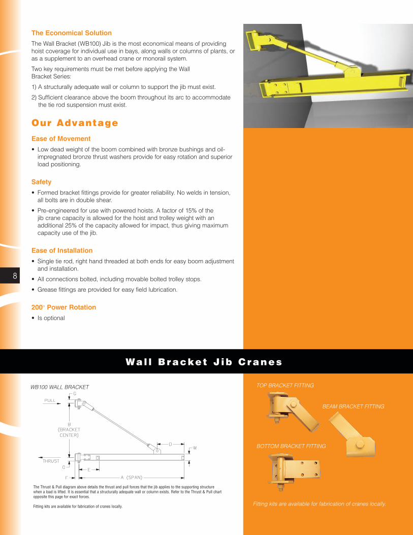
Capacity A Span Model Number* B E F G W Thrust and Pull
1/4 TON 8' WC200-B1-8-6 3' 0" 5" 3 1/2" 6" 6" 1767#
10' WC200-B1-10-6 3' 0" 5" 3 1/2" 6" 6" 2308#
12' WC200-B1-12-6 3' 0" 5" 3 1/2" 6" 6" 2867#
14' WC200-B1-14-7 3' 0" 5" 3 1/2" 6" 7" 3533#
16' WC200-B1-16-8 3' 0" 5" 3 1/2" 6" 8" 4285#
18' WC200-B1-18-8 4' 0" 5" 3 1/2" 6" 8" 3720#
20' WC200-B1-20-10 4' 0" 5" 3 1/2" 6" 10" 4595#
1/2 TON 8' WC200-B1-8-7 3' 0" 5" 3 1/2" 6" 7" 3430#
10' WC200-B1-10-7 3' 0" 5" 3 1/2" 6" 7" 4455#
12' WC200-B1-12-7 3' 0" 5" 3 1/2" 6" 7" 5501#
14' WC200-B1-14-8 4' 0" 5" 3 1/2" 6" 8" 5001#
16' WC200-B1-16-10 4' 0" 5" 3 1/2" 6" 10" 6063#
18' WC200-B1-18-10 4' 0" 5" 3 1/2" 6" 10" 6979#
20' WC200-B1-20-12 6' 0" 5" 3 1/2" 6" 12" 5493#
1 Ton 8' WC200-B1-8-8 4' 0" 5" 3 1/2" 6" 8" 5047#
10' WC200-B1-10-10 5' 0" 5" 3 1/2" 6" 10" 5294#
12' WC200-B1-12-10 5' 0" 5" 3 1/2" 6" 10" 6526#
14' WC200-B1-14-10 5' 0" 5" 3 1/2" 6" 10" 7778#
16' WC200-B1-16-12 6' 0" 5" 3 1/2" 6" 12" 7678#
18' WC200-B1-18-16 6' 0" 5" 3 1/2" 6" 16" 9148#
20' WC200-B1-20-16 6' 0" 5" 3 1/2" 6" 16" 10367#
2 TON 8' WC200-B2-8-12 4' 0" 5" 4" 6" 12" 10054#
10' WC200-B2-10-12 4' 0" 5" 4" 6" 12" 12998#
12' WC200-B2-12-16 4' 6" 5" 4" 6" 16" 14409#
14' WC200-B2-14-16 5' 0" 5" 4" 6" 16" 15442#
16' WC200-B2-16-18 6' 0" 5" 4" 6" 18" 15067#
18' WC200-B2-18-18 6' 6" 5" 4" 6" 18" 15892#
20' WC200-B2-20-20 7' 6" 5" 4" 6" 21" 15840#
3 TON 8' WC200-B3-8-16 4' 0" 5" 4" 6" 16" 15060#
10' WC200-B3-10-16 4' 6" 5" 4" 6" 16" 17300#
12' WC200-B3-12-16 5' 6" 5" 4" 6" 16" 17389#
14' WC200-B3-14-18 6' 0" 5" 4" 6" 18" 19017#
16' WC200-B3-16-18 7' 6" 5" 4" 6" 18" 17653#
18' WC200-B3-18-20 8' 6" 5" 4" 6" 21" 17982#
20' WC200-B3-20-24 9' 6" 5" 4" 6" 21" 18105#
5 TON 8' WC200-B5-8-18 6' 6" 7" 6" 9" 18" 15323#
10' WC200-B5-10-18 6' 6" 7" 6" 9" 18" 19770#
12' WC200-B5-12-20 6' 6" 7" 6" 9" 21" 24379#
14' WC200-B5-14-20 7' 6" 7" 6" 9" 21" 25077#
16' WC200-B5-16-24 9' 6" 7" 6" 9" 21" 22941#
18' WC200-B5-18-24 9' 6" 7" 6" 9" 24" 26485#
20' WC200-B5-20-24 9' 6" 7" 6" 9" 24" 29769#
WC2 0 0 Wal l Cant i lever
Model Number Explanation:Example : 1 Ton WC200-B1-12-10: 1 Ton = 2,000 pound capacity, WC200 = wall cantilever style, 12 = span (A), 10 = boom depth in inches (W).
Other Sizes and CapacitiesOther spans and capacities are available by contacting Customer Service.
Dimensions are subject to change without notice.
*Specify Capacity and Span with Model Number

12
The Economical 360° solution
The MT Series Crane is floor supported, top stabilized, and is capable of 360° rotation via a top and bottom bearing assembly.
Three key requirements must be met before deciding on a Mast Type Jib Crane:
1. An adequate structural support to stabilize the crane at the top of the mast must exist. If the jib is installed underneath an overhead crane runway or building truss, then the deflection of the supporting member may not exceed 1/2 inch.
2. Clearance overhead for the pivot assembly must exist.
3. Clearance overhead for the boom to rotate must exist.
Available in Two Styles
1) MT400 Full Cantilever—provides for maximum amount of lift where full use of available headroom is desired.
2) MT450 Drop Cantilever—jib boom can be placed at a specific height to clear overhead obstructions.
Our Advantage
Economical
• Simple, efficient design that usually requires no special foundation makes the Mast Type Cranes the most cost effective of the 360° rotation jib styles.
Exerts Less Force on Building Structure
• Exerts the least amount of force of any jib on its supporting structure.
Safety
• Utilizes a self-aligning radial bushing at the top which cannot be displaced, and an identical self-aligning radial bushing at the bottom which, used in combination with an oil-impregnated bronze thrust washer, provides ease of movement.
• Pre-engineered for use with powered hoists. A factor of 15% of the jib crane capacity is allowed for the hoist and trolley weight with an additional 25% of the capacity allowed for impact, thus giving maximum capacity use of the jib.
Productive
• Allows full utilization of the working area with 360° rotation.
Maximum Trolley Travel
• Mast/beam connections eliminate the need for tie rods or knee braces found on competitive designs, thus permitting maximum trolley travel.
Power Rotation
• Is optionalThe diagram above details the thrust and pull forces that the jib crane applies to the supporting structure when a load is lifted. It is essential that a structurally adequate wall or column exists to support the jib crane. Contact Customer Service for specific thrust and pull forces.
MT450 DROP CANTILEVER
MT400 FULL CANTILEVER
Mast Type J ib C ranes

13
SPAN A/Model Number*
Capacity Dim C 8' 10' 12' 14' 16' 18' 20'
1/4 TON 10' MT400-8-6-15 MT400-8-6-15 MT400-8-7-15 MT400-8-8-15 MT400-8-8-15 MT400-10-10-15 MT400-10-10-15
12' MT400-8-6-15 MT400-8-6-15 MT400-8-7-15 MT400-8-8-15 MT400-8-8-15 MT400-10-10-15 MT400-10-10-15
14' MT400-8-6-15 MT400-8-6-15 MT400-8-7-15 MT400-8-8-15 MT400-10-8-15 MT400-10-10-15 MT400-10-10-15
16' MT400-8-6-15 MT400-8-6-15 MT400-8-7-15 MT400-8-8-15 MT400-10-8-15 MT400-10-10-15 MT400-10-10-15
18' MT400-8-6-15 MT400-8-6-15 MT400-8-7-15 MT400-8-8-15 MT400-10-8-15 MT400-10-10-15 MT400-10-10-15
20' MT400-8-6-15 MT400-8-6-15 MT400-8-7-15 MT400-10-8-15 MT400-10-8-15 MT400-10-10-15 MT400-14-10-15
1/2 TON 10' MT400-8-6-15 MT400-10-7-15 MT400-10-8-15 MT400-14-10-15 MT400-14-10-15 MT400-14-12-15 MT400-14-12-15
12' MT400-8-6-15 MT400-10-7-15 MT400-10-8-15 MT400-14-10-15 MT400-14-10-15 MT400-14-12-15 MT400-14-12-15
14' MT400-8-6-15 MT400-10-7-15 MT400-10-8-15 MT400-14-10-15 MT400-14-10-15 MT400-14-12-15 MT400-14-12-15
16' MT400-8-6-15 MT400-10-7-15 MT400-10-8-15 MT400-14-10-15 MT400-14-10-15 MT400-14-12-15 MT400-14-12-15
18' MT400-8-6-15 MT400-10-7-15 MT400-10-8-15 MT400-14-10-15 MT400-14-10-15 MT400-14-12-15 MT400-14-12-15
20' MT400-10-6-15 MT400-10-7-15 MT400-10-8-15 MT400-14-10-15 MT400-14-10-15 MT400-14-12-15 MT400-16-12-15
1 TON 10' MT400-10-8-15 MT400-14-10-15 MT400-14-10-15 MT400-14-12-15 MT400-14-12-15 MT400-16-16-20 MT400-16-16-20
12' MT400-10-8-15 MT400-14-10-15 MT400-14-10-15 MT400-14-12-15 MT400-14-12-15 MT400-16-16-15 MT400-16-16-20
14' MT400-10-8-15 MT400-14-10-15 MT400-14-10-15 MT400-14-12-15 MT400-14-12-15 MT400-16-16-15 MT400-16-16-15
16' MT400-10-8-15 MT400-14-10-15 MT400-14-10-15 MT400-14-12-15 MT400-16-12-15 MT400-16-16-15 MT400-18-16-15
18' MT400-14-8-15 MT400-14-10-15 MT400-14-10-15 MT400-16-12-15 MT400-16-12-15 MT400-18-16-15 MT400-18-16-15
20' MT400-14-8-15 MT400-14-10-15 MT400-14-10-15 MT400-16-12-15 MT400-16-12-15 MT400-18-16-15 MT400-18-16-15
2 TON 10' MT400-14-10-15 MT400-14-12-20 MT400-16-16-20 MT400-16-16-20 MT400-18-18-20 MT400-18-18-25 MT400-21-21-25
12' MT400-14-10-15 MT400-14-12-20 MT400-16-16-20 MT400-16-16-20 MT400-18-18-20 MT400-18-18-20 MT400-21-21-20
14' MT400-14-10-15 MT400-16-12-15 MT400-16-16-20 MT400-18-16-20 MT400-18-18-20 MT400-18-18-20 MT400-21-21-20
16' MT400-14-10-15 MT400-16-12-15 MT400-18-16-15 MT400-18-16-20 MT400-18-18-20 MT400-18-18-20 MT400-21-21-20
18' MT400-16-10-15 MT400-16-12-15 MT400-18-16-15 MT400-18-16-15 MT400-18-18-20 MT400-21-18-20 MT400-21-21-20
20' MT400-16-10-15 MT400-18-12-15 MT400-18-16-15 MT400-18-16-15 MT400-18-18-15 MT400-21-18-20 MT400-21-21-20
3 TON 10' MT400-16-12-20 MT400-16-16-20 MT400-18-16-20 MT400-18-18-25 MT400-21-20-25 MT400-21-21-25 MT400-21-24-25
12' MT400-16-12-20 MT400-16-16-20 MT400-18-16-20 MT400-18-18-25 MT400-21-20-25 MT400-21-21-25 MT400-21-24-25
14' MT400-16-12-20 MT400-18-16-20 MT400-18-16-20 MT400-18-18-20 MT400-21-20-25 MT400-21-21-25 MT400-21-24-25
16' MT400-18-12-15 MT400-18-16-20 MT400-18-16-20 MT400-18-18-20 MT400-21-20-20 MT400-21-21-25 MT400-24-24-25
18' MT400-18-12-15 MT400-18-16-15 MT400-18-16-20 MT400-21-18-20 MT400-21-20-20 MT400-24-21-20 MT400-24-24-25
20' MT400-18-12-15 MT400-18-16-15 MT400-18-16-20 MT400-21-18-20 MT400-21-20-20 MT400-24-21-20 MT400-24-24-25
5 TON 10' MT400-18-18-25 MT400-18-18-25 MT400-21-21-25 MT400-21-21-25 MT400-24-24-25 MT400-24-24-25 MT400-24-24-25
12' MT400-18-18-25 MT400-18-18-25 MT400-21-21-25 MT400-21-21-25 MT400-24-24-25 MT400-24-24-25 MT400-24-24-25
14' MT400-18-18-20 MT400-18-18-25 MT400-21-21-25 MT400-21-21-25 MT400-24-24-25 MT400-24-24-25 MT400-27-24-25
16' MT400-18-18-20 MT400-21-18-20 MT400-21-21-25 MT400-24-21-25 MT400-24-24-25 MT400-27-24-25 MT400-27-24-25
18' MT400-18-18-20 MT400-21-18-20 MT400-24-21-20 MT400-24-21-25 MT400-27-24-25 MT400-27-24-25 MT400-27-24-25
20' MT400-21-18-20 MT400-21-18-20 MT400-24-21-20 MT400-24-21-25 MT400-27-24-25 MT400-27-24-25 MT400-27-24-25
MT40 0 Mast Type Cranes
Model Number ExplanationExample: 1/2 Ton MT400-8-6-15: 1/2 Ton =1000 pound capacity, MT400 = full cantilever style, 8 = mast wide flange depth in inches (E), 6 = boom depth in inches (W), 15 = mast pivot pin diameter (1.5").
Other Models, Sizes and CapacitiesMT450 (drop cantilever) and other spans, heights, and capacities are available by contacting Customer Service.
Dimensions are subject to change without notice.
*Specify Capacity and Span with Model Number

14
Fixed Height Stee l Gant r y C ranes
The Mobile Solution
Fixed Height Steel Gantry Cranes provide an economical way to lift materials anywhere in a facility. The heavy duty end frame design with square tubing uprights, knee braces and channel base provides stable lifting and movement.
Our Advantage
Ease of Movement
• The non-marking, durable polyurethane casters provide low rolling resistance for easy movement. The polyurethane wheel rolls smoothly, even over rough floor surfaces, and can withstand water, oil and most other chemicals.
Safety
• Bolted beam to upright connection to ensure that beam does not dislodge.
• Pre-engineered for use with powered hoists. A factor of 15% of the crane capacity is allowed for the hoist and trolley weight with an additional 25% of the capacity allowed for impact, thus giving maximum capacity use of the crane.
All Gantry Cranes shown above: Tread (E) dimension is 78" between caster pivot centers. Polyurethane 6" diameter steel casters are standard.
Model Number Explanation: Example: FG-1-12-8: FG = fixed gantry crane, 1 = 1 Ton (2,000 pound) capacity, 12 = height under beam (B) in feet, 8 = overall span (A) in feet. Specifications subject to change without notice. Available in capacities to 5 Ton and spans to 30 feet. Special capacities, heights, casters and spans are available. Price on request.
A Model B C D W Capacity Span Number HUB OAH Clear I-Beam Span Depth
FG-1-10-8 10' 10' 6" 6' 11-1/4" 6" 8' FG-1-12-8 12' 12' 6" 6' 11-1/4" 6" FG-1-15-8 15' 15' 6" 6' 10-1/4" 6" FG-1-10-10 10' 10' 6" 8' 11-1/4" 6" 10' FG-1-12-10 12' 12' 6" 8' 11-1/4" 6" FG-1-15-10 15' 15' 6" 8' 10-1/4" 6" FG-1-10-12 10' 10' 6" 10' 11-1/4" 6" 12' FG-1-12-12 12' 12' 6" 10' 11-1/4" 6"1 TON FG-1-15-12 15' 15' 6" 10' 10-1/4" 6" FG-1-10-15 10' 10' 7" 13' 11-1/4" 7" 15' FG-1-12-15 12' 12' 7" 13' 11-1/4" 7" FG-1-15-15 15' 15' 7" 13' 10-1/4" 7" FG-1-10-20 10' 10' 10" 18' 11-1/4" 10" 20' FG-1-12-20 12' 12' 10" 18' 11-1/4" 10" FG-1-15-20 15' 15' 10" 18' 10-1/4" 10" FG-1-10-25 10' 11' 0" 23' 9-1/4" 12" 25' FG-1-12-25 12' 13' 0" 23' 9-1/4" 12" FG-1-15-25 15' 16' 0" 23' 8-1/4" 12" FG-2-10-8 10' 10' 8" 6' 10-1/4" 8" 8' FG-2-12-8 12' 12' 8" 6' 10-1/4" 8" FG-2-15-8 15' 15' 8" 6' 9-1/4" 8" FG-2-10-10 10' 10' 8" 8' 10-1/4" 8" 10' FG-2-12-10 12' 12' 8" 8' 10-1/4" 8" FG-2-15-10 15' 15' 8" 8' 9-1/4" 8" FG-2-10-12 10' 10' 8" 10' 10-1/4" 8" 12' FG-2-12-12 12' 12' 8" 10' 10-1/4" 8"2 TON FG-2-15-12 15' 15' 8" 10' 9-1/4" 8" FG-2-10-15 10' 10' 10" 13' 10-1/4" 10" 15' FG-2-12-15 12' 12' 10" 13' 10-1/4" 10" FG-2-15-15 15' 15' 10" 13' 9-1/4" 10" FG-2-10-20 10' 11' 0" 18' 8-1/4" 12" 20' FG-2-12-20 12' 13' 0" 18' 8-1/4" 12" FG-2-15-20 15' 16' 0" 18' 7-1/4" 12" FG-2-10-25 10' 11' 3" 23' 8-1/4" 16" 25' FG-2-12-25 12' 13' 3" 23' 8-1/4" 16" FG-2-15-25 15' 16' 3" 23' 7-1/4" 16" FG-3-10-8 10' 10' 10" 6' 7-1/4" 10" 8' FG-3-12-8 12' 12' 10" 6' 7-1/4" 10" FG-3-15-8 15' 15' 10" 6' 7-1/4" 10" FG-3-10-10 10' 10' 10" 8' 7-1/4" 10" 10' FG-3-12-10 12' 12' 10" 8' 7-1/4" 10" FG-3-15-10 15' 15' 10" 8' 7-1/4" 10" FG-3-10-12 10' 10' 10" 10' 7-1/4" 10" 12' FG-3-12-12 12' 12' 10" 10' 7-1/4" 10"3 TON FG-3-15-12 15' 15' 10" 10' 7-1/4" 10" FG-3-10-15 10' 11' 0" 13' 7-1/4" 12" 15' FG-3-12-15 12' 13' 0" 13' 7-1/4" 12" FG-3-15-15 15' 16' 0" 13' 7-1/4" 12" FG-3-10-20 10' 11' 3" 18' 7-1/4" 16" 20' FG-3-12-20 12' 13' 3" 18' 7-1/4" 16" FG-3-15-20 15' 16' 3" 18' 7-1/4" 16" FG-3-10-25 10' 11' 6" 23' 6" 18" 25' FG-3-12-25 12' 13' 6" 23' 6" 18" FG-3-15-25 15' 16' 6" 23' 6" 18"

15
Ad justab le Stee l Gant r y C ranes
Ease of Installation
• All bolted connections between the beam and uprights.
Options
• Four position swivel locking casters.
• V-groove casters for track mounted cranes.
• Steel casters.
• Casters with wheel brakes.
• V-groove track.
The Flexible Solution
Adjustable Steel Gantry Cranes provide the most flexible lifting solution of any style jib crane. The adjustable Gantry can be moved to almost any location and can be easily adjusted to provide different lifting heights.
A Model B C D W Capacity Span Number HUB Oah Clear I-Beam Min/max Min/max Span Depth
AG-1-7/10-8 7' to 10' 7' 6" to 10' 6" 6' 10-5/8" 6" 8' AG-1-10/12-8 10' to 12' 10' 6" to 12' 6" 6' 10-5/8" 6" AG-1-12/15-8 12' to 15' 12' 6" to 15' 6" 6' 9-5/8" 6" AG-1-7/10-10 7' to 10' 7' 6" to 10' 6" 8' 10-5/8" 6" 10' AG-1-10/12-10 10' to 12' 10' 6" to 12' 6" 8' 10-5/8" 6" AG-1-12/15-10 12' to 15' 12' 6" to 15' 6" 8' 9-5/8" 6" AG-1-7/10-12 7' to 10' 7' 6" to 10' 6" 10' 10-5/8" 6" 1 TON 12' AG-1-10/12-12 10' to 12' 10' 6" to 12' 6" 10' 10-5/8" 6" AG-1-12/15-12 12' to 15' 12' 6" to 15' 6" 10' 9-5/8" 6" AG-1-7/10-15 7' to 10' 7' 7" to 10' 7" 13' 10-5/8" 7" 15' AG-1-10/12-15 10' to 12' 10' 7" to 12' 7" 13' 10-5/8" 7" AG-1-12/15-15 12' to 15' 12' 7" to 15' 7" 13' 9-5/8" 7" AG-1-7/10-20 7' to 10' 7' 10" to 10' 10" 18' 10-5/8" 10" 20' AG-1-10/12-20 10' to 12' 10' 10" to 12' 10" 18' 10-5/8" 10" AG-1-12/15-20 12' to 15' 12' 10" to 15' 10" 18' 9-5/8" 10" AG-1-7/10-25 7' to 10' 8' 0" to 11' 0" 23' 8-5/8" 12" 25' AG-1-10/12-25 10' to 12' 11' 0" to 13' 0" 23' 8-5/8" 12" AG-1-12/15-25 12' to 15' 13' 0" to 16' 0" 23' 7-5/8" 12" AG-2-7/10-8 7' to 10' 7' 8" to 10' 8" 6' 9-5/8" 8" 8' AG-2-10/12-8 10' to 12' 10' 8" to 12' 8" 6' 9-5/8" 8" AG-2-12/15-8 12' to 15' 12' 8" to 15' 8" 6' 8-5/8" 8" AG-2-7/10-10 7' to 10' 7' 8" to 10' 8" 8' 9-5/8" 8" 10' AG-2-10/12-10 10' to 12' 10' 8" to 12' 8" 8' 9-5/8" 8" AG-2-12/15-10 12' to 15' 12' 8" to 15' 8" 8' 8-5/8" 8" AG-2-7/10-12 7' to 10' 7' 8" to 10' 8" 10' 9-5/8" 8" 2 TON 12' AG-2-10/12-12 10' to 12' 10' 8" to 12' 8" 10' 9-5/8" 8" AG-2-12/15-12 12' to 15' 12' 8" to 15' 8" 10' 8-5/8" 8" AG-2-7/10-15 7' to 10' 7' 10" to 10' 10" 13' 9-5/8" 10" 15' AG-2-10/12-15 10' to 12' 10' 10" to 12' 10" 13' 9-5/8" 10" AG-2-12/15-15 12' to 15' 12' 10" to 15' 10" 13' 8-5/8" 10" AG-2-7/10-20 7' to 10' 8' 0" to 11' 0" 18' 7-5/8" 12" 20' AG-2-10/12-20 10' to 12' 11' 0" to 13' 0" 18' 7-5/8" 12" AG-2-12/15-20 12' to 15' 13' 0" to 16' 0" 18' 6-5/8" 12" AG-2-7/10-25 7' to 10' 8' 3" to 11' 3" 23' 7-5/8" 16" 25' AG-2-10/12-25 10' to 12' 11' 3" to 13' 3" 23' 7-5/8" 16" AG-2-12/15-25 12' to 15' 13' 3" to 16' 3" 23' 6-5/8" 16" AG-3-7/10-8 7' to 10' 7' 10" to 10' 10" 6' 6-5/8" 10" 8' AG-3-10/12-8 10' to 12' 10' 10" to 12' 10" 6' 6-5/8" 10" AG-3-12/15-8 12' to 15' 12' 10" to 15' 10" 6' 6-1/2" 10" AG-3-7/10-10 7' to 10' 7' 10" to 10' 10" 8' 6-5/8" 10" 10' AG-3-10/12-10 10' to 12' 10' 10" to 12' 10" 8' 6-5/8" 10" AG-3-12/15-10 12' to 15' 12' 10" to 15' 10" 8' 6-1/2" 10" AG-3-7/10-12 7' to 10' 7' 10" to 10' 10" 10' 6-5/8" 10" 3 TON 12' AG-3-10/12-12 10' to 12' 10' 10" to 12' 10" 10' 6-5/8" 10" AG-3-12/15-12 12' to 15' 12' 10" to 15' 10" 10' 6-1/2" 10" AG-3-7/10-15 7' to 10' 8' 0" to 11' 0" 13' 6-5/8" 12" 15' AG-3-10/12-15 10' to 12' 11' 0" to 13' 0" 13' 6-5/8" 12" AG-3-12/15-15 12' to 15' 13' 0" to 16' 0" 13' 6-1/2" 12" AG-3-7/10-20 7' to 10' 8' 3" to 11' 3" 18' 6-5/8" 16" 20' AG-3-10/12-20 10' to 12' 11' 3" to 13' 3" 18' 6-5/8" 16" AG-3-12/15-20 12' to 15' 13' 3" to 16' 3" 18' 6-1/2" 16" AG-3-7/10-25 7' to 10' 8' 6" to 11' 6" 23' 5-3/8" 18" 25' AG-3-10/12-25 10' to 12' 11' 6" to 13' 6" 23' 5-3/8" 18" AG-3-12/15-25 12' to 15' 13' 6" to 16' 6" 23' 5-1/4" 18"
All Gantry Cranes shown above: Tread (E) dimension is 78" between caster pivot centers. Polyurethane 6" diameter steel casters are standard.
Model Number Explanation:Example: AG-1-12/15-20; AG = Adjustable Gantry Crane, 1 = 1 Ton (2,000 pound) capacity, 12/15 = min/max height under beam (B) in feet, 20 = overall span (A) in feet. Specifications subject to change without notice. Available in capacities to 5 Ton and spans to 30 feet. Special capacities, heights, casters and spans are available. Price on request.

16
Foundat ion In fo rmat ion
FS300 Free Standing BasePlate Mounted(For other foundation information, consult Customer Service)
M
3/4 L
G1
E
H1
2 1/2"
SPAN
JK
H2
1" GROUT
L
REINFORCING RODS5/8" TOP, 3/4" BOTTOMON 12" CENTERS
2"-3"
2"-3"
G2 6" MIN.
12 BOLT
M
Q
M
Q
4"
2"
6 BOLT D(DIA OF BOLT)
60 60
FS300
BASE BOLT PATTERN

17
H A R R I N G T O N J I B A N D G A N T R Y C R A N E S
FS300 Free Standing BasePlate Mounted
CRANE DIMENSIONS
PIPE SIZE DIMENSIONS (IN.) ANCHOR BOLT PATTERN
E G1 G2 J K H1 H2 Qty D Q
8 10 20 10-3/8 10 46-3/4 4 6 1.00 24
12 8-1/2 20 12-7/8 12-1/2 71-3/4 6 6 1.25 24
14 11 22 15-3/8 15 72 8 6 1.25 30
16 13 26 17-3/8 17 72 8 12 1.25 36
18 15 30 17-3/8 17 72 9 12 1.25 42
20 17 34 17-3/8 17-1/2 72 10 12 1.25 48
24 18 36 22-7/8 22-1/2 77 12 12 1.25 54
30 18 36 25-3/8 25 84 12 12 1.25 60
FOUNDATION DEPTH
STANDARD FOOTING REQUIREMENTS
Capacity (Tons)
Span (ft.)
Width (ft.)M
Depth (ft.)L
1/48-13 4 3
14-20 4 4
1/28-12 4 4
13-20 5 4
1
8-10 5 4
11-15 6 4
16-20 7 4
1-1/2
8-12 6 4
13-15 7 4
16-20 8 4
2
8-11 6 4
12-15 7 4
16-20 8 4
38-16 8 4
17-20 9 4
48-13 8 4
14-20 10 4
5
8-14 9 4
15-18 10 4
19-20 10 5
Options
• BasePlate template
• Anchor bolts
(These items may be shipped in advance of crane order upon request.)
Refer to quotation and drawing for specific foundation information.

18
AJ360-F
WSJ360
WSJ360 Free Standing Work Station Jib Cranes
360° rotation
In most cases, WSJ360 Free Standing Series Jib Cranes can be bolted directly to your existing floor without adding special foundations. These cranes feature a retaining pin through the pivot pin to help resist accidental upward dislodgment of the boom assembly. Capacities up to 1,000 lbs.
WSJ200 Wall Cantilever Work Station Jib Cranes
200° rotation
The wall or column mounted WSJ200 crane uses tapered roller bearings at the pivot points for unsurpassed ease of rotation. To ensure that the jib is aligned through the pivot axis and thus avoid unwanted drifting of the boom, shim stock up to 7/32” is included with each jib. Capacities up to 1,000 lbs.
AL100 Wall Bracket Work Station Jib Cranes
200° rotation
The AL100 Wall Bracket Work Station Jib Crane utilizes a lightweight, high-strength extruded aluminum enclosed track for its boom. This revolutionary new aluminum track reduces the rotational dead weight of the boom by 56% to 68%, allowing the AL100 to rotate up to 40% easier than a comparable I-beam jib. Sufficient clearance throughout the arc of the boom must exist to accommodate the tie rod suspension. Capacities up to 2,000 lbs.
AJ360-F Free Standing Articulating Jib Cranes
The AJ360-F is perfect for applications that demand the use of an articulating jib, but there are no walls or columns to mount the crane. This crane offers effortless rotation and a consistent responsiveness when positioning loads in a work cell, through open doorways, or into machines. The base price includes the jib boom, jib arm, friction brakes, the clevis assembly for hook mounted lifting devices, and the free standing mast assembly (anchor bolts by others). Special foundations may be required. Capacities up to 2,000 lbs.
AJ360-C Ceiling Mounted Articulating Jib Cranes
The AJ360-C is mounted overhead leaving nothing to disrupt workflow in the production area below. The AJ360-C can be stationary mounted or platform supported from a Work Station Dual Girder Bridge Crane which allows usage outside the normal coverage of a bridge crane or the jib to swing under obstructions. With the jib mounted to a platform, multiple work cells can be covered with just one crane and lifting device. Included in the base price are the jib boom, jib arm, friction brakes, the clevis assembly for hook mounted lifting devices, and the assembly for ceiling mounting (anchor bolts by others). Capacities up to 2,000 lbs.
AJ200 Wall/Column Mounted Articulating Jib Cranes
The AJ200 is perfect for applications that require maneuvering under obstructions or around obstacles, and there is an adequate wall/column to support the crane. The base price includes the jib boom, jib arm, friction brakes, the clevis assembly for hook mounted lifting devices, and the mounting brackets (mounting hardware by others). Capacities up to 2,000 lbs.
Work Stat ion J ib C ranes
Ar t icu lat ing J ib C ranes
Contact Customer Service for dimensional and technical information, including: foundation requirements, thrust and pull requirements, weights, hardware and hoist requirements.

19
H A R R I N G T O N J I B A N D G A N T R Y C R A N E S
Com plete Product O f fe r ing
Over the years, Harrington has continued to respond to the needs of our customers by further expanding our product offerings. In addition to the many models described in this catalog, our full series of product catalogs, as shown below, will provide you with all of the information you will need to answer questions, specify a product and place an order. For catalog copies or answers to specific product questions, please contact our Customer Service Department by calling 800-233-3010 (Manheim, PA) or 800-317-7111 (Corona, CA) or e-mail [email protected]
Electric Wire Rope Hoists CatalogRefer to this Harrington catalog for detailed information on the following:• Deck/base mounted or lug suspended hoists • Standard headroom trolley hoists • Ultra-low headroom trolley hoists
Air Powered Hoists CatalogRefer to this Harrington catalog for detailed information on the following:• Compact Mini-Cat with pendant, cord and manipulator controls• Air hoists with pendant and cord controls• Air trolleys
Manual Hoist Products CatalogRefer to this Harrington catalog for detailed information on the following:• Lever hoists • Hand chain hoists • Hoist and trolley combinations
• Low headroom trolley hoists • Push and geared trolleys • Hoist load testers
Electric Chain Hoists CatalogRefer to this Harrington catalog for detailed information on the following: • Three phase electric chain hoists and trolleys• Single phase electric chain hoists and trolleys• Ergonomic electric chain hoists
Complete Cranes CatalogRefer to this Harrington catalog for detailed information on the following:• Heavy-duty Class C single girder top running and underhung cranes• Heavy-duty Class C double girder top running and underhung cranes• Medium-duty top running and underhung push cranes • Crane control panels
Crane Components CatalogRefer to this Harrington catalog for detailed information on the following:• End trucks-top running-motorized, geared and push• End trucks-underhung-motorized, geared and push• Double girder MAX-E-Lift end trucks• Convertible push end trucks• Beam accessory kits

CONTACT YOUR NEARBY HARRINGTON DISTRIBUTOR
Harrington Hoists, Inc.—Western Division 2341 Pomona Rd., No. 103, Corona, CA 92880-6973
951-279-7100 / 800-317-7111Fax: 951-279-7500
Harrington Hoists, Inc. 401 West End Ave., Manheim, PA 17545
717-665-2000 / 800-233-3010Fax: 717-665-2861
Warranty
All products sold by Harrington Hoists, Inc. are warranted to be free from defects in material and workmanship from date of shipment by Harrington for the following periods:
Manual Hoists & Trolleys — 2 yearsNER/ER Enhanced Features Models — 3 yearsNER/ER, SNER and ED Electric Hoists, Air Hoists & Trolleys, Crane Components — 1 yearSpare/Replacement Parts — 1 yearNER/ER “The Guardian” Electromagnetic Smart Technology Brake — 10 years
The product must be used in accordance with manufacturer’s recommendations and must not have been subject to abuse, lack of maintenance, misuse, negligence, or unauthorized repairs or alterations.
Should any defect in material or workmanship occur during the above time period in any product, as determined by Harrington Hoists’ inspection of the product, Harrington Hoists, Inc. agrees, at its discretion, either to replace (not including installation) or repair the part or product free of charge and deliver said item F.O.B. Harrington Hoists, Inc. place of business to customer.
Customer must obtain a Return Goods Authorization as directed by Harrington or Harrington’s published repair center prior to shipping product for warranty evaluation. An explanation of the complaint must accompany the product. Product must be returned freight prepaid. Upon repair, the product will be covered for the remainder of the original warranty period. If it is determined there is no defect, or that the defect resulted from causes not within the scope of Harrington’s warranty, the customer will be responsible for the costs of returning the product.
Harrington Hoists, Inc. disclaims any and all other warranties of any kind expressed or implied as to the product’s merchantability or fitness for a particular application. Harrington will not be liable for death, injury to persons or property, or for incidental, contingent, special or consequential damages, loss or expense arising in connection with the use or inability whatever, regardless of whether damage, loss, or expense results from any act or failure to act by Harrington, whether negligent or willful, or from any other reason.
Rev 2 Copyright © 2006 09-10 Specifications and dimensions areItem No. C-JGC subject to change without notice.
www.harringtonhoists.com