Embed Size (px)
Citation preview

8/3/2019 J. C. Slater- The Theory of Symmetryical Waveguide T's
http://slidepdf.com/reader/full/j-c-slater-the-theory-of-symmetryical-waveguide-ts 1/20
!Document oom, lil N ROOM 36-41a
i so rch La'bor2tory of E'1ctronjoS
Massachusetts Institute of eehnology
Cambridge 39, assachusetts2sa~~h1~2set~.nttV r iB D I
THE THEORY OF
SYMMETRICAL WAVEGUIDE T'S
J. C. SLATER
TECHNICAL REPORT NO. 37
APRIL 3, 1947
RESEARCH LABORATORY OF ELECTRONICS
MASSACHUSETTS INSTITUTE OF TECHNOLOGY
I
, 1
le
~~~t~~"I-
$-11%.
Lo-tl

8/3/2019 J. C. Slater- The Theory of Symmetryical Waveguide T's
http://slidepdf.com/reader/full/j-c-slater-the-theory-of-symmetryical-waveguide-ts 2/20
The research reported in this document was made possible
through support extended the Massachusetts Institute of Tech-
nology, Research Laboratory of Electronics, jointly by the Army
Signal Corps, the Navy Department (Office of Naval Research),
and the Army Air Forces (Air Materiel Command), under the
Signal Corps Contract No. W-36-039 sc-32037.
·- -- -I -I

8/3/2019 J. C. Slater- The Theory of Symmetryical Waveguide T's
http://slidepdf.com/reader/full/j-c-slater-the-theory-of-symmetryical-waveguide-ts 3/20
MASSACHUSETTS INSTITUTE OF TECHNOLOGY
Research Laboratory of Electronics
Technical Report No. 37 April 3, 1947
TEE THEORY OF SYMMETRICAL WAVEGUIDE T 'S
by
J. C. Slater
Abstract
A unified treatment, based on symmetry properties of solutions
of MaxwellIs equations, is given for the following problems: a waveguidecontaining an arbitrary reactive iris, a waveguide or coaxial T, and a
so-called "magic T". In each case, it is shown how by proper choice of
reference planes the transformer properties of the T can be expressed insimple form. The properties of so-called matched T s" are given as
special cases of the general non-matched T. Formulas are given for flow
of power, as well as for relations between input and output admittance orimpedance. In each case, there are certain undetermined parameters, which
could be determined by much more detailed analysis or by simple experiment.
The necessary experiments, and methods of experimentally realizing the
matched Tis, are described.
_ __I

8/3/2019 J. C. Slater- The Theory of Symmetryical Waveguide T's
http://slidepdf.com/reader/full/j-c-slater-the-theory-of-symmetryical-waveguide-ts 4/20__

8/3/2019 J. C. Slater- The Theory of Symmetryical Waveguide T's
http://slidepdf.com/reader/full/j-c-slater-the-theory-of-symmetryical-waveguide-ts 5/20
THE THEORY OF SY]fETRICAL WAVEGUIDE TIS
Several types of microwave cavities containing a number of waveguide outputs
have planes of symmetry, and their theory can be treated by simple methods. We shall
consider in the present paper six types of structure: the waveguide shunted by an iris,
the E-plane and H-plane TIs, the coaxial-to-waveguide junction, the coaxial T, and the
so-called magic T, shown in Fig. 1 a-f. We shall consider the problem of the relations
between impedances and power flow across the various outputs of these systems, regarding
(a) as a four-terminal network, (b)-(s) as six-terminal networks, and (f) as an eight-
terminal network. We shall use the symmetry properties of solutions of Maxwellis equa-
tions in deriving our results, and shall express the results in terms of a small number
of parameters, which could be determined theoretically from an exact solution of
Maxwell's equations, or which may be regarded as parameters in equivalent circuits for
thp various systems, which can be determined by appropriate experiments. Our general
method will be to set up certain standing-wave solutions of Maxwells equations, and to
express the general solution as a linear combination of these independent standing waves.
Similar methods of discussion were used by Schwinger, Kyhl, Dicke, Pound, and others in
the Radiation Laboratory, but since their results are not available in the literature it
seems worthwhile to give a unified presentation of the problems. The writer is indebted
to W. Bostick, E. Everhart, and A. F. Kip, Jr.. for discussions regarding the subject.
1. Behavior of Solutions in the Outouts. Each of the devices considered is a cavity,
with certain outpUts. If we solve MaxwellIs equations inside the cavity, for the fre-
quency at which we are operating, we shall find an infinite variety of solutions, pro-
vided we do not specify the boundary conditions at the outputs. If we consider only
those solutions in which there is real propagation (rather than attenuation) in at least
some output, we shall find that we can write all such solutions as linear combinations
of a finite number of solutions, which can be classified according to their symmetry with
respect to the plane of symmetry of the system. Thus in case (a) there will be two
standing-wave solutions, in one of which E is symnetric, in the other antisymmetric, in
the plane of the iris; by combination of these cosine-like and sine-like standirg waves
with arbitrary phase and amplitude, we can build up a superposition of traveling waves
in both directions, with arbitrary phases and amplitudes. Similarly in cases (b)-(e) we
shall find three independent solutions, and in (f) four such solutions.
Each of these solutions will have complicated behavior in the central part of
the cavity, which we shall not consider except as to its summetry. As we go cut in the
wavregulde or coaxial output, however, the field, which can be written as a superposition
of all norral modes of the guide , becomes simplified by the attenuation of all those
modes which are not propagated. We shall assume that the frequency is such that only the
-1-
1. J. C. Slater, Rev. Moo&. Phys., 18, 441 (1946), Chapter II.

8/3/2019 J. C. Slater- The Theory of Symmetryical Waveguide T's
http://slidepdf.com/reader/full/j-c-slater-the-theory-of-symmetryical-waveguide-ts 6/20
y
y
(I) (2) (I) (2)
(a) THE WAVEGUIDE SHUNTED
BY AN IRIS.
(b) THE E- PLANE T.
z
yy
Ai z
(3)
(I) (2)
S.
(c) THE H-PLANE T.
1(3)
(d) THE COAXIAL- TO-WAVE-GUIDE JUNCTION.
z
K-.)
z._ Y
x
(I)) (
(e) THE COAXIAL T.
2)
(f) THE MAGIC
· z-t
z
(I)
(3)
T.
Fi ure 1
-a-
-

8/3/2019 J. C. Slater- The Theory of Symmetryical Waveguide T's
http://slidepdf.com/reader/full/j-c-slater-the-theory-of-symmetryical-waveguide-ts 7/20
dominant mode is propagated in the output guides; thus at some distance the field reduces
to this dominant mode, and can be characterized entirely by two constants, a phase and an
amplitude, or a current and a voltage. We consider two types of output: a rectangular
guide, with dimensions a, b (afb), propagating only the dominant TE mode, or a coaxial
line, of radii rl, r2 (r2>rl), propagating only its principal mode.
For the rectangular guide, we may write the tangential components of field in
the form
y = ,/ sin Zx eJWt V(z)
(1)
-H - sin Be ejWt i(z).x ab a
Here V(z) and i(z) take the place of voltage and current,respectively. The ratio
-Ey/Hx = V/i may be treated as the impedance of the line. If we define Z as the value
of -y/H x for a pure traveling wave in the z direction, given by
Z - , here oo = X 2= W'0 0
and where
=i~#+ ' Xc = 2a,° c g
then the ratio of impedance to characteristic impedance, which we shall denote by Z,
and its reciprocal by Y, is given by Z = 1/Y = (V/i)/Zo. The origin in (1) is chosen to
be at one corner of the cross section of the guide. The constants are so chosen that
the power flow down the guide, which by general principles is the integral over the cross
section of Re ( x H) is equal to Re (VI). or a traveling wave aong the z
direction, of unit current amplitude, we have
V( + i(z) = e 2z/X ).
(2)0
Thus for a pure traveling wave of unit current amplitude, the ratio of impedance to
characteristic impedance is +1, the sign depending on the direction of flow, and the
average power flow is + ZO. By superposing traveling waves in opposite directions,
we can set up standing waves. Thus we can build up symmetric and antisymmetric func-
tions, by adding or subtracting the two solutions above, obtaining
2rrz 2T7zV(z) = Z cos or Z sin 2
o k
(z) = - sin - -r J cos (3)g g
Z = j cot or -J tan 2z
g g
-3-
__·__I___ __ I_ _

8/3/2019 J. C. Slater- The Theory of Symmetryical Waveguide T's
http://slidepdf.com/reader/full/j-c-slater-the-theory-of-symmetryical-waveguide-ts 8/20
In a similar way, in a coaxial line we have
1 I ejwt V(z)E =. 1 1 e i(z)r r
/'Zn in (r2/r)
H et
i(z)
Zo ' g o
Equations (2) and (3) hold equally well for the coaxial line, taking account -of the fact
that kg = X0 for the principal mode in a coaxial line.
In each output to one of the devices of Fig. 1, we shall set up appropriate
axes, oriented as in the figure. In each case we have chosen the z axis to point out of
the device, so that positive power flow corresponds to power flowing out, and a positive
resistance or conductance corresponds to a load outside the device, a negative resistance
or conductance to a generator outside the device. It is clear that, since there are no
losses within the device, the sum of the power flowing out all the outputs must be zero,
and that the resistances seen looking out of the outputs must be partly positive, partly
negative.
2. The 'avexiide Shunted by an Iris. As a f rst simple case we tease that of Fig. 1 (a),
the wave6uide shunted by an iris. We can set up two types of standing-wave soluticIs,
one being symmetric in the plane of the iris, the other antisyimetric. In the absence
of an iris, the antisymmetric solution will have the form
Vi = Zo sin xZ ill 3 os z, in output
g g(4)
2Vzi 2nzV2 = - Z sin , i = cos , in output 2,
g g
where we note that, if the plane of the iris is z = 0, we have positive values of z in
both outputs, on account of the sign convention of Fig. 1 (a), from which the negative
signs in (4) arise. Now we note that solution (4) is not affected by the presence of
the iris, provided it is infinitely thin. For the tangential component of is zero on
the plane z = 0, and similarly the normal component of H is zero (though we have not
written it down). and these are correct boundary conditions at the surface of a conductor.
Thus solution (4) is one of the two independent solutions of Maxwell's equations,
irrespective of the shape of the hole in the iris.
In the absence of an iris, the symmetric solution will have V = Z cos 2z/xg,
i = - J sin 2nz/kg, in each output. This solution,however, does not satisfy the correct
boundary conditions at the iris. Hence it will be modified, the modification taking two
forms: first, a superposition of attenuated modes near the iris, dying out as we go
some distance away from the iris, and secondly a shift of phase in the disturbance of
-4-

8/3/2019 J. C. Slater- The Theory of Symmetryical Waveguide T's
http://slidepdf.com/reader/full/j-c-slater-the-theory-of-symmetryical-waveguide-ts 9/20
the dominant wavelength, still preserving however the same symmetry. Thus the dominant
wave for the symmetric solution, which is the whole solution some distance from the
iris, is
Ln(z-o )
I I = 2 I o Xg
2n(z-zo)
i = J sin gII 211g
in each output. We use arabic numerals 1, 2 for denoting the output, and Roman numerals
I, II for denoting the standing-wave solution. The quantity z could be determined by a
detailed theoretical study of the iris.
We may now build up a general solution for the field within the guide, by
superposing solutions I and II with appropriate complex coefficients. That is, we have
")ffz 2rr(z-z o
V1(Z) = CIVI + CIiVI I CI Z sin + CI Z cos °g g
2wz em(zIzV2(z) = CIV2I + CII 2 II = - I sin X+ CII cos
g g (5)
il(z) CI 11 + CIIi I = CI j cos - CII J sin Xg g
i 2(z) = Ci 2 + Ci 2 -C j cos CII sin °
g g
We can now simplify by appropriate choice of the planes of reference. As a first choice,
take planes a whole number of half wavelengths from the iris. Then, putting in. hese
particular values of z, we have
V I 2I =I , i I = -i2I = ,
2TTZ 2nTz
VII V =I I = + Z cos - i1I 2II
where the upper and lower signs refer to the cases where we are an even or odd number of
half wavelengths from the iris,respectively. From (5) we then have
2nz
V1 = V2 - II o k ,g
g
2Tnz
i2 = * Cj- CII sin g
-5-
_ ____IIXllll___lil___IIIXY-IY-·----I_ -I --- -· - ----

8/3/2019 J. C. Slater- The Theory of Symmetryical Waveguide T's
http://slidepdf.com/reader/full/j-c-slater-the-theory-of-symmetryical-waveguide-ts 10/20
Combining Eqs. (6), we then have
V1 i 2 Zo n g
Letting
i i2 2Tnz
Z V 11 Z 2 Y2 2 tan - = - b
where Y1, Y2 are the ratios of admittances to the characteristic admittances looking out
through the two outputs, we have
T1 2 =bo * (7)
Thus the admittance looking into the output 1, which is -Y1, equals Y2 + Jbo, or the
shunt combination of the admittance looking out the terminal 2, and a susceptance Jbo.
In other words, by using planes of reference at the iris or a whole number of half
wavelengths away, the iris acts like a shunt susceptance, whose magnitude of course
cannot be determined by the present methods alone, but could be found by solutions of
Maxwell's equations, or by simple experiment. Such an experiment would consist of
terminating output 2 with a known admittance (Y2 = 1 for a matched load, or Y2 = for
an open circuit, obtained by short-circuiting with a plunger a quarter wavelength
further along), and measuring - Y1 by standing-wave measurements.
Another convenient choice of reference planes treats the iris'as a series
reactance rather than a shunt susceptance. Let us choose planes of reference a quarter
wave away from those previously used. Then by analogous methods we have
2rrz 2zV =V +Z
V I V2 I Z sin x , iII = i2II = J cosg g
2nzo 2nz
V1 CI o+ Ci Z° sin , V2 OI Z0 Zo sin Xg g
2fz
i1 = = II J Cos Xg
V1 V2 =z
i1 i = Zo 2J tan-
Z1 + Z2= Jx,
where
vi/i Z2 = Z * =0 = - 2 ta n A o boZl o=
oo o g
-5-
8/3/2019 J. C. Slater- The Theory of Symmetryical Waveguide T's
http://slidepdf.com/reader/full/j-c-slater-the-theory-of-symmetryical-waveguide-ts 11/20
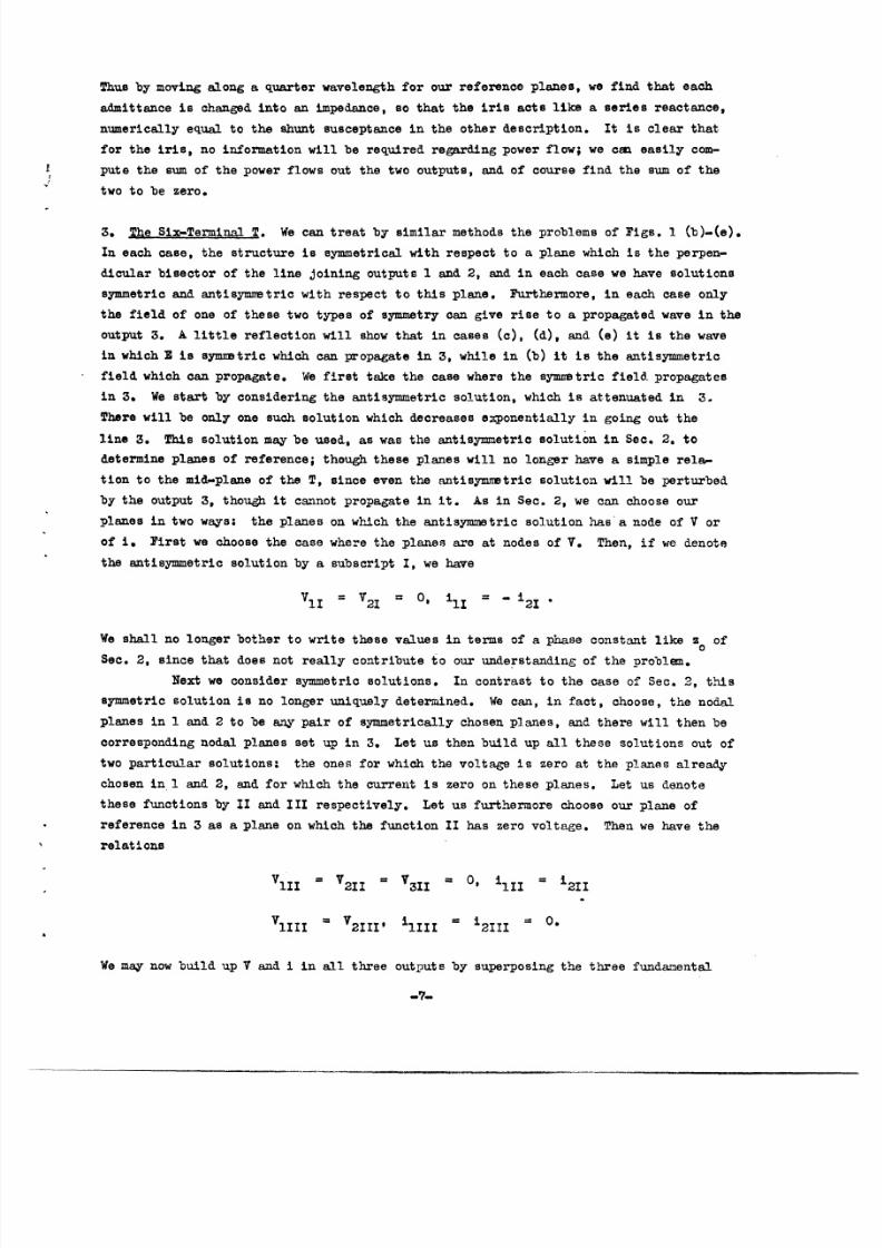
Thus by moving along a quarter wavelength for our reference planes, we find that each
admittance is changed into an impedance, so that the iris acts like a series reactance,
numerically equal to the shunt susceptance in the other description. It is clear that
for the iris, no information will be required regarding power flow; we can easily con-
pute the sum of the power flows out the two outputs, and of course find the sum of the
two to be zero.
3. The Six-Terminal T. We can treat by similar methods the problems of Figs. 1 (b)-(e).
In each case, the structure is symmetrical with respect to a plane which is the perpen-
dicular bisector of the line oining outputs 1 and 2, and in each case we have solutions
symmetric and antisymmetric with respect to this plane. Furthermore, in each case only
the field of one of these two types of symmetry can give rise to a propagated wave in the
output 3. A little reflection will show that in cases (c), (d), and (e) it is the wave
in which E is symmtric which can propagate in 3, while in (b) it is the antisymmetric
field which can propagate. We first take the case where the symmetric field propagates
in 3. We start by considering the antisymmetric solution, which is attenuated in 3.
There will be only one such solution which decreases exponentially in going out the
line 3. This solution may be used, as was the antisymmetric solution in Sec. 2. to
determine planes of reference; though these planes will no longer have a simple rela
tion to the mid-plane of the T, since even the antisymmetric solution will be perturbed
by the output 3, though it cannot propagate in it. As in Sec. 2, we can choose our
planes in two ways: the planes on which the antisymmetric solution has a node of V or
of i. First we choose the case where the planes are at nodes of V. Then, if we denote
the antisymmetric solution by a subscript I, we have
Vl I = V2i = 0, i o 2I
We shall no longer bother to write these values in terms of a phase constant like so of
Sec. 2, since that does not really contribute to our understanding of the problem.
Next we consider symmetric solutions. In contrast to the case of Sec. 2, this
symmetric solution is no longer uniquely determined. We can, in fact, choose, the nodal
planes in 1 and 2 to be ay pair of symmetrically chosen planes, and there will then be
corresponding nodal planes set up in 3. Let us then build up all these solutions out of
two particular solutions: the ones for which the voltage is zero at the planes already
chosen in 1 and 2, and for which the current is zero on these planes. Let us denote
these functions by II and III respectively. Let us furthermore choose our plane of
reference in 3 as a plane on which the function II has zero voltage. Then we have the
relations
1II V2II = = 0, ill i2I I
VlIII V2 III ilIII = i2 II =
We may now build up V and i in all three outputs by superposing the three fundamental
-- · lls··-islPUI .. I-·----LI_·-Y·I-·Is- C^-· ----- I ·-

8/3/2019 J. C. Slater- The Theory of Symmetryical Waveguide T's
http://slidepdf.com/reader/full/j-c-slater-the-theory-of-symmetryical-waveguide-ts 12/20
solutions, as before, remembering that solution I vanishes in output 3. Thus we have
V1 V2 = IIVII' V3 = IIIV31II
i = CIil +I II
(8)
Ci +
is= IIi3II + CIIIi3III.
Combining these equations, we have
h BIXX .+a LV3 V3111 V3III 0III
L . i . tlIII (Il i2
V3III 2 V3III iIII V2
or
y3+
(Y+
Y2 ) = - Jbo,
V V Z
= I iliI ' Jbo = 3III Zo
This exhibits the admittance -Y3 looking into the terminal 3 as c(Y + bo, a
shunt combination of the admittances Y1 and Y2 looking out the other terminals, trans-
formed by a ratio a, and a fixed shunt susceptance jbo. As in Sec. 2, if we choose
our planes of reference a quarter wavelength out from the planes already considered,each admittance is transformed into an equal impedance, and we have
Z3 + (Z1 + Z2 ) = -Jxo , (10)
where x = b o . If we choose, we can of course go out a quarter wavelength in some of
the outputs, not in others, obtaining a mixed set of planes, across some of which we are
to use admittances, across others impedances.
We next consider the flow of power. It is of course true that the net flow
out of all outputs is zero, but now the distribution among the outputs is of interest,
and is uniquely determined if the Y's or Zs are known. If we let PI, P2' P3 be the
power flows out the three outputs, we have
P:PZ:P3 = Re V1 1 :Re V2 i 2Re V3 i3
= al V1l :G2 v12 :G 3 1V3 12
-8 -

8/3/2019 J. C. Slater- The Theory of Symmetryical Waveguide T's
http://slidepdf.com/reader/full/j-c-slater-the-theory-of-symmetryical-waveguide-ts 13/20
where G1, G2 , G3 are the real parts of Y1, Y2 9 Y3. But from (8) we can solve for
V1, V2, V.. Cancelling the common factors, we have
P1:P2 P3 = G1: 2:G3 V1II
But using the real part of (9), we have
G3 (G 1+
2) = O, 3 -(G1+G2 )'
so that,using the value of a,
i I VII
P1 :P 2 :P 3 = G1 2 1II V1I1 + G2 )
Now we remember that P+P2+P3 must be zero; hence it must be that
2 V
G + + (Gl + 2) 0,
22i1II III 2 )
2(iIXVMII) + i3IIVZII = ±1 IIV 1I +i i2III + i31 V31 1 = 0.
Thus we have proved a relation between the solutions II and III which must be true by
general principles, and which will automatically be true if we have determined-these
solutions correctly from theory. We then finally have
Pi:P2:P3 - G; G2 -(Gl G2)' (12)
In a similar way, using the second choice of reference planes, which led to (10), we can
show that
P1 :?2 :P 3 = l: :-(1 + R2)' (13)
where E1 , R2 are the real parts of the impedances Z,* Z2.
By a method analogous to that used so far, we can consider the E-plane T of
Pig. 1 (b), and show that the same final results (9), (10), (12), (13) hold for it that
hold for the other types of T s.
Having Eq. (9) for the admittances, it is easy for us to devise experiments
for determining the planes of reference, and the constants and bo . One such method is
the following. -In output insert a plunger, so that by varying its position we can
make Y, take on any purely reactive value. Feed power into 3, and determine the power
coming out 2. Adjust the plunger so that no power comes out 2. This must mean that no
power enters 3, so that Y3 is an infinite susceptance. This, by (9), arises only if I
is an infinite susceptance. Thus the plunger in 1, under those circumstances, is at the
-9-
__________1__1_1_·_·l̂ ·lql____ll__ --·- - ·--·I

8/3/2019 J. C. Slater- The Theory of Symmetryical Waveguide T's
http://slidepdf.com/reader/full/j-c-slater-the-theory-of-symmetryical-waveguide-ts 14/20
plane of reference. In a similar way we can find the plane of reference in 2; if the T
is perfectly constructed, of course it will be at the same distance as that in 1. In
the process of making these observations, let there be a standing-wave probe in output
3, and let the position of standing-wave minima be observed, when the plunger is
adjusted to allow no power to flow out 2. There will of course be an infinite standing-
wave ratio. Since Y3 = oO under these circumstances, the plane of reference in 3 must
be at a standing-wave minimum. This experiment determines the planes of reference. To
find a and bo, let outputs 1 and 2 now have matched loads, or let 1 be open circuited,
2 matched. Then Y1+
Y2 equals 2 or l, espectively, and -Y3 = 2 + jbo or (a + Jbo.
peed power into 3, measure the standing-wave ratio and position of standing-wave minima,
and from familiar methods we find the admittance, and hence 0. and b0 .
We note that the admittance of the T through the output 3 is -Y3 = (y +Y2 )+Jb
For some purposes it is desired to modify a T so that we shall have bo = 0, and a = 1
or 1/2. In the first case, open-circuiting output 1 (setting Y1 = 0), and matching
output 2 (setting 2 = 1), we find -Y3 = 1, or we see a match in output 3; in the second
,case, matching both 1 and 2, setting Y1 = Y2 = 1, we see a match in 3. These are two
types of matched TIs. Either of these purposes can be accomplished by putting a proper
transformer in line 3. With a waveguide output for 3, the transformer can take the form
of a suitably placed and constructed iris. Suppose for instance that we wish to make
a = 1, bo = 0. With Y+Y2 = 1, the input admittance seen in line 3 is + bo, across
the plane of reference. Across other planes, however, this admittance will be different.
Let us go along the line to a point such that the real part of the admittance is unity.
The imaginary part will in general be different from zero at this point; insert there an
iris ust sufficiently reactive to cancel this susceptance. Then by the principles of
Sec. 2, the admittance seen looking into the output 3 across the plane of the iris will
be unity. Now regard the T and its iris as a new T, applying an analysis of the sort
leading to Eq. (9). This analysis must apply to the new matched T; but since this leads
to -Y3 = 1 when Y1+
Y2 = 1, it can only be that the matched T has = 1, bo = O, as we
desired, and that its properties are given by Y1+Y2 + Y3 = 0. Under these conditions,
all distinction between outputs 1, 2, and 3 is lost, and there is complete electrical
symmetry in the T. This matched T will not in general have its plane of reference in
output 3 in the same place that it had before the iris was inserted, and the plane must
be redetermined as described above.
4. The Eight-Terminal or "Iaic" . The magic T is essentially a combination of the
E-plane and H-plane T's of Fig. 1 (b) and (c). Fields in which E is symmetrical in
1 and 2 will be propagated in output 3 but not in 4, whereas those antisymmetric in 1
and 2 will be propagated in 4 but not in 3. There is now no unique way to determine the
reference planes. Let us therefore choose symmetrically placed planes in 1 and 2 in an
arbitrary manner. We then set u four standing waves, two antisymmetric, two symmetric.
Of each variety, one will have V = 0 at the planes of reference in 1 and 2, and one will
have i = 0 at those planes. Let us now choose the planes of reference in 3 and 4 in the
following way: in 3, we choose it so that the antisymmetric function which has zero
-10-

8/3/2019 J. C. Slater- The Theory of Symmetryical Waveguide T's
http://slidepdf.com/reader/full/j-c-slater-the-theory-of-symmetryical-waveguide-ts 15/20
voltage across the reference planes in 1 and 2 likewise has zero voltage across the
reference plane in 3; in 4, we choose it so that the symmetric function which has zero
voltage across the planes in 1 and 2 has zero voltage across the plane in 4. Thus we
have the following situation:
V = = VII V21 3 V41 = , illI = i2 I, i41 = 0
VI = - V2II, V4Il O, ilI I = i2I I i4I I = 0
V v v v 01III= 7211 V3III V4III = ,lii i2iii, i3III
VlIV V2IV' V3IV = 0, ilV = i V = i3IV = 0.
The voltages and currents at the various reference planes are then given by
v = OIIVI I + oIYV1IV' Va = CIIVII + OIVIV
V3 = CIiV3II, V4 = OIVV4 IV
(14)
i1 = iI + CIIIilIIi i2 - ili + OIi III
i3 = I3I + OIIi3II', 4 = IIIi4III + CIVi4IVO
From these, we can set up two equations,
i3 _ 3I + I
V3 V3II CII V311
i4 i41V .I i4II:
V4 V4IV IV V4IV
3= i3 llV3II V3II il
Vl-V2
= 4_ZV 4II (fi+2)
V4IV V4IV IIII vI+V2
These equations are similar to Eq. (9). As in that case, we let
(i3 /V3 )o = Y3 (i4/V4)Zo = Y4, (il/Vl)Zo = Y1 ' (i2/V2 )Zo Y2'
and have
Y3= - 4b :v(YlV Y2V2 ) b3 0 1 2
(15)
Y4 = - b4 - 4 +V
4~~~~
-11-
_=_ 1. II -----·-
i

8/3/2019 J. C. Slater- The Theory of Symmetryical Waveguide T's
http://slidepdf.com/reader/full/j-c-slater-the-theory-of-symmetryical-waveguide-ts 16/20
with
i1 1
4IV-Jb3 : 3II 0 4 V I
(16)
i V i VIi3I VlII' =-4 = V4I v II,
3 V3II il I I
We now eliminate V1 and V2 between Eqs. (15). From the first we have
V1(Y3 + jb 3 + a 3Y 1 = V2 (Y3 + jb 3+
3Y2 )
and from the second
V1(Y4+ jb 4 + 4 Y ) = - V2 (Y4 + b 4
+4 Y2 ). (17)
Setting the ratio V1/V2 from these two equations equal, we have finally
(Y3+ jb 3 ) (Y4 + jb4 )b 3 ) (Y4 +b 4
T'Y2+ x - "4 + (Y + Y2 ) 3 4_..... Y2_ : o. (18)
This is one form of the admittance equation for the magic T. By choosing planes a quarter
wavelength further out in each of the outputs, we can transform each admittance into an
impedance, and have an expression identical to (18), but involving Z, Z2 Z3 Z4. By a
mixed choice of planes we can use impedances across some planes, admittances across
others, and this method sometimes has advantages.
The expression (18) takes on a particularly interesting form when 1 = Y2, or
when (Y3 + jb3 )/a. 3 = (Y4 + jb4 )/a4 ' In the first case it can be factored to form
Y(37Q ) 0,¥1 (19)4 +
`34
and in the second form
+jb 3 + Y) ( 3 3+ Y 0. (20)03
3
In case (19), one or the other factor must be zero. Thus suppose the first factor is
zero; we then have for the admittance seen looking into the output 3
- Y3 = jb3+
a3Y1 (21)
in close analogy to Eq. (9). Thus the admittance is independent of Y4 . The reason, as
we shall see shortly, is that with equal loads in 1 and 2, no power fed into output 3
proceeds to 4; it is all divided equally between 1 and 2. ence there is no effect of
the admittance in 4 on the admittance as seen in 3. Similarly, if the power is fed into
4, none will proceed into 3, and we shall have - Y4 = jb4 + a4Y1 .
-12-
I_ _I _ _-I _ -- -- -

8/3/2019 J. C. Slater- The Theory of Symmetryical Waveguide T's
http://slidepdf.com/reader/full/j-c-slater-the-theory-of-symmetryical-waveguide-ts 17/20
These results may be used to suggest a simple experimental method of determin-
ing the constants of the T. We remember that any symmetrically chosen pair of planes
in 1 and 2 may be taken as planes of reference in those outputs. Having chosen them,
place short-circuiting plungers at these planes, so that Y = Y2=<v. Then feed power
into output 3. By (21) we should have -Y3 = , or an infinite standing-wave ratio,
with the plane of reference in 3 at the standing-wave minimum. Next remove the plungers
and match 1 and 2, so that Y1 = Y2=
1. Then feeding power into 3 we observe the admit-
tance -Y3 = jb3+
2.3, from which b3 and 3 can be found by standing-wave measurement.
By similar methods in output 4 we find b4 and 4%. The results similar to (21), derived
from (20), are analogous to those already discussed, but less useful, for to realize them
experimentally, we must make (Y3 + jb3)/,3 = (Y4+
jb4)/ 4,' hich we cannot 'do until we
have determined b3, b4 ,3' 4*
Let us next consider the question of power flow. Proceeding as in Sec. 3, we
have
Pi:P 2 :P3:P4 = GlIVl2 : 12V1 ;G3 V31
2:G41 412. (22)
From (17) we can find the ratio of 1 to V2 . From (14) we find that
V3= 1 2 2),- = i 2 (23)1III 2 '14 IV
To evaluate the quantities V3II/V1II and V41V/1I' we consider relations like (11),
which must be true in order that the total power flow out from all outputs may equal
zero. The condition can be stated in the form
Ob k V i 0,
Re C ka Cb = Re ab k ka kb
where a, b go over the series I-IV, k over the outputs 1-4. For this to be true with
arbitrary Cs, we must have
= 0 (24)
This need be true only for a b; for a = b, since Vka is real, ika pure imaginary,
CaC a real, the real part of the term is automatically zero. Out of all the combinations
a, b, the only relations of the type (24) which are not trivial are
2il1V Ii + i3V1311 0
2i1IIIV1IV + i 4 IIIV 4V = O.
Combining these with definitions (16) of the cls, we see that
V1I I .a VIv1
_13-
_ __ _ __ _-1--·^-1.-·--- ----11111 -1--- · L

8/3/2019 J. C. Slater- The Theory of Symmetryical Waveguide T's
http://slidepdf.com/reader/full/j-c-slater-the-theory-of-symmetryical-waveguide-ts 18/20
Thus we can find V3 and V4 from (23) in terms of V1 and V2. Putting this information
together, we have from (22)
P1 :P2 :P3:P 4 =
G Y + j 2, -2 ( 3 +b 2
.. Y4Jb4 . 4 + Y + 5) 1 4Y2 - - +2 1 - a C
2+ jb 2 2+ 3 4 + jb 4 4 25 '2 3 2Y4 +bY'
44b l
Using (18), it is not difficult, though not at once obvious, to establish the other two
forms
pi:P:P3:P4
L 3 J3 4 44L b Y + .jb Y4 4+Jb 4 '
4 .2 1 01 3 "4. ~L -~~~~i
G3 Y4+ j b4 G4I
= 0 4 +4I
G+ a
2 2 2 3 %
(26)
Y4+
b4 2
:4
3 Y2+
These four expressions are equivalent to each other, but one particular one
will be most convenient in most cases. Thus if Y1 is nearly equal to Y2, and we are
feeding power into the output 3, so that we have approximately the situation described
in Eq. (21), we wish to use the second equation of (25). If Y1 = Y2, this reduces to a
simple form:
P1 :P2:P3 :P4 =
Y4 + b4 Y4+Jb4 2G- Y4
+Jb
| 4l1 :G Y 3 4.Y :0 .4 14' 04 +%
Taking the real part of (21), we have in this case -G3 = SG1. Thus we see that in this
case P1 :P2 :P3:P4 = 1:1:-2:0, or the power flowing into output 3 is equally divided
between 1 and 2, none flowing out 4, as we have mentioned earlier. If Y1 is not exactly
equal to Y2, however, (25) serves to give the power flowing out of output 4, and to show
that it is proportional to the square of the magnitude of Y2-Y1. The other equation (25)
-14-
Y2

8/3/2019 J. C. Slater- The Theory of Symmetryical Waveguide T's
http://slidepdf.com/reader/full/j-c-slater-the-theory-of-symmetryical-waveguide-ts 19/20
is useful if Y1 is nearly equal to Y2, but power is fed into output 4, and (26) similarly
is useful if (Y3 + b3)/c(3 is nearly equal to (Y4 + JbQ)/4'
In the equations which we have so far derived, there is not complete symmetry
between the outputs 1 and 2 on the one hand, 3 and 4 on the other, the admittances
Y1 and Y2 are balanced by the more complicated quantities (Y3 + Jb3)/0c and (Y4 + Jb4)/04
It is clear that to secure complete symmetry we should make b = b4 O, C = 04= 1.
This can be done, as in Sec. 3, by inserting suitable irises in outputs 3 and 4. The wayto do it is clear from (21). In this case (Y3 + b3)/a3 and (Y4
+ Jb4)/c4 wi1 be
replaced by Y and Y4 respectively in (18), (25), and (26), and there will be complete
symmetry between the two sets of outputs. Equation (21) will then become -Y3= Y1, showing
that if Y1 = Y2 = i, so that the two terminals 1 and 2 are matched, we shall se e a
match looking into output 3. For this reason a T with these characteristics is called
a matched magic T, and it is the type usually employed in practice.
__ _ 11 I I_____I___IIY__LII __ _1_1----_1 _ Ilyl^^-----_·l_ -- -~I -- --
-15-

8/3/2019 J. C. Slater- The Theory of Symmetryical Waveguide T's
http://slidepdf.com/reader/full/j-c-slater-the-theory-of-symmetryical-waveguide-ts 20/20