Embed Size (px)
DESCRIPTION
structural engineering
Citation preview
Enhancement of Lightly Reinforced Concrete Columns with Buckling-Restrained Reinforcement
Lukkunaprasit, P.Department of CivilEngineering, Chu-lalongkorn UniversityBangkok, [email protected]
Dr. P. Lukkunaprasit is Head of the Center of Excellence in Earthquake Engineering and Vibration at Chulalonkorn University, Thailand.
Tangbunchoo, T.Department of CivilEngineering, Chu-lalongkorn UniversityBangkok, [email protected]
Rodsin, K.Department of Civil andEnvironmental Engineering Technology, King Mon-gkut’s University of Tech-nology North BangkokBangkok, [email protected]
SummaryReinforced concrete columns with light confinement prevalent in developing countries exhibit low ductility, especially when buckling of longitudinal rebars takes place. Undesirable abrupt shear failure is generally triggered as a result. This study applies the buckling restraining concept widely used in seismic resistant steel structures to reinforcing bars. Two reinforced concrete columns 270mm x 300mm in cross section with a height of 1200 mm and minimum (non-seismic) transverse reinforcement were tested under cyclic lateral loading. Buckling-restrained reinforcement (BRR) was provided over the tie spacing above the lowest tie in the column. The specimens were cyclically loaded in the horizontal direction under a constant axial load ratios of 20% and 40% based on nominal compressive capacity of the section. The buckling-restraining casing effectively prevented buckling of slender vertical bars (length/diameter ratio of 18) under a significantly high axial load level , resulting in a more ductile mode of failure with evident formation of plastic hinge at the base of the column. At gravity load collapse, the drift capacities of the specimen were substantially increased compared to their counterparts without casings. An important finding from the tests is that the degraded concrete shear capacity reported in the literature without distinction of longitudinal bar buckling can be significantly underestimated especially at displacement ductility close to gravity load collapse.
Keywords: seismic performance, gravity load collapse, reinforced column tests, light confinement, longitudinal bar buckling, buckling-restrained reinforcement, degraded concrete shear capacity.
1.Introduction
Reinforced concrete (RC) columns with light longitudinal and transverse reinforcement are prevalent in existing low rise buildings in regions of low or even moderate seismicity, espe-cially in developing countries. These structures are vulnerable to damage or even collapse in the event of a strong earthquake. Unfortunately, research work on lightly reinforced concrete columns is quite limited. RC columns with light transverse steel subjected to cyclic lateral load exhibit rapid loss of lateral load resistance soon after attaining the peak capacity. Shear mode of failure often prevails with small drift capacity [1],[2]. Under moderate to high axial load ratios, longitudinal bars tend to buckle, with the consequence of abrupt shear failure as reported by Ari et al.[3]. Sezen and Moehle [4] earlier reported that for columns with light axial load, shear failure would be triggered due to apparent strength degradation after devel-opment of the flexural strength whereas columns with high axial load would suffer abrupt shear compression failure.
It was speculated that preventing longitudinal bar buckling would greatly enhance the seismic performance of RC columns since it reduces the transfer of gravity load from the steel to con-crete, thereby reducing the shear on the diagonal crack plane. Buckling restraining casings were provided over the potential plastic hinge zone in a RC specimen cyclically loaded in the horizontal direction. Performances of RC columns with and without casings are compared.
2.Performance of control columns without buckling-restraining casingThe specimens S2 and S3 tested by Ari et al. [3] serve as the control specimens. The col-umns, 270mm×300mm in cross section, were reinforced with four ø16 mm Grade 400 MPa longitudinal steel bars. Hoop ties, 6 mm in diameter, were provided at 300mm spacing corre-sponding to a transverse reinforcement ratio rH of 0.0007. The nominal concrete compressive strength fc' was 20 MPa. The column was loaded in single curvature under cyclic loading with the lateral load applied at a height of 1200 mm from the base. A constant axial load of 20% the axial load capacity based on fc'Ag was applied to specimen S2, while that for S3 was 40%.
The specimens exhibited flexure dominated inelastic behavior with well distributed flexural cracks up to the peak strength at about 1.5??% and 1.0% drifts for specimens S2 (20% axial load ratio) and S3 (40% axial load ratio), respectively.1.0 %. Soon after the peak load, previously de-veloped vertical cracks widened, indicating impending vertical bar buckling. The drift capac-ity was ….. % with sustainable lateral load capacity of ……..% of the peak value for S2. The corresponding values are1.25% drift and 98 % of the peak capacity, respectively. Note that these drifts are very close to those at peak loads. At impending failure upon visible longitudi-nal bars buckling (at …% and 1.5% drifts for S2 and S3, respectively), vertical bars buckled in the potential buckling zone near the base followed by an abrupt transfer of the force carried by steel to the concrete core with a consequence of significant increase in shear along the cracked shear plane. This triggered an abrupt shear failure (due to deterioration of cyclic shear resistance) and loss of gravity load capacity, which resulted in a sharp drop in the de-scending branch of the envelope curve. Furthemore, the failure shear plane cut through the concrete core at roughly 45º in between the ties. Thus, practically no shear resistance was provided by the transverse reinforcement at the failed section.
Based on the test results, it is natural to speculate that the performance of such columns would be enhanced should the longitudinal bars be prevented from buckling. If such is the case, the drift capacity would also be improved.
3.Buckling restrained reinforcement
An attempt has been made earlier by Ruangrassamee and ….[5] to develop a device to prevent rebars from buckling using rebar-restraining collars, which were tight- fitted to encase the rebars without any unbonding material separating them.
However, in this investigation, the concept of buckling restrained brace successfully used in steel structures for enhancing seismic performance of steel buildings was adopted. In our pioneer study, ø 28 mm steel tubes with 4mm-thickness were used to encase the ø16 mm longitudinal bars. The deformed bars were coated with silicone to a practically smooth surface and subsequently wrapped with plumber’s tape. Non-shrink grout was then injected into the void between the Fig. 1: Compressive stress-strain relationships
of 16mm diameter bar with and without casing.

wrapping and the steel casing. The stress-strain relationships of the steel bar with and without casing under compressive loading are shown in Fig. 1. The length of the bars between the grips was 300 mm. For BRR, the length of the casing was 250mm. As expected, right after peak load, the capacity of the bare steel bar sharply drops due to bar buckling. In contrast, the buckling-restrained reinforcing bar could sustain almost constant load after yielding since the lateral restraint provided by the casing prevents the bar from buckling. Interestingly, even at a large axial strain of 4%, BRR could sustain a stress as high as 90% of the peak value.
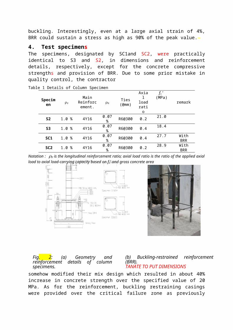
4. Test specimensThe specimens, designated by SC1and SC2, were practically identical to S3 and S2, in di-mensions and reinforcement details, respectively, except for the concrete compressive strengths and provision of BRR. Due to some prior mistake in quality control, the contractor
Table 1 Details of Column Specimen
Speci-men
rV
MainReinforce-
ment.rH
Ties(@mm)
Axial load ratio
fc’(MPa) remark
S2 1.0 % 4Y16 0.07 % R6@300 0.2 21.0
S3 1.0 % 4Y16 0.07 % R6@300 0.4 18.4
SC1 1.0 % 4Y16 0.07 % R6@300 0.4 27.7 With BRR
SC2 1.0 % 4Y16 0.07 % R6@300 0.2 28.9 With BRR
Notation : rV is the longitudinal reinforcement ratio; axial load ratio is the ratio of the applied axial load to ax-ial load-carrying capacity based on fc' and gross concrete area
somehow modified their mix design which resulted in about 40% increase in concrete strength over the specified value of 20 MPa. As for the reinforcement, buckling restraining casings were provided over the critical failure zone as previously experienced by specimens S2 and S3, i.e. over the lowest tie spacing of 300mm. Details are presented in Table 1 and Figure 2.
4.Test set up
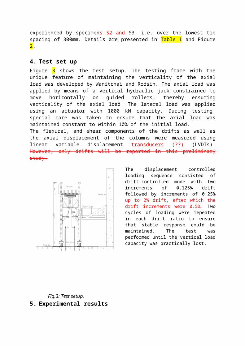
Figure 3 shows the test setup. The testing frame with the unique feature of maintaining the verticality of the axial load was developed by Wanitchai and Rodsin. The axial load was ap-plied by means of a vertical hydraulic jack constrained to move horizontally on guided
Fig. 2: (a) Geometry and reinforcement details of column specimens.
(b) Buckling-restrained reinforcement (BRR).TANATE TO PUT DIMENSIONS
rollers, thereby ensuring verticality of the axial load. The lateral load was applied using an actuator with 1000 kN capacity. During testing, special care was taken to ensure that the axial load was maintained constant to within 10% of the initial load.The flexural, and shear components of the drifts as well as the axial displacement of the col-umns were measured using linear variable displacement transducers (??) (LVDTs). However, only drifts will be reported in this preliminary study.
The displacement controlled loading sequence consisted of drift-controlled mode with two in-crements of 0.125% drift followed by increments of 0.25% up to 2% drift, after which the drift in-crements were 0.5%. Two cycles of loading were repeated in each drift ratio to ensure that stable response could be maintained. The test was per-formed until the vertical load capacity was practi-cally lost.
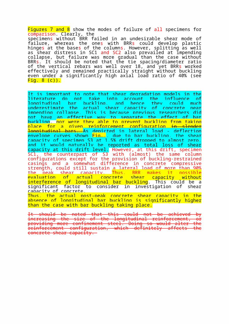
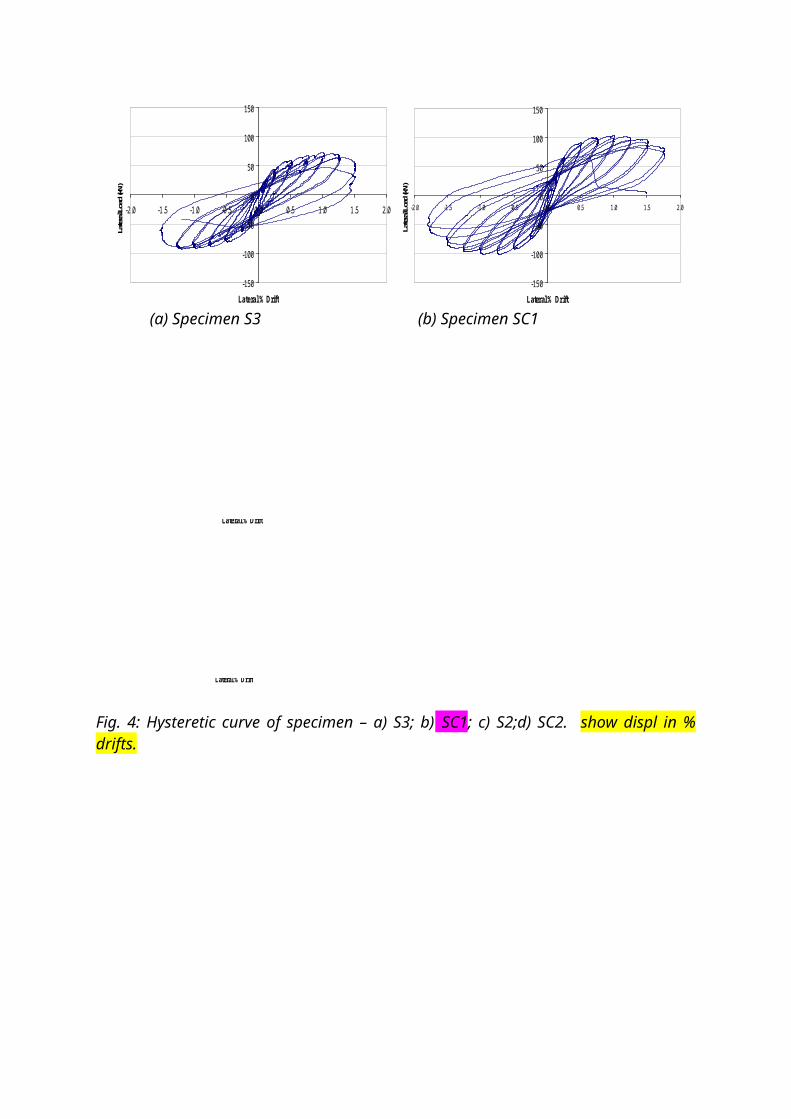
5.Experimental results Figure 4 shows the hysteretic loop of specimens SC1 and SC2 together with S3 and S2 for comparison. Specimens SC1 and SC2 with BRRs experienced relatively less cracking than their counterparts at the same drift ratio as illustrated in Fig. 5. As expected, the buckling-re-straining casing effectively prevented buckling of rebars in the zone reinforced with BRR. Specimens SC1 and SC2 could sustain the gravity load with stable hysteretic loops past the peak load with relatively more gradual drop in capacity as evident in the envelope curves de-picted in Fig. 6. While specimen S2 and S3 could not sustain lateral load of 80% of the peak load at …% drift, their counterparts with BRRs could still sustain the lateral load resistance at this level with a drift of about 1.7% and …%, respectively. Prior to gravity load collapse, the drift capacity of specimen SC1 was 1.75%, a 40% increase compared to the specimen without casing. The improvement was much greater for specimen SC2 (under an axial load ratio of 0.2) which sustained the gravity load up to a drift of 4.5% whereas the specimen without BRR reached gravity load collapse at 2% drift.
An investigation of the strains in the longitudinal rebars reveals that, soon after the peak loads, they reached compression yield strain at about …% and …% drift ratios for specimens SC1 and SC2, respectively (see Fig. …). Interestingly, the rebars in their counterparts S3 and S2 buckled soon after reaching the compressive yield strain. This clearly confirms that the re-bars in the specimens with buckling-restrained casings would have buckled if they were bare bars, with subsequent abrupt failure not far from those drift levels.DR. KITTIPOOM, I THINK IT WOULD BE WORTHWHILE TO ADD FIGS SHOWING AXIAL COMPRESSION STRAINS VS DRIFTS (BUT HOW GOOD ARE THE data?? IF YES, SHOW ONLY ONE PLOT TO SAE SPACE)
Fig.3: Test setup.
(a) (b)
Figure… (a) Specimen S2 at 2% drift, (b) specimen S3 at 1.5% drift
(c) compressive strain in the longitudinal rebars of the specimens S2, S3, SC1 and SC2 ver-sus lateral drift.
0
500
1000
1500
2000
2500
3000
3500
4000
4500
0 0.5 1 1.5 2 2.5 3
Co
mp
ress
ive
Str
ain
(x
10-
6 )
Drift (%)
SC1
SC2
S2
S3
yield strain
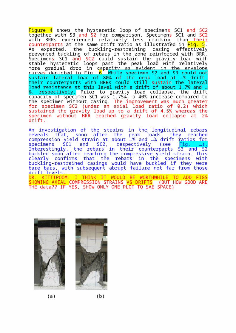
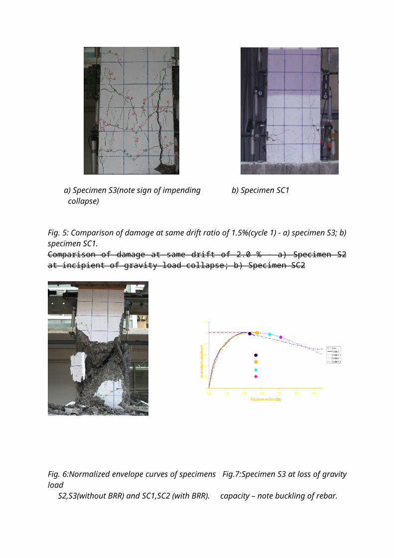
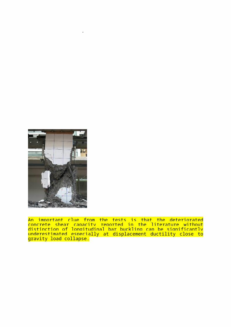
Figures 7 and 8 show the modes of failure of all specimens for comparison. Clearly, thespecimens without BRR failed in an undesirable shear mode of failure, whereas the ones with BRRs could develop plastic hinges at the bases of the columns. However, splitting as well as shear distress in SC1 and SC2 also prevailed at impending collapse, but failure was more gradual than the case without BRRs. It should be noted that the tie spacing/diameter ratio of the vertical rebars was well over 18, and yet BRRs worked effectively and remained practi-cally straight without buckling even under a significantly high axial load ratio of 40% (see Fig. 8 (c)).
It is important to note that shear degradation models in the literature do not take into account the influence of longitudinal bar buckling, and hence they could much underestimate the ac-tual shear capacity of concrete near impending collapse. This is because previous researchers did not have an effective way to separate the effect of bar buckling, nor were they able to pre-vent buckling from taking place for a given reinforcement configuration in slender longitudi-nal bars. As depicted in lateral load - deflection envelope curves shown Fig…., due to bar buckling, the shear capacity of specimen S3 at 1.5% drift dropped to almost zero, and it would naturally be reported as total loss of shear capacity at this drift level. However, at this drift, specimen SC1, the counterpart of S3 with (almost) the same column configurations ex-cept for the provision of buckling-restrained casings and a somewhat difference in concrete compressive strength, could still sustain a lateral load of more than 90% the peak shear ca-pacity. Thus, BRR makes it possible evaluation of actual concrete shear capacity without in-terference of longitudinal bar buckling. This could be a significant factor to consider in in-vestigation of shear capacity of concrete. Thus, the actual post-peak concrete shear capacity in the absence of longitudinal bar buckling is significantly higher than the case with bar buckling taking place.
It should be noted that this could not be achieved by increasing the size of the longitudinal re-inforcement, or providing more confinement steel. Doing so would alter the reinforcement configuration, which definitely affects the concrete shear capacity.

-150
-100
-50
0
50
100
150
-2.0 -1.5 -1.0 -0.5 0.0 0.5 1.0 1.5 2.0
Lateral % Drift
Late
ral L
oad
(kN)
-150
-100
-50
0
50
100
150
-2.0 -1.5 -1.0 -0.5 0.0 0.5 1.0 1.5 2.0
Lateral % Drift
Later
al Lo
ad (k
N)
(a) Specimen S3 (b) Specimen SC1
-150
-100
-50
0
50
100
150
-6.0 -4.0 -2.0 0.0 2.0 4.0 6.0
Lateral % Drift
-150
-100
-50
0
50
100
150
-4.0 -3.0 -2.0 -1.0 0.0 1.0 2.0 3.0 4.0
Lateral % Drift
Fig. 4: Hysteretic curve of specimen – a) S3; b) SC1; c) S2;d) SC2. show displ in % drifts.
a) Specimen S3(note sign of impending b) Specimen SC1 collapse)
Fig. 5: Comparison of damage at same drift ratio of 1.5%(cycle 1) - a) specimen S3; b) spec-imen SC1.Comparison of damage at same drift of 2.0 % - a) Specimen S2 at incipient of gravity load collapse; b) Specimen SC2
Fig. 6:Normalized envelope curves of specimens Fig.7:Specimen S3 at loss of gravity load S2,S3(without BRR) and SC1,SC2 (with BRR). capacity – note buckling of rebar. .
0
0.2
0.4
0.6
0.8
1
1.2
0.00 1.00 2.00 3.00 4.00 5.00 6.00
Displacement Ductility
Norm
alize
d La
tera
l Loa
d Sezen
Ductility S2
Ductility SC-1
Ductility S3
Ductility SC-2
Vertical rebar buckled in S2
Vertical rebar buckled in S3
Yield in compression in SC-1
Yield in compression in SC-2
An important clue from the tests is that the deteriorated concrete shear capacity reported in the literature without distinction of longitudinal bar buckling can be significantly underestimated especially at displacement ductility close to gravity load collapse.
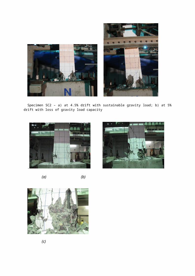
Specimen SC2 – a) at 4.5% drift with sustainable gravity load; b) at 5% drift with loss of gravity load capac-ity
.
(a) (b)
(c)
Fig. 8: Specimen SC1 – a) at 1.75% drift with sustainable gravity load; b) at 2% drift with loss of gravity load capacity – note no buckling of BRR as evident from c).
6.Conclusions
The buckling-restrained reinforcement developed has demonstrated its potential in preventing
buckling of slender vertical bars (length/diameter ratio of 18) under a significantly high axial
load level in the column specimen tested. This resulted in a more ductile mode of failure with
evident formation of plastic hinge at the base of the column. At gravity load collapse, the drift
capacity of the specimen was 1.75%, a 40% increase compared to its counterpart without
casing. Clearly more extensive experiments are needed to fully investigate the effectiveness
of BRR over a wide range of applications.
• Buckling of longitudinal bars with large tie spacing (L/db >18 !) leads to an abrupt
transfer of axial load from the steel bars to the concrete, thereby triggering shear fail-
ure due to deterioration of concrete shear strength during cyclic loading.
• Shear failure can be deferred or even eliminated when BRR is provided in the critical
zone to prevent bar buckling.
• For the specimens tested, BRR enhances significantly the drift capacity at gravity load
collapse as well as the degraded shear capacity of concrete.
• Past concrete shear strength degradation models without accounting for longitudinal
bar buckling can be in error, especially for lightly reinforced columns. Thus, …
• For columns with bar buckling taking place, Sezen-Moehle model for shear capacity
degradation much over-estimates the capacity close to impending gravity load col-
lapse. However, it gives good prediction of deterioration rate when buckling is pre-
vented. IN NEXT PAPER!!
•
7.Acknowlegements
The authors are grateful for the funding from the Commission on Higher Education, Ministry of Education and Chulalongkorn University.
8.References
[1] LYNN A.C., MOEHLE J.P., MAHIN S.A., and HOLMES W.T., “Seismic Evaluation of Existing Reinforced Concrete Columns”, Earthquake Spectra, Earthquake Engineer-ing Research Institute, V.12, No.4, Nov.1996, p.715-739.
[2] SEZEN H., and MOEHLE J.P, “Shear strength model for lightly reinforced concrete col-umns”, Journal of Structural Engineering, ASCE, 130(11), 2004, p. 1692-1703.
[3] WIBOWO A., WILSON J.L., FARDIPOUR M., LAM N.T.K., RODSIN K., LUKKU-NAPRASIT P., and GAD E.F., “Seismic Performance Assessment of Lightly Rein-forced Concrete Column”, The 21st Australasian Conference on the Mechanics of Structures and Materials, Dec. 2010.
[4] SEZEN H., and MOEHLE J.P, “Seismic tests of concrete columns with light transverse reinforcement”, ACI Journal, 103(6), 2006, p. 842-849.
[5] RUANGRASSAMEE A., and SAWAROJ A., “Seismic Enhancement of Reinforced-Concrete Columns by Rebar-Restraining Collars”, Earthquake Engineering and Struc-tural Dynamics, 2010, under review.
[6] PRIESTLEY M.J.N., VERMA R., and XIAO Y., “Seismic shear strength of reinforced concrete column”. Journal of Structural Engineering, ASCE, 120(8), 1994, p.2310-2329.
[7] FEMA-273, NEHRP guideline for the seismic rehabilitation of buildings, Federal Emer-gency Management Agency. Washington DC, USA. 1997.


![THEME [SC1-DTH-03-2018]](https://img.pdfslide.us/doc/110x75/617d706653c4da530e6e24ea/theme-sc1-dth-03-2018.jpg)