Embed Size (px)
Citation preview
2 ICP DAS CO., LTD. Professional Provider of High Quality Industrial Computer Products and Data Acquisition Systems Vol. iWSN 1.08.01
OverviewWith the trend toward smart manufacturing and fl exible manufacturing, the production process is becoming increasingly complicated, and each production stage is interlocked. The condition of the equipment is evaluated using the concept of predictive maintenance to maintain the operation of the production line. In response to the Internet of Things (IoT), big data analysis, Industry 4.0, energy-saving and carbon-reduction requirements, ICPDAS has developed the "Industrial Wireless Sensor Network" solution. In addition to integrating current, temperature measurement, and wireless transmission functions into a single module, the ultralow power consumption can be matched with a current transformer (CT) for inductive charging, it can meet the supply and demand balance of working power and supply the required continuous uninterrupted measurement equipment parameters with sufficient power. The settings can be completed using a DIP switch, which not only doesn't affect the production process, but also greatly saves system construction time and reduces maintenance costs. To meet the power consumption needs of monitoring equipment, predictive maintenance and power panel temperature monitoring, it's helpful to maintain the production line equipment and prevent accidents caused by the aging of power panel equipment and cables.
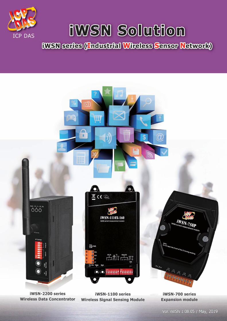
iWSN Solution
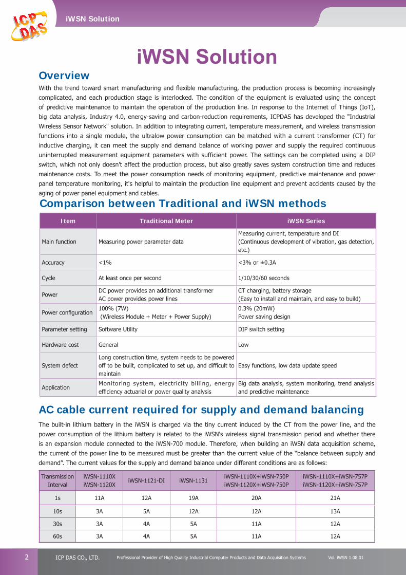
Comparison between Traditional and iWSN methods
AC cable current required for supply and demand balancing
Item Traditional Meter iWSN Series
Main function Measuring power parameter dataMeasuring current, temperature and DI(Continuous development of vibration, gas detection, etc.)
Accuracy <1% <3% or ±0.3A
Cycle At least once per second 1/10/30/60 seconds
PowerDC power provides an additional transformerAC power provides power lines
CT charging, battery storage(Easy to install and maintain, and easy to build)
Power confi guration100% (7W) (Wireless Module + Meter + Power Supply)
0.3% (20mW)Power saving design
Parameter setting Software Utility DIP switch setting
Hardware cost General Low
System defectLong construction time, system needs to be powered off to be built, complicated to set up, and diffi cult to maintain
Easy functions, low data update speed
ApplicationMonitoring system, electricity bil l ing, energy effi ciency actuarial or power quality analysis
Big data analysis, system monitoring, trend analysis and predictive maintenance
Transmission Interval
iWSN-1110XiWSN-1120X
iWSN-1121-DI iWSN-1131iWSN-1110X+iWSN-750PiWSN-1120X+iWSN-750P
iWSN-1110X+iWSN-757PiWSN-1120X+iWSN-757P
1s 11A 12A 19A 20A 21A
10s 3A 5A 12A 12A 13A
30s 3A 4A 5A 11A 12A
60s 3A 4A 5A 11A 12A
The built-in lithium battery in the iWSN is charged via the tiny current induced by the CT from the power line, and the power consumption of the lithium battery is related to the iWSN's wireless signal transmission period and whether there is an expansion module connected to the iWSN-700 module. Therefore, when building an iWSN data acquisition scheme, the current of the power line to be measured must be greater than the current value of the “balance between supply and demand”. The current values for the supply and demand balance under different conditions are as follows:
iWSN Solution
3http://www.icpdas.com Vol. iWSN 1.08.01
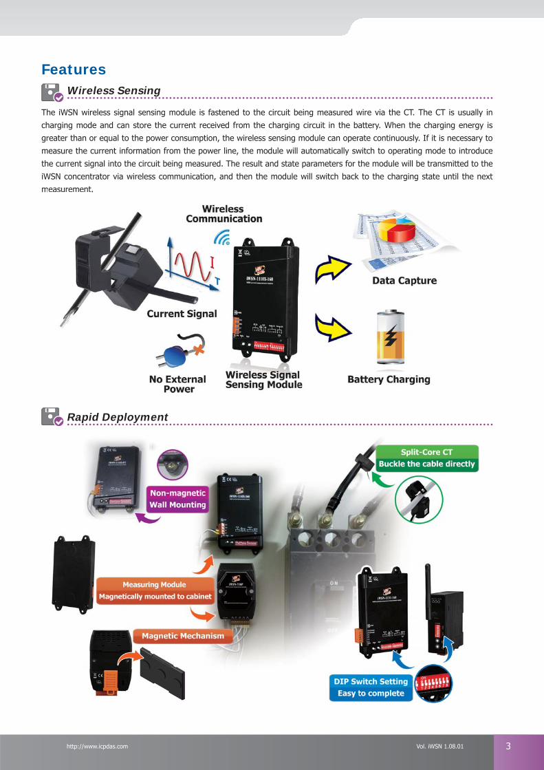
Features
The iWSN wireless signal sensing module is fastened to the circuit being measured wire via the CT. The CT is usually in charging mode and can store the current received from the charging circuit in the battery. When the charging energy is greater than or equal to the power consumption, the wireless sensing module can operate continuously. If it is necessary to measure the current information from the power line, the module will automatically switch to operating mode to introduce the current signal into the circuit being measured. The result and state parameters for the module will be transmitted to the iWSN concentrator via wireless communication, and then the module will switch back to the charging state until the next measurement.
Rapid Deployment
Wireless Sensing
easurement.
4 ICP DAS CO., LTD. Professional Provider of High Quality Industrial Computer Products and Data Acquisition Systems Vol. iWSN 1.08.01
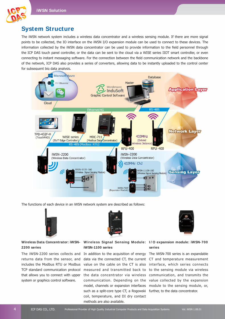
The functions of each device in an iWSN network system are described as follows:
Wireless Data Concentrator: iWSN-2200 series
The iWSN-2200 series collects and returns data from the sensor, and includes the Modbus RTU or Modbus TCP standard communication protocol that allows you to connect with upper system or graphics control software.
Wireless Signal Sensing Module: iWSN-1100 series
In addition to the acquisition of energy data via the connected CT, the current value on the cable on the CT is also measured and transmitted back to the data concentrator via wireless communication. Depending on the model, channels or expansion interfaces such as a split-core type CT, a Rogowski coil, temperature, and DI dry contact methods are also available.
I/O expansion module: iWSN-700 series
The iWSN-700 series is an expandable CT and temperature measurement interface, which series connects to the sensing module via wireless communication, and transmits the value collected by the expansion module to the sensing module, or, further, to the data concentrator.
System StructureThe iWSN network system includes a wireless data concentrator and a wireless sensing module. If there are more signal points to be collected, the IO interface on the iWSN I/O expansion module can be used to connect to these devices. The information collected by the iWSN data concentrator can be used to provide information to the fi eld personnel through the ICP DAS touch panel controller, or the data can be sent to the cloud via a WISE series IIOT smart controller, or even connecting to instant messaging software. For the connection between the fi eld communication network and the backbone of the network, ICP DAS also provides a series of converters, allowing data to be instantly uploaded to the control center for subsequent big data analysis.of the network, ICP DAS also provides a series of converters, allowing data to be instantly uploaded to the control center for subseqquent bigg data analysy is.
iWSN Solution
5http://www.icpdas.com Vol. iWSN 1.08.01
Applications
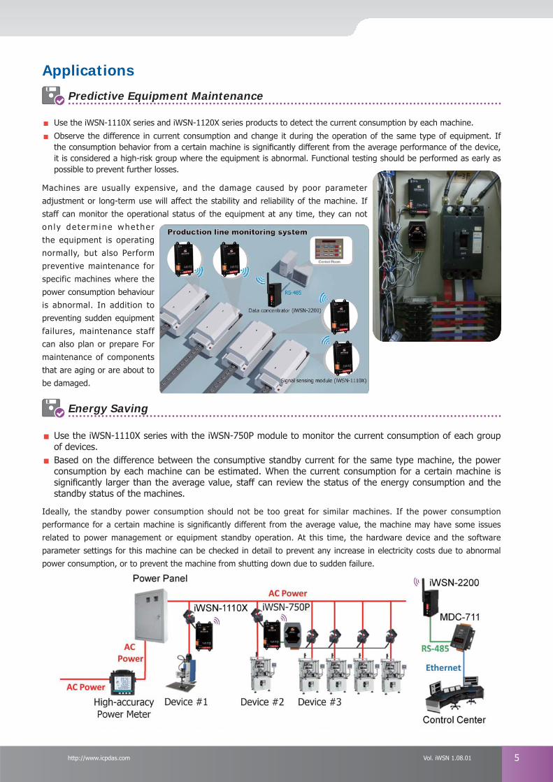
Use the iWSN-1110X series and iWSN-1120X series products to detect the current consumption by each machine.
Observe the difference in current consumption and change it during the operation of the same type of equipment. If the consumption behavior from a certain machine is signifi cantly different from the average performance of the device, it is considered a high-risk group where the equipment is abnormal. Functional testing should be performed as early as possible to prevent further losses.
Machines are usually expensive, and the damage caused by poor parameter adjustment or long-term use will affect the stability and reliability of the machine. If staff can monitor the operational status of the equipment at any time, they can not on ly de te rmine whether the equipment is operating normally, but also Perform preventive maintenance for specific machines where the power consumption behaviour is abnormal. In addition to preventing sudden equipment failures, maintenance staff can also plan or prepare For maintenance of components that are aging or are about to be damaged.
Predictive Equipment Maintenance
Energy Saving
Use the iWSN-1110X series with the iWSN-750P module to monitor the current consumption of each group of devices.
Based on the difference between the consumptive standby current for the same type machine, the power consumption by each machine can be estimated. When the current consumption for a certain machine is signifi cantly larger than the average value, staff can review the status of the energy consumption and the standby status of the machines.
Ideally, the standby power consumption should not be too great for similar machines. If the power consumption performance for a certain machine is signifi cantly different from the average value, the machine may have some issues related to power management or equipment standby operation. At this time, the hardware device and the software parameter settings for this machine can be checked in detail to prevent any increase in electricity costs due to abnormal power consumption, or to prevent the machine from shutting down due to sudden failure.
6 ICP DAS CO., LTD. Professional Provider of High Quality Industrial Computer Products and Data Acquisition Systems Vol. iWSN 1.08.01
Machine Diagnosis
Use the iWSN-1121-DI-240 module to monitor the current data on the panel.
The two CT channels on the iWSN-1121-DI-240 module are used to detect the total current consumption of both the device and the main motor so as to determine whether the machine is in either standby or running condition.
The fl oorspace of some factories is large and contains a lot of equipment. If the owner of the factory can keep track of the production status of each machine, the problem where the waiting time or standby time is too long can be avoided. The traditional method is for the employees to fi ll in the operating time themselves. Not only does it take time to organize this information, it is also impossible to control the artifi cial fl oating time behavior and dynamically understand the productivity of the production line machine. The iWSN network system provides the staff with an instant understanding of the operating status of the fi eld production line, while, in addition, also giving an indication where any necessary raw materials need to be immediately replenished, allowing the machine to continue to operate effi ciently and achieve optimal production capacity.
Monitoring the Utilization of a Machine
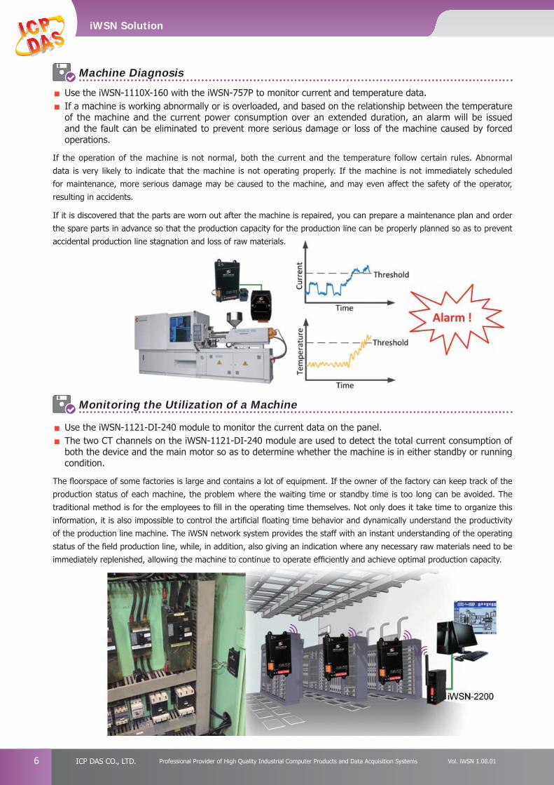
Use the iWSN-1110X-160 with the iWSN-757P to monitor current and temperature data.
If a machine is working abnormally or is overloaded, and based on the relationship between the temperature of the machine and the current power consumption over an extended duration, an alarm will be issued and the fault can be eliminated to prevent more serious damage or loss of the machine caused by forced operations.
If the operation of the machine is not normal, both the current and the temperature follow certain rules. Abnormal data is very likely to indicate that the machine is not operating properly. If the machine is not immediately scheduled for maintenance, more serious damage may be caused to the machine, and may even affect the safety of the operator, resulting in accidents.
If it is discovered that the parts are worn out after the machine is repaired, you can prepare a maintenance plan and order the spare parts in advance so that the production capacity for the production line can be properly planned so as to prevent accidental production line stagnation and loss of raw materials.
iWSN Solution
7http://www.icpdas.com Vol. iWSN 1.08.01
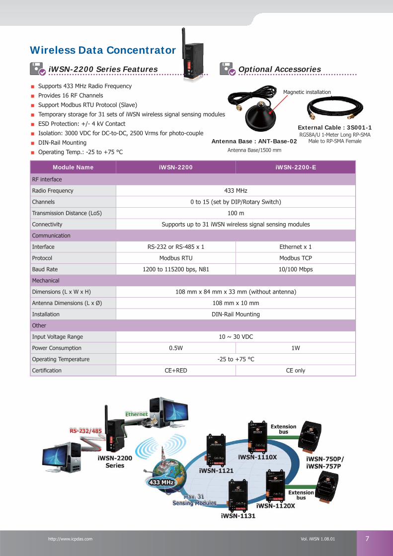
Wireless Data Concentrator
iWSN-2200 Series Features Optional Accessories
Module Name iWSN-2200 iWSN-2200-E
RF interface
Radio Frequency 433 MHz
Channels 0 to 15 (set by DIP/Rotary Switch)
Transmission Distance (LoS) 100 m
Connectivity Supports up to 31 iWSN wireless signal sensing modules
Communication
Interface RS-232 or RS-485 x 1 Ethernet x 1
Protocol Modbus RTU Modbus TCP
Baud Rate 1200 to 115200 bps, N81 10/100 Mbps
Mechanical
Dimensions (L x W x H) 108 mm x 84 mm x 33 mm (without antenna)
Antenna Dimensions (L x Ø) 108 mm x 10 mm
Installation DIN-Rail Mounting
Other
Input Voltage Range 10 ~ 30 VDC
Power Consumption 0.5W 1W
Operating Temperature -25 to +75 °C
Certifi cation CE+RED CE only
Supports 433 MHz Radio Frequency
Provides 16 RF Channels
Support Modbus RTU Protocol (Slave)
Temporary storage for 31 sets of iWSN wireless signal sensing modules
ESD Protection: +/- 4 kV Contact
Isolation: 3000 VDC for DC-to-DC, 2500 Vrms for photo-couple
DIN-Rail Mounting
Operating Temp.: -25 to +75 °C
Antenna Base : ANT-Base-02Antenna Base/1500 mm
External Cable : 3S001-1RG58A/U 1-Meter Long RP-SMA
Male to RP-SMA Female
Magnetic installation
8 ICP DAS CO., LTD. Professional Provider of High Quality Industrial Computer Products and Data Acquisition Systems Vol. iWSN 1.08.01
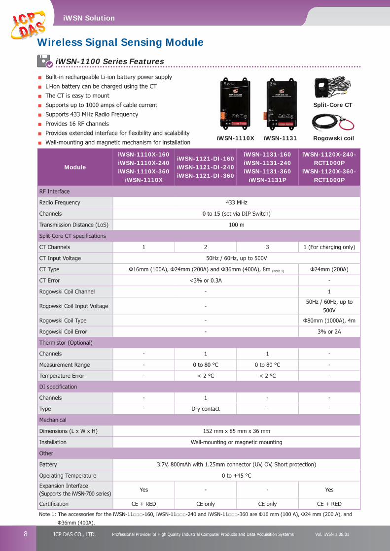
Wireless Signal Sensing Module
iWSN-1100 Series Features
Module
iWSN-1110X-160iWSN-1110X-240iWSN-1110X-360
iWSN-1110X
iWSN-1121-DI-160iWSN-1121-DI-240iWSN-1121-DI-360
iWSN-1131-160iWSN-1131-240iWSN-1131-360
iWSN-1131P
iWSN-1120X-240-RCT1000P
iWSN-1120X-360-RCT1000P
RF Interface
Radio Frequency 433 MHz
Channels 0 to 15 (set via DIP Switch)
Transmission Distance (LoS) 100 m
Split-Core CT specifi cations
CT Channels 1 2 3 1 (For charging only)
CT Input Voltage 50Hz / 60Hz, up to 500V
CT Type Φ16mm (100A), Φ24mm (200A) and Φ36mm (400A), 8m (Note 1) Φ24mm (200A)
CT Error <3% or 0.3A -
Rogowski Coil Channel - 1
Rogowski Coil Input Voltage -50Hz / 60Hz, up to
500V
Rogowski Coil Type - Φ80mm (1000A), 4m
Rogowski Coil Error - 3% or 2A
Thermistor (Optional)
Channels - 1 1 -
Measurement Range - 0 to 80 °C 0 to 80 °C -
Temperature Error - < 2 °C < 2 °C -
DI specifi cation
Channels - 1 - -
Type - Dry contact - -
Mechanical
Dimensions (L x W x H) 152 mm x 85 mm x 36 mm
Installation Wall-mounting or magnetic mounting
Other
Battery 3.7V, 800mAh with 1.25mm connector (UV, OV, Short protection)
Operating Temperature 0 to +45 °C
Expansion Interface (Supports the iWSN-700 series)
Yes - - Yes
Certifi cation CE + RED CE only CE only CE + RED
Note 1: The accessories for the iWSN-11□□□-160, iWSN-11□□□-240 and iWSN-11□□□-360 are Φ16 mm (100 A), Φ24 mm (200 A), and
Φ36mm (400A).
Built-in rechargeable Li-ion battery power supply
Li-ion battery can be charged using the CT
The CT is easy to mount
Supports up to 1000 amps of cable current
Supports 433 MHz Radio Frequency
Provides 16 RF channels
Provides extended interface for fl exibility and scalability
Wall-mounting and magnetic mechanism for installationRogowski coil
Split-Core CT
iWSN-1131iWSN-1110X
iWSN Solution
9http://www.icpdas.com Vol. iWSN 1.08.01
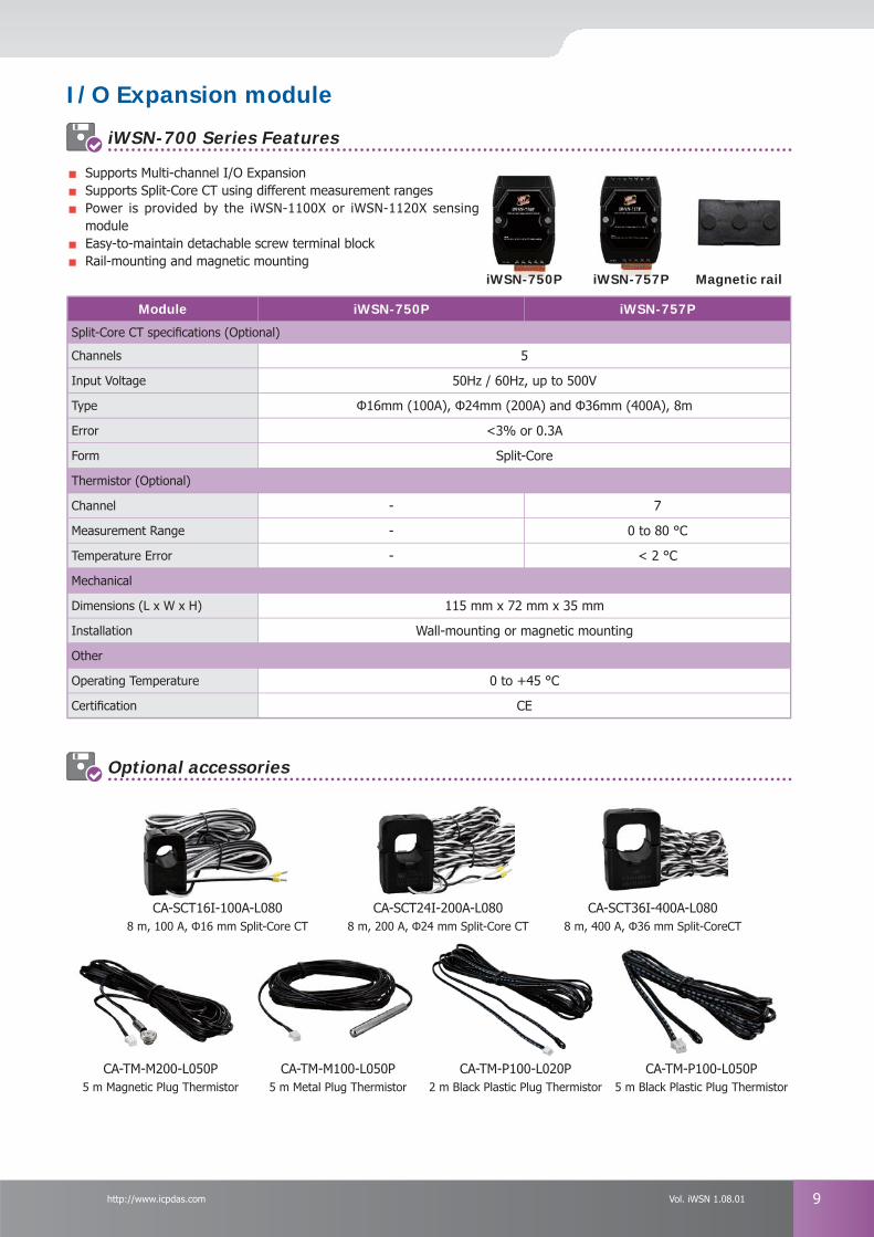
iWSN-700 Series Features
Module iWSN-750P iWSN-757P
Split-Core CT specifi cations (Optional)
Channels 5
Input Voltage 50Hz / 60Hz, up to 500V
Type Φ16mm (100A), Φ24mm (200A) and Φ36mm (400A), 8m
Error <3% or 0.3A
Form Split-Core
Thermistor (Optional)
Channel - 7
Measurement Range - 0 to 80 °C
Temperature Error - < 2 °C
Mechanical
Dimensions (L x W x H) 115 mm x 72 mm x 35 mm
Installation Wall-mounting or magnetic mounting
Other
Operating Temperature 0 to +45 °C
Certifi cation CE
I/O Expansion module
Optional accessories
Magnetic railiWSN-750P iWSN-757P
CA-TM-P100-L020P2 m Black Plastic Plug Thermistor
CA-TM-P100-L050P5 m Black Plastic Plug Thermistor
CA-TM-M100-L050P5 m Metal Plug Thermistor
CA-TM-M200-L050P5 m Magnetic Plug Thermistor
CA-SCT16I-100A-L0808 m, 100 A, Φ16 mm Split-Core CT
CA-SCT36I-400A-L0808 m, 400 A, Φ36 mm Split-CoreCT
CA-SCT24I-200A-L0808 m, 200 A, Φ24 mm Split-Core CT
Supports Multi-channel I/O Expansion Supports Split-Core CT using different measurement ranges Power is provided by the iWSN-1100X or iWSN-1120X sensing module Easy-to-maintain detachable screw terminal block Rail-mounting and magnetic mounting


![Indian Express [0918]](https://img.pdfslide.us/doc/110x75/54fe94644a7959b8508b4709/indian-express-0918.jpg)