Embed Size (px)
Citation preview
8/8/2019 iwisa09p405
http://slidepdf.com/reader/full/iwisa09p405 1/4
8/8/2019 iwisa09p405
http://slidepdf.com/reader/full/iwisa09p405 2/4
displacement stiffness matrix, and its stiffness matrix is
simpler. At the same time, TL method can used to solve
the problems of moderate rotation, but the UL method
can get accurate results even to large rotation problem
under the appropriate load step[1]. Therefore, the UL
method is applied in this paper to distribute structuralnonlinear.
C. Element Stiffness Matrixes for Bar Unit Based on the
Material Nonlinearity and Geometric Nonlinearity
There is derivation of element stiffness matrixe for bar
unit in Ref. [3] with the consideration of geometric
nonlinearity.
t t t
L N K K K (1)
t T t
t V L L T L
K B D B dV (2)
t t T T t L T N N T LV N
t T
t V N T N
K B D B B D B dV
B D B dV
(3)
Where: t
L K is linear stiffness matrixe, and t
N K
is nonlinear stiffness matrixe. L
B is linear strain matrix,
and N
B is nonlinear strain matrix. T
D is linear
elastic matrix.
According to Ref. [6], uilibrium equation described by
geometric nonlinearity holds even for bi-nonlinear
problem if the linear elastic matrix T
D is replaced by
elastic plastic matrix ep
T D in rigidity matrix.
Furthermore, elastic plastic matrix can be regard as an
superposition of elastic matrix and plastic matrix, and the
following expressions are valid.
t t T p ept V L L T L
t T t pt V L L T L
K B D B dV
K B D B dV
(4)
t t p T T ep ep
t L T N N T LV N
t T ept V N T N
t T pt V N L T N
t T T p p
t N T L N T N V
B D B B D B
t
B D B B D B
K dV
B D B dV
K B D B dV
dV
(5)
Where:p
T D is plastic matrix, and its expression as
following,
T
p T T
T T
T
D f f D
D h f D f
. Here
is material constant, and h is plastic modulus.
T
y xy yz x zx z
f f f f f f f
.
Therefore
element stiffness matrixes for bar unit withthe consideration of bi-nonlinearity which is based on UL
method can be expressed as:
t t t p p p
L N
t t t
L N P
K K K
K K K
(6)
t t T T p pt V L T L L T N P
t T T p pt V N T L N T N
K B D B B D B dV
B D B B D B dV
(7)
Here t
P K is plastic correction matrix.
The expression of beam element stiffness matrixes
with the consideration of bi-nonlinearity can be deduced
in a similar way therefore will not be discussed here.
D. Treatment of Nonlinear Space Cable Unit
Cable is a kind of flexible construction whose change
in length includes elastic stretching and sag fix under the
effect of deadweight and tension. The stay guy of guyed
transmission tower has the characteristic of high tension
and small span. According to Ref. [5], the authors use
Ernst formula to modify slack and sag of the cable on the basis of bar unit, that is to modify the elastic modulus of
cable unit.Cable units only endure axial tensile stress. In the
calculation process, if the internal force of cable unit is
negative, making it zero, and removing the contribution
of cable unit stiffness on the entire structure.
E. Condensation of Element Degrees of Freedom and Coordinate Transformation of Characteristic Matrix
There are three types of element existing in the finite
element model of guyed transmission tower, includingordinary beam element, bar element and cable element,
and meanwhile in the model there is beam element with
one rigid joint and one hinged joint. So it should use a
uniform expression form for stiffness matrix of each
element before assembling global stiffness matrix.
The first case: condensation of rod-cable element
degrees of freedom.
Each node of beam element has three linedisplacements and three angular displacements, and each
node of bar element only has three line displacements,
then it just need to expand the rod-cable element stiffness
matrix to 12 * 12 matrix, compared with the beamelement stiffness matrix, adding zero elements in the
rows and columns related with angular displacement to
ensure them maintain the same order of the elementstiffness matrix.
The second case: condensation of degrees of freedom
of beam element with one rigid joint and one hinged joint.
406
8/8/2019 iwisa09p405
http://slidepdf.com/reader/full/iwisa09p405 3/4
Assumed that beam element with node i (rigid) and j(hinged), the balance equation of the beam element is:
11 12 13 14
21 22 23 24
31 32 33 34
41 42 43 44
i i
i i
j j
j j
u N k k k k
M k k k k
u N k k k k
k k k k M
(8)
Where:mn
k (m, n = 1-4) is 3 * 3 matrix (partitioning of
element stiffness matrix);i
u ,i
,i
N andi
M is
respectively line displacement vector, angular
displacement vector, node internal force vector and
moment vector of node i; j
u , j
, j
N and j
M is
respectively line displacement vector, angular
displacement vector, node internal force vector and
moment vector of node j.
jM =0then the forth formula of (8) shows
1
44 41 42 43 j i i jk k u k k u
(9)
We can see from (9): hinged end angular displacement
of beam element is not necessarily zero, and it is related
with stiffness matrix, node line displacement and angular displacement of the other side.
Substituting (9) into the first three formulas of (8), it
can get equilibrium equations of beam element with one
rigid joint and one hinged joint after condensation:
1 1 111 14 44 41 12 14 44 42 13 14 44 43
1 1 1
21 24 44 41 22 24 44 42 23 24 44 43
1 1 1
31 34 44 41 32 34 44 42 33 34 44 43
i
i
j
i
i
j
k k k k k k k k k k k k u
k k k k k k k k k k k k
uk k k k k k k k k k k k
N
M
N
(10)
Adding zero elements in the related rows and columns
by condensation in the beam element stiffness matrix,so
as to maintain the original order of the element stiffness
matrix.After condensation , all element stiffness matrixes
become 12 * 12 matrix, and then using the coordinate
transformation matrix 0 , transform the element
characteristic matrix in the local coordinate to the systemglobal coordinate, at last assemble the stiffness matrix,
displacement vector and load vector.
F. Establishing and Solving of Nonlinear Finite Element
Equilibrium Equations
Under initial prestress state, the guyed transmission
tower reach balance state of self-stress by the role of
prestress and gravity. In this process, based on ULmethod, in the overall coordinate system, the load stepfrom time t to , the non-linear incremental
equilibrium equations of the structure is:
t t t t
K d u R F
(11)
Where: t
K is the total tangent stiffness matrix of the
structure at time t , d u is the nodes displacement
increment vector from time t to t+t , t t
R
is the node
load vector at time t+t , t
F is the equivalent nodes
load vector at time t .According to Ref. [3], using Newton-Raphson iterative
method to calculate is better to reflect the merits of UL,
so this method is adopted in this paper. The influence that
deformation has on structural stiffness in the process of
finite element calculate is treated with large deformation
effects and stress stiffening effects.
. CALCULATING EXAMPLE
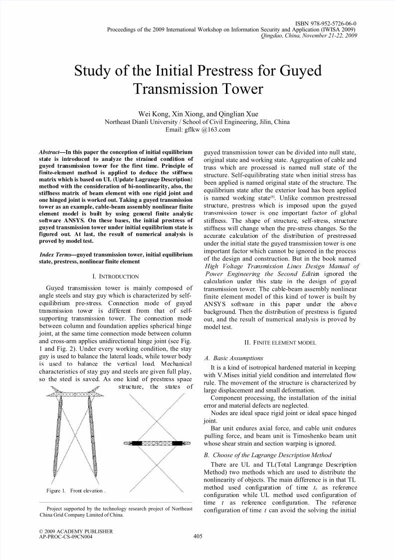
Taking LM21 (33m) guyed tower in DongChangHa
transmission line as an example, establish a finite element
model. Principals and diaphragm were simulated byBeam189 in the model, auxiliary bars are simulated by
Link8, and stay guys are simulated by Link10. The pre-
stress of stay guys was carried out by using the method of
initial strain simulation, this method can consider thecontribution of cable element stiffness on global stiffness
of the structure. Furthermore, it can solve two problems:
balance of node prestress and the deformation harmony
of cable. Hinge between cross arm and main column was
carried out by mans of freedom degree coupling.
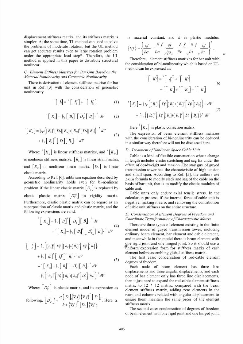
The table below lists the numerical analysis andmeasured results comparison of axial force (see table ).
. CONCLUSION
From Table , we can see most of the numerical
analysis results are larger than the measured values. The
reason for this error is mainly due to the straining of the
bars can not be measured under the effect of deadweight.
TABLE I.COMPARISON OF NUMERICAL ANALYSIS AND TEST RESULTS
Measuring point
number
Value of Numerical
Analysis(MPa)
Measuredvalue
(MPa)Error Remarks
1 37.99 40.11 0.05 Iron274
2 32.37 24.68 -0.31
3 32.38 24.5 -0.32Iron236
4 24.57 22.19 -0.11
5 24.94 22.47 -0.11Iron272
6 33.21 32.74 -0.01 Iron153
7 12.89 12.26 -0.05
8 14.34 13.83 -0.04
9 13.45 13 -0.03
10 13.87 12.94 -0.07
Iron301-303
407
8/8/2019 iwisa09p405
http://slidepdf.com/reader/full/iwisa09p405 4/4
Table shows that some member bars have relatively
big errors. The reason is in that all nodes in numerical
analysis are ideal while allowable space has been shown
between node and bolt in practical engineering. For this
reason, element 274 sustains pulling force which is
applied by stay guy in the process of stretch-draw. After this element is out of shape, the member bars connected
with 274 come into effect. This also explains why the
element 274 which is satisfied with the designrequirements produces obvious bending deflection.
Furthermore, detail design of member bars which
connected with stay guy must be taken into consideration
during the design of prestress space steel structure.
R EFERENCES
[1] Dong Chen, and Cimian Zhu, “Feasibility of finite elementmethods for the annlysis of geometrically nonlinear
trusses,” Building Science Research of Sichuan, Chengdu,China, vol. 26, No. 3, September, 2000.
[2] Hongzhou Deng, and Xiaoming Chen, “Experimentalstudy on model of jiangyin long span transmission tower,” Journal of Buiding Structures, Beijing, China, vol. 22, No.6, December, 2001.
[3] Zhihong Zhang, “Theoretical research on large-span tensile
spatial structures composed of cables, bars and beams,”doctoral dissertation, Zhe Jiang University, Hangzhou,China, 2003.
[4] Zuyan Shen, Guoqiang Li, Yiyi Chen, Qilin Zhang,
Yongfeng Luo, “Steel Structure,” China Building Industry
Press, Beijing, China, 2005.[5] Yuanpei Lin, “Cable Stayed Bridge,” China
Communications Press, Beijing, China, 2004.[6] Haojiang Ding, Fubao He, Yiquan Xie and Xing Xu,
“Finite Element Method in Elasticity and Plasticity,”Machinery Industry Press, Beijing, China, 1984.
[7] Xucheng Wang, “Finite Element Method,” TsinghuaUniversity Press, Beijing, China, 2003.
[8] Mingxiang Chen, “Elasticity and Plasticity,” Science Press, Beijing, China, 2007.
[9] Xinmin Wang, “Numerical Analysis of EngineeringStructure Based on ANSYS,” China Communications
Press, Beijing, China, 2007.
408


