Embed Size (px)
Citation preview
IWAKI AMERICA MDF-L SERIES
MAGNETIC DRIVE PUMP INSTRUCTION MANUAL
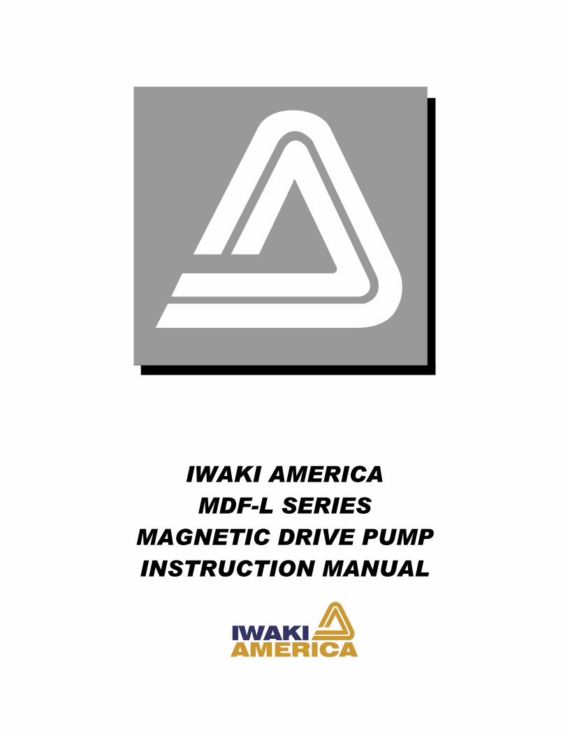
MDF-L SERIES INSTRUCTION MANUAL Table of Contents
1 UNPACKING AND INSPECTION................................................................................................................... 1
2 MODEL IDENTIFICATION GUIDE .............................................................................................................. 2 MODEL..................................................................................................................................................................... 2
3 SPECIFICATIONS............................................................................................................................................. 3 � MATERIALS OF MAIN COMPONENTS..................................................................................................................... 4
4 HANDLING INSTRUCTIONS ......................................................................................................................... 5
5 INSTALLATION, PIPING, AND WIRING..................................................................................................... 8 � INSTALLATION POSITION...................................................................................................................................... 8 � INSTALLATION ..................................................................................................................................................... 8 � PIPING................................................................................................................................................................ 9 � SUCTION PIPING ................................................................................................................................................. 9 � DISCHARGE PIPING........................................................................................................................................... 11 ��WIRING.............................................................................................................................................................. 12
6 OPERATION .................................................................................................................................................... 13 � NOTES ON OPERATION ...................................................................................................................................... 13 � START-UP PREPARATION................................................................................................................................... 14 � STARTING OPERATION STEPS ............................................................................................................................. 15 � STOPPING OPERATION STEPS ............................................................................................................................ 16
7 MAINTENANCE AND INSPECTION........................................................................................................... 16 � DAILY INSPECTION .......................................................................................................................................... 16 � PERIODIC INSPECTION ...................................................................................................................................... 17 � REPLACEMENT TOLERANCE CHART ................................................................................................................... 19 � CHECKING WEAR OF CONICAL THRUST BUSHING .............................................................................................. 20
8 TROUBLESHOOTING ................................................................................................................................... 22
9 PARTS DESCRIPTION AND EXPLODED VIEW ...................................................................................... 24
10 DISASSEMBLY AND ASSEMBLY OF PUMP......................................................................................... 26 � DISASSEMBLY.................................................................................................................................................... 26 � REPLACEMENT OF BUSHING, OUTBOARD THRUST COLLAR AND SHAFT............................................................... 28 � REASSEMBLY ..................................................................................................................................................... 30
11 SPARE PARTS ............................................................................................................................................. 32
12 DIMENSIONS AND WEIGHTS ................................................................................................................. 33
This product is protected by patents. 180119 Rev. G Jan 2006
1
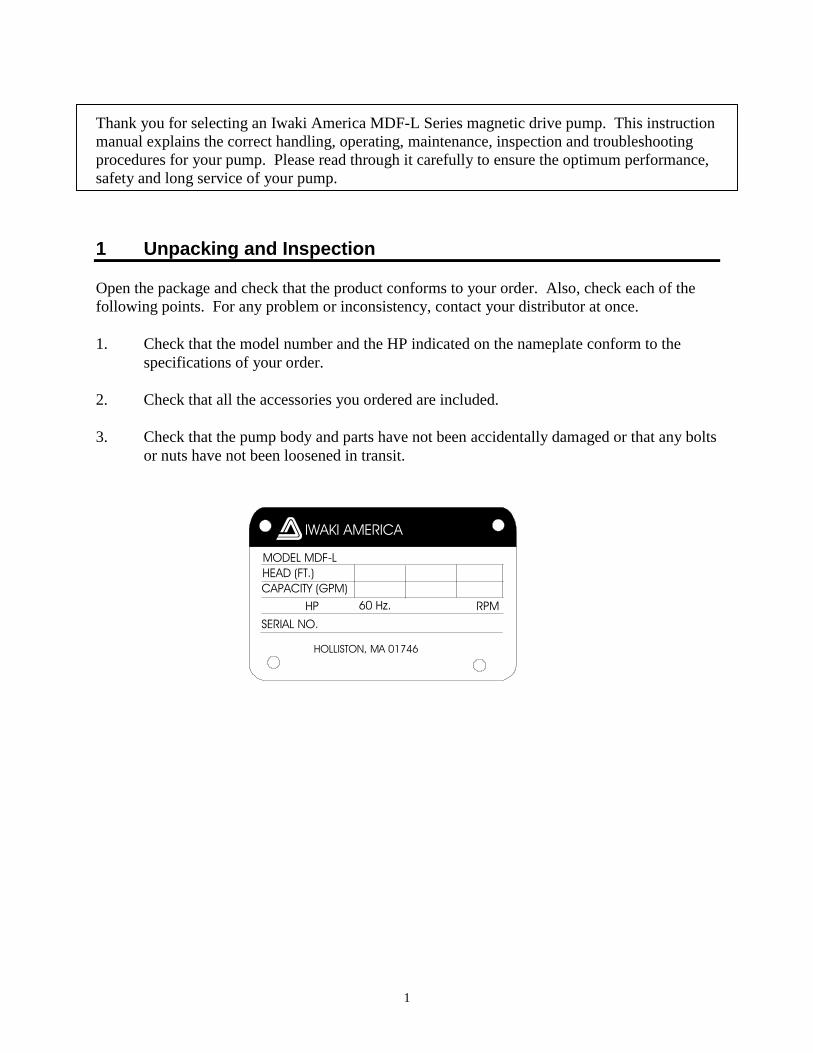
Thank you for selecting an Iwaki America MDF-L Series magnetic drive pump. This instruction manual explains the correct handling, operating, maintenance, inspection and troubleshooting procedures for your pump. Please read through it carefully to ensure the optimum performance, safety and long service of your pump. 1 Unpacking and Inspection Open the package and check that the product conforms to your order. Also, check each of the following points. For any problem or inconsistency, contact your distributor at once. 1. Check that the model number and the HP indicated on the nameplate conform to the
specifications of your order. 2. Check that all the accessories you ordered are included. 3. Check that the pump body and parts have not been accidentally damaged or that any bolts
or nuts have not been loosened in transit.
MODEL MDF-LHEAD (FT.) CAPACITY (GPM)
SERIAL NO. HOLLISTON, MA 01746
IWAKI AMERICA
HP 60 Hz. RPM
2
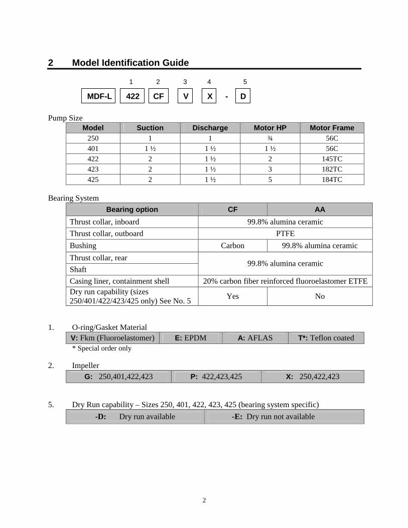
2 Model Identification Guide 1 2 3 4 5
MDF-L 422 CF V X - D Pump Size
Model Suction Discharge Motor HP Motor Frame 250 1 1 ¾ 56C 401 1 ½ 1 ½ 1 ½ 56C 422 2 1 ½ 2 145TC 423 2 1 ½ 3 182TC 425 2 1 ½ 5 184TC
Bearing System
Bearing option CF AA Thrust collar, inboard 99.8% alumina ceramic Thrust collar, outboard PTFE Bushing Carbon 99.8% alumina ceramic Thrust collar, rear Shaft
99.8% alumina ceramic
Casing liner, containment shell 20% carbon fiber reinforced fluoroelastomer ETFE Dry run capability (sizes 250/401/422/423/425 only) See No. 5 Yes No
1. O-ring/Gasket Material
V: Fkm (Fluoroelastomer) E: EPDM A: AFLAS T*: Teflon coated * Special order only 2. Impeller
G: 250,401,422,423 P: 422,423,425 X: 250,422,423 5. Dry Run capability – Sizes 250, 401, 422, 423, 425 (bearing system specific)
-D: Dry run available -E: Dry run not available
3
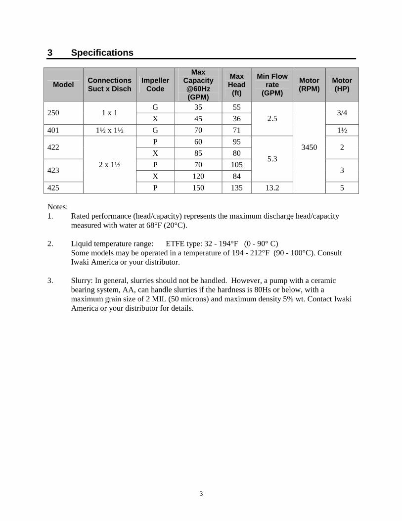
3 Specifications
Model Connections Suct x Disch
Impeller Code
Max Capacity @60Hz (GPM)
Max Head (ft)
Min Flow rate
(GPM) Motor (RPM)
Motor (HP)
G 35 55 250 1 x 1
X 45 36 3/4
401 1½ x 1½ G 70 71 2.5
1½ P 60 95
422 X 85 80
2
P 70 105 423
X 120 84
5.3 3
425
2 x 1½
P 150 135 13.2
3450
5 Notes: 1. Rated performance (head/capacity) represents the maximum discharge head/capacity
measured with water at 68°F (20°C). 2. Liquid temperature range: ETFE type: 32 - 194°F (0 - 90° C) Some models may be operated in a temperature of 194 - 212°F (90 - 100°C). Consult
Iwaki America or your distributor. 3. Slurry: In general, slurries should not be handled. However, a pump with a ceramic
bearing system, AA, can handle slurries if the hardness is 80Hs or below, with a maximum grain size of 2 MIL (50 microns) and maximum density 5% wt. Contact Iwaki America or your distributor for details.
4
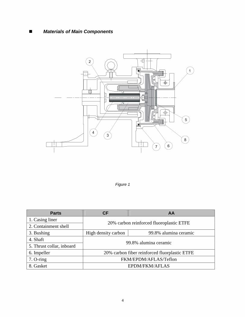
�� Materials of Main Components
Figure 1
Parts CF AA 1. Casing liner 2. Containment shell
20% carbon reinforced fluoroplastic ETFE
3. Bushing High density carbon 99.8% alumina ceramic 4. Shaft 5. Thrust collar, inboard
99.8% alumina ceramic
6. Impeller 20% carbon fiber reinforced fluorplastic ETFE 7. O-ring FKM/EPDM/AFLAS/Teflon 8. Gasket EPDM/FKM/AFLAS
5
4 Handling Instructions 1. Do not operate the pump dry The sliding parts used in the MDF-L series pump are lubricated and cooled by the fluid
being pumped. Never operate the pump dry or with the valves on the suction side closed. Otherwise, the inside of the pump will be damaged. If the pump is unavoidably or accidentally operated dry, with no obvious damage, allow the pump to cool down for a minimum of one hour before attempting to restart. Do not allow fluid to enter the pump cavity until the pump has cooled down. Sudden or rapid cooling of the pump may cause damage to the ceramic bushing system. A dry run monitoring device (current or power sensor) is recommended for the prevention of damage when dry run operation is likely.
"-D" Models Some MDF-L models in the 250, 401, 422, 423 and 425 sizes are designed to tolerate
brief or intermittent dry run operation, they are identified by a "-D" at the end of the model number. These models can tolerate dry run conditions for up to one hour. Longer dry run periods, or frequent dry running may result in premature wear of the bushing and shaft. This can rapidly affect the standard clearances of the rotating elements inside the pump. These pumps are designed to reduce the likelihood of cracking resulting from sudden cooling with liquid immediately after dry run operation. However, to ensure that this does not occur, Iwaki America recommends that the pump be allowed to cool for at least 20 minutes after dry running before introducing fluid again.
"-E" Models Pump models with a suffix '-E' have a similar bushing system construction to '-D'
models. However, they are not rated for dry run operation. 2. Starting and Stopping Pay close attention to the following points to avoid water hammer upon starting and
stopping of pump operation. Extra attention is required when the discharge piping is very long.
Starting Prior to starting the pump, make sure that the power is turned off. Then carry out priming
to fill the pump cavity with liquid. Next, close the valves on the discharge side. Now you can turn the power on and start up
the pump. When the pump has reached full speed and line pressure is stable, the discharge valve can be opened to the desired pressure setting.
Caution! If the pump is operated with air remaining within the pump
cavity, pitting, cracking, or breakage of the bushing and/or thrust collar may occur, causing damage to the pump.
6
Stopping When stopping the pump, first close the discharge valve gradually. When it is completely closed,
turn off the power switch so that the pump stops. Never stop the pump suddenly by quickly closing a valve (i.e., solenoid or hydraulic valves).
Caution! Quick valve closure may cause water hammer which can
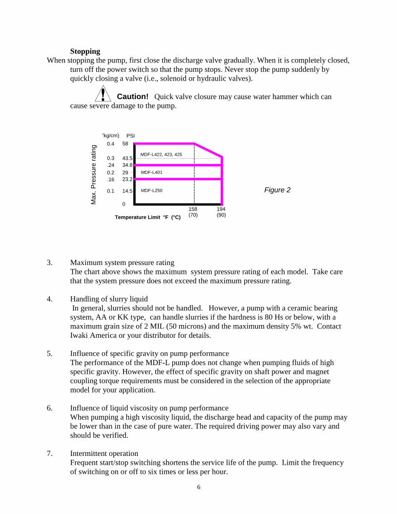
cause severe damage to the pump. 3. Maximum system pressure rating The chart above shows the maximum system pressure rating of each model. Take care
that the system pressure does not exceed the maximum pressure rating. 4. Handling of slurry liquid In general, slurries should not be handled. However, a pump with a ceramic bearing
system, AA or KK type, can handle slurries if the hardness is 80 Hs or below, with a maximum grain size of 2 MIL (50 microns) and the maximum density 5% wt. Contact Iwaki America or your distributor for details.
5. Influence of specific gravity on pump performance The performance of the MDF-L pump does not change when pumping fluids of high
specific gravity. However, the effect of specific gravity on shaft power and magnet coupling torque requirements must be considered in the selection of the appropriate model for your application.
6. Influence of liquid viscosity on pump performance When pumping a high viscosity liquid, the discharge head and capacity of the pump may
be lower than in the case of pure water. The required driving power may also vary and should be verified.
7. Intermittent operation Frequent start/stop switching shortens the service life of the pump. Limit the frequency
of switching on or off to six times or less per hour.
PSI (kg/cm)2
0.4 58
43.5 0.3 .24
29 0.2 .16
14.5 0.1
Temperature Limit °F (°C) 158(70)
194(90)
34.8
23.2
0
MDF-L422, 423, 425
MDF-L401
MDF-L250 Figure 2
Max
. Pre
ssur
e ra
ting
7
8. Effects of temperature The pump itself may not suffer a change in performance due to temperature fluctuation.
However, the liquid may change in terms of viscosity, vapor pressure, and corrosive properties. Pay special attention to changes in liquid characteristics as a result of temperature fluctuation.
Liquid temperature range: ETFE type: 32 - 194° F (0 - 90°C) Ambient temperature range: 32 - 104° F (0 - 40°C) Refer to corrosion resistance tables for the recommended temperature range for various types of
liquids. In case of any questions, contact Iwaki America or your distributor to determine if operation is feasible.
Some types of pumps can be operated in the fluid temperature range of 194-212°F (90-100°C).
For details contact Iwaki America or your distributor. 9. Separation of magnet coupling (decoupling) If the magnet coupling should disconnect, stop the pump immediately. If operation is
continued, the torque rating of the coupling will be permanently reduced. 10. Operation within range of bell-shaped head/capacity curve In the case of a pump which generates a bell-shaped capacity curve in a low-flow range,
do not operate the pump in the section where the line ascends. (Refer to the standard performance curve to verify the head/capacity). If the rightward ascending section of the head/capacity curve is part of the pump operation specifications, design the piping by observing the following points:
1. The discharge piping should have no water tank or air trap,
2. The discharge quantity must be adjusted by a valve which is installed close to the discharge port of the pump.
8
5 Installation, Piping, and Wiring �� Installation Position 1. Install the pump as close to the suction tank as possible (flooded suction). If the suction
port of the pump is positioned higher than the suction tank (suction lift), be sure to arrange a foot valve in the suction pipe. The lifting capability depends upon the liquid properties, temperature, and length of suction piping. For details, consult Iwaki America or your distributor.
2. The pump can be installed indoors or outdoors. However, there should be sufficient
space around the pump to enable efficient and easy maintenance. �� Installation 1. The pump anchoring area must be greater than the area of the pump baseplate. If the
anchoring area is not large enough, the baseplate may be damaged due to the concentration of loads placed on it.
2. Set the pump baseplate on a concrete foundation and fasten the anchor bolts tightly to
prevent the pump from vibrating during operation. A sturdy metal (or reinforced) skid or platform is also an acceptable mounting surface.
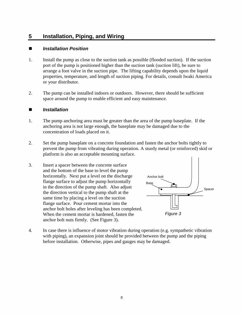
3. Insert a spacer between the concrete surface
and the bottom of the base to level the pump horizontally. Next put a level on the discharge flange surface to adjust the pump horizontally in the direction of the pump shaft. Also adjust
the direction vertical to the pump shaft at the same time by placing a level on the suction flange surface. Pour cement mortar into the anchor bolt holes after leveling has been completed. When the cement mortar is hardened, fasten the anchor bolt nuts firmly. (See Figure 3).
4. In case there is influence of motor vibration during operation (e.g. sympathetic vibration
with piping), an expansion joint should be provided between the pump and the piping before installation. Otherwise, pipes and gauges may be damaged.
Base
Anchor bolt
Spacer
Figure 3
9
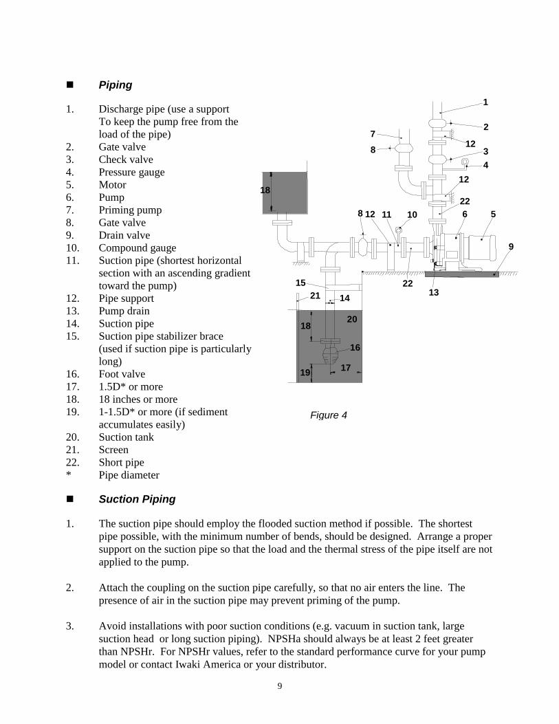
�� Piping 1. Discharge pipe (use a support
To keep the pump free from the load of the pipe)
2. Gate valve 3. Check valve 4. Pressure gauge 5. Motor 6. Pump 7. Priming pump 8. Gate valve 9. Drain valve 10. Compound gauge 11. Suction pipe (shortest horizontal
section with an ascending gradient toward the pump)
12. Pipe support 13. Pump drain 14. Suction pipe 15. Suction pipe stabilizer brace
(used if suction pipe is particularly long)
16. Foot valve 17. 1.5D* or more 18. 18 inches or more 19. 1-1.5D* or more (if sediment
accumulates easily) 20. Suction tank 21. Screen 22. Short pipe * Pipe diameter �� Suction Piping 1. The suction pipe should employ the flooded suction method if possible. The shortest
pipe possible, with the minimum number of bends, should be designed. Arrange a proper support on the suction pipe so that the load and the thermal stress of the pipe itself are not applied to the pump.
2. Attach the coupling on the suction pipe carefully, so that no air enters the line. The
presence of air in the suction pipe may prevent priming of the pump. 3. Avoid installations with poor suction conditions (e.g. vacuum in suction tank, large
suction head or long suction piping). NPSHa should always be at least 2 feet greater than NPSHr. For NPSHr values, refer to the standard performance curve for your pump model or contact Iwaki America or your distributor.
19
18
2115
14
20
16
17
18
87
1
2
12
12
101112822
2213
34
6 5
9
Figure 4
10
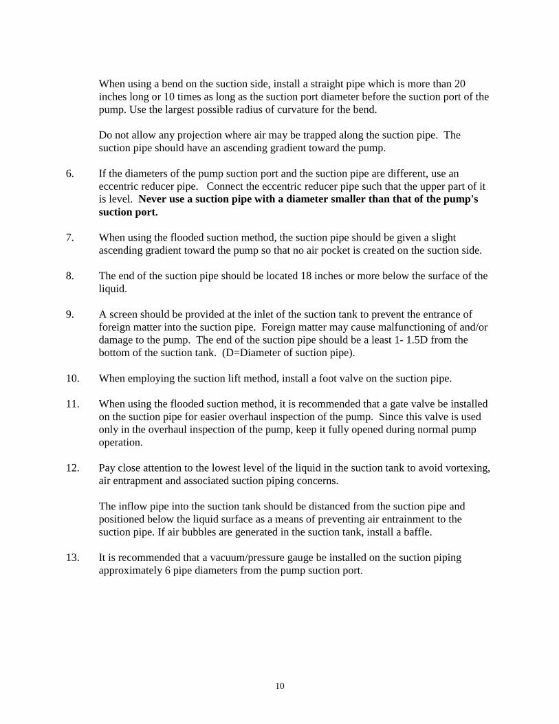
When using a bend on the suction side, install a straight pipe which is more than 20 inches long or 10 times as long as the suction port diameter before the suction port of the pump. Use the largest possible radius of curvature for the bend.
Do not allow any projection where air may be trapped along the suction pipe. The suction pipe should have an ascending gradient toward the pump.
6. If the diameters of the pump suction port and the suction pipe are different, use an
eccentric reducer pipe. Connect the eccentric reducer pipe such that the upper part of it is level. Never use a suction pipe with a diameter smaller than that of the pump's suction port.
7. When using the flooded suction method, the suction pipe should be given a slight
ascending gradient toward the pump so that no air pocket is created on the suction side. 8. The end of the suction pipe should be located 18 inches or more below the surface of the
liquid. 9. A screen should be provided at the inlet of the suction tank to prevent the entrance of
foreign matter into the suction pipe. Foreign matter may cause malfunctioning of and/or damage to the pump. The end of the suction pipe should be a least 1- 1.5D from the bottom of the suction tank. (D=Diameter of suction pipe).
10. When employing the suction lift method, install a foot valve on the suction pipe. 11. When using the flooded suction method, it is recommended that a gate valve be installed
on the suction pipe for easier overhaul inspection of the pump. Since this valve is used only in the overhaul inspection of the pump, keep it fully opened during normal pump operation.
12. Pay close attention to the lowest level of the liquid in the suction tank to avoid vortexing,
air entrapment and associated suction piping concerns. The inflow pipe into the suction tank should be distanced from the suction pipe and
positioned below the liquid surface as a means of preventing air entrainment to the suction pipe. If air bubbles are generated in the suction tank, install a baffle.
13. It is recommended that a vacuum/pressure gauge be installed on the suction piping
approximately 6 pipe diameters from the pump suction port.
11
�� Discharge Piping 1. Use proper pipe supports so that the weight of the piping does not load the pump nozzle. 2. If a method other than flooded suction is used, install a special pipe for priming. 3. If the piping is very long, its diameter should be determined by calculating the piping
resistance. Otherwise, the specified performance may not be obtained due to increased piping resistance.
4. A check valve should be installed if any of the following conditions exists in the piping:
• The discharge piping is very long. • The discharge head is 50 feet or more. • The end of the discharge pipe is located 30 feet higher than the surface of the
suction tank. • Several pumps are connected in parallel with the same piping.
12
5. The installation of a gate valve on the discharge pipe is recommended for the adjustment of discharge quantity and for the prevention of motor overload. When installing both a check valve and a gate valve, the check valve should be positioned between the pump and the gate valve.
6. A pressure gauge must be installed on the discharge piping, prior to the gate valve. 7. An air bleeding valve should be installed if the discharge pipe is very long in the
horizontal direction. 8. A drain valve should be installed for the drainage of liquid if there is a chance that the
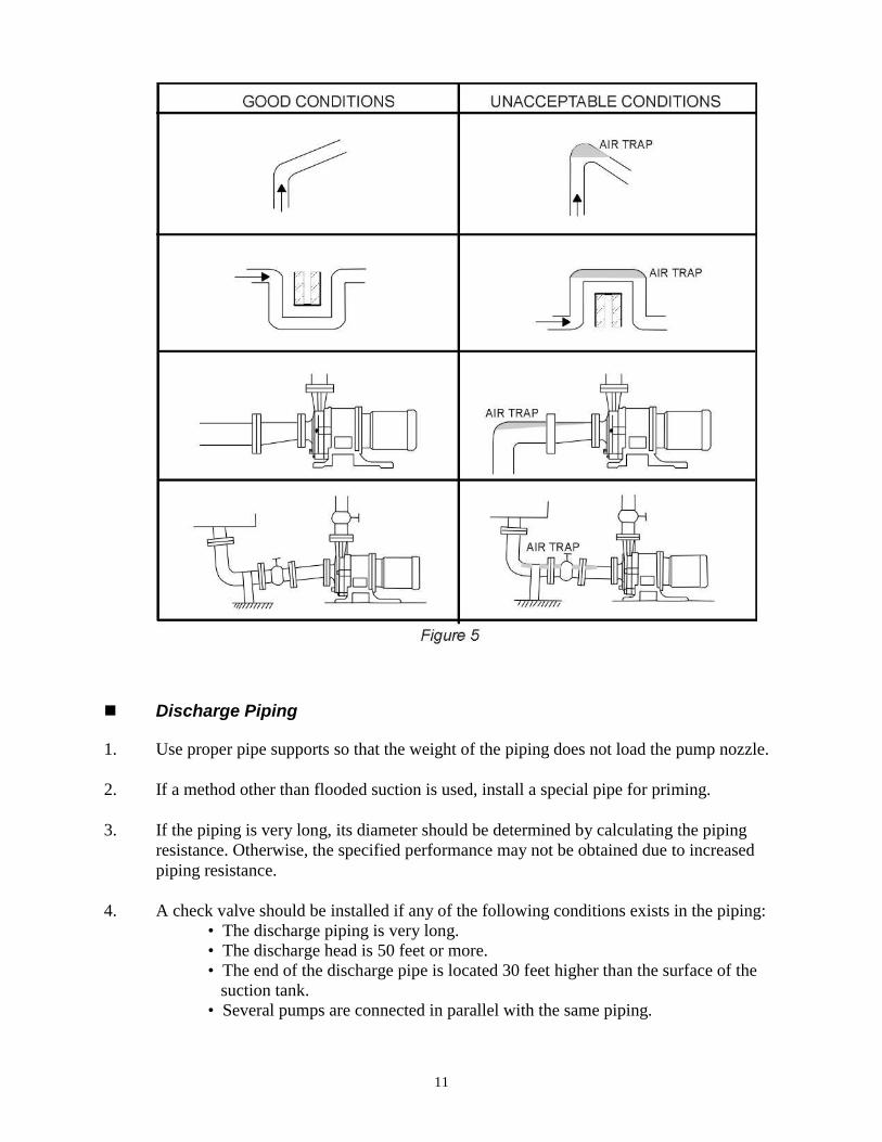
liquid in the discharge pipe will freeze. �� Wiring
Use appropriate wiring materials, follow the instruction manual for the motor and abide by the local and national electrical codes. In addition, follow the instructions given below: 1. Use a motor contactor that conforms to the specifications (voltage, current, etc.) of the
pump motor. 2. If the pump is installed outdoors, use waterproof wiring to protect the switches from
rainwater and moisture. 3. The motor contactor and push button should be installed a reasonable distance from the
pump.
MC
M
OLR
MC ON
OFF
R S TPOWER
PUSHBUTTON
M
TR AR MCMC
R S TPOWER
MCB
OLR
OLR
PBS
OFF
ARTRON
MCY
ARMCY
MC
PUSHBUTTON
TR
AR
MC
Y
UVW
X Y Z
For ½ - 7½ HP motor: For 10-20 HP motor:
MMCONOFFOLR
MOTORELECTROMAGNETIC SWITCH
OVERLOAD RELAY
PUSH BUTTON
MONOFFMCMCBMCYOLRTRAR
MOTOR
ELECTROMAGNETIC CONTACTORNONFUSE BREAKERELECTROMAGNETIC CONTACTOROVERLOAD RELAYTIMERAUXILIARY RELAY
PUSH BUTTON
Figure 6
13
4. For pumps using a motor of 10 HP or larger, use of a soft start motor voltage/amperage
device is recommended.
Refer to the wiring examples shown above. (These examples do not include the installation of a dry run prevention device. Follow the instruction manual of the dry run prevention device when installing it.)
6 Operation �� Notes on Operation 1. Never operate the pump with the suction valve (gate valve) closed. Otherwise, the
internal bushing of the pump will be damaged. 2. In the event of cavitation, stop the pump immediately. 3. If the magnet coupling disconnects, stop the pump immediately. The torque rating of the
magnet coupling will be reduced if operation is continued with the coupling disconnected.
4. Liquid temperature fluctuation should not exceed 144o F (62°C) when starting, stopping,
and operating the pump. 5. Be sure to close the discharge valve completely prior to start-up in order to prevent water
hammer. 6. The pump should never be operated with the discharge valve closed for longer than one
minute. A resulting rise in temperature of liquid within the pump may cause damage.
In the event of a service power failure, turn off the power switch immediately and close the discharge valve.
14
�� Start-Up Preparation When operating the pump for the first time after installation, and when restarting operation after a long interval, prepare for operation as described below. 1. Thoroughly clean the inside of the piping and pump. 2. Tighten the union fittings or flange connecting bolts and baseplate installation bolts.
Check the torque of the bolts which couple the front casing and the bracket together. Proper torque is 32.5 ft-lbs.
3. Close the cocks of any pressure or vacuum gauges to prevent damage from sudden
pressure changes. Open only when taking measurements. 4. Fully open the suction gate valve and partly open the discharge valve. Discharge valve
may be adjusted after completion of priming and start-up process. 5. Use a screwdriver to rotate the motor fan and check that the fan rotates smoothly. This
also purges any residual air from in and around the impeller. 6. If using flooded suction, measure the pressure in the suction pipe to verify that the pump
is filled with liquid. 7. Run the motor momentarily to check the direction of motor rotation. The motor should
run in the direction indicated by the arrow cast on the pump casing. If the direction is reversed, exchange two wires of the three-phase power wires.
Note: All Iwaki America MDF-L series pumps rotate counter-clockwise when looking at
the suction port of the pump. Naturally, from the motor fan side, this would be viewed as clockwise.
15
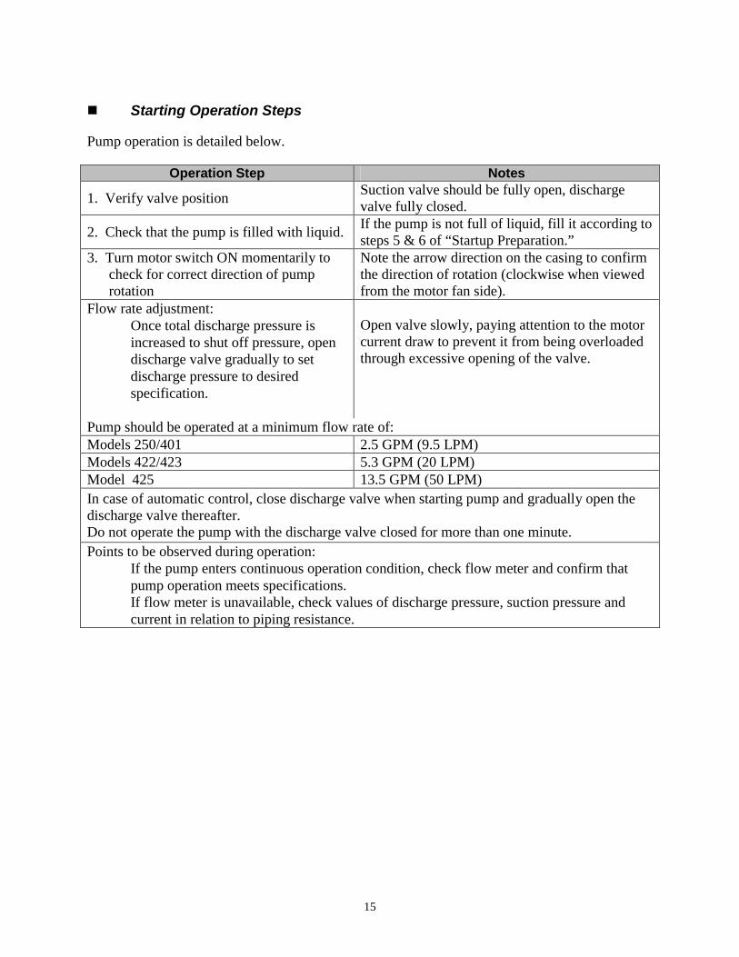
�� Starting Operation Steps Pump operation is detailed below.
Operation Step Notes
1. Verify valve position Suction valve should be fully open, discharge valve fully closed.
2. Check that the pump is filled with liquid. If the pump is not full of liquid, fill it according to steps 5 & 6 of “Startup Preparation.”
3. Turn motor switch ON momentarily to check for correct direction of pump rotation
Note the arrow direction on the casing to confirm the direction of rotation (clockwise when viewed from the motor fan side).
Flow rate adjustment: Once total discharge pressure is
increased to shut off pressure, open discharge valve gradually to set discharge pressure to desired specification.
Open valve slowly, paying attention to the motor current draw to prevent it from being overloaded through excessive opening of the valve.
Pump should be operated at a minimum flow rate of: Models 250/401 2.5 GPM (9.5 LPM) Models 422/423 5.3 GPM (20 LPM) Model 425 13.5 GPM (50 LPM) In case of automatic control, close discharge valve when starting pump and gradually open the discharge valve thereafter. Do not operate the pump with the discharge valve closed for more than one minute. Points to be observed during operation: If the pump enters continuous operation condition, check flow meter and confirm that
pump operation meets specifications. If flow meter is unavailable, check values of discharge pressure, suction pressure and
current in relation to piping resistance.
16
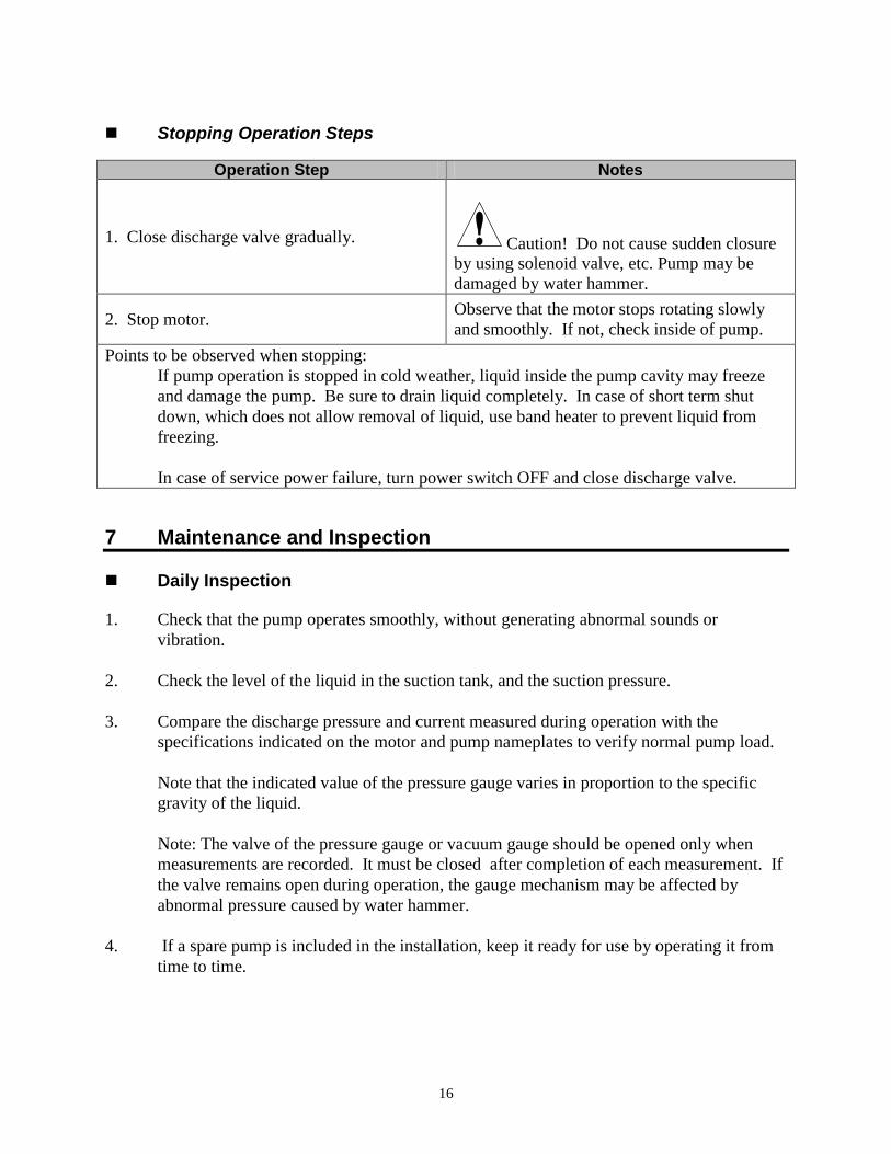
�� Stopping Operation Steps
Operation Step Notes
1. Close discharge valve gradually.
Caution! Do not cause sudden closure by using solenoid valve, etc. Pump may be damaged by water hammer.
2. Stop motor. Observe that the motor stops rotating slowly and smoothly. If not, check inside of pump.
Points to be observed when stopping: If pump operation is stopped in cold weather, liquid inside the pump cavity may freeze
and damage the pump. Be sure to drain liquid completely. In case of short term shut down, which does not allow removal of liquid, use band heater to prevent liquid from freezing.
In case of service power failure, turn power switch OFF and close discharge valve. 7 Maintenance and Inspection �� Daily Inspection 1. Check that the pump operates smoothly, without generating abnormal sounds or
vibration. 2. Check the level of the liquid in the suction tank, and the suction pressure. 3. Compare the discharge pressure and current measured during operation with the
specifications indicated on the motor and pump nameplates to verify normal pump load. Note that the indicated value of the pressure gauge varies in proportion to the specific
gravity of the liquid. Note: The valve of the pressure gauge or vacuum gauge should be opened only when
measurements are recorded. It must be closed after completion of each measurement. If the valve remains open during operation, the gauge mechanism may be affected by abnormal pressure caused by water hammer.
4. If a spare pump is included in the installation, keep it ready for use by operating it from
time to time.
17
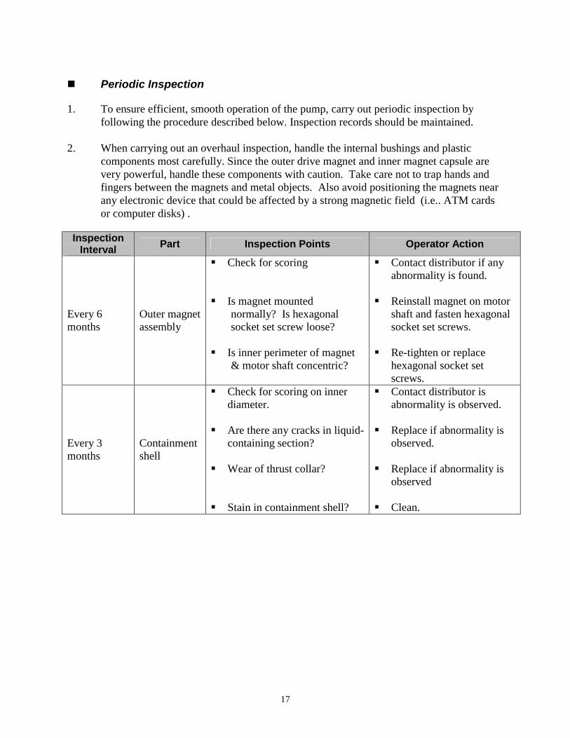
�� Periodic Inspection 1. To ensure efficient, smooth operation of the pump, carry out periodic inspection by
following the procedure described below. Inspection records should be maintained. 2. When carrying out an overhaul inspection, handle the internal bushings and plastic
components most carefully. Since the outer drive magnet and inner magnet capsule are very powerful, handle these components with caution. Take care not to trap hands and fingers between the magnets and metal objects. Also avoid positioning the magnets near any electronic device that could be affected by a strong magnetic field (i.e.. ATM cards or computer disks) .
Inspection Interval Part Inspection Points Operator Action
Every 6 months
Outer magnet assembly
��Check for scoring ��Is magnet mounted
normally? Is hexagonal socket set screw loose?
��Is inner perimeter of magnet
& motor shaft concentric?
��Contact distributor if any abnormality is found.
��Reinstall magnet on motor
shaft and fasten hexagonal socket set screws.
��Re-tighten or replace
hexagonal socket set screws.
Every 3 months
Containment shell
��Check for scoring on inner diameter.
��Are there any cracks in liquid-
containing section? ��Wear of thrust collar? ��Stain in containment shell?
��Contact distributor is abnormality is observed.
��Replace if abnormality is
observed. ��Replace if abnormality is
observed ��Clean.
18
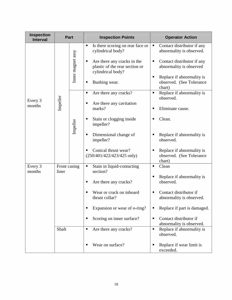
Inspection
Interval Part Inspection Points Operator Action
Inne
r mag
net a
ssy
��Is there scoring on rear face or cylindrical body?
��Are there any cracks in the
plastic of the rear section or cylindrical body?
��Bushing wear.
��Contact distributor if any abnormality is observed.
��Contact distributor if any
abnormality is observed ��Replace if abnormality is
observed. (See Tolerance chart)
Every 3 months
Impe
ller
Impe
ller
��Are there any cracks? ��Are there any cavitation
marks? ��Stain or clogging inside
impeller? ��Dimensional change of
impeller? ��Conical thrust wear? (250/401/422/423/425 only)
��Replace if abnormality is observed.
��Eliminate cause. ��Clean. ��Replace if abnormality is
observed. ��Replace if abnormality is
observed. (See Tolerance chart)
Front casing liner
��Stain in liquid-contacting section?
��Are there any cracks? ��Wear or crack on inboard
thrust collar? ��Expansion or wear of o-ring? ��Scoring on inner surface?
��Clean ��Replace if abnormality is
observed. ��Contact distributor if
abnormality is observed. ��Replace if part is damaged. ��Contact distributor if
abnormality is observed.
Every 3 months
Shaft ��Are there any cracks? ��Wear on surface?
��Replace if abnormality is observed.
��Replace if wear limit is
exceeded.
19
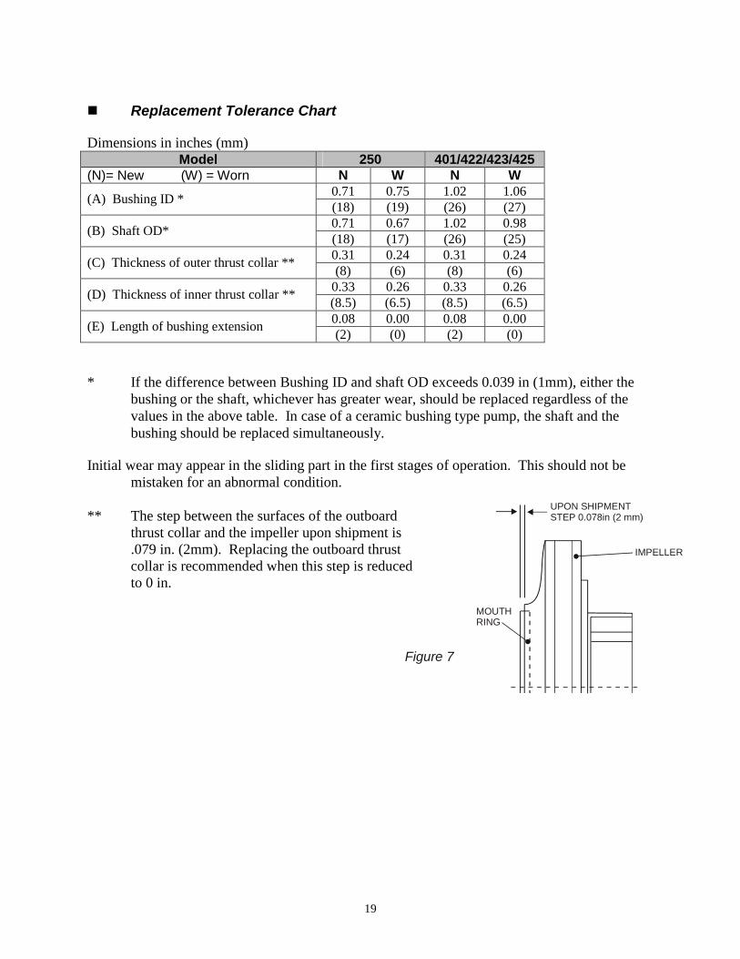
�� Replacement Tolerance Chart Dimensions in inches (mm)
Model 250 401/422/423/425 (N)= New (W) = Worn N W N W
0.71 0.75 1.02 1.06 (A) Bushing ID * (18) (19) (26) (27) 0.71 0.67 1.02 0.98 (B) Shaft OD* (18) (17) (26) (25) 0.31 0.24 0.31 0.24 (C) Thickness of outer thrust collar ** (8) (6) (8) (6) 0.33 0.26 0.33 0.26 (D) Thickness of inner thrust collar ** (8.5) (6.5) (8.5) (6.5) 0.08 0.00 0.08 0.00 (E) Length of bushing extension (2) (0) (2) (0)
* If the difference between Bushing ID and shaft OD exceeds 0.039 in (1mm), either the
bushing or the shaft, whichever has greater wear, should be replaced regardless of the values in the above table. In case of a ceramic bushing type pump, the shaft and the bushing should be replaced simultaneously.
Initial wear may appear in the sliding part in the first stages of operation. This should not be
mistaken for an abnormal condition. ** The step between the surfaces of the outboard
thrust collar and the impeller upon shipment is .079 in. (2mm). Replacing the outboard thrust collar is recommended when this step is reduced to 0 in.
Figure 7
UPON SHIPMENTSTEP 0.078in (2 mm)
IMPELLER
MOUTHRING
20
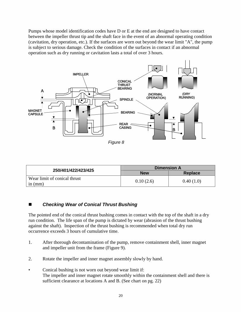
Pumps whose model identification codes have D or E at the end are designed to have contact between the impeller thrust tip and the shaft face in the event of an abnormal operating condition (cavitation, dry operation, etc.). If the surfaces are worn out beyond the wear limit "A", the pump is subject to serious damage. Check the condition of the surfaces in contact if an abnormal operation such as dry running or cavitation lasts a total of over 3 hours.
Dimension A 250/401/422/423/425 New Replace Wear limit of conical thrust in (mm) 0.10 (2.6) 0.40 (1.0)
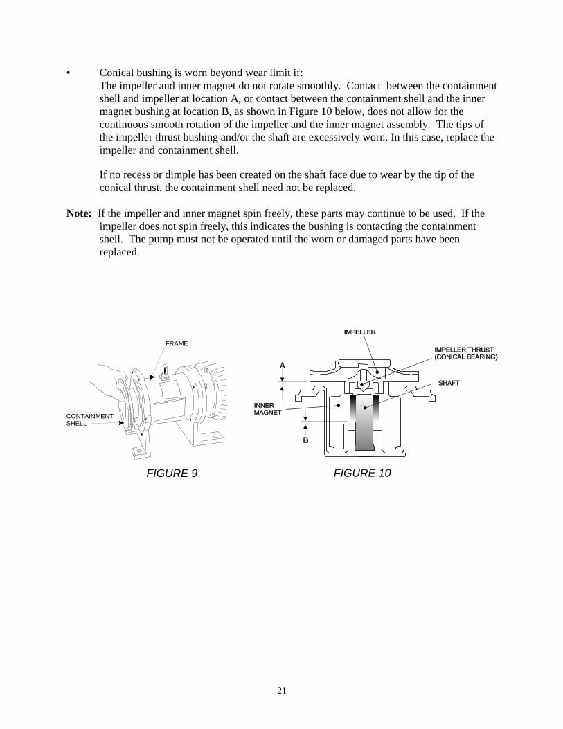
�� Checking Wear of Conical Thrust Bushing The pointed end of the conical thrust bushing comes in contact with the top of the shaft in a dry run condition. The life span of the pump is dictated by wear (abrasion of the thrust bushing against the shaft). Inspection of the thrust bushing is recommended when total dry run occurrence exceeds 3 hours of cumulative time. 1. After thorough decontamination of the pump, remove containment shell, inner magnet
and impeller unit from the frame (Figure 9). 2. Rotate the impeller and inner magnet assembly slowly by hand. • Conical bushing is not worn out beyond wear limit if:
The impeller and inner magnet rotate smoothly within the containment shell and there is sufficient clearance at locations A and B. (See chart on pg. 22)
Figure 8
21
• Conical bushing is worn beyond wear limit if: The impeller and inner magnet do not rotate smoothly. Contact between the containment shell and impeller at location A, or contact between the containment shell and the inner magnet bushing at location B, as shown in Figure 10 below, does not allow for the continuous smooth rotation of the impeller and the inner magnet assembly. The tips of the impeller thrust bushing and/or the shaft are excessively worn. In this case, replace the impeller and containment shell.
If no recess or dimple has been created on the shaft face due to wear by the tip of the conical thrust, the containment shell need not be replaced.
Note: If the impeller and inner magnet spin freely, these parts may continue to be used. If the
impeller does not spin freely, this indicates the bushing is contacting the containment shell. The pump must not be operated until the worn or damaged parts have been replaced.
FRAME
CONTAINMENT SHELL
FIGURE 9 FIGURE 10
22
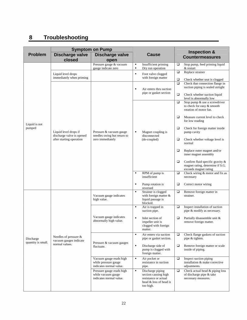
8 Troubleshooting
Symptom on Pump Problem Discharge valve
closed Discharge valve
open Cause Inspection &
Countermeasures
Pressure gauge & vacuum gauge indicate zero
�� Insufficient priming �� Dry run operation
�� Stop pump, feed priming liquid & restart
Liquid level drops immediately when priming �� Foot valve clogged
with foreign matter
�� Replace strainer �� Check whether seat is clogged
�� Air enters thru suction pipe or gasket section
�� Check that connection flange in suction piping is sealed airtight
�� Check whether suction liquid
level is abnormally low
�� Magnet coupling is disconnected
(de-coupled)
�� Stop pump & use a screwdriver to check for easy & smooth rotation of motor fan.
�� Measure current level to check
for low reading �� Check for foreign matter inside
pump cavity �� Check whether voltage level is
normal �� Replace outer magnet and/or
inner magnet assembly �� Confirm fluid specific gravity &
magnet rating, determine if S.G. exceeds magnet rating
Liquid is not pumped
Liquid level drops if discharge valve is opened after starting operation
Pressure & vacuum gauge needles swing but return to zero immediately
�� RPM of pump is insufficient
�� Pump rotation is
reversed
�� Check wiring & motor and fix as necessary
�� Correct motor wiring
Vacuum gauge indicates high value.
�� Strainer is clogged with foreign matter & liquid passage is blocked.
�� Remove foreign matter in strainer.
Vacuum gauge indicates abnormally high value.
�� Air is trapped in suction pipe.
�� Inlet section of
impeller unit is clogged with foreign matter.
�� Inspect installation of suction pipe & modify as necessary.
�� Partially disassemble unit &
remove foreign matter.
Pressure & vacuum gauges fluctuate.
�� Air enters via suction pipe or gasket section.
�� Discharge side of
pump is clogged with foreign matter.
�� Check flange gaskets of suction pipe & tighten.
�� Remove foreign matter or scale
inside of piping.
Vacuum gauge reads high while pressure gauge indicates normal value.
�� Air pocket or resistance in suction pipe.
�� Inspect suction piping installation & make corrective adjsutments.
Discharge quantity is small.
Needles of pressure & vacuum gauges indicate normal values.
Pressure gauge reads high while vacuum gauge indicates normal value.
�� Discharge piping section causing high resistance or actual head & loss of head is too high.
�� Check actual head & piping loss of discharge pipe & take necessary measures.
23
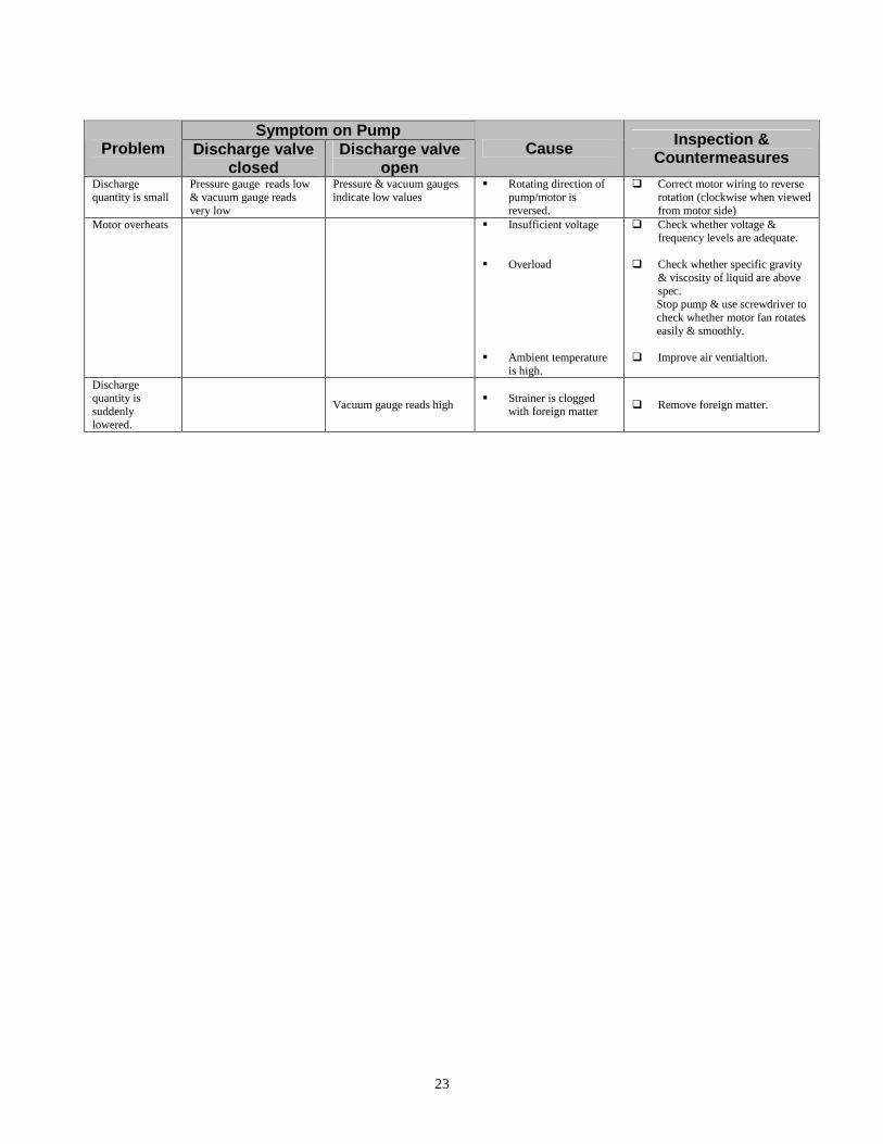
Symptom on Pump
Problem Discharge valve closed
Discharge valve open
Cause Inspection & Countermeasures
Discharge quantity is small
Pressure gauge reads low & vacuum gauge reads very low
Pressure & vacuum gauges indicate low values
�� Rotating direction of pump/motor is reversed.
�� Correct motor wiring to reverse rotation (clockwise when viewed from motor side)
Motor overheats �� Insufficient voltage �� Overload �� Ambient temperature
is high.
�� Check whether voltage & frequency levels are adequate.
�� Check whether specific gravity
& viscosity of liquid are above spec.
Stop pump & use screwdriver to check whether motor fan rotates easily & smoothly.
�� Improve air ventialtion.
Discharge quantity is suddenly lowered.
Vacuum gauge reads high �� Strainer is clogged with foreign matter �� Remove foreign matter.
24
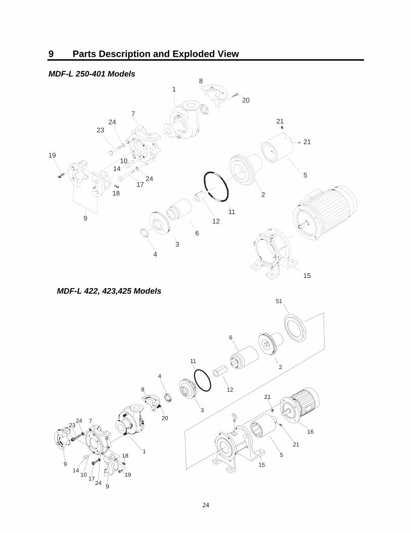
9 Parts Description and Exploded View MDF-L 250-401 Models
19
9
1817
2414
10
2324
7
18
20
2
1112
6
34
21
5
15
21
MDF-L 422, 423,425 Models
2324 7
118
19
9
9
2417
1014
203
8
4
11
21
21
16
5
15
2
6
12
51
25
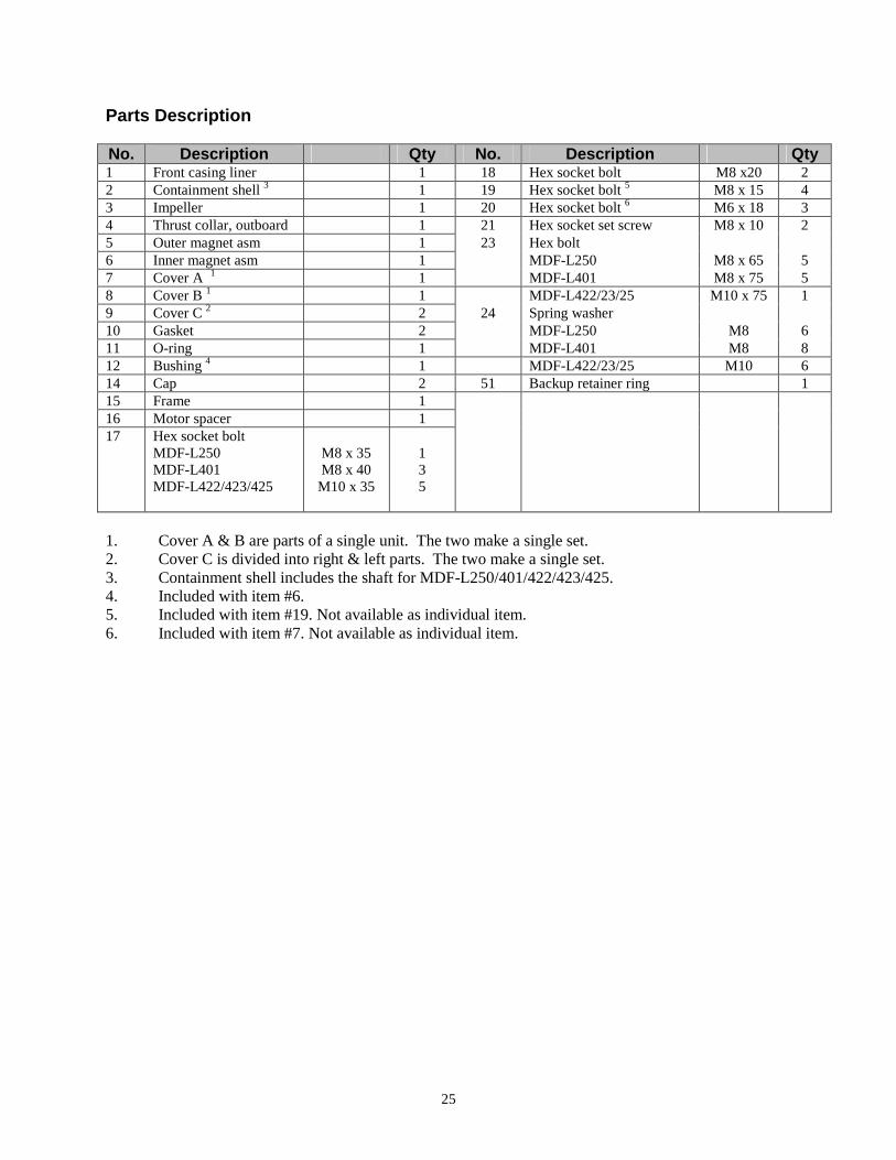
Parts Description No. Description Qty No. Description Qty 1 Front casing liner 1 18 Hex socket bolt M8 x20 2 2 Containment shell 3 1 19 Hex socket bolt 5 M8 x 15 4 3 Impeller 1 20 Hex socket bolt 6 M6 x 18 3 4 Thrust collar, outboard 1 21 Hex socket set screw M8 x 10 2 5 Outer magnet asm 1 23 Hex bolt 6 Inner magnet asm 1 MDF-L250 M8 x 65 5 7 Cover A 1 1 MDF-L401 M8 x 75 5 8 Cover B 1 1 MDF-L422/23/25 M10 x 75 1 9 Cover C 2 2 24 Spring washer 10 Gasket 2 MDF-L250 M8 6 11 O-ring 1 MDF-L401 M8 8 12 Bushing 4 1 MDF-L422/23/25 M10 6 14 Cap 2 51 Backup retainer ring 1 15 Frame 1 16 Motor spacer 1 17 Hex socket bolt
MDF-L250 MDF-L401 MDF-L422/423/425
M8 x 35 M8 x 40
M10 x 35
1 3 5
1. Cover A & B are parts of a single unit. The two make a single set. 2. Cover C is divided into right & left parts. The two make a single set. 3. Containment shell includes the shaft for MDF-L250/401/422/423/425. 4. Included with item #6. 5. Included with item #19. Not available as individual item. 6. Included with item #7. Not available as individual item.
26
10 Disassembly and Assembly of Pump
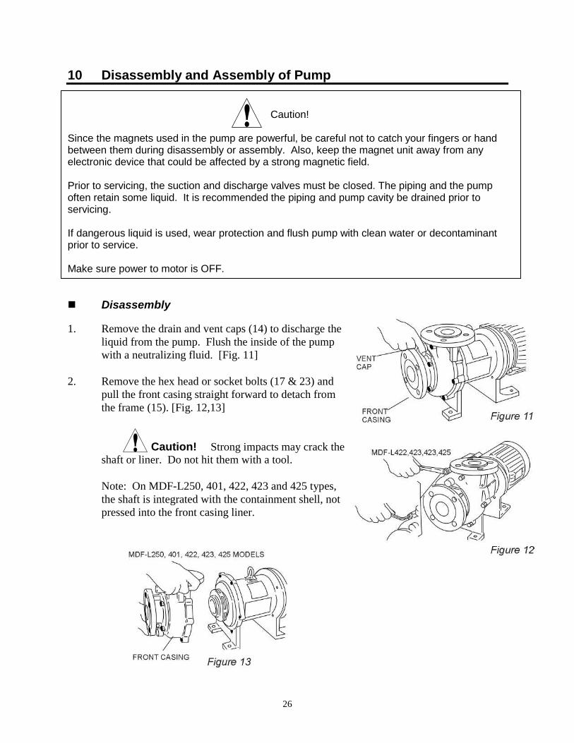
Caution! Since the magnets used in the pump are powerful, be careful not to catch your fingers or hand between them during disassembly or assembly. Also, keep the magnet unit away from any electronic device that could be affected by a strong magnetic field. Prior to servicing, the suction and discharge valves must be closed. The piping and the pump often retain some liquid. It is recommended the piping and pump cavity be drained prior to servicing. If dangerous liquid is used, wear protection and flush pump with clean water or decontaminant prior to service. Make sure power to motor is OFF. �� Disassembly 1. Remove the drain and vent caps (14) to discharge the
liquid from the pump. Flush the inside of the pump with a neutralizing fluid. [Fig. 11]
2. Remove the hex head or socket bolts (17 & 23) and
pull the front casing straight forward to detach from the frame (15). [Fig. 12,13]
Caution! Strong impacts may crack the shaft or liner. Do not hit them with a tool.
Note: On MDF-L250, 401, 422, 423 and 425 types, the shaft is integrated with the containment shell, not pressed into the front casing liner.
27
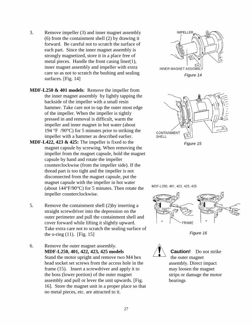
3. Remove impeller (3) and inner magnet assembly (6) from the containment shell (2) by drawing it forward. Be careful not to scratch the surface of each part. Since the inner magnet assembly is strongly magnetized, store it in a place free of metal pieces. Handle the front casing liner(1), inner magnet assembly and impeller with extra care so as not to scratch the bushing and sealing surfaces. [Fig. 14]
MDF-L250 & 401 models: Remove the impeller from
the inner magnet assembly by lightly tapping the backside of the impeller with a small resin hammer. Take care not to tap the outer most edge of the impeller. When the impeller is tightly pressed in and removal is difficult, warm the impeller and inner magnet in hot water (about 194 °F /90°C) for 5 minutes prior to striking the impeller with a hammer as described earlier.
MDF-L422, 423 & 425: The impeller is fixed to the magnet capsule by screwing. When removing the impeller from the magnet capsule, hold the magnet capsule by hand and rotate the impeller counterclockwise (from the impeller side). If the thread part is too tight and the impeller is not disconnected from the magnet capsule, put the magnet capsule with the impeller in hot water (about 144°F/90°C) for 5 minutes. Then rotate the impeller counterclockwise.
5. Remove the containment shell (2)by inserting a
straight screwdriver into the depression on the outer perimeter and pull the containment shell and cover forward while lifting it slightly upward. Take extra care not to scratch the sealing surface of the o-ring (11). [Fig. 15]
6. Remove the outer magnet assembly. MDF-L250, 401, 422, 423, 425 models Stand the motor upright and remove two M4 hex
head socket set screws from the access hole in the frame (15). Insert a screwdriver and apply it to the boss (lower portion) of the outer magnet assembly and pull or lever the unit upwards. [Fig. 16]. Store the magnet unit in a proper place so that no metal pieces, etc. are attracted to it.
Caution! Do not strike the outer magnet
assembly. Direct impact may loosen the magnet strips or damage the motor bearings
Figure 14
Figure 15
Figure 16
28
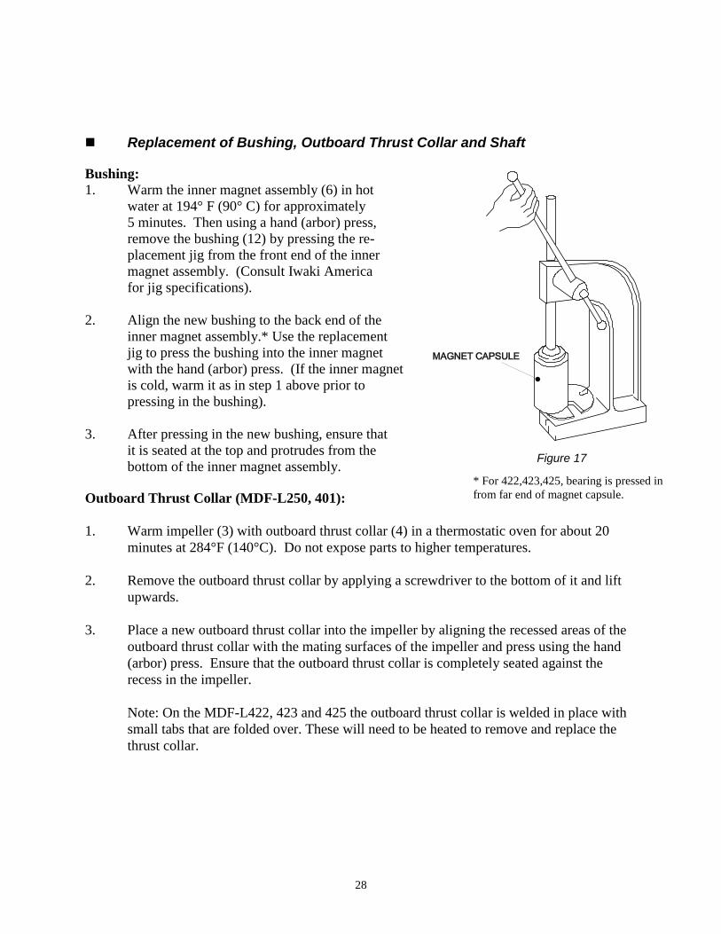
�� Replacement of Bushing, Outboard Thrust Collar and Shaft Bushing: 1. Warm the inner magnet assembly (6) in hot water at 194° F (90° C) for approximately
5 minutes. Then using a hand (arbor) press, remove the bushing (12) by pressing the re- placement jig from the front end of the inner magnet assembly. (Consult Iwaki America
for jig specifications). 2. Align the new bushing to the back end of the
inner magnet assembly.* Use the replacement jig to press the bushing into the inner magnet with the hand (arbor) press. (If the inner magnet is cold, warm it as in step 1 above prior to pressing in the bushing).
3. After pressing in the new bushing, ensure that
it is seated at the top and protrudes from the bottom of the inner magnet assembly.
Outboard Thrust Collar (MDF-L250, 401): 1. Warm impeller (3) with outboard thrust collar (4) in a thermostatic oven for about 20
minutes at 284°F (140°C). Do not expose parts to higher temperatures. 2. Remove the outboard thrust collar by applying a screwdriver to the bottom of it and lift
upwards. 3. Place a new outboard thrust collar into the impeller by aligning the recessed areas of the
outboard thrust collar with the mating surfaces of the impeller and press using the hand (arbor) press. Ensure that the outboard thrust collar is completely seated against the recess in the impeller.
Note: On the MDF-L422, 423 and 425 the outboard thrust collar is welded in place with small tabs that are folded over. These will need to be heated to remove and replace the thrust collar.
Figure 19* For 422,423,425, bearing is pressed in from far end of magnet capsule.
Figure 17
29
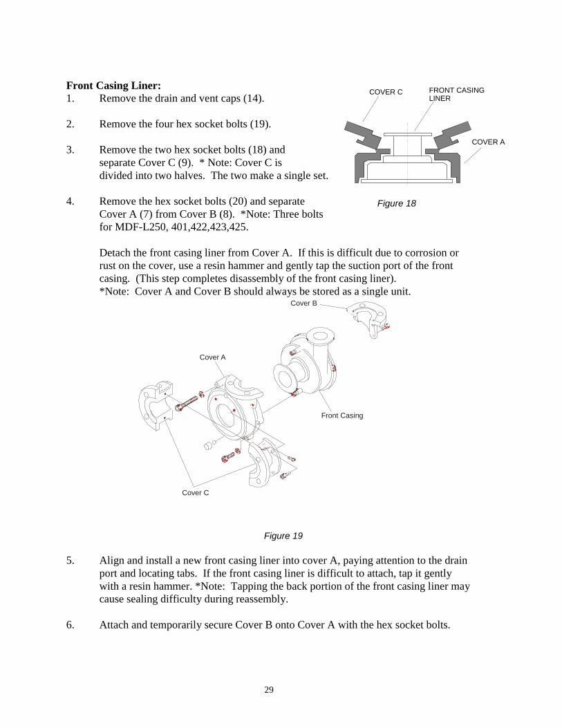
Front Casing Liner: 1. Remove the drain and vent caps (14). 2. Remove the four hex socket bolts (19). 3. Remove the two hex socket bolts (18) and separate Cover C (9). * Note: Cover C is
divided into two halves. The two make a single set. 4. Remove the hex socket bolts (20) and separate
Cover A (7) from Cover B (8). *Note: Three bolts for MDF-L250, 401,422,423,425.
Detach the front casing liner from Cover A. If this is difficult due to corrosion or rust on the cover, use a resin hammer and gently tap the suction port of the front casing. (This step completes disassembly of the front casing liner). *Note: Cover A and Cover B should always be stored as a single unit.
5. Align and install a new front casing liner into cover A, paying attention to the drain
port and locating tabs. If the front casing liner is difficult to attach, tap it gently with a resin hammer. *Note: Tapping the back portion of the front casing liner may cause sealing difficulty during reassembly.
6. Attach and temporarily secure Cover B onto Cover A with the hex socket bolts.
FRONT CASING LINER
COVER C
COVER A
Figure 20
Cover B
Front Casing
Cover A
Cover C
Figure 21
Figure 18
Figure 19
30
7. Attach and temporarily secure the two halves of Cover C (9) to Cover A (7) with the hex socket bolts (17). Tap the two parts gently in a slanted direction from the front casing liner suction port. [Fig. 19]
8. Align Covers A, B and C and secure all hex socket bolts tightly. 9. Insert gasket (10) into the vent and drain caps (14) prior to installing them. �� Reassembly Reassemble the pump by reversing the order of disassembly. Refer to the exploded view diagram on page 24 for parts and locations. Pay attention to the following points: • Replacement of o-ring and gasket When reassembling pump, always replace the o-ring and gaskets. In addition,
confirm that the o-ring and gaskets are not twisted or pinched by another part. The sealing section should be cleaned free of dust or scratches before installation.
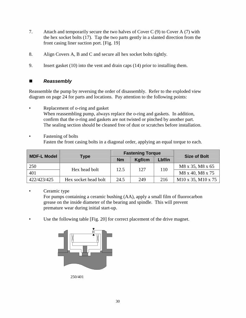
• Fastening of bolts Fasten the front casing bolts in a diagonal order, applying an equal torque to each.
Fastening Torque MDF-L Model Type
Nm Kgf/cm Lbf/in Size of Bolt
250 M8 x 35, M8 x 65 401
Hex head bolt 12.5 127 110 M8 x 40, M8 x 75
422/423/425 Hex socket head bolt 24.5 249 216 M10 x 35, M10 x 75 • Ceramic type For pumps containing a ceramic bushing (AA), apply a small film of fluorocarbon
grease on the inside diameter of the bearing and spindle. This will prevent premature wear during initial start-up.
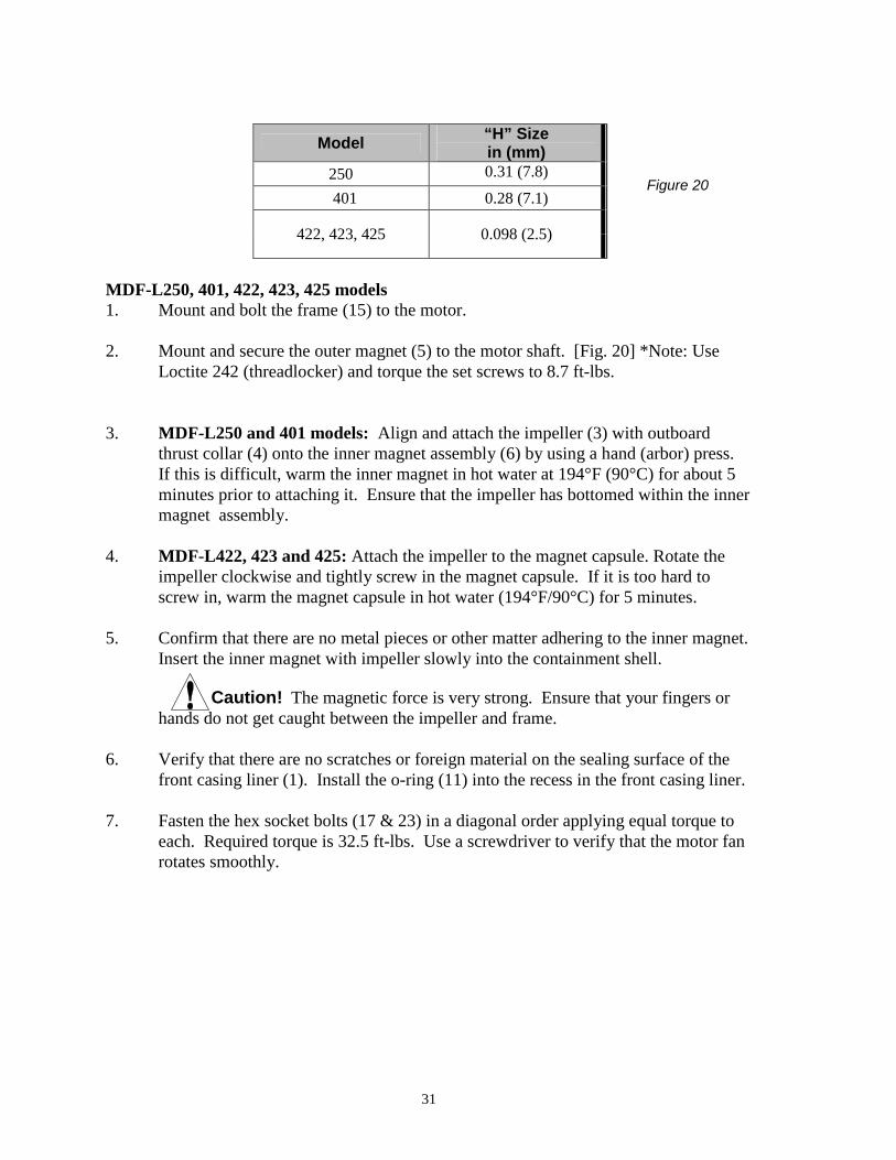
• Use the following table [Fig. 20] for correct placement of the drive magnet.
H
250/401
31
Model “H” Size in (mm)
250 0.31 (7.8)
401 0.28 (7.1)
422, 423, 425 0.098 (2.5)
MDF-L250, 401, 422, 423, 425 models 1. Mount and bolt the frame (15) to the motor. 2. Mount and secure the outer magnet (5) to the motor shaft. [Fig. 20] *Note: Use
Loctite 242 (threadlocker) and torque the set screws to 8.7 ft-lbs. 3. MDF-L250 and 401 models: Align and attach the impeller (3) with outboard
thrust collar (4) onto the inner magnet assembly (6) by using a hand (arbor) press. If this is difficult, warm the inner magnet in hot water at 194°F (90°C) for about 5 minutes prior to attaching it. Ensure that the impeller has bottomed within the inner magnet assembly.
4. MDF-L422, 423 and 425: Attach the impeller to the magnet capsule. Rotate the impeller clockwise and tightly screw in the magnet capsule. If it is too hard to screw in, warm the magnet capsule in hot water (194°F/90°C) for 5 minutes.
5. Confirm that there are no metal pieces or other matter adhering to the inner magnet.
Insert the inner magnet with impeller slowly into the containment shell. Caution! The magnetic force is very strong. Ensure that your fingers or
hands do not get caught between the impeller and frame. 6. Verify that there are no scratches or foreign material on the sealing surface of the
front casing liner (1). Install the o-ring (11) into the recess in the front casing liner. 7. Fasten the hex socket bolts (17 & 23) in a diagonal order applying equal torque to
each. Required torque is 32.5 ft-lbs. Use a screwdriver to verify that the motor fan rotates smoothly.
Figure 20
32
11 Spare Parts Appropriate spare parts are necessary to ensure continued pump operation. Expendable parts, such as bushings, shaft and outer thrust collar, should always be kept on hand. Consult your distributor or Iwaki America for the correct part number and pricing. When placing orders, supply the following information. 1. Description and item number (according to this instruction manual). 2. Pump model number and serial number (as shown on the nameplate of the pump). 3. Drawing number if you have received a certified drawing.
33
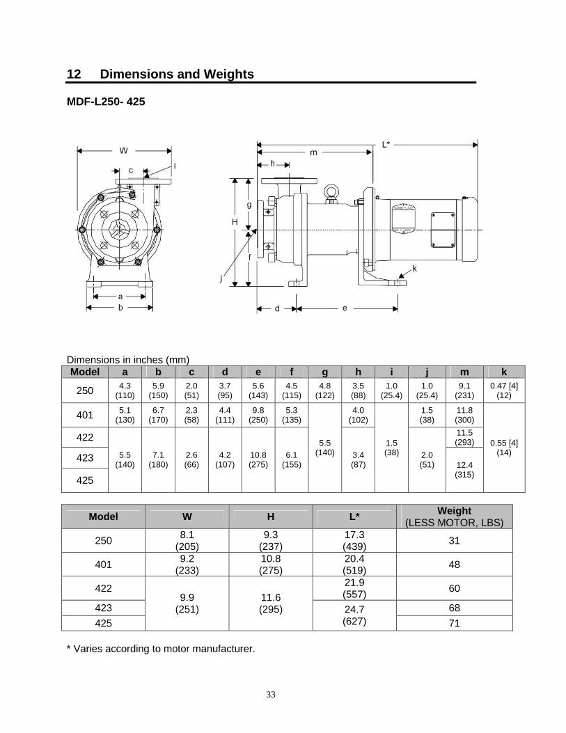
12 Dimensions and Weights MDF-L250- 425 Dimensions in inches (mm) Model a b c d e f g h i j m k
250 4.3 (110)
5.9 (150)
2.0 (51)
3.7 (95)
5.6 (143)
4.5 (115)
4.8 (122)
3.5 (88)
1.0 (25.4)
1.0 (25.4)
9.1 (231)
0.47 [4] (12)
401 5.1 (130)
6.7 (170)
2.3 (58)
4.4 (111)
9.8 (250)
5.3 (135)
4.0 (102)
1.5 (38)
11.8 (300)
422 11.5 (293)
423
425
5.5 (140)
7.1 (180)
2.6 (66)
4.2 (107)
10.8 (275)
6.1 (155)
5.5 (140) 3.4
(87)
1.5 (38) 2.0
(51) 12.4 (315)
0.55 [4] (14)
Model W H L* Weight (LESS MOTOR, LBS)
250 8.1 (205)
9.3 (237)
17.3 (439) 31
401 9.2 (233)
10.8 (275)
20.4 (519) 48
422 21.9 (557) 60
423 68 425
9.9 (251)
11.6 (295) 24.7
(627) 71 * Varies according to motor manufacturer.

Iwaki America Corporation 5 Boynton Road Hopping Brook Park Holliston MA 01746-1446 USA
TEL: 508-429-1440 FAX: 508-429-1386 Website: www.iwakiwalchem.com