Embed Size (px)
Citation preview
IVQ in TelecommunicationSystems 2730Technician Diploma
www.cityandguilds.com
Publications and enquiriesCity & Guilds publications are available from
Publications SalesCity & Guilds1 Giltspur StreetLondonEC1A 9DDUnited KingdomT +44 (0)20 7294 2850F +44 (0)20 7294 3387
General information about City & Guilds may be obtained from Customer Relations at the above address, or on 020 7294 3500, or by [email protected]
Equal opportunitiesCity & Guilds fully supports the principle of equal opportunities and we are committed to satisfying this principle in all our activities and published material.
Every effort has been made to ensure that the information contained in this publication is true and correct at the time of going to press. However, City & Guilds’ products and services are subject to continuous development and improvement and the right is reserved to change products and services from time to time. City & Guilds cannot accept liability for loss or damage arising from the use of information in this publication.
©2003 The City and Guilds of London Institute. All rights reserved.City & Guilds is a trademark of the City and Guilds of London Institute.
1 Giltspur StreetLondonEC1A 9DDT +44 (0)20 7294 2468F +44 (0)20 7294 2400www.cityandguilds.com
IVQ in TelecommunicationSystems 2730Technician Diploma
ST80252/06.03/I-00036391
Printed onrecycled paper
A C C R E D I T E D

[ This page is intentionally blank]
05 IVQ in Telecommunication Systems 2730
05 About City & Guilds
05 About e-skills UK
05 Introduction to this programme
05 Certificate
05 Diploma
05 Advanced Diploma
05 Full Technological Diploma
06 Making entries for assessments
06 Internal candidates
06 External candidates
06 Resources
06 Assessments
06 Award number
06 Component numbers
07 Technician Diploma in Applied Telecommunication Systems
07 Technician Diploma in Telecommunication Systems Theory
07 Fixed and free dates
08 Results and certification
08 How to offer this programme
08 Subject approval
08 Examination centre approval
08 Other information
08 Designing courses of study
09 Presentation format of units
09 Practical competences
09 Knowledge requirements
09 Practical assignments
10 Entry levels
10 Progression routes and recognition
10 Useful publications
11 SyllabusIVQ in Telecommunication Systems 2730
12 011 Fundamentals of Electronic Communication 201 Applied mathematics
13 011 Fundamentals of Electronic Communication 202 Boolean algebra, logic gates and relaxation oscillators
14 011 Fundamentals of Electronic Communication 203 Telecommunications systems and networks
16 011 Fundamentals of Electronic Communication 204 Noise
17 011 Fundamentals of Electronic Communication 205 Logarithms and decibels
18 011 Fundamentals of Electronic Communication 206 Transmission lines
19 011 Fundamentals of Electronic Communication 207 The basic principles of filters and radio frequency (r.f.) oscillators
20 011 Fundamentals of Electronic Communication 208 Modulation
22 Assessment
23 012 Communication Systems and Digital Networks 201 Data communication fundamentals
24 012 Communication Systems and Digital Networks 202 The Open Systems Interconnection (OSI) reference model
25 012 Communication Systems and Digital Networks 203 Transmission Control Protocol / Internet Protocol (TCP/IP)
27 012 Communication Systems and Digital Networks 204 Data packets, frames and cells
29 012 Communication Systems and Digital Networks 205 Switching and routing
31 Assessment
32 013 Fundamentals of Electronic Communication 301 Stabilised power supplies
33 013 Fundamentals of Electronic Communication 302 Optical fibre systems
34 013 Fundamentals of Electronic Communication 303 Modulation
35 013 Fundamentals of Electronic Communication 304 Digital transmission and multiplexing
36 013 Fundamentals of Electronic Communication 305 Pulse modulation and Time Division Multiplex (TDM) systems
38 013 Fundamentals of Electronic Communication 306 Access network and digital telephone exchanges
40 Assessment
41 014 Communication Systems and Digital Networks 301 Structured cabling
42 014 Communication Systems and Digital Networks 302 Local Area Networks (LANs), Metropolitan Area Networks(MANs) and Wide Area Networks (WANs)
43 014 Communication Systems and Digital Networks 303 Transmission systems
44 014 Communication Systems and Digital Networks 304 End systems
45 014 Communication Systems and Digital Networks 305 Network management
47 014 Communication Systems and Digital Networks 306 Internet Data Centre (IDC)
48 Assessment
49 015 Telecommunication Systems Practice 2/3
50 Practical assignments – Fundamentals of ElectronicCommunication 2
53 Practical assignments – Fundamentals of ElectronicCommunication 2
55 Practical assignments – Communication Systems and Digital Networks 2
Contents
IVQ in Telecommunication Systems 273004
57 Practical assignments – Communication Systems and Digital Networks 2
59 Practical assignments – Communication Systems and Digital Networks 2
62 Practical assignments – Fundamentals of ElectronicCommunication 3
64 Practical assignments – Fundamentals of ElectronicCommunication 3
68 Practical assignments – Communication Systems and Digital Networks 3
70 Practical assignments – Communication Systems and Digital Networks 3
72 Practical assignment – Communication Systems and Digital Networks 3
74 Practical assignments – Communication Systems and Digital Networks 3
76 Practical assignments – Communication Systems and Digital Networks 3
78 016 Radio systems
84 Assessment
85 Practical assignments – Radio Systems Practice
88 018 Programming Principles
90 Assessment
91 Practical assignments – Programming Principals Practice
93 020 Advanced Mathematics 1
96 Assessment
97 Appendix AAcronyms and abbreviations
101 Appendix BResource requirements
102 Diploma – resource list
103 Appendix CPractical assignments
103 Practical assignments
103 Instructor notes
103 Candidate instructions
103 Marking
103 Supervision
103 Records, results and certification
103 Visiting verifier
105 Appendix DThe levels of our awards
105 Progressive structure
About City & Guilds
We provide assessment and certification services for schools andcolleges, business and industry, trade associations andgovernment agencies in more than 100 countries. We have over120 years of experience in identifying training needs, developingassessment materials, carrying out assessments and trainingassessment staff. We award certificates to people who haveshown they have mastered skills that are based on world-classstandards set by industry. City & Guilds International provides aparticular service to customers around the world who need high-quality assessments and certification.
About e-skills UK
e-skills UK is the industry representative body responsible foraddressing the needs of IT and telecommunications employers inthe UK for a world class workforce in the information age.
e-skills UK benchmarked the City & Guilds award inTelecommunication Systems against the occupational standardsfor the UK telecommunications industry.
In meeting these requirements we at City & Guilds also raised thestandard of training design and delivery, an achievementreflected in our accreditation by e-skills UK.
Successful candidates benefit from this accreditation when theyapply for jobs in the UK.
Introduction to this programme
We have designed the Technician Awards in TelecommunicationSystems for those undergoing training or employed in this area ofwork. The programme aims to reflect the international nature ofthe knowledge and skills and activities needed for differentcountries or cultures.
We do not say the amount of time a candidate would need tocarry out the programme, but we do provide advice on guidedlearning hours for each unit at each level. The programme hasthree levels.
CertificateThe certificate is an entry-level qualification that has beendesigned for young people who have just left school, or for anyoneseeking a career change. Graduates of the programme should beable to obtain employment within the telecommunicationsindustry at the technician level in the fields of manufacture,installation, maintenance or operation. The certificate will alsoprovide useful underpinning knowledge for those alreadyemployed in the industry at the technician or craft level.
The certificate has been designed for a minimum of 300 guidedlearning hours. Candidates will be expected to study for anequivalent period of their own time, in order to achieve success.
DiplomaThe diploma (about 600 guided learning hours) provides morepractice involving a broader range of skills appropriate to aperson who may also supervise, or who wishes to progress intohigher education. Graduates of the diploma should have a well-developed knowledge of the technical and design principles ofcomplex telecommunication systems enabling them to fulfil therole of technician/senior technician across a range of specialiseddisciplines.
Advanced DiplomaThe advanced diploma (600 guided learning hours) takes theseskills to the level appropriate to a person preparing for, or workingin, first-level management. It is also appropriate for someone whowishes to receive specialised training at a high level. Graduates ofthe advanced diploma should have a sound knowledge of thetechnical design principles in one or more specialised branches oftelecommunications. They will have the potential to fulfil the roleof senior/chief technician with a high level of responsibilityrequiring the use of personal initiative and critical judgement.
We stress that these figures for guided learning hours are only aguideline. We award certificates for gaining and showing skills bywhatever mode of study, and not for periods of time spent in study.
We provide certificates for all work-related areas at seven levelswithin our structure of awards shown in appendix D. Thisprogramme covers level 3. The standards and assessments forthe certificate (level 2) and the advanced diploma (level 4) arepublished separately.
Full Technological DiplomaWe will award the Full Technological Diploma (FTD) inTelecommunication Systems to someone who is at least 21, whohas had at least two years of related work experience, and whohas successfully completed the assessments for the diploma andthe advanced diploma levels of this award. If candidates enter forthis diploma, they must also send us a portfolio of evidence tosupport their application.
IVQ in Telecommunication Systems 2730
Regulations: 2003 edition 05
Making entries for assessments
Candidates can only be entered for the assessments in thissubject if the approved examination centres agree. Candidatesmust enter through an examination centre we have approved tocarry out the assessments for 2730 Technician Awards inTelecommunication Systems.
There are two ways of entering candidates for assessments.
Internal candidatesCandidates can enter for examinations if they are taking or havealready finished a course at a school, college or similar traininginstitution that has directed their preparation whether by going toa training centre, working with another institution, or by openlearning methods.
External candidatesThese are candidates who have not finished a programme asdescribed above. The examination centres must receive theirapplication for entry well before the date of the examinationconcerned. This allows them to act on any advice you give aboutassessment arrangements or any further preparation needed.External candidates must carry out practical assignments andprojects if necessary, and they will need extra time and guidanceto make sure that they meet all the requirements for this part ofthe assessment.
In this publication we use the term ‘centre’ to mean a school,college, place of work or other institution.
Resources
If you want to use this programme as the basis for a course, youmust read this syllabus and make sure that you have the staff andequipment to carry out all parts of the programme. (See appendixB.) If there are no facilities for realistic practical work, we stronglyrecommend that you develop links with local industry to provideopportunities for hands-on experience.
Assessments
There is one level of Technician Diploma Award inTelecommunication Systems.
Certificate
We use a numbering system to allow entries to be made for ourawards. The numbers used for this programme are as follows.
Award number2730-02 Technician Diploma in Applied
Telecommunication Systems
Technician Diploma inTelecommunication Systems Theory
We use award numbers to describe the subject and level of the award.
Component numbers011 Fundamentals of Electronic Communication 2012 Communication Systems and
Digital Networks 2013 Fundamentals of Electronic
Communications 3014 Communication Systems and Digital Networks 3015 Telecommunication Systems Practice 2 / 3016 Radio Systems017 Radio Systems Practice018 Programming Principles019 Programming Principles Practice020 Advanced Mathematics 1
This unit is an option recommended for candidates enteringHigher Education.
We use component numbers to show units for which we mayaward a certificate of unit credit.
We use these numbers throughout this syllabus. You must usethese numbers correctly if you send forms to us.
IVQ in Telecommunication Systems 273006
Technician Diploma in Applied Telecommunication SystemsTo carry out what is needed for the Technician Diploma in AppliedTelecommunication Systems, candidates must be successful in allthe following assessments.
2730-02-011 Fundamentals of Electronic Communication 2(written paper which lasts three hours)
2730-02-012 Communication Systems and Digital Networks 2(written paper which lasts three hours)
2730-02-013 Fundamentals of Electronic Communication 3(written paper which lasts three hours)
2730-02-014 Communication Systems and Digital Networks 3(written paper which lasts three hours)
[2730-02-015] Telecommunication Systems Practice 2 / 3
Candidates must also be successful in one pair of the followingassessments:
either
2730-02-016 Radio Systems (written paper which lasts three hours)
[2730-02-017] Radio Systems Practice
or
2730-02-018 Programming Principles(written paper which lasts three hours)
[2730-02-019] Programming Principles Practice(Total five written papers)
The practical assignments are carried out during the learningprogramme and should be finished by the date of the writtenexamination so you can send all the results to us.(See appendix C.)
To receive this award candidates must carry out the followingpractical assignments:
• nine of 015/1, 015/2, 015/3, 015/4, 015/5, 015/6, 015/7, 015/8,015/9, 015/10, 015/11, 015/12
• and either 017/1• or 019/1.
(Total 10 practical assignments)
Technician Diploma in Telecommunication Systems TheoryTo carry out what is needed for the Technician Diploma inTelecommunication Systems Theory, candidates must besuccessful in all the following assessments.
2730-02-011 Fundamentals of Electronic Communication 2(written paper which lasts three hours)
2730-02-012 Communication Systems and Digital Networks 2(written paper which lasts three hours)
2730-02-013 Fundamentals of Electronic Communication 3(written paper which lasts three hours)
2730-02-014 Communication Systems and Digital Networks 3(written paper which lasts three hours)
Candidates must also be successful in one of the following units:
2730-02-016 Radio Systems(written paper which lasts three hours)
2730-02-018 Programming Principles(written paper which lasts three hours)
(Total five written papers)
There are no practical assignments for this award.
We provide assessments in two ways.
a Fixed dateThese are assessments that are carried out on dates and times we set. These assessments have no brackets around their numbers.
b Free dateThese are assessments that are carried out at a college or other training establishment on a date or over a period that the college chooses. These assessments have brackets around their numbers.
In this programme the written assessments are fixed date. Thepractical assignments are free date.
You must carry out assessments according to our InternationalDirectory of Examinations and Assessments. If there are anydifferences between information in this publication and the currentdirectory, the directory has the most up-to-date information.
Syllabus: 2003 edition 07
Results and certification
Everyone who enters for our certificates, diplomas, and advanceddiplomas receives a ‘Notification of Candidate Results’ givingdetails of how they performed.
If candidates successfully finish any assessment within thisprogramme (for example, any one of the examination papers)they will receive a certificate of unit credit towards the certificateor diploma for which they are aiming. We grade course workassessments as pass or fail. We grade written assessments on thebasis of fail, pass, credit or distinction. The certificate of unitcredit will not mention assessments that they do not enter, whichthey failed or from which they were absent.
Each certificate or diploma clearly states what candidates need for full certification at the relevant level, allowing schools,colleges and employers to see whether they have met the full requirements.
If candidates successfully finish all the requirements for a fullcertificate or a diploma, they will automatically receive theappropriate certificate.
We will send the ‘Notification of Candidate Results’, certificates ofunit credit, certificates, diplomas and advanced diplomas to theexamination centre to be awarded to successful candidates. It isyour responsibility to give the candidates the certificates. Ifcandidates have a question about the results and certificates,they must contact you. You may then contact us if necessary.
We will also send you a results list showing how all candidates performed.
How to offer this programme
To offer this programme you must get approval from us. There aretwo categories of approval.
Subject approvalWe give approval to offer a teaching course based on this syllabus.
Examination centre approvalWe give approval to enter candidates for examinations.
To be approved by us to offer a teaching course you must send usthe application form.
To enter candidates for examinations you must be approved by usas an examination centre. For this programme it is possible to actas a registered examination centre only, and accept externalcandidates. Approved examination centres must provide suitablefacilities for taking examinations, secure places to keep theexamination papers and materials, and may have an appointedvisiting verifier to review practical work.
After we have received and accepted an application, we will sendan approval letter confirming this. You can then send entries in atany time using the International Directory of Examinations andAssessments for guidance.
City & Guilds reserves the right to suspend an approved centre, orwithdraw its approval from an approved centre or for an approvedcentre to conduct a particular City & Guilds scheme or particularCity & Guilds schemes, for reason of debt, malpractice or for anyreason that may be detrimental to the maintenance of authentic,reliable and valid qualifications or that may prejudice the name ofCity & Guilds.
Please note that in this section we have provided anoverview of centre approval procedures. Please refer to the current issue of ‘Delivering InternationalQualifications – Centre Guide’ for full details of each aspect of these procedures.
Other informationDesigning courses of studyCandidates for the various Technician Awards inTelecommunication Systems will have come from differentbackgrounds and will have different employment and trainingexperiences. We recommend the following:
• carry out an assessment of the achievements so you can seewhat learning they already have and decide the level of entrythey will need; and
• consider what learning methods and places will best suit them.
When you assess a candidate’s needs, you should designteaching programmes that consider:
• what, if any, previous education qualifications or training thecandidate has, especially in the various general vocationaleducation certificates we provide; and
• what, if any, previous practical experience the candidate haswhich is relevant to the aims of the programme and from whichthey may have learned the relevant skills and knowledge.
When you choose learning methods and places, you shouldconsider the results of your assessments and whether thefollowing are available.
• Open or distance learning material.• Workplace learning that can be carried out on site or between
you and a local workplace. This will allow the candidates accessto specialised equipment and work experience.
• Working with other registered centres to share facilities.• Opportunities for co-operative learning between candidates for
different certificates who need to gain similar skills.
As long as the candidates meet the aims of this learningprogramme the structures of courses of study are up to you. So, itis possible to include extra topics that meet local needs.
IVQ in Telecommunication Systems 273008
However, we strongly advise you to offer the followingcomponents during the first year of the diploma course, and wealso strongly advise that you to test candidates on thosecomponents at the end of that year:
2730-02-011 Fundamentals of Electronic Communication 2
2730-02-012 Communication Systems and Digital Networks 2
We recommend the following components are offered during,and tested at the end of, the second year of the Diploma course:
2730-02-013 Fundamentals of Electronic Communication 3
2730-02-014 Communication Systems and Digital Networks 3
Again, we recommend that candidates should start with theirchosen optional component in year one, completing it at the endof year two of the Diploma.
Candidates who have chosen Advanced Mathematics 1 shouldstart with this component in year one, after having finished theApplied Mathematics unit in component 011. The test should takeplace at the end of year one, to give candidates the chance torepeat this component in the second year.
You should avoid teaching theory alone. As far as possible thepractical work should be closely related to work in the classroom(integrative approach) so that candidates use their theory in arealistic work environment. We recommend that you start withpractical assignments at an early stage in year one of the Diploma.
You can use formal lectures in the classroom with appropriateexercises and demonstrations. Candidates should keep recordsof the practical work they do so they can refer to it at a later date.
We assume that you will include key skills, such as numeracy,communication, working with people, and organisation andplanning throughout a teaching programme.
Presentation format of unitsPractical competencesEach unit starts with a section on practical competences whichshows the practical skills candidates must have.
At times we give more detail about important words in each‘competence statement’.
For example
3.14 Describe various methods of communicating over a channel.Methods: simplex (one-way communication), duplex (two-way communication), half/semi-duplex (two-waycommunication but only one-way at any one time),broadcast, serial, parallel
In the above statement the word ‘methods’ is given as a rangewhich the candidate should be familiar with. Candidates shouldcover the complete range. When a range starts with theabbreviation ‘eg’ the candidates only need to cover some of theranged areas or you can use suitable alternatives.
Knowledge requirementsImmediately after the section on practical competences the unittells you what knowledge is needed for that area. The knowledgeneeded is closely linked to the practical competences, so it is bestto teach the two together so that the candidate appreciates thetopic more.
Practical assignmentsYou should make sure all practical assignments are supervisedand instructors should make sure that the results reflect thecandidate’s own work. You must hold all the documents andmaterial in a file (portfolio) for each candidate for eight weeksafter the application for a certificate.
Syllabus: 2003 edition 09
Entry levels
We consider the following programmes to be relevant preparationfor this programme.
Technician Certificate in Telecommunication Systems (2730)Background to Technology (3660)
We also consider the following Pitman Qualifications award asrelevant alongside this programme.
English for Speakers of Other Languages – higher intermediate level
We also consider the following joint City &Guilds and NEBSManagement award as relevant alongside this programme.
International Management Award – Principles of Management
If candidates do not have the above qualifications, they shouldhave secondary school leaving passes in English andmathematics and science.
Progression routes and recognition
We consider the following programmes to be relevantprogression routes from this programme.
Advanced Diploma Awards in Engineering (2565)Advanced Diploma Awards in Telecommunication Systems (2730)Advanced Diploma Awards in Electrical and ElectronicEngineering (8030)
A number of universities and other higher education institutionsmay accept success at diploma and certificate (with appropriateexperience) level for direct entry onto bachelor degreeprogrammes. They may also accept success at the advanceddiploma level for advanced entry into the second year of theseprogrammes. The decision to accept a candidate onto a degreeprogramme, and the level of entry is at the discretion of theindividual institution.
Useful publications
We have listed relevant text books covering specific areas of thisprogramme in each section and also can provide a list ofsuggested text books. We may also have knowledge about othersupport materials. You should make sure that you have the latestinformation. We will automatically send updated lists to centreswe have approved to offer this programme.
We offer the following publications as additional supportmaterials to help you plan the delivery of International Vocational Qualifications:
Guide to the assessment of practical skills in InternationalVocational Qualifications
Preparing projects & portfolios for International Vocational Qualifications
Quality Handbook for Visiting Verifiers & Quality Inspectors
IVQ in Telecommunication Systems 273010
Component and section numbers
Technician Diploma
011 Fundamentals of Electronic Communication 2
01 Applied mathematics
02 Boolean algebra, logic gates and relaxation oscillators
03 Telecommunication systems and networks
04 Noise
05 Logarithms and decibels
06 Transmission lines
07 The basic principles of filters and radio frequency (r.f.) oscillators
08 Modulation
012 Communication Systems and Digital Networks 2
01 Data communication fundamentals
02 The Open Systems Interconnection (OSI) reference model
03 Transmission Control Protocol / Internet Protocol (TCP/IP)
04 Data packets, frames and cells
05 Switching and routing
013 Fundamentals of Electronic Communication 3
01 Stabilised power supplies
02 Optical fibre systems
03 Modulation
04 Digital transmission and multiplexing
05 Pulse modulation and Time Division Multiplex (TDM) systems
06 Access networks and digital telephone exchanges
014 Communication Systems and Digital Networks 3
1 Structured cabling
2 Local Area Networks (LANs), Metropolitan Area Networks(MANs) and Wide Area Networks (WANs)
3 Transmission systems
4 End systems
5 Network management
6 Internet Data Centre (IDC)
015 Telecommunication Systems Practice 2 / 3
016 Radio Systems
017 Radio Systems Practice
018 Programming Principles
019 Programming Principles Practice
020 Advanced Mathematics 1
SyllabusIVQ in Telecommunication Systems 2730
Syllabus: 2003 edition 11
Introduction
The aim of this section is to enable the candidate to
a acquire the fundamental mathematical knowledge forapplication to the diploma core components in the topicareas of communications and digital networks
b provide the foundation for the possible study of additionalmathematics as a diploma option (Advanced Mathematics 1).
Notes:
1 The subjects in this section would benefit if an integrativeapproach is used.
2 It is suggested that about 15 guided learning hours should begiven to this section.
Book list
Computer Studies (5th edition); C. S. French.Statistics (6th edition); W. M. Harper.Foundation Discrete Mathematics for Computing; D. J. Booth,Thomson.Foundation Mathematics (2nd edition); A.Croft & R. Davison,Addison-Wesley.
Practical competences
The demonstration of practical competences is not required forthis section.
Knowledge requirements
The instructor must ensure the candidate is able to:
Number systems1.1 Convert a compound denary number with fractions limited
to 1/32s to its binary equivalent and vice versa.
1.2 Use a sign bit to denote a negative quantity.
1.3 Define the modulus, 1s and 2s complement of a binary number, using numerical examples to illustrate the definitions.
1.4 Add two compound binary numbers.
1.5 Subtract one binary number from another usingcomplementary addition.
1.6 Multiply one binary number by another.
1.7 Divide one binary number by another.
1.8 Show, using numerical examples, that binary addition,subtraction, multiplication and division may beaccomplished using the add method.
1.9 Define the octal and hexadecimal number systems andconvert binary numbers to octal and hexadecimal forms.
1.10 Express octal and hexadecimal numbers in binary form.
1.11 Define the 8421 Binary Coded Decimal (BCD) system andderive the BCD equivalents of denary numbers.
1.12 Convert between denary numbers and their BCD equivalents.
1.13 Perform simple addition and subtraction using BCD andhexadecimal integer numbers.
Basic statistics1.14 Calculate the arithmetic mean for ungrouped data.
1.15 Arrange ungrouped data in rank order and determine themedian and modal values.
1.16 Calculate the arithmetic mean for grouped data.
1.17 Estimate the modal value of grouped data using a histogram.
1.18 Construct a cumulative frequency graph from a givenfrequency distribution.
1.19 Determine the median, quartiles, deciles and percentilesfrom cumulative frequency data.
1.20 Explain the circumstances most appropriate for the use ofeach of the three measures of location: arithmetic mean,median and mode.
1.21 Define the variance, and hence the standard deviation as ameasure of dispersion.
1.22 Calculate values of standard deviation for ungrouped dataand grouped data.
1.23 Calculate the range and semi-interquartile range as simplealterative measures of dispersion.
011 Fundamentals of Electronic Communication 201 Applied mathematics
IVQ in Telecommunication Systems 273012
Introduction
The aim of this section is to enable the candidate to
a understand the basics of combinational logicb apply the rules of Boolean algebra to logic gates.
Notes:
1 It is suggested that about 16 guided learning hours should begiven to this section.
Book list
Electronic Logic Circuits (3rd edition); J.R. Gibson andButterworth.Success in Electronics; Tom Duncan and John Murray.
Practical competences
The candidate must be able to do the following:
2.1 Use the laws of Boolean algebra and minimisationtechniques in order to develop a practical application of apre-determined task.
Knowledge requirements
The instructor must ensure the candidate is able to:
2.2 State that Boolean algebra is a mathematical treatment oflogical processes.
2.3 Define the basic Boolean operations of NOT, AND and OR.
2.4 Demonstrate, using simple examples, that all the possibleoutcomes of a logical process may be summarised using atruth table.
2.5 Demonstrate, using simple switch circuits, the followinglaws of Boolean algebra:A.B = B.A, A. 1 = A, A. 0 = 0, A . A = A, A. A– = 0 and A–
–= A
2.6 Demonstrate the following further laws of Boolean algebra:A + B = B + A, A + 1 = 1, A + 0 = A, A + A = A, A + A
–= 1,
A.B.C = A.(B.C) = (A.B).C,A + B + C = (A + B) + C = A + (B + C), A.(B + C) = A.B + A.C,A + B.C = (A + B).(A + C)
2.7 Sketch the British Standard and US military symbols forNOT, AND, OR, NAND and NOR elements.
2.8 Construct truth tables for the elements in 2.7.
2.9 Explain how the logic elements in 2.7 may be used toimplement Boolean expressions.
2.10 Describe a bistable as a two-state circuit that can act as a memory.
2.11 Explain how a bistable may be implemented with eitherNAND or NOR elements.
2.12 Construct the truth tables for the bistable elementsdescribed in 2.11.
2.13 Construct a truth table for a given logic function with up tothree input variables.
2.14 Use a truth table to derive a Boolean expression for theoutput function in terms of the input variables.
2.15 Determine the logic network to realise the Booleanexpressions derived in examples of 2.14.
2.16 Show how a Boolean expression may be represented by aKarnaugh map.
2.17 Derive the Boolean expression defined by a givenKarnaugh map with up to three input variables.
2.18 Minimise a logic function of up to three variables using:
i Boolean algebraii Karnaugh map grouping techniques.
2.19 State and prove, using truth tables, DeMorgan’s theorem.
2.20 Describe the implications of DeMorgan’s theorem in theimplementation of logic functions.
2.21 Explain the principles and applications of UnCommittedLogic Arrays (UCLAs) for the implementation of Boolean operations.
2.22 Derive NOT, AND and OR functions using only NAND orNOR logic elements.
2.23 Produce a given Boolean operation from a given set oflogic elements.
2.24 Distinguish between relaxation and sinewave oscillators.
2.25 Explain and compare the meanings of
i astableii monostableiii bistable.
2.26 Draw the symbols for the elements stated in 2.25 i), ii), iii).
2.27 Describe, using waveform diagrams, the operation of thecircuits drawn in 2.25 i), ii), iii).
2.28 Explain applications for the circuits in 2.25 i), ii), iii).
011 Fundamentals of Electronic Communication 202 Boolean algebra, logic gates and relaxation oscillators
Syllabus: 2003 edition 13
Introduction
The aim of this section is to enable the candidate to
a acquire the skills and understanding which relate to simple telecommunication networks and the range of signals carried.
Notes:
1 It is suggested that about 15 guided learning hours should begiven to this section.
Book list
Audio, Video and Data Telecommunications; David Peterson.
Practical competences
The demonstration of practical competences is not required forthis section.
Knowledge requirements
The instructor must ensure the candidate is able to:
3.1 Explain that telecommunication systems involve:
i the transfer of informationii the conditioning/coding of signals prior to transferiii the conditioning/decoding of signals after transfer.
3.2 Describe the need for direct current (d.c.) power supplieswhen using electronic devices.
3.3 Explain the terms:
i signal gainii signal lossiii signal distortion (shape).
3.4 Explain that the processes of
i amplification provides gainii attenuation provides loss.
3.5 Explain the difference between voltage gain, current gainand power gain.
3.6 Define the term frequency and explain that
i signals may be present or may be produced atdifferent frequencies
ii amplification can be provided at different frequenciesiii attenuation may exist or may be produced at different
frequencies.
3.7 Explain that amplifiers may be implemented by the use ofdiscrete components with Bipolar Junction Transistors(BJTs) or with Field Effect Transistors (FETs).
3.8 Explain that amplifiers may be implemented by the use ofintegrated circuit operational amplifiers (op-amps).
3.9 Describe the sources of conducted and radiatedinterference.Sources: electromagnetic radiation, unwanted signals
3.10 Describe sources of distortion.Sources: non-linearity, harmonics
3.11 Describe the properties of differing types of transmissionlinks (channels).Properties: typical attenuation in dB/km, susceptibility tointerference, unwanted radiation of signalsFixed links: wired (shielded and unshielded coppermultipairs, shielded and unshielded copper twisted pairs,copper coaxial), optical fibre, waveguide, point-to-pointwireless (line-of-sight), geostationary satelliteMobile links: wireless (radio), infrared, non-geostationary satellite
3.12 Explain the main features of signal waveforms.Features: amplitude, frequency, phase, wave shape, complex
3.13 Explain that complex waveforms can be considered asconsisting of a combination of sinusoidal waveforms.
3.14 Describe various methods of communicating over a channel.Methods: simplex (one-way communication), duplex(two-way communication), half/semi-duplex (two-waycommunication but only one-way at any one time),broadcast, serial, parallel
3.15 Describe the frequency ranges of speech, music and video waveforms.
3.16 Explain why the higher frequencies in the speech range arenot essential for effective communication.
3.17 Explain why, for good quality, music requires a greaterfrequency range than speech.
3.18 Explain why the greater the picture definition, the greaterthe video bandwidth required.
3.19 Explain the difference between baseband and broadband signals.
3.20 Describe the bandwidth of common analogue signals.Signals: commercial speech, hi-fi music, soundbroadcasting (l.f./m.f. and very high frequency (v.h.f.)),monochrome (black-and-white television), colour television
011 Fundamentals of Electronic Communication 203 Telecommunications systems and networks
IVQ in Telecommunication Systems 273014

3.21 Explain that a signal is attenuated due to losses in a cable.
3.22 Describe the need to amplify the signal at regular intervalsalong the line.
3.23 Describe the need for four-wire working.
3.24 Describe, with the aid of a diagram, the operation of a 2-4wire conversion unit.
3.25 Describe how a four-wire circuit could become unstable.
Syllabus: 2003 edition 15
Introduction
The aim of this section is to enable the candidate to understand
a the nature and sources of noiseb the effect of noise on telecommunications.
Notes:
1 It is suggested that about 14 guided learning hours should begiven to this section.
Book list
Modern Electronic Communication (7th Edition); Gary Miller.Electronic Communications Systems, William L. Schweber.
Practical competences
The demonstration of practical competences is not required forthis section.
Knowledge requirements
The instructor must ensure the candidate is able to:
4.1 Define noise in the context of communication systems.
4.2 Describe the effects of noise in communication systems.
4.3 Explain the sources of noise as man-made and natural.
4.4 Describe the sources of internal noise.Sources: thermal/Johnson, shot, flicker
4.5 Describe the sources of external noise.Sources: natural (eg sun, moon, sky, galactic, cosmic), artificial/man-made (eg ignition systems, rotating machinery)
4.6 List examples of the noise which may arise from thesources defined in 4.3 and 4.4.
4.7 Distinguish between ‘impulsive noise’ and ‘white noise’.
4.8 Define signal/noise ratio and express it in deciBels (dB).
4.9 Explain how the signal/noise ratio determines the accuracywith which received information can be identified.
4.10 Solve problems relating to signal/noise ratios.
4.11 Define noise Factor (F).
4.12 Define Noise Figure (NF).
4.13 Solve problems relating to F and NF.
4.14 Define thermal (Johnson) noise.
4.15 Explain that the thermal noise producing voltage (vn) for aresistance is given by the formula:vn = √–
(4kTBR) volts
4.16 Solve simple problems using the equation in 4.15.
4.17 Define noise temperature (Tn).
011 Fundamentals of Electronic Communication 204 Noise
IVQ in Telecommunication Systems 273016
Introduction
The aim of this section is to enable the candidate to
a apply the laws of logarithms to linear equations in order tosimplify gain/attenuation calculations.
Notes:
1 It is suggested that about 15 guided learning hours should begiven to this section.
Book list
Electronic Communications Systems; William L. Schweber.
Practical competences
The candidate must be able to do the following:
5.1 Apply the laws of logarithms in order to express in aconvenient form the gain or attenuation oftelecommunications systems.Gain: current, voltage, power
Knowledge requirements
The instructor must ensure the candidate is able to:
Logarithms and indicial equations
5.2 Define a logarithm to any base.
5.3 Convert a simple indicial equation to a logarithmicrelationship and vice versa.
5.4 Deduce the laws of logarithms for any base b in thefollowing forms:logb (xy) = logb x + logb y; logb (x / y) = logb x ( logb y; logb (xa) = a logb x
5.5 State that logb 1 = 0 and logb b = 1.
5.6 State that as x 0, logb x – ∞
5.7 Apply the laws of logarithms to simplify expressions.
5.8 Apply the laws of logarithms to solve equations.
5.9 State the base e of natural logarithms is approximately 2.718.
5.10 Define natural (Napierian) logarithms (loge x or ln x).
5.11 Evaluate expressions and solve equations using natural logarithms.
5.12 Deduce the relationship between natural and commonlogarithms.
5.13 Change the base of numbers using the laws of powers, eg 16 = 42, 27 = 33
5.14 Change the base of numbers where the index is inalgebraic form, such as 8x = 23x
5.15 Solve indicial equations where the indices are linear in one unknown.
5.16 Solve indicial equations where the indices are quadratic in one unknown.
5.17 Derive, from ‘blackbox’ models, the power gain or loss(attenuation) of a network or system.
5.18 Determine the advantages of the use of logarithmic units when
i dealing with large ranges of numbersii calculating the power gain or loss of networks
connected in tandem.
5.19 Define the decibel (dB).
5.20 Define the dBm (dB relative to 1mW), and describe its usein system calculations.
5.21 Define:
i voltage gain and loss in dBii current gain and loss in dB.
5.22 Derive the condition for
i power gain in dBii voltage gain in dBiii current gain in dB of a network or system.
5.23 Define signal/noise ratio in decibels.
5.24 Calculate, in dBs and as a power ratio, the overall gainand/or attenuation of simple systems given thegain/attenuation of the individual stages.
011 Fundamentals of Electronic Communication 205 Logarithms and decibels
Syllabus: 2003 edition 17
Introduction
The aim of this section is to enable the candidate to
a understand the characteristics of transmission lines andcables used for telecommunication purposes.
Notes:
1 It is suggested that about 14 guided learning hours should begiven to this section.
Book list
Modern Electronic Communication (7th Edition); Gary Miller.
Practical competences
The demonstration of practical competences is not required forthis section.
Knowledge requirements
The instructor must ensure the candidate is able to:
6.1 Describe the effect of metallic cables on analogue anddigital signals.
6.2 Explain the four primary coefficients of a transmission lineand sketch an equivalent circuit for a section of line.Coefficients: R, G, L and C
6.3 Describe why, in unloaded cables, R and C are the mostsignificant primary coefficients and produce the effect of alow-pass filter.
6.4 Define the terms commonly used in relation to atransmission line.Terms: characteristic impedance (Zo), attenuationcoefficient (a), phase-change coefficient (b)
6.5 Sketch typical attenuation/frequency and delay/frequencyresponse curves for unloaded and loaded cable, andcoaxial cable.
6.6 Describe the shape of the response curves in 6.5 in termsof the primary coefficients of the cables used.
6.7 Define the terms used in relation to the distortion effects ofa rectangular pulse.Terms: rise-time, sag
6.8 Explain the relationship between the 3dB bandwidth of aRC low-pass filter to which a rectangular pulse is appliedand the rise-time of the output pulse.
6.9 Explain how the attenuation/frequency anddelay/frequency characteristics of a cable affect analoguebandwidth and digital bitrate.
6.10 Describe the propagation of an electromagnetic wavealong a twin transmission line.
6.11 Explain why negligible radiation occurs from twin orconcentric lines.
6.12 Explain that steady current conditions do not apply in thecase of lines energised at radio frequencies.
6.13 Sketch an equivalent loss-free line in terms of itsdistributed L and C parameters.
6.14 Explain that maximum power can be drawn from the line ifits terminating load has a particular value.
6.15 Explain that, unless maximum power is drawn from theline, reflection will occur.
6.16 Define the characteristic impedance Zo of a line as equal tothe value of the terminating load that causes no reflectionand hence absorbs maximum power.
6.17 State the value of Zo in terms of the distributed L and Cparameters of a loss-free line.
6.18 Explain that Zo is the ratio of root mean square (r.m.s.)voltage to r.m.s. current for a wave propagated on a linewhich is terminated in its characteristic impedance.
6.19 Describe in simple terms, by considering voltageconditions, how a short-circuited termination causes total reflection.
6.20 Describe in simple terms how an open-circuitedtermination causes total reflection.
6.21 Show diagrammatically how reflection produces astanding wave.
6.22 Describe the effects of reflected waves in pulse systems.
6.23 Distinguish between travelling and standing waves.
6.24 Describe how the conductor and spacing dimensions ofopen-wire lines and coaxial cables affect the value ofcharacteristic impedance.
6.25 State typical values of Zo for open-wire and coaxial cables.
011 Fundamentals of Electronic Communication 206 Transmission lines
IVQ in Telecommunication Systems 273018
Introduction
The aim of this section is to enable the candidate to
a determine the characteristics of inductance andcapacitance, and their application to basic filters andoscillator circuits.
Notes:
1 It is suggested that about 10 guided learning hours should begiven to this section.
Book list
Modern Electronic Communication (7th Edition); Gary Miller.
Practical competences
The demonstration of practical competences is not required forthis section.
Knowledge requirements
The instructor must ensure the candidate is able to:
7.1 Sketch frequency response characteristics for filternetworks and indicate the 3 dB frequency.Filters: low-pass, high-pass, band-pass, band-stop
7.2 Sketch waveforms to show the effects of passing a complex wave through low-pass and high-pass filter circuits.
7.3 Identify from the frequency plots types of filter and sketchtheir standard block symbols.Filters: low-pass, high-pass, band-pass, band-stop
7.4 Determine the ultimate rate of signal voltage attenuationfor a single-pole RC filter circuit (6dB/octave /20dB/decade).
7.5 Describe in simple terms that the instantaneous currents ina parallel LC circuit flow in opposite directions.
7.6 Explain that at one particular frequency the currents in a parallel LC circuit become equal and opposite andhence that a parallel LC circuit has a high impedance at resonance.
7.7 State expressions, and calculate typical values, for theresonant frequency and dynamic impedance of a parallelLC circuit.
7.8 Explain that an amplifier is an active device (black boxtreatment) by which a small input voltage variation can beused to control current from a battery.
7.9 Explain that the voltage gain depends upon the value of theload connected in the output circuit of the amplifier.
7.10 Explain that an amplifier using a parallel LC circuit as a loadwill have maximum voltage gain at the resonant frequency.
7.11 Describe how a fraction of the voltage across the load canbe used to provide the amplifier input signal.
7.12 Describe an r.f. oscillator as a self-driven amplifier with aparallel LC circuit as the load.
7.13 Describe the tuning of r.f. oscillators by the adjustment of L and C.
011 Fundamentals of Electronic Communication 207 The basic principles of filters and radio frequency (r.f.) oscillators
Syllabus: 2003 edition 19
Introduction
The aim of this section is to enable the candidate to
a explain the principles of communicating information byvarying the characteristics of a waveform
b investigate the characteristics of various waveforms and the manner in which they can be varied in order toconvey information
c describe the characteristics of modulated signals.
Notes:
1 The subjects in this section would benefit if an integrativeapproach is used.
2 It is suggested that about 16 guided learning hours should begiven to this section.
Book list
Modern Electronic Communication (7th Edition); Gary Miller.
Practical competences
The demonstration of practical competences is not required forthis section.
Knowledge requirements
The instructor must ensure the candidate is able to:
Basic principles8.1 Explain the need for modulation.
8.2 Describe modulation as the process of superimposinginformation on a carrier wave.
8.3 Explain that modulation is the process whereby someproperty of a carrier wave is varied by a baseband wave.
8.4 Identify, from given waveform diagrams, the modulated wave for:
i Amplitude Modulation (AM)ii Frequency Modulation (FM)
Amplitude modulation8.5 Sketch an AM waveform in which the modulating signal is a
sine wave.
8.6 Show diagrammatically how audio frequency informationmay be superimposed upon a radio frequency carrier waveby varying its amplitude.
8.7 Sketch typical waveforms of a radio frequency (r.f.) carrierwave (fc) amplitude-modulated by a sinusoidal tone (fm);hence describe modulation depth.
8.8 Describe how am of an r.f. carrier wave by a sinusoidal tone produces a complex wave having three frequency components:
i fcii fc – fmiii fc + fm
8.9 Show graphically that the modulated wave can beconstructed from waveforms of carrier (fc), and sidefrequencies (fc + and – fm).
8.10 Define modulation depth as applied to an AM waveform.
8.11 Explain why modulation exceeding 100% results indistortion which appears in the demodulated output.
8.12 Describe, with the aid of a frequency spectrum diagram,the components of a double-sideband AM signal.
8.13 Describe, with the aid of a frequency spectrum diagram,the components of a single-sideband AM signal.
8.14 Describe the advantages of single-sideband systems withspecific reference to power, bandwidth and noise.
8.15 Describe the bandwidth requirements of a modulated carrier.
8.16 Show, by means of waveforms, demodulation as theprocess of recovering the audio frequency (a.f.)information from the envelope of a modulated wave.
8.17 Explain why over-modulation results in distortion whichappears at the demodulated output.
Frequency Modulation (FM) and Phase Modulation (PM)8.18 Explain that FM is the variation of the frequency of a
carrier in accordance with the instantaneous value of abaseband signal.
8.19 Describe the terms used in FM.Terms: frequency deviation, maximum deviation, deviation ratio
8.20 Explain that PM is the variation of the phase of a carrier in accordance with the instantaneous value of a baseband signal.
8.21 Show diagrammatically how a.f. information can besuperimposed upon a radio frequency carrier wave bycausing its frequency to deviate.
8.22 Explain that the frequency deviation of the carrier wavedepends upon the amplitude of the modulating signal butthat the amplitude of the carrier wave is unchanged.
011 Fundamentals of Electronic Communication 208 Modulation
IVQ in Telecommunication Systems 273020

8.23 Explain why the bandwidth required for an FM service israther more than twice the maximum deviation.
8.24 Explain why FM radio services operate at very highfrequency (v.h.f.) and above.
8.25 Sketch and describe the frequency/amplitudecharacteristic of a discriminator suitable for demodulatingan FM signal.
Syllabus: 2003 edition 21
Test specification for written paperFundamtals of Electronic Communication 2(2730-02-011)
This is a written examination paper lasting three hours with tenquestions. Candidates must answer all questions.
The examination paper will cover the knowledge specifications:
Approximate %examination
Topic weighting
01 Applied mathematics 14
02 Boolean algebra, logic gates and relaxation oscillators 16
03 Telecommunication systems and networks 14
04 Noise 8
05 Logarithms and decibels 14
06 Transmission lines 12
07 The basic principles of filters and radio frequency (r.f.) oscillators 8
08 Modulation 14
Assessment
IVQ in Telecommunication Systems 273022
Introduction
The aim of this section is to enable the candidate to understand
a the general concept of data networksb fundamental data networking terminology.
Notes:
1 It is suggested that about 10 guided learning hours should begiven to this section.
Book list
Business Data Communications (4th edition); Jerry Fitzgerald.Business Data Communications (4th edition); Stallings, Van Styke.Business Data Communications and Networking (7th edition);Jerry FitzGerald, Alan Dennis.Data Communications for Engineers; Michael Duck, Richard Read.Data and Computer Communications (6th edtion); William Stallings.
Practical competences
The candidate must be able to do the following:
1.1 Draw a block diagram illustrating and identifying thecomponents necessary to establish two-waycommunication between two computers over a publictelephone network system.
1.2 Locate and activate terminal emulation software on acomputer and record the parameter settings in theconfiguration section of the software.Parameter: bits per second (bps), bits, parity, stop bit,flow control
Knowledge requirements
The instructor must ensure the candidate is able to:
1.3 Identify the components of a simple communication system.Components: source, transmitter, transmission system,receiver, destination
1.4 Describe the different media used in data communication.Media: copper cable, fibre optical cable, radio waves
1.5 Explain the difference between digital and analogue signals.
1.6 Explain the meaning of bits and bytes in the context of data communication.Bits: binary digitsBytes: binary word
1.7 Describe the data formats of digital transmission.Data formats: serial, parallel
1.8 Describe the two forms of serial transmission.Forms: synchronous, asynchronous
1.9 Explain what is meant by
i circuit switchingii message switchingiii packet switchingiv fast packet switching.
1.10 Compare and contrast the relative advantages anddisadvantages of each of the switching methods listed in 1.9.
1.11 Describe the difference between connectionless (egdatagram) and connection-oriented(eg virtual circuit) packet switched networks.
1.12 Compare and contrast the relative advantages of thepacket switching methods listed in 1.11.
1.13 Explain the meaning of the term ‘protocol’ in the context ofdata communication.
1.14 Describe what is meant by each of the following:
i source codingii channel codingiii line coding.
1.15 Give examples of each method of coding listed in 1.14
1.16 Describe in relation to data communications what is meant by
i dataii informationiii redundancy
1.17 Compare and contrast the two basic methods of error correction.Methods: Automatic Repeat Request (ARQ), Forward Error Control (FEC).
012 Communication Systems and Digital Networks 201 Data communication fundamentals
Syllabus: 2003 edition 23
Introduction
The aim of this section is to enable the candidate to understand
a the purpose of the OSIb the main functions of each layer of the OSIc how the OSI relates to data networksd how network devices and protocols map onto the OSI.
Notes:
1 It is suggested that about 25 guided learning hours should begiven to this section.
Book list
OSI Explained: End-To-End Computer Communication Standards;John Henshall and Sandy Shaw.OSI Reference Model for Telecommunications; Debbra Wetteroth.
Practical competences
The candidate must be able to do the following:
2.1 Set up two computers for communication over a LocalArea Network (LAN) in order to facilitate the interaction oftwo software applications between the two machines.
2.2 Map the communication link and application dialogue ontoa diagram and explain the processing that takes place ateach layer of the OSI.
Knowledge requirements
The instructor must ensure the candidate is able to:
2.3 Provide the International Standards Organisations (ISO)reasons for the development of the OSI seven layerreference model.
2.4 Explain that OSI, as a standard is a logical frameworkdefining the various protocol levels that are possible in anetwork implementation, without actually specifying theimplementation strategy.
2.5 List all seven layers of the OSI and describe the function ofeach layer as well as giving an example of layerimplementation.Function: layer one, physical-level issues, voltages,connectors, mediumExample: International Telecommunications Union (ITU)-T X.21
2.6 Explain the peer-to-peer communication concept of theOSI layers between adjacent systems.
2.7 Explain the terms ‘encapsulation’, ‘segmentation’ and‘fragmentation’ with reference to data and the layers of the OSI.
2.8 Explain that all layers do not have to be represented inevery LAN implementation.Implementation: NetBEUI
2.9 Explain that the structure of the OSI is such that thehigher–numbered layers build upon and utilise the servicesof the lower layers.
2.10 Describe the advantages and disadvantages of the OSInetworking model concept.
012 Communication Systems and Digital Networks 202 The Open Systems Interconnection (OSI) reference model
IVQ in Telecommunication Systems 273024
Introduction
The aim of this section is to enable the candidate to understand the
a general concepts of the TCP/IP protocol suiteb application and implementation of TCP/IP.
Notes:
1 It is suggested that about 30 guided learning hours should begiven to this section.
Book list
Computer Networks & Internets with Internet Applications (withCD-ROM); Douglas E. Comer and Ralph E. Droms.Internetworking with TCP/IP, Vol 1: Principles, Protocols andArchitecture; Douglas Comer.
Practical competences
The candidate must be able to do the following:
3.1 Identify TCP/IP numbers and classes.Numbers: ports, IP addressesClasses: A, B, C, D, E
3.2 Produce a report showing the development of the TCP/IPsuite of protocols.
3.3 Produce an IP addressing scheme, which includes the use of subnets.
3.4 Use the ping command.
Knowledge requirements
The instructor must ensure that the candidate is able to:
3.5 Conduct a literature or Web-based research on the TCP/IPsuite of protocols.
3.6 Give reasons for use of protocols in data communication,using everyday analogies where appropriate.Analogies: social interactions, greetings, telephoneconversations
3.7 Produce a concise outline of the main features of theTCP/IP protocol, referencing the Department Of Defence(DOD) protocol model and compare with it theInternational Standards Organisation (ISO)/Open SystemsInterconnect (OSI) model.
3.8 Outline in detail, the function and operation of the TCP protocol.Function: data recovery, flow control, guaranteed deliveryOperation: three-way handshake, port allocation, data segmentation
3.9 Sketch the IP version 4 datagram format and briefly explainthe function of the different fields.
3.10 Outline the function and operation of the IP protocol.
3.11 Identify the layer of the OSI model at which the IP protocol operates.
3.12 List the individual layers of the TCP/IP model and explaintheir functions.Layers: application layer, transport layer, Internet layer,network access layer
3.13 List the ‘well-known’ TCP port numbers and state thefunction of each port.Ports: 21-file transfer protocol (ftp), 23-telnet, 25-simplemail transfer protocol (smtp), 80-hyper text transferprotocol (http)
3.14 Identify and explain the purpose and function of a protocolfor each layer of the TCP/IP protocol suite.
3.15 List the ‘well-known’ User Datagram Protocol (UDP) portnumbers and state the function of each port.Ports: 53-Domain Name Service (DNS), 69-Trivial FileTransfer Protocol (TFTP)
3.16 Explain base 2 and base 10 numbering systems andconvert from one to the other using binary and dotteddecimal notation of IP addresses.
3.17 Explain the classful Internet addressing scheme,identifying the classes and their default subnet masks,network and host ranges.
3.18 Explain why there is a need for subnetting and howsubnetting is implemented.
3.19 Identify broadcast addresses within a subnetted network-addressing scheme.
3.20 Identify the network and host portions of a given completeIP address and subnet mask.
3.21 Calculate subnet addresses and list the host ranges for each subnet within a given subnetted. IP addressing scheme.
3.22 Give reasons for the allocation of reserved IP addresses.Reserved addresses: loopback, unassigned, private
3.23 Explain who is responsible for allocating IP addresses foruse on the Internet.
012 Communication Systems and Digital Networks 203 Transmission Control Protocol / Internet Protocol (TCP/IP)
Syllabus: 2003 edition 25

3.24 Explain the purpose and use of Dynamic HostConfiguration Protocol (DHCP) and DNS.
3.25 Explain the role of routers within interconnected IP networks.
IVQ in Telecommunication Systems 273026
Introduction
The aim of this section is to enable the candidate to understand
a the basic principles of using packets, frame and cells for datatransmission
b the concept of data encapsulationc the data structure of packets, frames and cellsd the common standards and protocols used for data transfer.
Notes:
1 It is suggested that about 18 guided learning hours should begiven to this section.
Book list
Computer Networks (3rd edition); Andrew S. Tanenbaum.Data and Computer Communications (6th edition); WilliamStallings.Introduction to Data Communications and Networking; BehrouzForouzan, Catherine Ann Coombs and Sophia Chung Fegan.Networking Complete; Sybex Inc.
Practical competences
The demonstration of practical competences is not required forthis section.
Knowledge requirements
The instructor must ensure the candidate is able to:
Concepts of data transmission and commonly used terms
4.4 Understand what data communication is and what the key elements are in data communication.Elements: source, transmitter, transmission system,receiver, destination
4.5 Understand the difference between digital and analogue signals and between packet switching and circuit switching.
4.6 Explain concepts and terminology of data transmission.Concepts and terminology: protocols, frames, packets,guided media, point-to-point, bandwidth, data
4.7 Discuss media channel capacity including Nyquistformulation as well as the Shannon capacity formula.
4.8 Explain transmission impairments and how they are tackled.Impairments: attenuation, delay distortion, noise
4.9 Discuss the role of standards and standards bodies in data communications.Standards: Institute of Electrical and ElectronicsEngineers (IEEE) 802.2, 802.3Bodies: IEEE, Asynchronous Transfer Mode (ATM) forum
4.10 Explain data encoding and list examples of encoding schemes.Examples: Pulse Code Modulation (PCM), Frequency-Shift Keying (FSK), Manchester
4.11 Explain the difference between synchronous andasynchronous transmissions and between half-duplex andfull duplex transmissions.
4.12 Explain the difference between Data Terminal Equipment(DTE) and Data Circuit-terminating Equipment (DCE) and list examples.Examples: DTE Computer, DCE Modem
4.13 State the different standards for data communications interface.Standards: V.24/EIA-232-F, X.21
Data Link Control4.14 Explain the role of the data link layer in the OSI and give
examples of data link layer protocols.Examples: HDLC, Logical Link Control (LLC)
4.15 Understand how flow control is implemented at the datalink layer as well as listing and explaining the different flowcontrol methods.Methods: stop-and-wait, sliding-window
4.16 Explain error detection and control in data transmissionand give examples of error-detection schemes.Examples: parity check, Cyclic Redundancy Check (CRC), Hamming
4.17 Describe in detail the HDLC protocol explaining basiccharacteristics, frame structure and operation.
4.18 Describe the basic construction, operation and facilitiesoffered by frame relay.Construction: format and size
4.19 Understand the main factors which make the frame relayprotocol capable of higher bit rates than the standardHDLC protocol.Factors: reduced error checking, existence of errorchecking, recovery in higher-level protocols
012 Communication Systems and Digital Networks 204 Data packets, frames and cells
Syllabus: 2003 edition 27
4.20 Understand the basic construction, operation and facilitiesprovided by the X.25 packet switching protocol.Construction: format, sizeOperation: Link Access Procedure Balanced (LAPB),incoming and both-way, set-up and cleardown, SwitchedVirtual Circuit (SVC) and Permanent Virtual Circuit (PVC)Facilities: routing by Network User Address (NUA), errorchecking, cyclic count, Packet Assembler/Disassembler(PAD), fault logging
4.21 Understand the basic construction, operation and facilitiesoffered by the ATM protocol.Construction: format, size, Virtual Path Identifier (VPI),Virtual Channel Identifier (VCI)Facilities: Quality of Service (QoS)
4.22 Describe the IEEE 802.3 frame format and explain thefunction of each field.Fields: preamble, Start Frame Delimiter (SFD), DestinationAddress (DA), Source Address (SA), length type, LLC data,pad, Frame Check Sequence (FCS)
IVQ in Telecommunication Systems 273028
Introduction
The aim of this section is to enable the candidate to understand the
a general concepts of switching and routing within a computernetwork
b technologies used for switching and routingc types and purpose of protocols used within switching
and routingd application and implementation of switching and routing
in a network.
Notes:
1 It is suggested that about 28 guided learning hours should begiven to this section.
Book list
Designing Addressing Architectures for Routing and Switching (McMillan Network Architecture and Development);Howard C. Berkowitz.IP Switching and Routing Essentials: Principles and Protocols forDelivering Data on the Internet; Stephen Thomas.The Switch Book: The Complete Guide to LAN SwitchingTechnology; Rich Seifert.
Practical competences
The candidate must be able to do the following:
5.1 Design a network using switching and routingtechnologies.
5.2 Create configuration files for routers in a small network.
5.3 Conduct a literature and Web search for vendorinformation on routers and switches.
Knowledge requirements
The instructor must ensure the candidate is able to:
5.4 Describe a Local Area Network (LAN) switch and list thedifferent switching methods employed.Methods: cut through, store-and-forward, fragment free
5.5 Explain the function and operation of a layer 2 switch in a network.Function: creates collision domains, full duplex data transfer capability, Virtual Local Area Network (VLAN) creation
5.6 Describe the fundamentals of the Spanning Tree Algorithm(STA) and its application in switched networks.Application: Spanning Tree Protocol (STP)
5.7 Explain the concept of VLANs.
5.8 Comprehend that VLANs require routers to interconnect them.
5.9 Explain trunking and give examples of trunking protocols.Trunking: multichannel inter-switch connectionsProtocols: Institute of Electronic and Electrical Engineers (IEEE) 802.1q
5.10 Describe the purpose and basic function of a router in a network.
5.11 Explain the difference between routing and routedprotocols and provide examples of each.
5.12 Describe connectors and interfaces used for connectingrouters to a network.Connectors: EIA/TIA-232, EIA/TIA-449, V.35, X.21, EIA-530Interfaces: serial, Ethernet, token ring
5.13 Compare the features offered by competingmanufacturers of networking equipment.Features: packet forwarding rate in packets per second(pps), variety of interfaces, mean-time-between-failures(mtbf)
5.14 Explain and/or demonstrate the use of character basedAmerican Symbolic Code for Information Interchange(ASCII) terminal or terminal emulation software for theconfiguration of a router.Software: Hyperterminal, Teraterm Pro
5.15 Create a configuration file for a given router. Includerouting protocols, device name, interface configuration topermit router operation (simulation is acceptable).Configuration: interface Internet Protocol (IP) addresses, routing protocols, encapsulation, clock rate,interface status
5.16 Explain the difference between a non-routable protocoland a routable protocol.Difference: presence and absence of InternationalStandards Organisation (ISO)/Open Systems Interconnect(OSI) layer 3 capabilities of the protocol suite
5.17 List non-routable protocols and explain their operation,advantages, disadvantages and the layer of the ISO/OSImodel at which they operate.
5.18 List routable protocols and describe their main features.Routable protocols: IP, Internet Packet eXchange (IPX)
5.19 Explain subnetting in the context of logical segmentationof networks and localisation of network traffic.
012 Communication Systems and Digital Networks 205 Switching and routing
Syllabus: 2003 edition 29
5.20 List examples of routing protocols and describe their functionality.Examples: Routing Information Protocol (RIP),Intermediate System to Intermediate System (IS-IS)
5.21 Explain static routes and describe their advantages,disadvantages and when they should be utilised.
5.22 Explain dynamic routing and describe its advantages,disadvantages and how it differs from static routing.
5.23 Identify a network topology where dynamic routing is most suited.
5.24 Describe routing metrics in the context of routing protocols.Metrics: best path, shortest path, hop count, bandwidth, delay
5.25 Describe the methods deployed by distance vector routingand provide examples of distance vector routing protocols.Methods: hop countExamples: RIP, Interior Gateway Protocols (IGP)
5.26 Explain the operation of RIP.Operation: based on a distance vector algorithm
5.27 State the methods deployed by link-state routing protocols and provide examples of protocols which use these methods.Methods: bandwidth, delay, traffic loadingExamples: Open Shortest Path First (OSPF)
5.28 Explain the purpose and function of network traffic filtering.Filtering: access control
5.29 List parameters that can determine the filtering of network traffic.Parameters: Transmission Control Protocol (TCP)/ UserDatagram Protocol (UDP), port number, application,source/destination addresses, IPX, Service AdvertisementProtocol (SAP) number
5.30 Recommend a solution in response to a Request ForProposal (RFP).
IVQ in Telecommunication Systems 273030
Test specification for written paperCommunication Systems and DigitalNetworks 2 (2730-02-012)
This is a written examination paper lasting three hours with tenquestions. Candidates must answer all questions.
The examination paper will cover the knowledge specifications:
Approximate %examination
Topic weighting
01 Data communication fundamentals 10
02 The Open Systems Interconnection (OSI) reference model 10
03 Transmission Control Protocol / Internet Protocol (TCP/IP) 25
04 Data packets, frames and cells 25
05 Switching and routing 30
Assessment
Syllabus: 2003 edition 31
Introduction
The aim of this section is to enable the candidate to
a acquire the fundamental principles of operation of stabilisedpower supplies likely to be encountered in a communicationsenvironment.
Notes:
1 The subjects in this section would benefit if an integrativeapproach is used.
2 It is suggested that about 12 guided learning hours should be given to this section.
Book list
Power Supplies, Switching Regulators, Inverters, and Converters;Irving M. Gottlieb.
Practical competences
The demonstration of practical competences is not required forthis section.
Knowledge requirements
The instructor must ensure the candidate is able to:
The operation and use of stabilised direct current (d.c.) power supplies
1.1 Define the term ‘regulation’ as applied to a d.c. power supply.
1.2 Define the output resistance of a d.c. power supply.
1.3 Describe, with the aid of a block diagram, how a stabilisedd.c. output voltage may be obtained using a voltagereference and a comparator.
1.4 Draw the circuit diagram and explain how a powertransistor, connected as an emitter follower, may becombined with a Zener diode to form a simple seriesregulator.
1.5 Describe, with the aid of a block diagram, a completeseries stabiliser which uses a d.c. amplifier, a comparator, avoltage reference and a pre-regulator
1.6 Describe the need for, and methods of, providing over-voltage and current limiting for a d.c. power supply.
1.7 Describe methods of making the output voltage of astabilised power supply continuously variable down tozero volts.
1.8 Describe the types of disturbances likely to occur onpower lines.Disturbances: over-voltage, under-voltage, outage(blackout), voltage spikes, chopped voltage waveform,harmonics, electromagnetic interference
1.9 Explain the sources of power line disturbance.Sources: decrease/increase in load condition, powerfactor correction, inductive loading, thyristors
1.10 Describe how an alternating current supply may beachieved by means of a d.c. battery supply.
1.11 Describe how an alternating current supply may beachieved by means of rotating machines.
1.12 Explain the function of Uninterruptible Power Supplies (UPS).
1.13 Explain the functions of the essential stages of UPS.Stages: rectifier, battery bank, inverter, filter
013 Fundamentals of Electronic Communication 301 Stabilised power supplies
IVQ in Telecommunication Systems 273032
Introduction
The aim of this section is to enable the candidate to
a explain the principles of communicating by light over optical fibres
b describe the characteristics of the various forms of optical fibre
c describe the characteristics of the range of light sources and receivers used for fibre optic communication systems.
Notes:
1 The subjects in this section would benefit if an integrativeapproach is used.
2 It is suggested that about 15 guided learning hours should begiven to this section.
Book list
Electronic Communications Systems, William L. Schweber.Fiber-optic Communications Technology; Djafar K. Mynbaev andLowell L. Scheiner.Introduction to Fiber Optics; John Crisp and Butterworth-Heinemann.
Practical competences
The demonstration of practical competences is not required forthis section.
Knowledge requirements
The instructor must ensure the candidate is able to:
2.1 Describe the structure and materials used for optical fibres.
2.2 Explain the basic operation of fibre optic communications links.
2.3 Explain the advantages and disadvantages of optical fibrecompared to copper transmission lines.
2.4 Identify the component parts of an optical fibre as used incommunication systems.
2.5 Explain the terms associated with optical fibres.Terms: reflection, refraction, refractive index, core,cladding, acceptance angle, critical angle, total internal reflection
2.6 State Snell’s law and use it to calculate the angles ofincidence at the core/cladding interface which will givetotal internal reflection, given the refractive indices of thetwo materials.Snell’s law: n1 sin θ1 = n2 sin θ2
2.7 Adapt Snell’s law to find the ‘critical angle’ of incidence (ie where θ2 = 90°).Critical angle: (θc) = sin–1 (n2 / n1)
2.8 Calculate the critical angle of incidence given the refractiveindices of the materials involved.
2.9 Explain what is meant by the Numerical Aperture (NA) of anoptical fibre.
2.10 Explain the reasons for signal power losses in optical fibres.Losses: absorption, scattering, microbend
2.11 Explain what is meant by dispersion in optical fibrecommunication systems.
2.12 Distinguish between types of optical fibre.Types: single-mode, multimode, graded-index, stepped-index
2.13 Describe the structure of optical fibres giving typical dimensions.
2.14 Describe how optical fibres may be joined and terminated.
2.15 Justify the most commonly used wavelengths for opticalfibre systems.Wavelengths: 850 nm, 1300 nm, and 1550 nm
2.16 State that the most commonly used transmitting devicesare the Light Emitting Diodes (LED) and the SemiconductorLaser Diodes (SLD).
2.17 Distinguish between the basic properties of the LED and the SLD.
2.18 State safe working practices when working with opticalfibres and semiconductor laser diodes.
013 Fundamentals of Electronic Communication 302 Optical fibre systems
Syllabus: 2003 edition 33
Introduction
The aim of this section is to enable the candidate to
a explain the applications of modulationb investigate the characteristics of various waveforms and the
manner in which they can be varied in order to conveyinformation in a digital format
c describe the characteristics of the resultant modulated signals.
Notes:
1 The subjects in this section would benefit if an integrativeapproach is used.
2 It is suggested that about 16 guided learning hours should begiven to this section.
Book list
Electronic Communication Systems; William Schweber.Electronic Communication Techniques; Paul Young, Maxwell MacMillan.Modern Electronic Communication (7th edition); Gary Miller.
Practical competences
The candidate must be able to do the following:
3.1 Apply knowledge of modulation schemes to the datacommunication process involving serial transmission overanalogue networks.
Knowledge requirements
The instructor must ensure the candidate is able to:
3.2 Explain why unidirectional pulse data cannot be transmitted directly over an analogue communication network.
3.3 Explain that different amplitudes can represent digital datain an Amplitude Modulation (AM) system.
3.4 Explain that digital data can be represented by differentfrequencies in a Frequency Modulation (FM) system.
3.5 Explain that digital data can be represented by differentphases in a Phase Modulation (PM) system.
3.6 Explain that digital data can be represented bycombinations of differing amplitudes and differing phasesin a Quadrature-Amplitude Modulation (QAM) system.
3.7 Sketch typical waveforms for the systems in 3.3 to 3.6
3.8 Describe, with the aid of a diagram, how groups of binary digits are employed in data communication (eg coded hexadecimal).
3.9 Describe the function of the parity digit.
3.10 Explain that Frequency-Shift Keying (FSK), Phase-ShiftKeying (PSK) and QAM are forms of modulation applicableto the transmission of digital data.
3.11 Explain the advantages of transmitting only the first pair ofside frequencies.
3.12 Describe the main functions of a modem.
3.13 Distinguish between synchronous and asynchronousworking and state their relative advantages.
3.14 Discuss the causes and nature of errors in the receiveddigital signal in terms of noise and choice of bit rate.
3.15 Explain the advantages of PSK and FSK for data transmission.
3.16 Describe, with the aid of a block diagram, the use of thePublic Switched Telephone Network (PSTN) for thetransmission of digital data.
3.17 Describe the characteristics of typical modems.Transmit path characteristics: clock, scrambler,encoder, modulator, filter, amplifierReceive path characteristics: filter, amplifier, equaliser, demodulator, decoder, descrambler, clockrecovery and clock
5.18 Describe the type of modulation used with practical modems.Modulation: Differential Phase Shift Keying (DPSK),Quadrature Phase Shift Keying (QPSK), QAM
5.19 Explain the requirement for asymmetrical working forduplex modems.
5.20 State the function of trellis coding in modems.
5.21 Describe the function of cable modems and how they differfrom modems designed for use over the PSTN.
5.22 Describe the principles and state the advantages of adedicated data network in terms of noise reduction, fasterbit rate and the elimination of the need for modems.
013 Fundamentals of Electronic Communication 303 Modulation
IVQ in Telecommunication Systems 273034
Introduction
The aim of this section is to enable the candidate to
a determine the relevant advantages and disadvantages ofdigital transmission systems
b understand the relevant characteristics of digital signalsc appreciate that digital signals may be multiplexed together in
order to share a common channel.
Notes:
1 It is suggested that about 16 guided learning hours should begiven to this section.
Book list
Electronic Communication Systems; William Schweber.Electronic Communication Techniques; Paul Young and Maxwell MacMillan.Modern Electronic Communication (7th edition); Gary Miller.
Practical competences
The candidate must be able to do the following:
4.1 Evaluate the methods used for the transmission of digital signals.
Knowledge requirements
The instructor must ensure the candidate is able to:
Advantages of digital systems
4.2 Show by means of sketched waveforms how noise appears on
i analogue signalsii rectangular pulses.
4.3 Explain why noise is cumulative throughout the length ofan analogue communication system.
4.4 Describe how the effect of noise is reduced and made non-cumulative by a digital system using pulse regeneration.
4.5 Define the term ‘bit rate’.
4.6 Explain the relationship between bit rate, systembandwidth and signal/noise ratio (Hartley-Shannon Law).
4.7 Describe how pulse regeneration enables a high bit rate tobe used on a network which has a low signal/noise ratio buta wide bandwidth.
4.8 Explain the advantages of digital Time Division Multiplexing(TDM) systems in terms of noise reduction and cable plantutilisation cost.
4.9 Define the term multiplexing and name the different typesused in broadband communications.Types: space division, frequency division, time division,code division
4.10 Explain the need for multiplexing.
4.11 Explain the relationship between multiplexing and modulation.
4.12 Explain why de-multiplexing is more difficult than multiplexing.
4.13 Explain that in space division multiplexing a separatecircuit is assigned to each channel and that the channelsare spaced apart.
4.14 Describe how a common channel may be shared by meansof Frequency Division Multiplexing (FDM).
4.15 Explain the function of guard bands in FDM.
4.16 Describe and illustrate by a simple diagram, the basicprinciple of a TDM transmission system including clockpulse trains.
4.17 Define the terms commonly used with TDM.Terms: channel, time slot, guard time, sampling rate
4.18 Describe the relationship between sampling rate, channeltime slot and the possible number of channels.
4.19 Sketch a simple diagram to show how signals areinterleaved on the common highway.
4.20 Explain what is meant by ‘statistical time division’multiplexing.
4.21 Describe how a common channel may be shared by meansof ‘code division’ multiplexing.
4.22 Explain what is meant by ‘multiple access’ techniques inrelation to frequency, time, and code division multiplexing.
013 Fundamentals of Electronic Communication 304 Digital transmission and multiplexing
Syllabus: 2003 edition 35
Introduction
The aim of this section is to enable the candidate to
a evaluate the techniques used in Pulse Amplitude Modulation(PAM) and Pulse Code Modulation (PCM) systems
b understand the practical applications of PCM and TDMsystems.
Notes:
1 It is suggested that about 25 guided learning hours should begiven to this section.
Book list
Introduction to Digital Communications Switching (2nd edition);John Ronayne.Modern Electronic Communication (7th edition); Gary Miller.
Practical competences
The candidate must be able to do the following:
5.1 Evaluate the techniques used for multiplexing voicefrequency channels over the Public Switched TelephoneNetwork (PSTN).
Knowledge requirements
The instructor must ensure the candidate is able to:
Basic principles of PAM5.2 Describe, with the aid of waveform diagrams, the
principles of the following types of pulse modulation.
i PAMii Pulse Width Modulation (PWM)iii Pulse Position Modulation (PPM)iv PCMv Delta Modulation (DM).
5.3 Outline the techniques used for producing the types ofmodulation in 5.2 and state an application for each.
5.4 Explain that in a PAM system, the channel information iscontained within the amplitude of the pulses and isindependent of pulse width.
5.5 Describe, by means of a simple circuit diagram andsketched waveforms, the production of PAM.
5.6 Describe why the sampling rate must be at least twice thehighest frequency in the baseband signal.
5.7 Sketch and describe the frequency spectrum of anamplitude-modulated pulse train.
5.8 Describe the bandwidth requirements of PAM transmission.
5.9 Describe the recovery of the baseband signal by means ofan appropriate low-pass filter.
5.10 Explain the disadvantages of a PAM/TDM transmission system in terms of cumulative noise and inter-channel crosstalk.
5.11 Explain that a sine wave may be reconstructed fromsamples of its amplitude taken at more than two equallyspaced intervals in its cycle.
5.12 Explain the minimum sampling rate needed to allow goodreconstruction of an analogue signal.
5.13 Sketch the waveform of a pulse amplitude modulated signal.
5.14 Explain that the pulse train resulting from pulse-amplitudemodulating an analogue signal contains the frequency of the unmodulated analogue signal together with a rangeof harmonics.
5.15 Explain that a PAM radio system uses a radio frequency (r.f.)carrier modulated by the amplitude-modulation pulse train.
Principles of PCM transmission systems5.16 Explain that in a PCM system the PAM samples are
quantised before transmission.
5.17 Describe, with the aid of a diagram, the meaning of quantisation.
5.18 Explain the relationship between the number ofinformation bits required in a PCM system and the numberof quantisation levels.
5.19 Describe, using a sketch, quantisation noise.
5.20 Explain the relationship between quantisation noise and bandwidth.
5.21 Explain the advantages of non-linear quantisation.
5.22 Calculate bandwidth requirements for given PCM systems.
5.23 Describe the synchronisation of PCM terminals.
5.24 Distinguish between control signals which are
i individual to channelsii common to the whole system.
5.25 Define the terms ‘frame’ and ‘multiframe’ and sketch atypical arrangement showing time scales.
5.26 Show that the structure of a multiframe permits the transmission of data signals in addition to encoded speech.
013 Fundamentals of Electronic Communication 305 Pulse modulation and Time Division Multiplex (TDM) systems
IVQ in Telecommunication Systems 273036
5.27 Illustrate by means of a simple block diagram, the principleof encoding and decoding speech.
5.28 Explain the main advantages of PCM transmission systems.Advantages: independence of transmission quality ondistance, increased call-carrying capacity of an existingcable network, utilisation of the same transmission pathfor different services (eg audio, video and data), theeffective use of transmission paths having low signal/noise ratios
5.29 Describe, with the aid of a simple diagram, the structure ofthe existing Plesiochronous Digital Hierarchy (PDH).
5.30 Describe, with the aid of a simple diagram, the structure ofthe Synchrochronous Digital Hierarchy (SDH).
Principles of operation of a 30-channel PCM transmission system5.31 Sketch and label a block diagram showing a 30-channel
PCM multiplexer and demultiplexer system.
5.32 Use the diagram in 5.31 to identify and describe thefunctions of
i channel sampling gatesii speech encoders and decodersiii signalling and synchronisation insertion and
extractioniv system clocks.
5.33 Sketch a block diagram of a PCM regenerator and include typical voltage waveforms to illustrate theregeneration process.
Syllabus: 2003 edition 37
Introduction
The aim of this section is to enable the candidate to understand
a the evolution of switching systems from analogue to digitalb the nature of telephone traffic and the implications on
network designc the fundamentals of major switching systems deployed in
telecommunications networksd the advantages offered by the digital switching hierarchye access networks and the technologies employed to provide
digital line systems.
Notes:
1 It is suggested that about 30 guided learning hours should begiven to this section.
Book list
Audio, Video and Data Telecommunications; David Peterson.Telephone Switching Systems; Richard A. Thompson.
Practical competences
The candidate must be able to do the following:
6.1 Investigate the necessary elements required for theconnection of two local-battery telephonesinterconnected by a line. Elements are to includetelephone circuits with a simple arrangement involving atransmitter, receiver, battery, induction coil, cradle switch,calling generator and alerting bell circuit.
6.2 Investigate the reasons for the evolution in voice switchingtechnologies in the Public Switched TelecommunicationsNetwork (PSTN) and describe the basic operation of theswitching technologies.Technologies: electromechanical two-motion (Strowger),crossbar, electronic, digital
6.3 Investigate how different types of calls are routed acrossthe digital exchange hierarchy and the precautions takento minimise service disruptions.Types of calls: local, national, internationalHierarchy: international gateway (class 1 office), nationaltandem (class 2 office), regional tandem (class 3 office),local tandem (class 4 office), local exchange (class 5 office)
6.4 Evaluate the basic functions of the main software andhardware systems used to switch and control callconnections in digital exchanges.Systems: Digital Switching Subsystem (DSS),Management Statistics Subsystem (MSS), Man MachineInterface Subsystem (MMIS), Digital Subscriber SwitchingSubsystem (DSSS), Maintenance Control Subsystem (MCS),Processor Utility Subsystem (PUS), Test NetworkSubsystem (TNS), Call Processing Subsystem (CPS),Message Transmission Subsystem (MTS), NetworkSynchronisation Subsystem (NSS), AutomaticAnnouncement Subsystem (AAS)
Knowledge requirements
The instructor must ensure the candidate is able to:
Principles of telephone instruments6.5 Identify and describe the circuit elements of a telephone
instrument sufficient to show the principles of transmittingand receiving.
6.6 Explain the meaning of ‘sidetone’.
6.7 List the disadvantages of excessive sidetone and of no sidetone.
6.8 Describe how sidetone is reduced to an acceptable level.
6.9 Explain the purpose of the regulator in a telephone instrument.
6.10 Describe the principles and advantages of central-battery working.
6.11 Explain the need for switching in telecommunicationnetworks.
6.12 Explain that the number of links required to fullyinterconnect n users is given by the formula:l = 1⁄2 [n (n –1)]where l is the number of links required to connect n users.
6.13 Explain why the PSTN is an example of a circuit-switched network.
6.14 Describe, with the aid of diagrams, how signals aredetected by the telephone instrument or exchangeequipment in electronic exchange systems.Signals: calling signal, dial pulses, keypad pulses,multifrequency keypad signals, ringing, called subscriberanswer, cleardown
6.15 Explain the numbering schemes for local, national, andinternational calls.
013 Fundamentals of Electronic Communication 306 Access network and digital telephone exchanges
IVQ in Telecommunication Systems 273038
6.16 Describe value added exchange services.Services: call diversion, call-back, hold call, three-party conversation etc.
6.17 Explain the meaning of the term ‘telephone traffic’ and itseffect on switching.
6.18 Define the Erlang as the unit of traffic intensity.
6.19 Describe, with the aid of sketches, typical graphs oftelephone traffic intensity against time over a 24hourperiod for both national and international exchanges.
6.20 Explain that the intensity of traffic in, Erlangs, is equal to
i the average number of simultaneous calls in progressii the average number of calls carried during a period
equal to the average holding time of calls
A =
• where A is the traffic intensity• c is the number of calls• t is the average duration of call• T is the period of measurement.
6.21 Perform calculations using the formula in 6.20
6.22 Describe the terms ‘traffic offered’, ‘traffic carried’, ‘trafficlost’ and ‘busy hour’.
6.23 Define grades of service as the ratio of traffic lost to trafficoffered, or the probability of blocking.
6.24 Perform calculations of grades of service.
6.25 Explain that the Erlang is a statement of probability ofoccupation of a circuit.
6.26 Describe how congestion probabilities for a given level oftraffic during the busy hour affect the amount of plantrequired.
6.27 Calculate congestion probabilities using Erlang B-distribution and use these values to calculate thecorresponding amount of plant.
6.28 Determine, using the Erlang B-distribution, that above aparticular traffic level the number of crosspoints in a matrixis determined by the required overload performancerather than the traffic level.
Stored program control for common control exchanges6.29 Explain that control of calls can be made by the use
of a computer-type system known as Stored ProgramControl (SPC).
6.30 Describe the meaning of SPC.
6.31 Explain that, on the origination of a call, the calling circuit is associated with SPC equipment.
6.32 Draw a block diagram of the main elements of SPC equipment.
6.33 Draw and explain a simple node transition diagram(flowchart) to explain the action of the SPC equipment insetting up an own-exchange call.
Access networks6.34 Describe the physical components of the access network.
Components: copper twisted wire cables, poles, primaryand secondary connection points, joint boxes, cableducting, Main Distribution Frame (MDF), leased lines
6.35 Detail the transmission constraints and liabilitiesassociated with copper twisted wire cables.Constraints and liabilities: ingress of moisture, size,attenuation, bandwidth, susceptibility to faults
6.36 Describe the basic operation of technologies utilised in theaccess network to provide digital transmission capability.Technologies: Integrated Services Digital Network (ISDN),Asymmetric Digital Subscribers Line (ADSL), modem
6.37 Describe how the operations involved in setting up aconnection across a digital exchange, using time-space-time switching.Operations: Digital Line Termination (DLT), Time SWitch(TSW), multiplexing, Cross Office Slot (XOS), receive andtransmit stores, Space SWitch (SSW)
6.38 Describe the main services offered by digital exchangesand digital Private Automatic Branch EXchanges (PABX).Services: call diversion, call back, hold, three-party,extension status, night service, executive intrusion, routeoptimisation, forced release, statistics, co-located PABXand/or Centrex
c *tT
Syllabus: 2003 edition 39
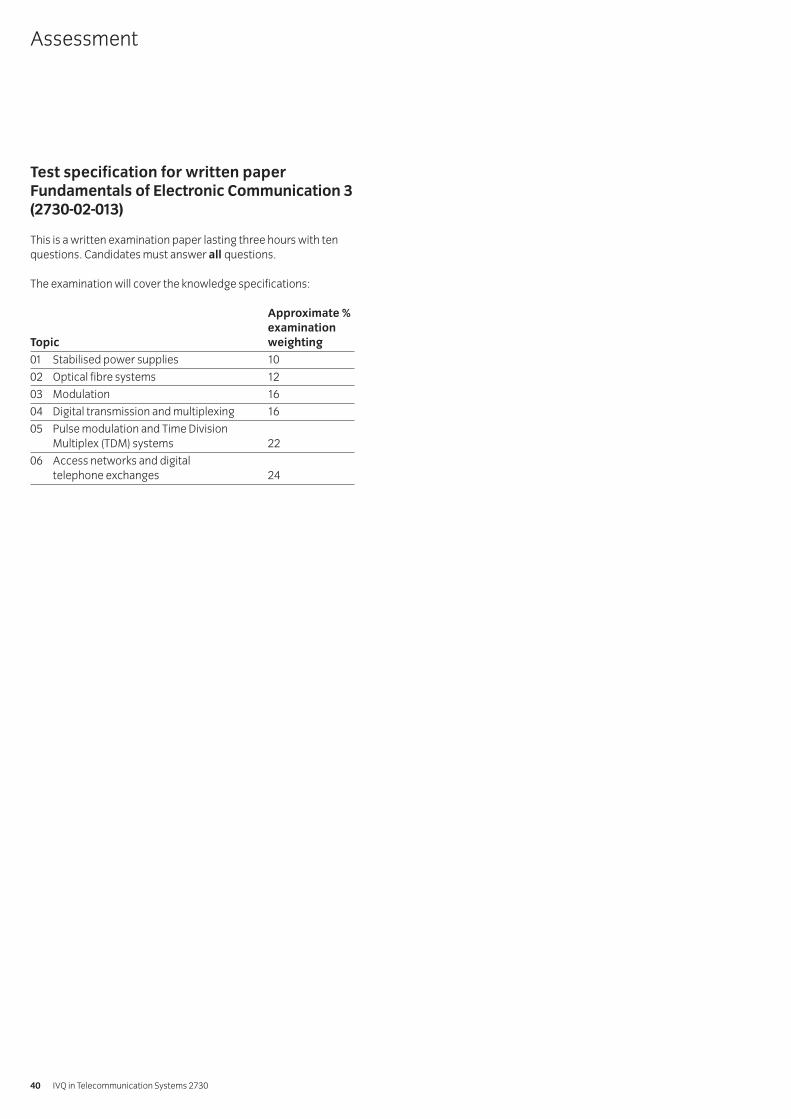
Test specification for written paperFundamentals of Electronic Communication 3(2730-02-013)
This is a written examination paper lasting three hours with tenquestions. Candidates must answer all questions.
The examination will cover the knowledge specifications:
Approximate %examination
Topic weighting
01 Stabilised power supplies 10
02 Optical fibre systems 12
03 Modulation 16
04 Digital transmission and multiplexing 16
05 Pulse modulation and Time Division Multiplex (TDM) systems 22
06 Access networks and digital telephone exchanges 24
Assessment
IVQ in Telecommunication Systems 273040
Introduction
The aim of this section is to enable the candidate to understand
a the importance of cabling in the overall framework of datacommunication
b the existence of international cabling standards and thebenefits of adhering to them
c how cabling installation practices affect the performance ofcabling infrastructure.
Notes:
1 It is suggested that about 15 guided learning hours should begiven to this section.
Book list
International Standard ISO/IEC 11801:2000Telecommunication Cabling Installation; BICSI.The Complete Guide to Network Wiring; David Groth and Jim McBee.
Practical competences
The candidate must be able to do the following:
1.1 Sketch a diagram illustrating a cabling design. The designmust comply with International StandardsOrganisation/International Electrotechnical Commission(ISO/IEC) 11801 standards.
1.2 Interpret link test results and compare with the relevantworst-case performance specifications.
1.3 Propose a standards based cabling solution based on abuilding plan.
1.4 Perform literature or Web search for information onevolving cabling standards.
1.5 Identify, make up and test typical network cables – fittingsuitable connectors (eg RJ45).
Knowledge requirements
The instructor must ensure the candidate is able to:
1.6 Explain the meaning of the term ‘structured cabling’ in the context of commercial premises cabling for data communication.
1.7 State that the ISO/IEC 11801 is a standard for genericcommercial premises cabling.Generic: not application specific
1.8 Explain what the ISO/IEC 11801 standard states and givereasons why the standard was formulated.Reasons: voice/data applications support-now and future, multiproduct, multivendor, ease of moves andchanges, generic
1.9 List the elements that make up the generic cabling systemand describe their function.Elements: campus, building, horizontal cabling,telecommunications outlet, telecommunications closetand equipment room
1.10 Demonstrate familiarity with generic cabling terminologyand their meanings as used in the ISO/IEC 11801 standard.Terminology: Floor Distributor (FD), Building Distributor(BD), Campus Distributor (CD), Telecommunication Outlet(TO), Transition Point (TP)
1.11 Demonstrate knowledge of different media typesrecognised by the ISO/IEC 11801 standard.Media types: 4-pair (or 2-pair) 100 Ω (or 120 Ω) balancedcable, 62.5/125 µm (or 50/125 µm) optical fibre, 2-pair 150Ω Shielded Twisted Pair (STP), single mode optical fibre
1.12 Understand that different building pathways require adifferent type of cable.Different: plenum cable requires higher fire rating
1.13 Demonstrate an understanding of cable performance terminology.Terminology: bandwidth, propagation delay, delay skew,attenuation, Attenuation-to-Crosstalk Ratio (ACR)
1.14 Describe some installation practices as stipulated by theISO/IEC 11801 standard.
1.15 Describe link performance and state that link performancecomponents and cables are defined as categories but thatthe link is defined as falling into one of the defined classes.Categories: 3, 5, 5e, 6Classes: A, B, C, D, E, F
1.16 Explain the importance of conformance testing of installed cabling.
1.17 Understand that testing is accomplished using calibratedtest equipment that conforms to the cabling testequipment standard.Standards: ISO/IEC 14763-3 and 61935-1
1.18 List parameters that are tested in link performance testsand explain their meaning.Parameters: Near End Crosstalk (NEXT), Far End Crosstalk(FEXT), Equal Level Far End Crosstalk (ELFEXT), Power SumNext (PSNEXT), return loss
1.19 Understand the importance of properly documenting theinstalled network in accordance with the guidelinesoutlined in the ISO/IEC 14763-1 standard.
014 Communication Systems and Digital Networks 301 Structured cabling
Syllabus: 2003 edition 41
Introduction
The aim of this section is to enable the candidate to
a understand the basic concepts of LANs, MANs and WANsb compare and contrast the different technologies used to
implement LANs, MANs and WANs.
Notes:
1 It is suggested that about 20 guided learning hours should begiven to this section.
Book list
Building a Network: How to Specify, Design, Procure, and Install aCorporate LAN; Peter D. Rhodes.Data & Computer Communications (6th edition); William Stallings.A Guide to Designing and Implementing Local and Wide AreaNetworks; Michael J. Palmer and Bruce Sinclair.Introduction to Data Communications and Networking; BehrouzForouzan, Catherine Ann Coombs, Sophia Chung Fegan.
Practical competences
The candidate must be able to do the following:
2.1 Conduct a literature or Web research of networkequipment products.
2.2 Use a network simulator to investigate LAN activity in agiven scenario.Network simulator: Cnet, OpnetActivity: traffic flow, protocol comparison, troubleshoot
2.3 Construct two LANs and establish a link between themutilising WAN technologies.
2.4 Calculate bandwidth requirements for a given LAN design.
2.5 Implement backup procedures.
2.6 Implement changes to a small LAN.
2.7 Recognise peer-to-peer and client-server configurations.
Knowledge requirements
The instructor must ensure the candidate is able to:
2.8 Define the terms LAN, MAN and WAN.
2.9 Explain the difference between broadcast-media-accessand non-broadcast-media-access technologies.
2.10 State the various shared media LAN technologies in usetoday and their operating speeds.Technologies: Ethernet, token ring, Fibre DistributedData Interface (FDDI), fast Ethernet, gigabit Ethernet
2.11 Describe how Ethernet and token ring technologies workand explain the terms half and full duplex.
2.12 Describe LAN topologies.Topologies: bus, tree, ring and star, extended star
2.13 Describe the role of hubs, switches, routers and NetworkInterface Cards (NICs) in a LAN.
2.14 Reference the International Standards Organisation(ISO)/Open System Interconnect (OSI) model and explain atwhich layers the equipment in 2.13 operate.Layers: data link, network
2.15 Explain the cause and effect of congestion on a network.Cause: increased traffic, high demand for accessEffect: increased collisions, slow response, time-outs
2.16 List factors that will reduce the total throughput of datawithin a LAN or reduce the bandwidth available for eachindividual node.Factors: Ethernet collisions, high volume of users,broadcast storms, inadequate physical segmentation,increased traffic, data backup procedures, faulty cabling,Electro Magnetic Interference (EMI)
2.17 Identify the different transmission media deployed in LANs.Media: Shielded Twisted Pair (STP), Unshielded TwistedPair (UTP), coaxial cable, optical fibre, wireless
2.18 State typical areas covered by LANs.Typical areas: a company site, a home, an office
2.19 State that a network, which serves multiple sites within acity’s limits or a metropolitan boundary, would be referredto as a MAN.
2.20 Identify the technologies used to implement MANs.Technologies: line-of-sight microwave, SynchronousDigital Hierarchy (SDH), leased line
2.21 State the technologies used in implementing WANs.Technologies: Frame Relay, Asynchronous Transfer Mode (ATM)
2.22 Provide examples of MANs.Examples: university campus, local government offices
2.23 Provide examples of a WAN.Examples: a company operating networked offices inTokyo and Osaka, an international company with offices inseveral countries
2.24 Explain the Institute of Electrical and Electronic Engineers(IEEE) 802 standards for LAN access control.Standards: 802.3 Carrier Sensing Multiple Access/ CollisionDetection (CSMA/CD), Medium Access Control (MAC)
014 Communication Systems and Digital Networks 302 Local Area Networks (LANs), Metropolitan Area Networks (MANs) andWide Area Networks (WANs)
IVQ in Telecommunication Systems 273042
Introduction
The aim of this section is to enable the candidate to understand
a the different transmission media availableb why optical fibre is replacing coaxial cable on long
haul networksc the various digital carrier systems in use todayd data multiplexing methods for utilising bandwidth.
Notes:
1 It is suggested that about 20 guided learning hours should begiven to this section.
Book list
SONET/SDH Demystified; Steven Shepard.
Practical competences
The candidate must be able to do the following:
3.1 Produce a report investigating the use of DenseWavelength Division Multiplexing (DWDM) techniques.
3.2 Conduct Web and literature review on ITU-T standards onSynchronous Digital Hierarchies (SDH) and AmericanNational Standards Institute (ANSI) Synchronous OpticalNetwork (SONET) standards.
3.3 Draw a diagram illustrating the SDH system.
Knowledge requirements
The instructor must ensure the candidate is able to:
3.4 Describe the different data transmission media currently in use.Media: twisted pair, coaxial cable, optical fibre, radio
3.5 Explain the data carrying capacity provided by optical fibreand the potential that exists when Wavelength DivisionMultiplexing (WDM) is used.
3.6 Explain that transmission systems need to be reliable,resilient and flexible because they serve many customers.
3.7 Briefly explain the meaning of the terms ‘synchronous’,‘asynchronous’ and ‘plesiochronous’ signals.
3.8 Explain the basic operating principles of synchronous time division multiplexing and statistical time divisionmultiplexing.
3.9 Describe the digital carrier systems in use today.
3.10 Explain Plesiochronous Digital Hierarchy (PDH) (ITU-TG.702) systems and highlight their disadvantages.
3.11 Briefly explain what SONET and SDH are and whatnecessitated their development.
3.12 Describe types of traffic that can be transported overSONET/SDH.Traffic: voice, IP packets, ATM cells
3.13 Describe the operation of add/drop multiplexers.
3.14 Describe how the various classes of PDH traffic can betransported by the level one Synchronous TransportModule (STM-1).PDH traffic: 1.5, 2, 6, 34, 45 and 140 Mbps
3.15 Explain the function of virtual containers in the SDHmultiplex system.
3.16 Describe the structure of the ITU-T G.707 SDH model.Structure: STM-1 = 155.52 Mbps, STM-4 = 622.08 Mbps,STM-8 = 1.2416 Gbps, STM-12 = 1.86624, STM-16 = 2.48832Gbps etc.
014 Communication Systems and Digital Networks 303 Transmission systems
Syllabus: 2003 edition 43
Introduction
The aim of this section is to enable the candidate to
a develop an awareness of systems, which are positioned atthe end of networks
b appreciate ergonomics and user-friendly man machineinterfaces for computer equipment and networked devices
c select appropriate hardware for a given need.
Notes:
1 It is suggested that about 10 guided learning hours should begiven to this section.
Book list
Practical Network Design, Management and Troubleshooting; J. Scott Haugdahl.Top-down Network Design; Priscilla Oppenheimer.
Practical competences
The candidate must be able to do the following:
4.1 Identify parameters that determine the suitability of oneend system over another.Parameters: total cost of ownership, reliability,compatibility, vendor loyalties, political correctness,performance benchmarks
4.2 Conduct a literature and Web research on vendor endsystems and international standards relating to endsystems technologies.
Knowledge requirements
The instructor must ensure the candidate is able to:
4.3 Demonstrate a comprehension of the evolution of thetechnologies, which support end systems.End systems: telephones, personal computers (PCs),Electronic Point of Sales (EPOSs), Automatic TellerMachines (ATM), printers, entry systems
4.4 Identify methods of connecting equipment to a network.Methods: cable, wireless, infrared, bluetooth
4.5 Describe user-friendly systems connected to networks.User-friendly systems: Graphical User Interface (GUI),touch screens, fingerprint recognition, iris recognition
4.6 Compare command line based systems to GUI based systems.
4.7 Describe mainframe computer systems.
4.8 Identify the main differences and similarities betweenmainframe and clientserver networks.
4.9 Describe client-server computer systems and compare a clientserver computer system to a peer-to-peer computer system.
4.10 Explain web-server technologies and identify softwarewhich provides web-server services, briefly mentioningserver-side and client-side solutions.Server-side solution: Common Gateway Interface (CGI)Client-side solution: JavaScript
4.11 Explain telephone technologies including Voice OverInternet Protocol (VOIP).
4.12 State the advantages of VOIP over conventional telephone systems.
4.13 Describe the possible issues which relate to theimplementation of VOIP.Issues: PBX to PBX, total Internet Protocol (IP) solution,integration with legacy systems, Quality of Service (QoS),latency, jitter
4.14 Demonstrate an awareness of current and emergingtechnologies, which relate to endsystems in various fields.Fields: audio and video signal processing, broadcastsystems, surveillance systems, telemetry, flight control
4.15 Describe the effect that Information and Communication Technologies (ICTs) have had upon society and the individual.
014 Communication Systems and Digital Networks 304 End systems
IVQ in Telecommunication Systems 273044
Introduction
The aim of this section is to enable the candidate to understand
a general concepts of network managementb techniques to monitor, control and maintain network trafficc methods of network administrationd network management protocols, Simple Network
Management Protocol (SNMP)e security issues relating to the performance and general well-
being of a network.
Notes:
1 It is suggested that about 23 guided learning hours should begiven to this section.
Book list
Network Troubleshooting Tools (O’Reilly System Administration);Joseph D. Sloan.Practical Network Design, Management and Troubleshooting; J.Scott Haugdahl.Snmp, Snmpv2, Snmpv3, and Rmon 1 and 2; William Stallings.
Practical competences
The candidate must be able to do the following:
5.1 Identify tools, which can be deployed for networkmanagement.
5.2 Perform essential administrative network tasks.Tasks: monitor traffic, maintain documentation,optimisation of network
5.3 Use software tools to monitor network traffic.Tools: protocol analysers, network analysers
5.4 Interpret results presented by the tools.Results: collisions, traffic loading, points of failure
5.5 Enable management capability of hardware.
5.6 Conduct literature and Web search for information relatingto network management.
Knowledge requirements
The instructor must ensure the candidate is able to:
5.7 Describe the issues that relate to the management of acomputer network.Issues: traffic flow, security, performance monitoring,fault detection, problem solving
5.8 Explain that with larger and more complex networks, useof automated management tools becomes imperative.
5.9 Define a Network Management System (NMS).NMS: collection of tools for network monitoring and control
5.10 Describe the elements of an NMS.Elements: management stations, agents, ManagementInformation Base (MIB), network management protocol
5.11 Explain the function of MIBs.Function: a collection of access points with agents, which report to the management station
5.12 List and describe the operation of network management protocols.Protocols: Remote MONitoring (RMON), Simple NetworkManagement Protocol (SNMP)
5.13 Describe the reporting mechanism of management protocols.
5.14 Explain the differences between RMON and SNMP.
5.15 List equipment that can be remotely managed.Equipment: SNMP compliant hubs, switches, routers,personal computers (PCs), modems, intelligent patch panels
5.16 Explain the terms commonly associated with the reliabilityof systems.Terms: availability, mean-time-between-failures (mtbf),mean-time-to-repair (mttr), up time, down time, useful life cycle
5.17 Calculate the system/network availability given figures formtbf and mttr.
5.18 Explain that management software can remotely alter theoperating parameters of hardware, in addition tomonitoring the network.Parameters: Virtual Local Area Network (VLAN)membership, performance thresholds
5.19 Cite examples of network management software.Management software: HP OpenView, Solstice SunnetManager (SSM), BMC patrol
5.20 Outline the security issues that relate to networkmanagement.Security issues: eavesdropping, intrusion, spoofing,hackers, viruses
5.21 Explain why it is important to have a network wide securitypolicy, including measures to counteract attacks in theform of software viruses.
014 Communication Systems and Digital Networks 305 Network management
Syllabus: 2003 edition 45

5.22 Describe the implications of a compromised networkreferencing network security issues.
5.23 Explain that encryption is an example of a way ofcountering security threats.Encryption: scrambling of data so that it is unintelligibleto unauthorised parties
5.24 Explain the role of antiviral software in the overallframework of network management.
IVQ in Telecommunication Systems 273046
Introduction
The aim of this section is to enable the candidate to
a define the basic configuration and operation for an IDCb understand the infrastructure necessary for an IDCc identify the routine maintenance tasks of an IDCd comprehend the security issues which relate to an IDC.
Notes:
1 It is suggested that about 17 guided learning hours shouldbe given to this section.
Book list
Enterprise Data Center Design and Methodology; Rob Snevely.
Practical competences
The candidate must be able to do the following:
6.1 Identify hardware necessary to operate an IDC.Hardware: routers, switches, backup devices, accessservers, web servers, Uninterrupted Power Supply (UPS)
6.2 Conduct a literature and Web research for vendor IDC solutions.
Knowledge requirements
The instructor must ensure the candidate is able to:
6.3 Outline services offered by an IDC.Services: Internet access, connectivity, data storage, co-location
6.4 List the considerations for setting up an IDC.Considerations: infrastructure, management tools,operating systems, operating network hardware,computing hardware
6.5 Understand the basics of the technologies used within anIDC operation.Technologies: modem, Integrated Services DigitalNetwork (ISDN) access, server clustering, load-balancing,data backup systems, fibre channel, traffic shaping
6.6 Recognise the importance of taking into account the effectof unplanned downtime on IDC operations during theplanning stage.
6.7 Recognise security issues within an IDC.Security issues: confidentiality, virus protection, dataprotection act, encryption, physical access
6.8 List and describe methods of improving security.Methods: data encryption, high-level physical accesscontrol to buildings, antivirus measures
6.9 Identify the facilities required by an IDC, which will enableefficient operation.Facilities: Heat Ventilation Air-Conditioning (HVAC),physical security, fire suppression systems, seismic proof,waterproof, terrorist proof
6.10 Realise the advantage of being located near major public and private interconnects, in order to maximise site performance.Advantage: access to high-speed data links
6.11 Explain the function of a network firewall in an IDC.Firewall: data filtering
6.12 Explain the various options for managed hosting offered by an IDC.Options: virtual Internet Service Provider (ISP), co-hosting
6.13 State different customer’s access methods to the IDC.Methods: Public Switched Telephone Network (PSTN),ISDN, x Digital Subscriber Line (xDSL), leased lines
6.14 Identify the issues which affect customer connectivity tothe Internet.Issues: bandwidth, user access ratios, traffic congestion
6.15 Describe the factors that affect the continuity of services.Factors: 24-hour management systems, redundancy,managed power supply, multiple backup, off-site databackups
014 Communication Systems and Digital Networks 306 Internet Data Centre (IDC)
Syllabus: 2003 edition 47
Test specification for written paperCommunication Systems and DigitalNetworks 3 (2730-02-014)
This is a written examination paper lasting three hours with tenquestions. Candidates must answer all questions.
The examination paper will cover the knowledge specifications:
Approximate %examination
Topic weighting
01 Structured cabling 16
02 Local Area Networks (LANs), Metropolitan Area Networks (MANs)and Wide Area Networks (WANs) 20
03 Transmission systems 12
04 End systems 16
05 Network management 20
06 Internet Data Centre (IDC) 16
Assessment
IVQ in Telecommunication Systems 273048
Practical assignments
Fundamentals of Electronic Communication 2Assignment 015/1: Boolean circuits and gatesAssignment 015/2: Impedance and decibels
Communication Systems and Digital Networks 2Assignment 015/3: Data communicationAssignment 015/4: Transmission Control Protocol / Internet
Protocol (TCP/IP) – network addressconfiguration
Assignment 015/5: Router configuration, documentation,Transmission Control Protocol / InternetProtocol (TCP/IP) and the Open SystemsInterconnect (OSI) layer models
Fundamentals of Electronic Communication 3Assignment 015/6: Modem design and characteristicsAssignment 015/7: Historical and practical aspects of
telephone networks
Communication Systems and Digital Networks 3Assignment 015/8: Structured CablingAssignment 015/9: Designing a Local Area Network (LAN),
Metropolitan Area Network (MAN) and WideArea Network (WAN) solution
Assignment 015/10: Synchronous Optical Network (SONET)Assignment 015/11: Designing endsystems for a Small to Medium
sized Enterprise (SME)Assignment 015/12: Network management tools
015 Telecommunication Systems Practice 2/3
Syllabus: 2003 edition 49
1 Objective references
2730-02-011: 2.1
2 Preparation
2.1 Location of the testThe training centre or other venue where supervision andappropriate working conditions will be provided.
2.2 RequirementsAnswer books.
Handout showing LED circuit and logical gates.
5 volt d.c. supply.
Three 680 ohm resistors.
Six TTL Logic Gates (1 NOR, 2 EXOR, 3 NAND) and 3 LEDs (1yellow, 1 green, 1 red).
2.3 Instructor notesThe aim of this assignment is to encourage candidates toapply the laws of Boolean algebra and to construct andinvestigate an electrical circuit consisting of logic gatesand Light Emitting Diodes (LEDs).
Candidates must be familiar with setting up simpleelectrical circuits. The time candidates are given for thistask is three hours. All tasks should be completed withinthe allocated time.
3 Candidates’ instructions
3.1 The time allowed for this assignment is three hours. Theassignment is divided into two parts. You are advised toread the instructions carefully before commencing anywork. Ensure that you understand all the practicalinstructions and follow them precisely. If you are in anydoubt ask your instructor.
Part 13.2 Using the laws of Boolean algebra, verify that the
Boolean expressionB .B
–+ A . (A
–+ B.A)
simplifies to the expressionA . B
3.3 Draw a simple switch circuit to represent the originalexpression given in 3.2, and also a separate switch circuitto represent the simpler expression given in 3.2.
3.4 Explain carefully why the operation of the simpler circuit isequivalent to that of the original.
Part 23.5 Construct the circuit shown in section 6.1, leaving the
connection of the d.c. supply unit until the end. Note thatR1, R2 and R3 are 680 ohms.
3.6 Turn on the supply and record the sequence of colours which occurs on the LEDs, when each of the three inputs (A, B and C) are selected in the order given in the truth table.
3.7 Explain how this sequence arises, by completing the blanktable in section 6.1. (You may use the truth tables providedfor the NOR, EXOR and NAND gates to assist you in this.)
3.8 Hand in all documentation to your instructor in the time allocated. Ensure that all your written work is clearly presented.
Practical assignments – Fundamentals of Electronic Communication 2Practical assignment 015/1: Boolean circuits and gates
IVQ in Telecommunication Systems 273050
4 Marking
Part 14.1 Assignment completed within three hours. ( )
4.2 Correctly explained simplification of the given Boolean expression. ( )
4.3 Correctly drawn Boolean switch circuits for the two expressions. [ ]
4.4 Concise, correct explanation of the equivalent behaviour of both the original and simplified Boolean circuits. [ ]
Part 24.5 Correct connection of the LED/gate circuit. [ ]
4.6 Correct sequencing behaviour of the LED/gate circuit. ( )
4.7 Correct explanation of the lighting sequence. [ ]
4.8 Documentation handed in to the instructor. [ ]
5 Assignment completion
The candidate will have satisfactorily completed thisassignment if successful in all items marked with a [ ] and atleast one of the items marked with a ( ). A period of seven days must elapse before an unsuccessfulcandidate may retake this assignment.
Syllabus: 2003 edition 51
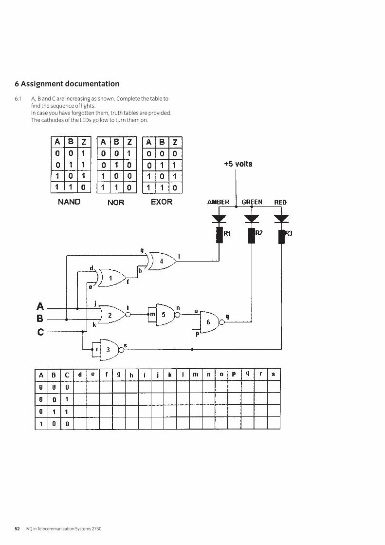
6 Assignment documentation
6.1 A, B and C are increasing as shown. Complete the table tofind the sequence of lights.In case you have forgotten them, truth tables are provided.The cathodes of the LEDs go low to turn them on.
IVQ in Telecommunication Systems 273052
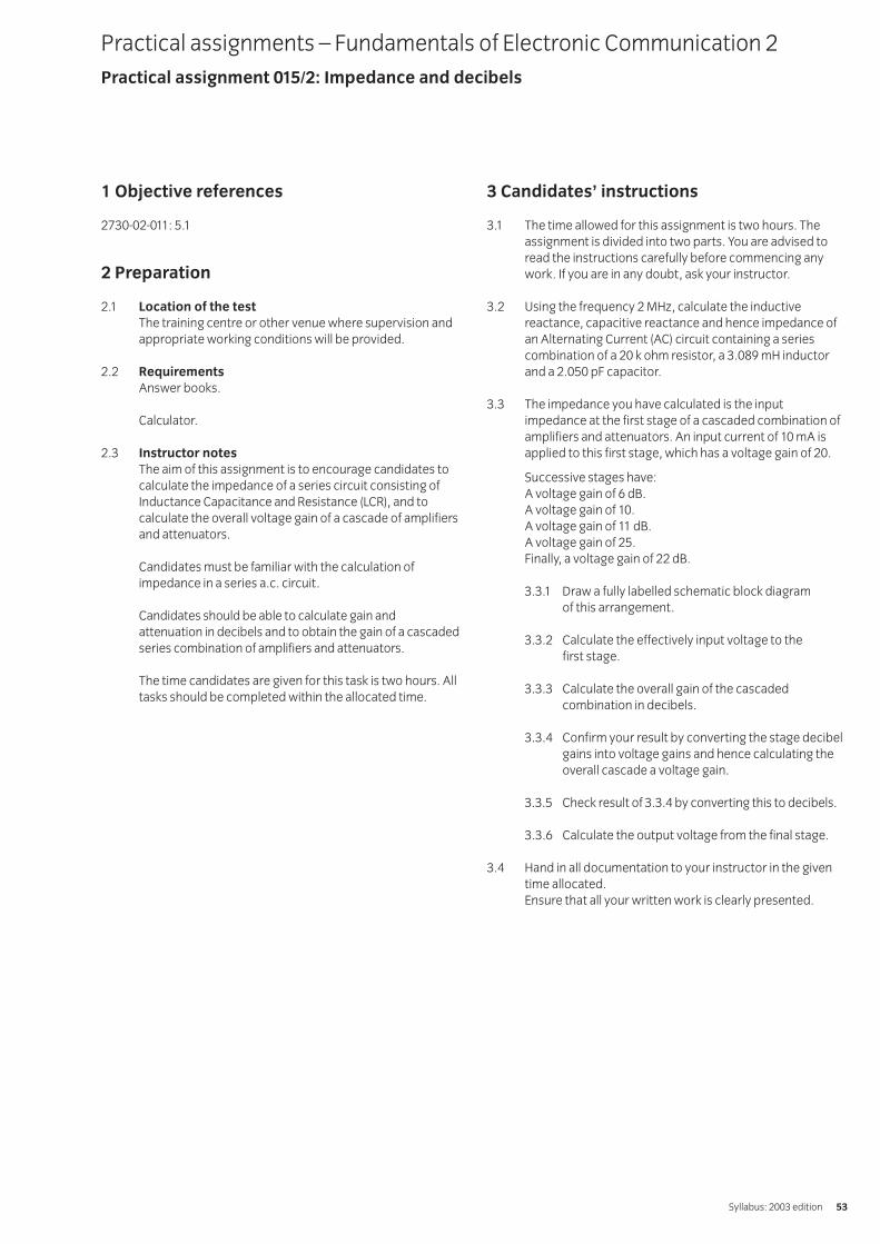
1 Objective references
2730-02-011: 5.1
2 Preparation
2.1 Location of the testThe training centre or other venue where supervision andappropriate working conditions will be provided.
2.2 RequirementsAnswer books.
Calculator.
2.3 Instructor notesThe aim of this assignment is to encourage candidates tocalculate the impedance of a series circuit consisting ofInductance Capacitance and Resistance (LCR), and tocalculate the overall voltage gain of a cascade of amplifiersand attenuators.
Candidates must be familiar with the calculation ofimpedance in a series a.c. circuit.
Candidates should be able to calculate gain andattenuation in decibels and to obtain the gain of a cascadedseries combination of amplifiers and attenuators.
The time candidates are given for this task is two hours. Alltasks should be completed within the allocated time.
3 Candidates’ instructions
3.1 The time allowed for this assignment is two hours. Theassignment is divided into two parts. You are advised toread the instructions carefully before commencing anywork. If you are in any doubt, ask your instructor.
3.2 Using the frequency 2 MHz, calculate the inductivereactance, capacitive reactance and hence impedance ofan Alternating Current (AC) circuit containing a seriescombination of a 20 k ohm resistor, a 3.089 mH inductorand a 2.050 pF capacitor.
3.3 The impedance you have calculated is the inputimpedance at the first stage of a cascaded combination ofamplifiers and attenuators. An input current of 10 mA isapplied to this first stage, which has a voltage gain of 20.
Successive stages have:A voltage gain of 6 dB.A voltage gain of 10.A voltage gain of 11 dB.A voltage gain of 25.Finally, a voltage gain of 22 dB.
3.3.1 Draw a fully labelled schematic block diagram of this arrangement.
3.3.2 Calculate the effectively input voltage to the first stage.
3.3.3 Calculate the overall gain of the cascadedcombination in decibels.
3.3.4 Confirm your result by converting the stage decibelgains into voltage gains and hence calculating theoverall cascade a voltage gain.
3.3.5 Check result of 3.3.4 by converting this to decibels.
3.3.6 Calculate the output voltage from the final stage.
3.4 Hand in all documentation to your instructor in the giventime allocated. Ensure that all your written work is clearly presented.
Practical assignments – Fundamentals of Electronic Communication 2Practical assignment 015/2: Impedance and decibels
Syllabus: 2003 edition 53
4 Marking
4.1 Assignment completed within two hours. ( )
4.2 Correct calculations of inductive reactance, capacitivereactance and impedance of the series combination at the frequency given. [ ]
4.3 Answers for 3.2 applied to cascadingamplifiers/attenuators:
4.3.1 Labelled block schematic diagram drawn. ( )
4.3.2 Correct calculation of input voltage to first stage. [ ]
4.3.3 Correct calculation of overall gain in decibels. [ ]
4.3.4 Correct calculation of individual voltage gains, and hence overall voltage gain. ( )
4.3.5 Conversion check confirms result. ( )
4.3.6 Correct calculation of output voltage of final stage. ( )
4.4 Diagram and calculations handed in to the instructor. [ ]
5 Assignment completion
The candidate will have satisfactorily completed thisassignment if successful in all items marked with a [ ] and atleast one of the items marked with a ( ).
A period of seven days must elapse before an unsuccessfulcandidate may retake this assignment.
IVQ in Telecommunication Systems 273054
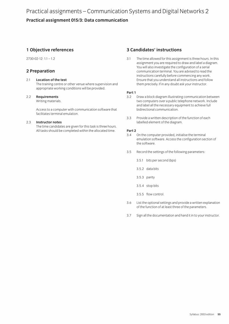
1 Objective references
2730-02-12: 1.1 – 1.2
2 Preparation
2.1 Location of the testThe training centre or other venue where supervision andappropriate working conditions will be provided.
2.2 RequirementsWriting materials.
Access to a computer with communication software thatfacilitates terminal emulation.
2.3 Instructor notesThe time candidates are given for this task is three hours.All tasks should be completed within the allocated time.
3 Candidates’ instructions
3.1 The time allowed for this assignment is three hours. In thisassignment you are required to draw and label a diagram.You will also investigate the configuration of a serialcommunication terminal. You are advised to read theinstructions carefully before commencing any work.Ensure that you understand all instructions and followthem precisely. If in any doubt ask your instructor.
Part 13.2 Draw a block diagram illustrating communication between
two computers over a public telephone network. Includeand label all the necessary equipment to achieve fullbidirectional communication.
3.3 Provide a written description of the function of eachlabelled element of the diagram.
Part 23.4 On the computer provided, initialise the terminal
emulation software. Access the configuration section ofthe software.
3.5 Record the settings of the following parameters:
3.5.1 bits per second (bps)
3.5.2 data bits
3.5.3 parity
3.5.4 stop bits
3.5.5 flow control.
3.6 List the optional settings and provide a written explanationof the function of at least three of the parameters.
3.7 Sign all the documentation and hand it in to your instructor.
Practical assignments – Communication Systems and Digital Networks 2Practical assignment 015/3: Data communication
Syllabus: 2003 edition 55
4 Marking
4.1 Assignment completed in three hours. ( )
Part 14.2 Accurate block diagram drawn and labelled. [ ]
4.3 A written description of the function of each labelledelement provided. [ ]
Part 24.4 Terminal software initialised. Configuration
section accessed. [ ]
4.5 Setting of following parameters recorded:
4.5.1 bits per second (bps). ( )
4.5.2 data bits. ( )
4.5.3 parity. ( )
4.5.4 stop bits. ( )
3.5.5 flow control. ( )
4.6 Settings listed. Written explanation of the function of at least three parameters provided. [ ]
4.7 All documentation handed in to the instructor. [ ]
5 Assignment completion
The candidate will have satisfactorily completed thisassignment if successful in all items marked with a [ ] and atleast three of the items marked with a ( ).
A period of seven days must elapse before an unsuccessfulcandidate may retake this assignment.
IVQ in Telecommunication Systems 273056
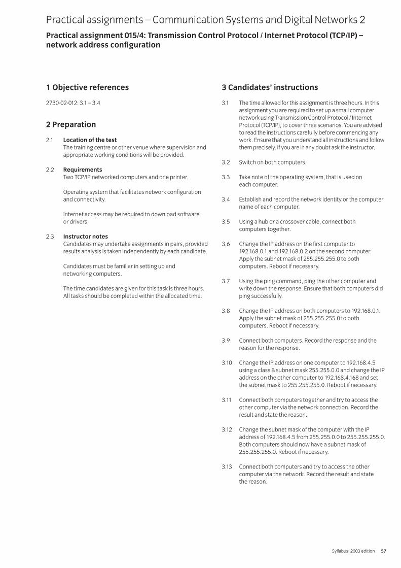
1 Objective references
2730-02-012: 3.1 – 3.4
2 Preparation
2.1 Location of the testThe training centre or other venue where supervision andappropriate working conditions will be provided.
2.2 RequirementsTwo TCP/IP networked computers and one printer.
Operating system that facilitates network configurationand connectivity.
Internet access may be required to download software or drivers.
2.3 Instructor notesCandidates may undertake assignments in pairs, providedresults analysis is taken independently by each candidate.
Candidates must be familiar in setting up and networking computers.
The time candidates are given for this task is three hours.All tasks should be completed within the allocated time.
3 Candidates’ instructions
3.1 The time allowed for this assignment is three hours. In thisassignment you are required to set up a small computernetwork using Transmission Control Protocol / InternetProtocol (TCP/IP), to cover three scenarios. You are advisedto read the instructions carefully before commencing anywork. Ensure that you understand all instructions and followthem precisely. If you are in any doubt ask the instructor.
3.2 Switch on both computers.
3.3 Take note of the operating system, that is used on each computer.
3.4 Establish and record the network identity or the computername of each computer.
3.5 Using a hub or a crossover cable, connect both computers together.
3.6 Change the IP address on the first computer to 192.168.0.1 and 192.168.0.2 on the second computer.Apply the subnet mask of 255.255.255.0 to bothcomputers. Reboot if necessary.
3.7 Using the ping command, ping the other computer andwrite down the response. Ensure that both computers didping successfully.
3.8 Change the IP address on both computers to 192.168.0.1.Apply the subnet mask of 255.255.255.0 to bothcomputers. Reboot if necessary.
3.9 Connect both computers. Record the response and thereason for the response.
3.10 Change the IP address on one computer to 192.168.4.5using a class B subnet mask 255.255.0.0 and change the IPaddress on the other computer to 192.168.4.168 and setthe subnet mask to 255.255.255.0. Reboot if necessary.
3.11 Connect both computers together and try to access theother computer via the network connection. Record theresult and state the reason.
3.12 Change the subnet mask of the computer with the IPaddress of 192.168.4.5 from 255.255.0.0 to 255.255.255.0.Both computers should now have a subnet mask of255.255.255.0. Reboot if necessary.
3.13 Connect both computers and try to access the othercomputer via the network. Record the result and state the reason.
Practical assignments – Communication Systems and Digital Networks 2Practical assignment 015/4: Transmission Control Protocol / Internet Protocol (TCP/IP) –network address configuration
Syllabus: 2003 edition 57
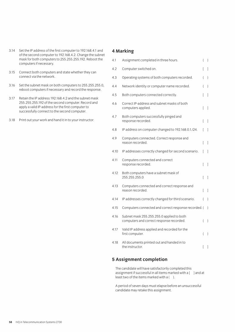
3.14 Set the IP address of the first computer to 192.168.4.1 andof the second computer to 192.168.4.2. Change the subnetmask for both computers to 255.255.255.192. Reboot thecomputers if necessary.
3.15 Connect both computers and state whether they canconnect via the network.
3.16 Set the subnet mask on both computers to 255.255.255.0,reboot computers if necessary and record the response.
3.17 Retain the IP address 192.168.4.2 and the subnet mask255.255.255.192 of the second computer. Record andapply a valid IP-address for the first computer tosuccessfully connect to the second computer.
3.18 Print out your work and hand it in to your instructor.
4 Marking
4.1 Assignment completed in three hours. ( )
4.2 Computer switched on. [ ]
4.3 Operating systems of both computers recorded. ( )
4.4 Network identity or computer name recorded. ( )
4.5 Both computers connected correctly. [ ]
4.6 Correct IP-address and subnet masks of both computers applied. [ ]
4.7 Both computers successfully pinged and response recorded. [ ]
4.8 IP address on computer changed to 192.168.0.1./24. [ ]
4.9 Computers connected. Correct response and reason recorded. [ ]
4.10 IP addresses correctly changed for second scenario. [ ]
4.11 Computers connected and correct response recorded. [ ]
4.12 Both computers have a subnet mask of 255.255.255.0 [ ]
4.13 Computers connected and correct response and reason recorded. [ ]
4.14 IP addresses correctly changed for third scenario. ( )
4.15 Computers connected and correct response recorded. ( )
4.16 Subnet mask 255.255.255.0 applied to both computers and correct response recorded. ( )
4.17 Valid IP address applied and recorded for the first computer. ( )
4.18 All documents printed out and handed in to the instructor. [ ]
5 Assignment completion
The candidate will have satisfactorily completed thisassignment if successful in all items marked with a [ ] and atleast two of the items marked with a ( ).
A period of seven days must elapse before an unsuccessfulcandidate may retake this assignment.
IVQ in Telecommunication Systems 273058
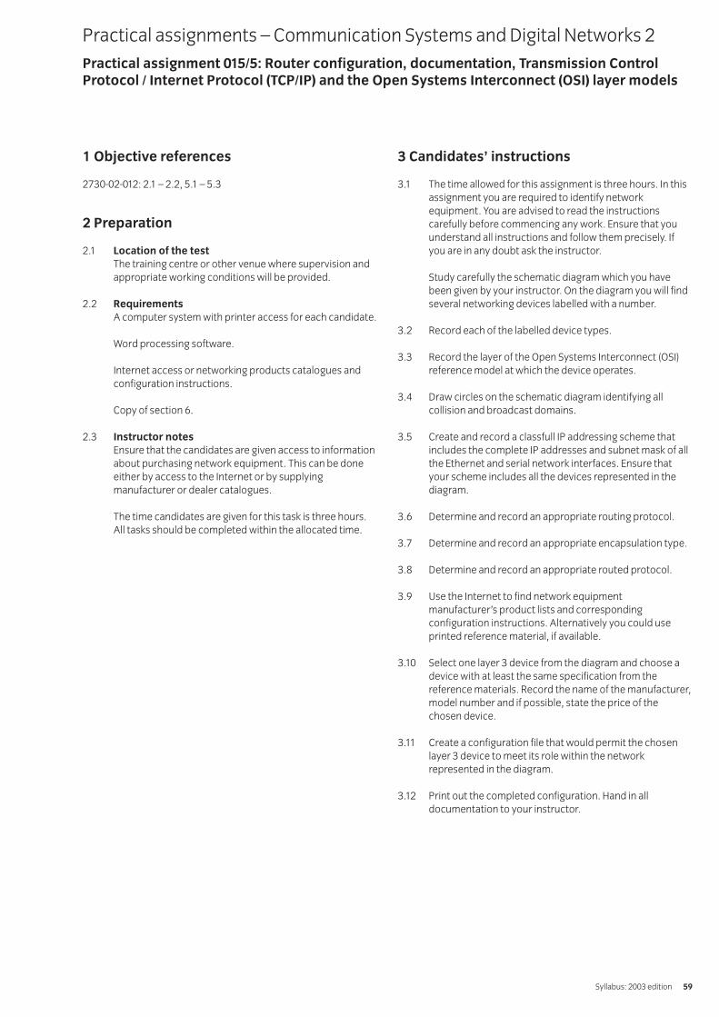
1 Objective references
2730-02-012: 2.1 – 2.2, 5.1 – 5.3
2 Preparation
2.1 Location of the testThe training centre or other venue where supervision andappropriate working conditions will be provided.
2.2 RequirementsA computer system with printer access for each candidate.
Word processing software.
Internet access or networking products catalogues andconfiguration instructions.
Copy of section 6.
2.3 Instructor notesEnsure that the candidates are given access to informationabout purchasing network equipment. This can be doneeither by access to the Internet or by supplyingmanufacturer or dealer catalogues.
The time candidates are given for this task is three hours.All tasks should be completed within the allocated time.
3 Candidates’ instructions
3.1 The time allowed for this assignment is three hours. In thisassignment you are required to identify networkequipment. You are advised to read the instructionscarefully before commencing any work. Ensure that youunderstand all instructions and follow them precisely. Ifyou are in any doubt ask the instructor.
Study carefully the schematic diagram which you havebeen given by your instructor. On the diagram you will findseveral networking devices labelled with a number.
3.2 Record each of the labelled device types.
3.3 Record the layer of the Open Systems Interconnect (OSI)reference model at which the device operates.
3.4 Draw circles on the schematic diagram identifying allcollision and broadcast domains.
3.5 Create and record a classfull IP addressing scheme thatincludes the complete IP addresses and subnet mask of allthe Ethernet and serial network interfaces. Ensure thatyour scheme includes all the devices represented in thediagram.
3.6 Determine and record an appropriate routing protocol.
3.7 Determine and record an appropriate encapsulation type.
3.8 Determine and record an appropriate routed protocol.
3.9 Use the Internet to find network equipmentmanufacturer’s product lists and correspondingconfiguration instructions. Alternatively you could useprinted reference material, if available.
3.10 Select one layer 3 device from the diagram and choose adevice with at least the same specification from thereference materials. Record the name of the manufacturer,model number and if possible, state the price of thechosen device.
3.11 Create a configuration file that would permit the chosenlayer 3 device to meet its role within the networkrepresented in the diagram.
3.12 Print out the completed configuration. Hand in alldocumentation to your instructor.
Practical assignments – Communication Systems and Digital Networks 2Practical assignment 015/5: Router configuration, documentation, Transmission ControlProtocol / Internet Protocol (TCP/IP) and the Open Systems Interconnect (OSI) layer models
Syllabus: 2003 edition 59
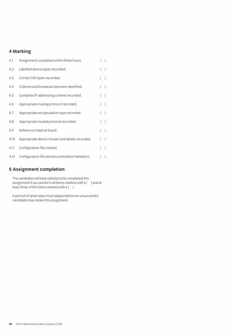
4 Marking
4.1 Assignment completed within three hours. ( )
4.2 Labelled device types recorded. ( )
4.3 Correct OSI layers recorded. [ ]
4.4 Collision and broadcast domains identified. [ ]
4.5 Complete IP addressing scheme recorded. [ ]
4.6 Appropriate routing protocol recorded. ( )
4.7 Appropriate encapsulation type recorded. ( )
4.8 Appropriate routed protocol recorded. ( )
4.9 Reference material found. [ ]
4.10 Appropriate device chosen and details recorded. [ ]
4.11 Configuration file created. [ ]
4.12 Configuration file and documentation handed in. [ ]
5 Assignment completion
The candidate will have satisfactorily completed thisassignment if successful in all items marked with a [ ] and atleast three of the items marked with a ( ).
A period of seven days must elapse before an unsuccessfulcandidate may retake this assignment
IVQ in Telecommunication Systems 273060
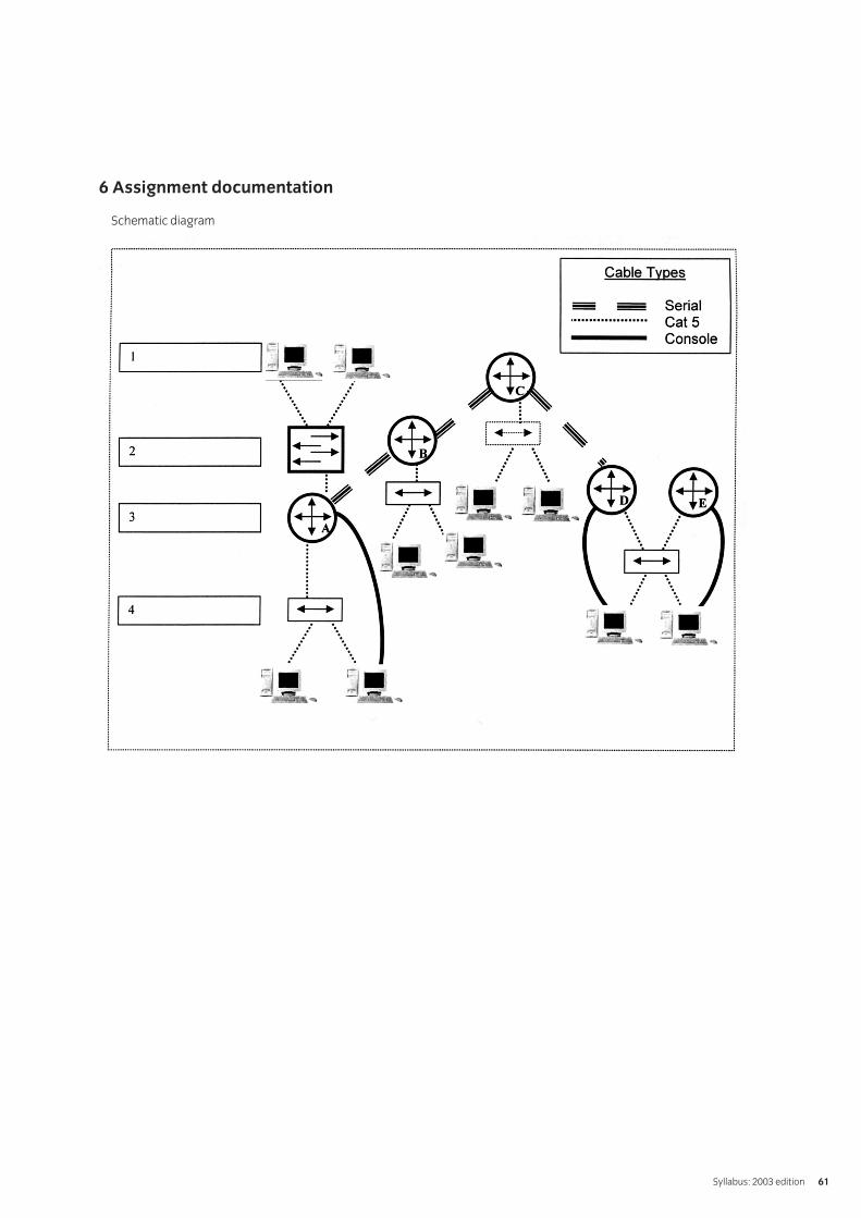
6 Assignment documentation
Schematic diagram
Syllabus: 2003 edition 61
1 Objective references
2730-02-013: 3.1, 4.1
2 Preparation
2.1 Location of the testThe training centre or other venue where supervision andappropriate working conditions will be provided.
2.2 RequirementsExternal modem with access to an analogue networkexchange (internal or external network).
Access to reference sources that contain up to date as wellas basic information on modems. Access to the Internetand/or printed manufacturers product lists would ensure arealistic response.
2.3 Instructor notesThe aim of this assignment is to encourage candidates to investigate the design characteristics of modems andanalyse the modulation schemes employed for the transfer of data.
Ensure that the candidates are given access to a pair ofworking modems with connections to internal or externaltelephone networks. Provide information about modems,this can be done either by access to the Internet or bysupplying manufacturer or dealer catalogues.
The time candidates are given for this task is three hours,not including the time needed to write up the report. Alltasks should be completed within the allocated time.
3 Candidates’ instructions
3.1 The time allowed for this assignment is three hours, notincluding the time needed to write up your report. In thisassignment you are required to investigate the modulationschemes employed for the serial transfer of digital dataover analogue networks (eg the PSTN) and to produce areport which covers your findings. You are advised to readthe instructions carefully before commencing any work.Ensure that you understand all instructions and followthem precisely. If you are in any doubt ask the instructor.
Part 13.2 Construct a modem link and communicate across an
analogue network.
3.3 Demonstrate modem interchange light emitting diodesoperating during a connection and describe the meaningof the signalling.
Part 23.4 Investigate the range of modulation schemes and
minimisation techniques employed in modern modemsand produce a report that covers:
3.4.1 The need for modems.
3.4.2 The function of the Data CommunicationsEquipment (DCE).
3.4.3 The function of the Data Terminal Equipment (DTE).
3.4.4 The role of the Hayes command set.
3.4.5 The type of communication links established (iewhether synchronous or asynchronous, duplex orhalf-duplex, symmetric or asymmetric).
3.4.6 The modulation schemes that can be employed for
3.4.6.1 low speed applications
3.4.6.2 medium speed applications
3.4.6.3 high speed applications.
3.7.7 How data transmission speeds in excess of theShannon-Hartley limit can be achieved.
3.7.8 The ITU-T (formerly CCITT) standards for modems.
3.7.9 The use of cable modems.
3.5 You should access a wide range of reference sources (textand web based) during your investigation.
3.6 Your report should list all sources of reference used.
3.7 Print out your work and hand it in to your instructor beforethe given deadline.
Practical assignments – Fundamentals of Electronic Communication 3Practical assignment 015/6: Modem design and characteristics
IVQ in Telecommunication Systems 273062
4 Marking
4.1 Assignment completed within three hours (excluding-write up). ( )
Part 14.2 Modem link constructed and successful communication
established. ( )
4.3 Modem interchange light emitting diodes operating during a connection demonstrated and the meaning of the signalling described. ( )
Part 24.4 Report covers:
4.4.1 The need for modems. [ ]
4.4.2 The function of the DCE. ( )
4.4.3 The function of the DTE. ( )
4.4.4 The role of the Hayes command set. ( )
4.4.5 The type of communication links established. ( )
4.4.6 The modulation schemes that can be employed for
4.4.6.1 low speed applications ( )
4.4.6.2 medium speed applications ( )
4.4.6.3 high speed applications. ( )
4.4.7 Description of how data transmission speeds inexcess of theShannon-Hartley limit can be achieved. ( )
4.4.8 The ITU-T standards for modems. ( )
4.4.9 The use of cable modems. ( )
4.5 Wide range of reference sources accessed. ( )
4.6 All sources of reference have been acknowledged. [ ]
4.7 All documentation printed and handed in to the instructor. [ ]
5 Assignment completion
The candidate will have satisfactorily completed thisassignment if successful in all items marked with a [ ] and atleast seven of the items marked with a ( ).
A period of seven days must elapse before an unsuccessfulcandidate may retake this assignment.
Syllabus: 2003 edition 63
1 Objective references
2730-02-013: 5.1, 6.1-6.4
2 Preparation
2.1 Location of the testThe training centre or other venue where supervision andappropriate working conditions will be provided.
2.2 RequirementsBasic telephone instruments and components to include:
transmitters, receivers, batteries, induction coils, cradle switches, calling generators, alerting bells and two-wire/four-wire links, terminations, connections, voltmeter.
Access to reference sources that contain up to date as well as historic information on telephone networks and exchanges. Access to the Internet and/or printed manufacturer’s product lists would ensure a realistic response.
2.3 Instructor notesThe aim of this assignment is to encourage candidates to investigate the basic elements and historical aspects of telephone networks, to investigate the routing ofvarious types of call and the necessary systems andsubsystems required.
The assignment is in three parts.
Part one is expected to be a practical investigation into the telephone instrument and the essentialcomponents required to establish voice communicationover a line system.
Part two is an investigation into the historical developmentof telephone networks over the past one hundred andtwenty years.
Part three is an investigation into the routing of callsthrough digital exchanges and the various systems andsubsystems required. If desired, this assignment can beoffered as three mini assignments distributed evenly overthe time taken to deliver the subject.
Ensure that the candidates are given access to the physicalresources specified in the resource requirements.
The time candidates are given for part one of this task isthree hours. Additional time for research purposes may beallocated if required. The students will need to spend aconsiderable amount of their own time in researchingparts two and three of the assignment.
Practical assignments – Fundamentals of Electronic Communication 3Practical assignment 015/7: Historical and practical aspects of telephone networks
IVQ in Telecommunication Systems 273064
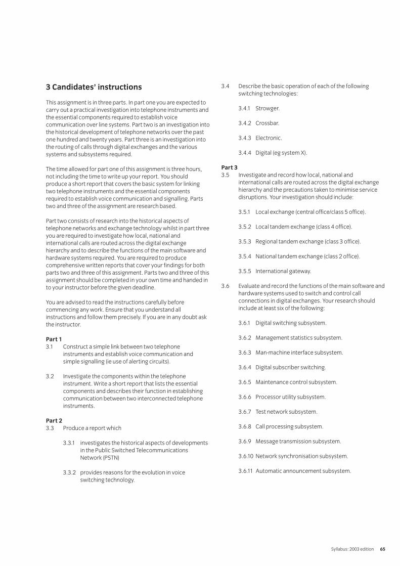
3 Candidates’ instructions
This assignment is in three parts. In part one you are expected tocarry out a practical investigation into telephone instruments andthe essential components required to establish voicecommunication over line systems. Part two is an investigation intothe historical development of telephone networks over the pastone hundred and twenty years. Part three is an investigation intothe routing of calls through digital exchanges and the varioussystems and subsystems required.
The time allowed for part one of this assignment is three hours,not including the time to write up your report. You shouldproduce a short report that covers the basic system for linkingtwo telephone instruments and the essential componentsrequired to establish voice communication and signalling. Partstwo and three of the assignment are research based.
Part two consists of research into the historical aspects oftelephone networks and exchange technology whilst in part threeyou are required to investigate how local, national andinternational calls are routed across the digital exchangehierarchy and to describe the functions of the main software andhardware systems required. You are required to producecomprehensive written reports that cover your findings for bothparts two and three of this assignment. Parts two and three of thisassignment should be completed in your own time and handed into your instructor before the given deadline.
You are advised to read the instructions carefully beforecommencing any work. Ensure that you understand allinstructions and follow them precisely. If you are in any doubt askthe instructor.
Part 13.1 Construct a simple link between two telephone
instruments and establish voice communication andsimple signalling (ie use of alerting circuits).
3.2 Investigate the components within the telephoneinstrument. Write a short report that lists the essentialcomponents and describes their function in establishingcommunication between two interconnected telephoneinstruments.
Part 23.3 Produce a report which
3.3.1 investigates the historical aspects of developmentsin the Public Switched TelecommunicationsNetwork (PSTN)
3.3.2 provides reasons for the evolution in voiceswitching technology.
3.4 Describe the basic operation of each of the followingswitching technologies:
3.4.1 Strowger.
3.4.2 Crossbar.
3.4.3 Electronic.
3.4.4 Digital (eg system X).
Part 33.5 Investigate and record how local, national and
international calls are routed across the digital exchangehierarchy and the precautions taken to minimise servicedisruptions. Your investigation should include:
3.5.1 Local exchange (central office/class 5 office).
3.5.2 Local tandem exchange (class 4 office).
3.5.3 Regional tandem exchange (class 3 office).
3.5.4 National tandem exchange (class 2 office).
3.5.5 International gateway.
3.6 Evaluate and record the functions of the main software andhardware systems used to switch and control callconnections in digital exchanges. Your research shouldinclude at least six of the following:
3.6.1 Digital switching subsystem.
3.6.2 Management statistics subsystem.
3.6.3 Man-machine interface subsystem.
3.6.4 Digital subscriber switching.
3.6.5 Maintenance control subsystem.
3.6.6 Processor utility subsystem.
3.6.7 Test network subsystem.
3.6.8 Call processing subsystem.
3.6.9 Message transmission subsystem.
3.6.10 Network synchronisation subsystem.
3.6.11 Automatic announcement subsystem.
Syllabus: 2003 edition 65
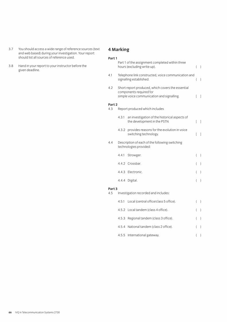
3.7 You should access a wide range of reference sources (textand web based) during your investigation. Your reportshould list all sources of reference used.
3.8 Hand in your report to your instructor before the given deadline.
4 Marking
Part 1Part 1 of the assignment completed within three hours (excluding write-up). ( )
4.1 Telephone link constructed, voice communication andsignalling established. ( )
4.2 Short report produced, which covers the essentialcomponents required for simple voice communication and signalling. [ ]
Part 24.3 Report produced which includes
4.3.1 an investigation of the historical aspects of the development in the PSTN [ ]
4.3.2 provides reasons for the evolution in voiceswitching technology. [ ]
4.4 Description of each of the following switchingtechnologies provided:
4.4.1 Strowger. ( )
4.4.2 Crossbar. ( )
4.4.3 Electronic. ( )
4.4.4 Digital. ( )
Part 34.5 Investigation recorded and includes:
4.5.1 Local (central office/class 5 office). ( )
4.5.2 Local tandem (class 4 office). ( )
4.5.3 Regional tandem (class 3 office). ( )
4.5.4 National tandem (class 2 office). ( )
4.5.5 International gateway. ( )
IVQ in Telecommunication Systems 273066
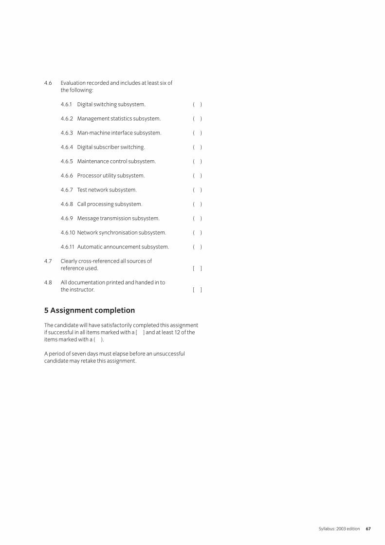
4.6 Evaluation recorded and includes at least six of the following:
4.6.1 Digital switching subsystem. ( )
4.6.2 Management statistics subsystem. ( )
4.6.3 Man-machine interface subsystem. ( )
4.6.4 Digital subscriber switching. ( )
4.6.5 Maintenance control subsystem. ( )
4.6.6 Processor utility subsystem. ( )
4.6.7 Test network subsystem. ( )
4.6.8 Call processing subsystem. ( )
4.6.9 Message transmission subsystem. ( )
4.6.10 Network synchronisation subsystem. ( )
4.6.11 Automatic announcement subsystem. ( )
4.7 Clearly cross-referenced all sources of reference used. [ ]
4.8 All documentation printed and handed in to the instructor. [ ]
5 Assignment completion
The candidate will have satisfactorily completed this assignmentif successful in all items marked with a [ ] and at least 12 of theitems marked with a ( ).
A period of seven days must elapse before an unsuccessfulcandidate may retake this assignment.
Syllabus: 2003 edition 67
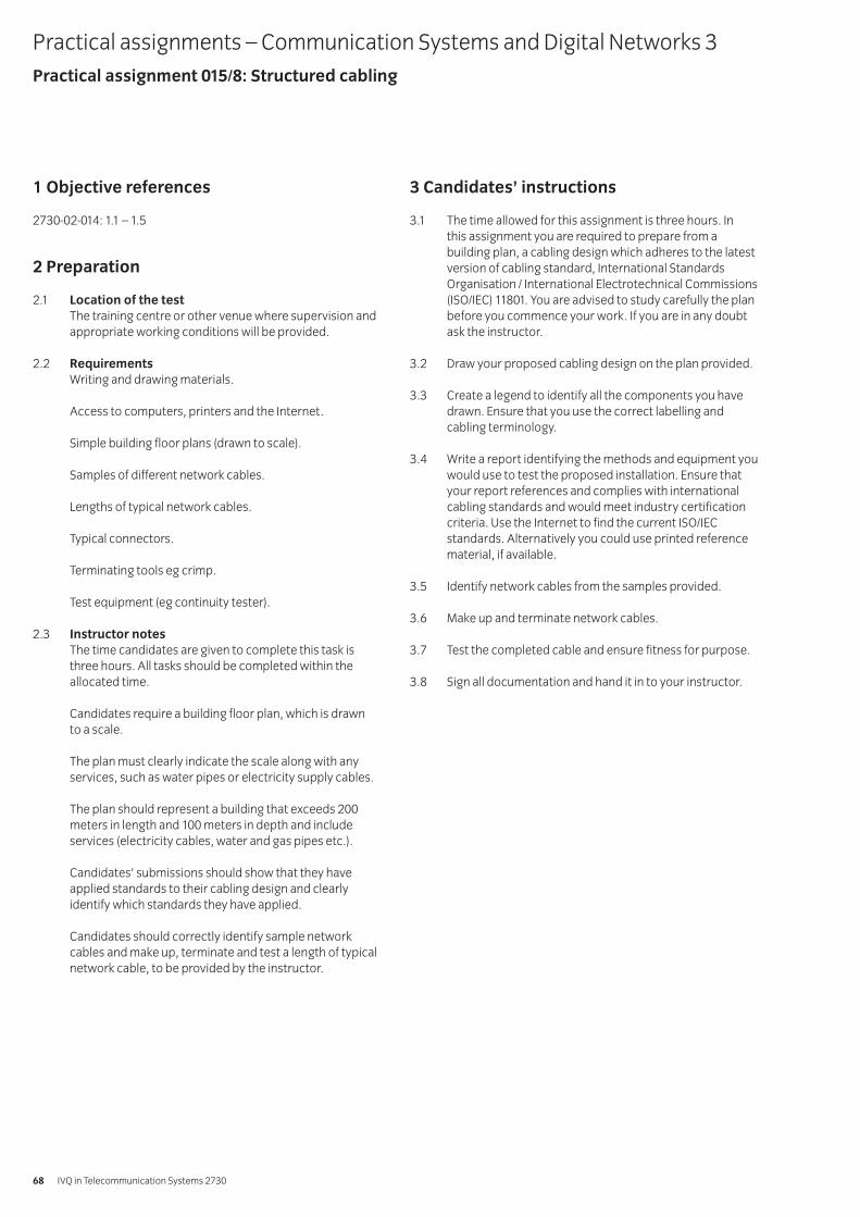
1 Objective references
2730-02-014: 1.1 – 1.5
2 Preparation
2.1 Location of the testThe training centre or other venue where supervision andappropriate working conditions will be provided.
2.2 RequirementsWriting and drawing materials.
Access to computers, printers and the Internet.
Simple building floor plans (drawn to scale).
Samples of different network cables.
Lengths of typical network cables.
Typical connectors.
Terminating tools eg crimp.
Test equipment (eg continuity tester).
2.3 Instructor notesThe time candidates are given to complete this task isthree hours. All tasks should be completed within theallocated time.
Candidates require a building floor plan, which is drawn to a scale.
The plan must clearly indicate the scale along with anyservices, such as water pipes or electricity supply cables.
The plan should represent a building that exceeds 200meters in length and 100 meters in depth and includeservices (electricity cables, water and gas pipes etc.).
Candidates’ submissions should show that they haveapplied standards to their cabling design and clearlyidentify which standards they have applied.
Candidates should correctly identify sample networkcables and make up, terminate and test a length of typicalnetwork cable, to be provided by the instructor.
3 Candidates’ instructions
3.1 The time allowed for this assignment is three hours. In this assignment you are required to prepare from abuilding plan, a cabling design which adheres to the latestversion of cabling standard, International StandardsOrganisation / International Electrotechnical Commissions(ISO/IEC) 11801. You are advised to study carefully the planbefore you commence your work. If you are in any doubtask the instructor.
3.2 Draw your proposed cabling design on the plan provided.
3.3 Create a legend to identify all the components you havedrawn. Ensure that you use the correct labelling andcabling terminology.
3.4 Write a report identifying the methods and equipment youwould use to test the proposed installation. Ensure thatyour report references and complies with internationalcabling standards and would meet industry certificationcriteria. Use the Internet to find the current ISO/IECstandards. Alternatively you could use printed referencematerial, if available.
3.5 Identify network cables from the samples provided.
3.6 Make up and terminate network cables.
3.7 Test the completed cable and ensure fitness for purpose.
3.8 Sign all documentation and hand it in to your instructor.
Practical assignments – Communication Systems and Digital Networks 3Practical assignment 015/8: Structured cabling
IVQ in Telecommunication Systems 273068
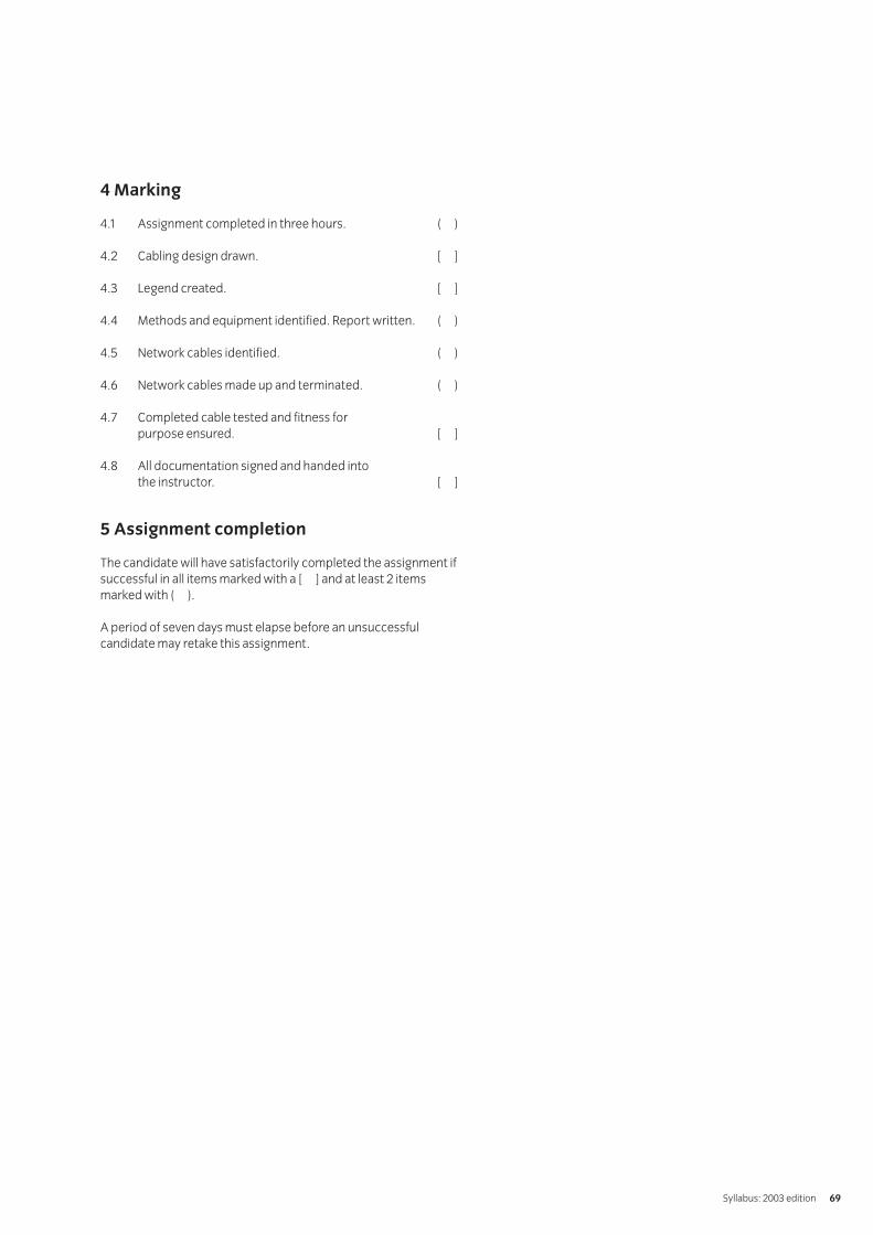
4 Marking
4.1 Assignment completed in three hours. ( )
4.2 Cabling design drawn. [ ]
4.3 Legend created. [ ]
4.4 Methods and equipment identified. Report written. ( )
4.5 Network cables identified. ( )
4.6 Network cables made up and terminated. ( )
4.7 Completed cable tested and fitness for purpose ensured. [ ]
4.8 All documentation signed and handed into the instructor. [ ]
5 Assignment completion
The candidate will have satisfactorily completed the assignment ifsuccessful in all items marked with a [ ] and at least 2 itemsmarked with ( ).
A period of seven days must elapse before an unsuccessfulcandidate may retake this assignment.
Syllabus: 2003 edition 69
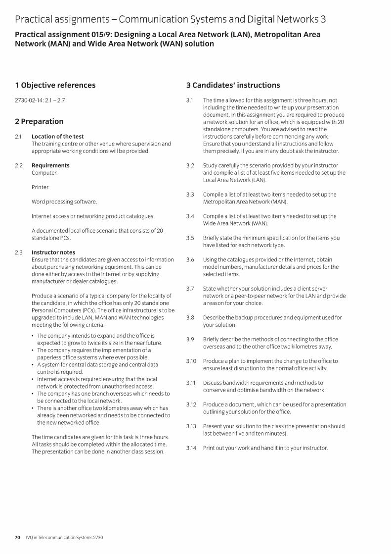
1 Objective references
2730-02-14: 2.1 – 2.7
2 Preparation
2.1 Location of the testThe training centre or other venue where supervision andappropriate working conditions will be provided.
2.2 RequirementsComputer.
Printer.
Word processing software.
Internet access or networking product catalogues.
A documented local office scenario that consists of 20standalone PCs.
2.3 Instructor notesEnsure that the candidates are given access to informationabout purchasing networking equipment. This can bedone either by access to the Internet or by supplyingmanufacturer or dealer catalogues.
Produce a scenario of a typical company for the locality ofthe candidate, in which the office has only 20 standalonePersonal Computers (PCs). The office infrastructure is to beupgraded to include LAN, MAN and WAN technologiesmeeting the following criteria:
• The company intends to expand and the office isexpected to grow to twice its size in the near future.
• The company requires the implementation of apaperless office systems where ever possible.
• A system for central data storage and central datacontrol is required.
• Internet access is required ensuring that the localnetwork is protected from unauthorised access.
• The company has one branch overseas which needs tobe connected to the local network.
• There is another office two kilometres away which hasalready been networked and needs to be connected tothe new networked office.
The time candidates are given for this task is three hours.All tasks should be completed within the allocated time.The presentation can be done in another class session.
3 Candidates’ instructions
3.1 The time allowed for this assignment is three hours, notincluding the time needed to write up your presentationdocument. In this assignment you are required to producea network solution for an office, which is equipped with 20standalone computers. You are advised to read theinstructions carefully before commencing any work.Ensure that you understand all instructions and followthem precisely. If you are in any doubt ask the instructor.
3.2 Study carefully the scenario provided by your instructorand compile a list of at least five items needed to set up theLocal Area Network (LAN).
3.3 Compile a list of at least two items needed to set up theMetropolitan Area Network (MAN).
3.4 Compile a list of at least two items needed to set up theWide Area Network (WAN).
3.5 Briefly state the minimum specification for the items youhave listed for each network type.
3.6 Using the catalogues provided or the Internet, obtainmodel numbers, manufacturer details and prices for theselected items.
3.7 State whether your solution includes a client servernetwork or a peer-to-peer network for the LAN and providea reason for your choice.
3.8 Describe the backup procedures and equipment used foryour solution.
3.9 Briefly describe the methods of connecting to the officeoverseas and to the other office two kilometres away.
3.10 Produce a plan to implement the change to the office toensure least disruption to the normal office activity.
3.11 Discuss bandwidth requirements and methods toconserve and optimise bandwidth on the network.
3.12 Produce a document, which can be used for a presentationoutlining your solution for the office.
3.13 Present your solution to the class (the presentation shouldlast between five and ten minutes).
3.14 Print out your work and hand it in to your instructor.
Practical assignments – Communication Systems and Digital Networks 3Practical assignment 015/9: Designing a Local Area Network (LAN), Metropolitan AreaNetwork (MAN) and Wide Area Network (WAN) solution
IVQ in Telecommunication Systems 273070
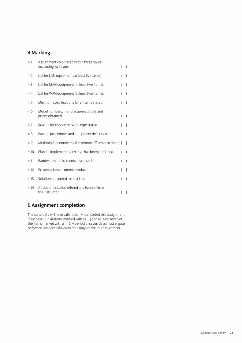
4 Marking
4.1 Assignment completed within three hours (excluding write up). ( )
4.2 List for LAN equipment (at least five items). ( )
4.3 List for MAN equipment (at least two items). ( )
4.4 List for WAN equipment (at least two items). ( )
4.5 Minimum specifications for all items stated. ( )
4.6 Model numbers, manufacturers details and prices obtained. ( )
4.7 Reason for chosen network type stated. [ ]
4.8 Backup procedures and equipment described. ( )
4.9 Methods for connecting the remote offices described. [ ]
4.10 Plan for implementing change has been produced. ( )
4.11 Bandwidth requirements discussed. ( )
4.12 Presentation document produced. [ ]
4.13 Solution presented to the class. ( )
4.14 All documentation printed and handed in to the instructor. [ ]
5 Assignment completion
The candidate will have satisfactorily completed this assignmentif successful in all items marked with a [ ] and at least seven ofthe items marked with a ( ). A period of seven days must elapsebefore an unsuccessful candidate may retake this assignment.
Syllabus: 2003 edition 71
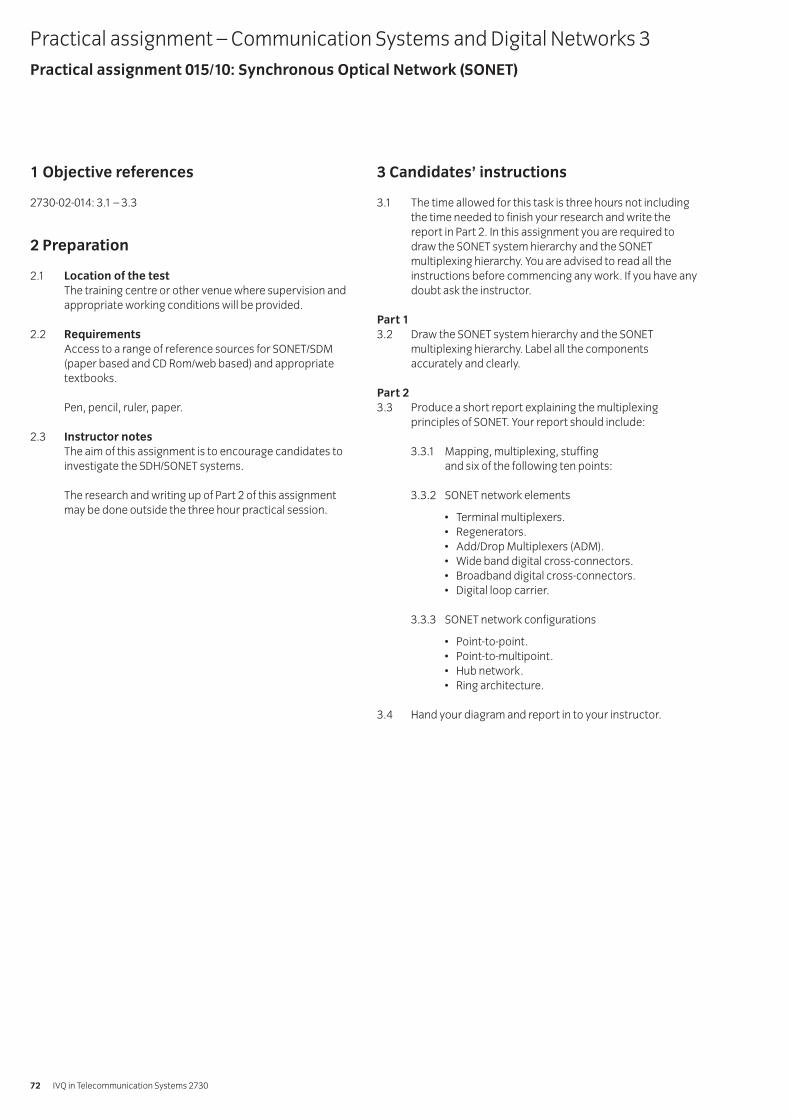
1 Objective references
2730-02-014: 3.1 – 3.3
2 Preparation
2.1 Location of the testThe training centre or other venue where supervision andappropriate working conditions will be provided.
2.2 RequirementsAccess to a range of reference sources for SONET/SDM(paper based and CD Rom/web based) and appropriatetextbooks.
Pen, pencil, ruler, paper.
2.3 Instructor notesThe aim of this assignment is to encourage candidates toinvestigate the SDH/SONET systems.
The research and writing up of Part 2 of this assignmentmay be done outside the three hour practical session.
3 Candidates’ instructions
3.1 The time allowed for this task is three hours not includingthe time needed to finish your research and write thereport in Part 2. In this assignment you are required todraw the SONET system hierarchy and the SONETmultiplexing hierarchy. You are advised to read all theinstructions before commencing any work. If you have anydoubt ask the instructor.
Part 13.2 Draw the SONET system hierarchy and the SONET
multiplexing hierarchy. Label all the componentsaccurately and clearly.
Part 23.3 Produce a short report explaining the multiplexing
principles of SONET. Your report should include:
3.3.1 Mapping, multiplexing, stuffingand six of the following ten points:
3.3.2 SONET network elements
• Terminal multiplexers.• Regenerators.• Add/Drop Multiplexers (ADM).• Wide band digital cross-connectors.• Broadband digital cross-connectors.• Digital loop carrier.
3.3.3 SONET network configurations
• Point-to-point.• Point-to-multipoint.• Hub network.• Ring architecture.
3.4 Hand your diagram and report in to your instructor.
Practical assignment – Communication Systems and Digital Networks 3Practical assignment 015/10: Synchronous Optical Network (SONET)
IVQ in Telecommunication Systems 273072
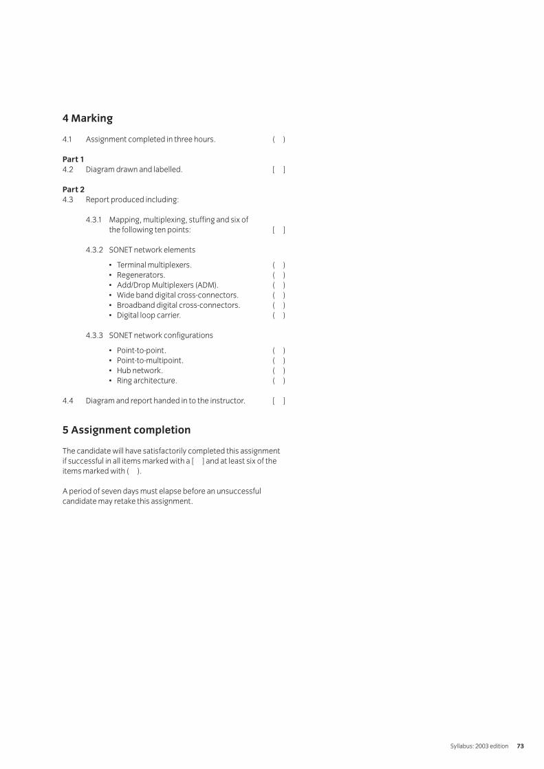
4 Marking
4.1 Assignment completed in three hours. ( )
Part 14.2 Diagram drawn and labelled. [ ]
Part 24.3 Report produced including:
4.3.1 Mapping, multiplexing, stuffing and six ofthe following ten points: [ ]
4.3.2 SONET network elements
• Terminal multiplexers. ( )• Regenerators. ( )• Add/Drop Multiplexers (ADM). ( )• Wide band digital cross-connectors. ( )• Broadband digital cross-connectors. ( )• Digital loop carrier. ( )
4.3.3 SONET network configurations
• Point-to-point. ( )• Point-to-multipoint. ( )• Hub network. ( )• Ring architecture. ( )
4.4 Diagram and report handed in to the instructor. [ ]
5 Assignment completion
The candidate will have satisfactorily completed this assignmentif successful in all items marked with a [ ] and at least six of theitems marked with ( ).
A period of seven days must elapse before an unsuccessfulcandidate may retake this assignment.
Syllabus: 2003 edition 73
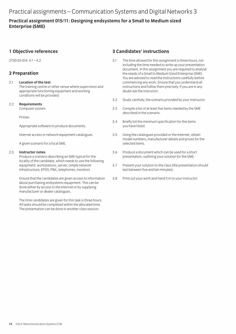
1 Objective references
2730-02-014: 4.1 – 4.2
2 Preparation
2.1 Location of the testThe training centre or other venue where supervision andappropriate functioning equipment and workingconditions will be provided.
2.2 RequirementsComputer system.
Printer.
Appropriate software to produce documents.
Internet access or network equipment catalogues.
A given scenario for a local SME.
2.3 Instructor notesProduce a scenario describing an SME typical for thelocality of the candidate, which needs to use the followingequipment: workstations, server, simple networkinfrastructure, EPOS, PBX, telephones, monitors
Ensure that the candidates are given access to informationabout purchasing endsystems equipment. This can bedone either by access to the Internet or by supplyingmanufacturer or dealer catalogues.
The time candidates are given for this task is three hours.All tasks should be completed within the allocated time.The presentation can be done in another class session.
3 Candidates’ instructions
3.1 The time allowed for this assignment is three hours, notincluding the time needed to write up your presentationdocument. In this assignment you are required to analysethe needs of a Small to Medium Sized Enterprise (SME). You are advised to read the instructions carefully beforecommencing any work. Ensure that you understand allinstructions and follow them precisely. If you are in anydoubt ask the instructor.
3.2 Study carefully, the scenario provided by your instructor.
3.3 Compile a list of at least five items needed by the SMEdescribed in the scenario.
3.4 Briefly list the minimum specification for the items you have listed.
3.5 Using the catalogues provided or the Internet, obtainmodel numbers, manufacturer details and prices for theselected items.
3.6 Produce a document which can be used for a shortpresentation, outlining your solution for the SME.
3.7 Present your solution to the class (the presentation shouldlast between five and ten minutes).
3.8 Print out your work and hand it in to your instructor.
Practical assignments – Communication Systems and Digital Networks 3Practical assignment 015/11: Designing endsystems for a Small to Medium sized Enterprise (SME)
IVQ in Telecommunication Systems 273074
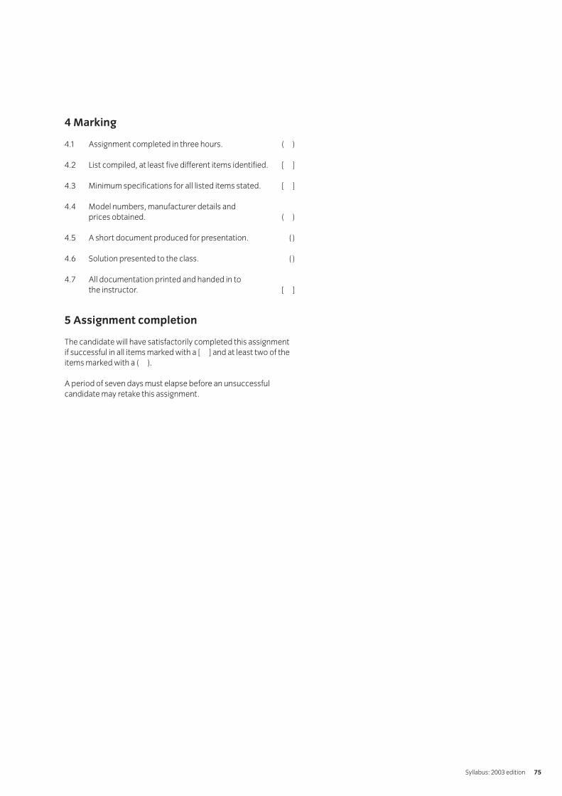
4 Marking
4.1 Assignment completed in three hours. ( )
4.2 List compiled, at least five different items identified. [ ]
4.3 Minimum specifications for all listed items stated. [ ]
4.4 Model numbers, manufacturer details and prices obtained. ( )
4.5 A short document produced for presentation. ( )
4.6 Solution presented to the class. ( )
4.7 All documentation printed and handed in to the instructor. [ ]
5 Assignment completion
The candidate will have satisfactorily completed this assignmentif successful in all items marked with a [ ] and at least two of theitems marked with a ( ).
A period of seven days must elapse before an unsuccessfulcandidate may retake this assignment.
Syllabus: 2003 edition 75
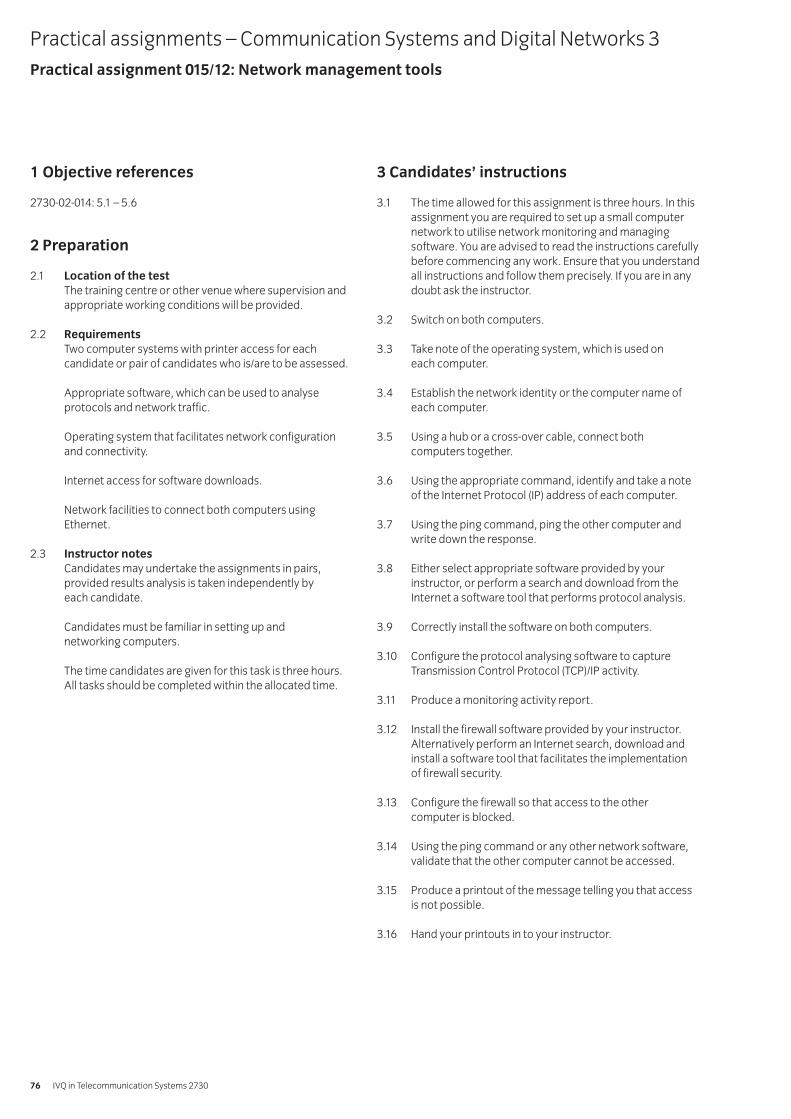
1 Objective references
2730-02-014: 5.1 – 5.6
2 Preparation
2.1 Location of the testThe training centre or other venue where supervision andappropriate working conditions will be provided.
2.2 RequirementsTwo computer systems with printer access for eachcandidate or pair of candidates who is/are to be assessed.
Appropriate software, which can be used to analyseprotocols and network traffic.
Operating system that facilitates network configurationand connectivity.
Internet access for software downloads.
Network facilities to connect both computers usingEthernet.
2.3 Instructor notesCandidates may undertake the assignments in pairs,provided results analysis is taken independently by each candidate.
Candidates must be familiar in setting up and networking computers.
The time candidates are given for this task is three hours.All tasks should be completed within the allocated time.
3 Candidates’ instructions
3.1 The time allowed for this assignment is three hours. In thisassignment you are required to set up a small computernetwork to utilise network monitoring and managingsoftware. You are advised to read the instructions carefullybefore commencing any work. Ensure that you understandall instructions and follow them precisely. If you are in anydoubt ask the instructor.
3.2 Switch on both computers.
3.3 Take note of the operating system, which is used on each computer.
3.4 Establish the network identity or the computer name ofeach computer.
3.5 Using a hub or a cross-over cable, connect both computers together.
3.6 Using the appropriate command, identify and take a noteof the Internet Protocol (IP) address of each computer.
3.7 Using the ping command, ping the other computer andwrite down the response.
3.8 Either select appropriate software provided by yourinstructor, or perform a search and download from theInternet a software tool that performs protocol analysis.
3.9 Correctly install the software on both computers.
3.10 Configure the protocol analysing software to captureTransmission Control Protocol (TCP)/IP activity.
3.11 Produce a monitoring activity report.
3.12 Install the firewall software provided by your instructor.Alternatively perform an Internet search, download andinstall a software tool that facilitates the implementation of firewall security.
3.13 Configure the firewall so that access to the other computer is blocked.
3.14 Using the ping command or any other network software,validate that the other computer cannot be accessed.
3.15 Produce a printout of the message telling you that accessis not possible.
3.16 Hand your printouts in to your instructor.
Practical assignments – Communication Systems and Digital Networks 3Practical assignment 015/12: Network management tools
IVQ in Telecommunication Systems 273076
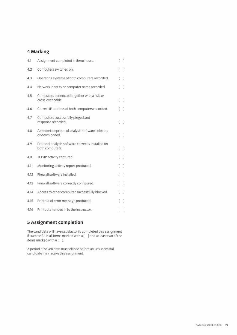
4 Marking
4.1 Assignment completed in three hours. ( )
4.2 Computers switched on. [ ]
4.3 Operating systems of both computers recorded. ( )
4.4 Network identity or computer name recorded. [ ]
4.5 Computers connected together with a hub or cross-over cable. [ ]
4.6 Correct IP address of both computers recorded. ( )
4.7 Computers successfully pinged and response recorded. [ ]
4.8 Appropriate protocol analysis software selected or downloaded. [ ]
4.9 Protocol analysis software correctly installed on both computers. [ ]
4.10 TCP/IP activity captured. [ ]
4.11 Monitoring activity report produced. [ ]
4.12 Firewall software installed. [ ]
4.13 Firewall software correctly configured. [ ]
4.14 Access to other computer successfully blocked. [ ]
4.15 Printout of error message produced. ( )
4.16 Printouts handed in to the instructor. [ ]
5 Assignment completion
The candidate will have satisfactorily completed this assignmentif successful in all items marked with a [ ] and at least two of theitems marked with a ( ).
A period of seven days must elapse before an unsuccessfulcandidate may retake this assignment.
Syllabus: 2003 edition 77
Introduction
The aim of this unit is to enable the candidate to
a describe the basic principles and concepts involved in theantenna systems used for radio communication
b describe the properties and applications of antenna systemsc appreciate the factors that effect the propagation of
radio signalsd explain the operational characteristics of radio transmitters
and receiverse describe the properties and applications of mobile
telecommunication systemsf appreciate the properties and characteristics of
satellite systems.
Notes:
1 It is suggested that about 120 guided learning hours shouldbe given to this unit.
2 It is recommended that the guided learning hours should beallocated as follows:
Fundamentals of electromagnetic radiation 7 hoursAntennas and feeder systems 12 hoursRadio Propagation 8 hoursRadio transmitters 20 hoursRadio receivers 24 hoursMobile telecommunication systems 37 hoursSatellites 9 hours
Book list
Radio Systems Technology; D.C. Green.The Essential Guide to Telecommunications; Annabel Dodd.Wireless: The Revolution in Personal Telecommunications; Ira Brodsky.
Practical competences
The candidate must be able to do the following:
1.1 Investigate the factors to be taken into account whenplanning a mobile network.
1.2 Provide a valid realistic solution to a problem involving theplanning of a mobile network.
Knowledge requirements
The instructor must ensure the candidate is able to:
Fundamentals of electromagnetic radiation1.3 Describe an electromagnetic wave in terms of its
electric and magnetic field components and direction of propagation.
1.4 Explain that the velocity of an electro-magnetic wave infree space is approximately 3 * 108 m/s.
1.5 Define wavelength; state and use the relationship betweenvelocity of propagation, frequency and wavelength.
1.6 Define wave polarisation.
1.7 Explain that the conditions for propagation of anelectromagnetic wave are satisfied by the field pattern in acapacitor energised at high frequency.
1.8 Describe how radiation from a resonant LC circuit isincreased by opening out the capacitor plates.
1.9 Explain that a straight wire provides the reactive elementsof a LC circuit.
1.10 Explain that a straight wire of length l behaves as a LCcircuit that resonates at a frequency corresponding to awavelength 2l and thus as a λ/2 dipole.
Antennas (aerials) and feeder systems1.11 Explain what is meant by the radiation pattern of
an antenna.
1.12 Define directivity and side-lobe level of an antenna.
1.13 Describe the effect on the radiation pattern of adding adirector and a reflector to a λ/2 dipole.
1.14 Explain the meaning and importance of the driving pointimpedance of a simple antenna.
1.15 Describe the increase of driving point impedance andbandwidth obtained by using a folded dipole.
1.16 Describe the effect of top capacitance of vertical aerials onthe distribution of ground and space wave energy.
1.17 Distinguish between standing-wave and travelling-waveantennas and compare their bandwidth characteristics.
1.18 Describe the construction and radiation pattern of arhombic antenna.
1.19 Describe the influence of incident wave polarisation on theperformance of simple receiving antennas.
016 Radio systems
IVQ in Telecommunication Systems 273078
1.20 Describe, from consideration of electric and magneticfields, the polarisation and radiation patterns in bothplanes of a λ/2 dipole.
1.21 Explain that radiation fields will produce electronmovement in a conductor.
1.22 Explain why a receiving antenna should be tuned to, andhave the polarisation of, the incident radiation.
1.23 Describe how a vertical λ/4 conductor earthed at its foot (aunipole) uses its image to behave as a λ/2 dipole.
1.24 Explain why a counterpoise is used when earthing is poor.
1.25 Describe simple methods of tuning a unipole.
1.26 Describe in simple terms how inverted L and T antennasimprove radiation.
1.27 Describe the reception properties of a simple loopantennas from consideration of the field components ofthe incident wave.
1.28 Describe the principle of the ferrite rod antenna used inreceivers.
1.29 Distinguish between balanced and unbalanced antennafeeders.
1.30 Describe the transmission and reception consequences ofline loss and feeder mismatch at the antenna.
1.31 Describe methods of connecting balanced andunbalanced feeders to a transmitter output circuit.
1.32 Describe a method of matching a coaxial cable to a λ/2 antenna.
1.33 Explain the limitations of coaxial feeders and open-wirelines for use with high power transmitters.
Radio propagation1.34 Explain the bandwidth requirements for telegraphy,
facsimile, Double-SideBand (DSB) telephony and Single-SideBand (SSB) telephony, high quality sound broadcastand colour television.
1.35 Describe the frequency band definitions of very lowfrequency (v.l.f.), low frequency (l.f.), medium frequency(m.f.), high frequency (h.f.), very high frequency (v.h.f.),ultra high frequency (u.h.f.), super high frequency (s.h.f.)and extra high frequency (e.h.f.) using frequency andwavelength classifications.
1.36 Describe ground wave and sky wave propagation.
1.37 Distinguish between attainable propagation ranges atfrequencies above and below 30 MHz.
1.38 Describe horizon limitation at frequencies above 30 MHz.
1.39 Calculate the approximate range of space wavepropagated signals under normal atmospheric conditionsusing the formula:dt = 4 √ htwhere: dt = distance from the transmitting antenna in km,
andht = height (in metres) of the transmitting antennaabove ground
1.40 Calculate the approximate maximum range for effectivecommunication using space wave propagated signalsunder normal atmospheric conditions using the formula:d = 4 √ ht + 4 √ hrwhere: d = total distance between the transmitting and
receiving antennae in km,ht = height (in metres) of the transmitting antennaabove ground, andhr = height (in metres) of the receiving antennaabove ground.
1.41 Describe the causes of fading in long rangecommunication.
1.42 Distinguish between ionospheric, tropospheric, space andground wave propagation.
1.43 Describe propagation ranges and bandwidth limitationsfor each mode of propagation.
1.44 Describe a typical service for each mode of propagation.
Radio transmitters1.45 Explain the need for carrier frequency stability.
1.46 List the main causes of drift in LC oscillators.
1.47 Explain that a quartz crystal can behave as a highly stableLC circuit having a resonant frequency that depends uponcrystal thickness.
1.48 Describe a simple crystal oscillator circuit.
1.49 Explain the reasons for including an r.f. amplifier stage in a transmitter.
1.50 Describe why modulation, or keying, is not carried out atthe master oscillator stage.
1.51 Sketch and describe the block diagram of a simpleContinuous Wave (CW) transmitter.
1.52 Sketch and describe the block diagram of a simple AM transmitter.
1.53 Sketch and describe the block diagram of a simple FM transmitter.
Syllabus: 2003 edition 79
1.54 Describe simple methods of connecting a transmitter to adipole or unipole antenna.
1.55 Explain the consequences of failing to match thetransmitter output stage to its load.
1.56 Derive expressions for the spectral components of a sinusoidal carrier, amplitude modulated by asinusoidal tone.
1.57 Calculate the power distribution between the spectralcomponents of the AM wave in 1.56.
1.58 Explain that, in amplitude modulation, the signalinformation is completely provided by the carrier and one sideband.
1.59 Explain how signal information may be recovered at the receiver in a Single SideBand (SSB) system.
1.60 Compare SSB. and DSB systems in terms of power and bandwidth.
1.61 Describe, by means of block diagrams, the stages of anamplitude modulated transmitter.
1.62 Describe, using simplified circuit diagrams, the typicalfrequency control, modulator, driver and output amplifierstages of an amplitude modulated transmitter.
1.63 Use block diagrams to distinguish between high-level and low-level modulation.
1.64 Sketch simplified circuits of high-level and low-levelmodulation arrangements for class B and class C radiofrequency (r.f.) output stages.
1.65 Calculate the modulator output power required foramplitude modulation of an r.f. stage to a specifiedmodulation depth and a specified efficiency of the r.f. stage.
1.66 Describe the distribution of side frequency components inthe spectrum of a sinusoidal carrier, frequency modulatedby a sinusoidal tone.
1.67 Define and apply the terms modulation index (mf),maximum deviation or rated system deviation (fmax) and deviation ratio used in frequency modulation.
1.68 Explain the effects on the frequency spectrum of an FMwave as the following parameters of the modulating toneare increased.Parameters: frequency, amplitude
1.69 Explain that a bandwidth of approximately 2(fd + fm) issufficient for satisfactory communication in an FM systemwhich has a deviation of fd and is modulated by abaseband of maximum frequency fm.
1.70 Explain why frequency-modulated services require carrierfrequencies in excess of 50 MHz.
1.71 Describe in outline the reactance modulator and ‘varactor’methods of varying oscillator frequency.
1.72 Describe in outline the indirect (Armstrong) method offrequency modulation of a carrier wave.
1.73 Explain the principle of frequency multiplication and itseffect on frequency deviation.
1.74 Describe, using block diagrams, the function of each stageof a frequency-modulated transmitter.
Radio receivers1.75 Describe the use of a parallel resonant circuit to
provide selectivity.
1.76 Describe the process of demodulating an AM wave bymeans of a diode.
1.77 Explain why the demodulating diode is ineffective if the r.f.input to it is small, and hence state the need for r.f.amplification.
1.78 Describe in simple terms how an active device (black box treatment) is used to provide r.f. amplification of areceived signal.
1.79 Describe in simple terms how an active device (black box treatment) is used to provide a.f. amplification after demodulation.
1.80 Sketch and describe the block diagram of a Tuned RadioFrequency (TRF) receiver.
1.81 Explain that when two r.f. carriers, having differentfrequencies, are present at the input of a device having asquare-law characteristic then the output signal willinclude frequency components that are the sum anddifference of those at the input.
1.82 Explain that when carrier waves having differentfrequencies are multiplied together they yield sum anddifference frequencies.
1.83 Describe the process of heterodyning as a means ofproducing an a.f. tone from two r.f. carriers.
1.84 Describe the use of heterodyning in the reception of CW.
1.85 Describe in outline the method of obtaining a fixedintermediate frequency (i.f.) in a superheterodyne receiver.
1.86 Explain the main advantage of carrying out amplification ata fixed frequency prior to demodulation.
IVQ in Telecommunication Systems 273080
1.87 Calculate, for a particular value of i.f., the local oscillatorrange to cover a specified r.f. band.
1.88 Define image frequency and adjacent channelinterference.
1.89 Explain why the level of second channel interferencedepends upon the selectivity of the input r.f. stage and thechoice of intermediate frequency.
1.90 Describe the response requirements of the r.f. amplifier ofa superheterodyne receiver.
1.91 Identify and describe the block diagram of a singlesuperheterodyne receiver which is capable of receivingCW and AM signals.
1.92 Describe, with the aid of a block diagram, a two-way radiocommunication system which employs hybridtransformers to convert from 2-wire to 4-wire working.
1.93 Explain the importance of gain and signal/noise ratio inreceiver performance.
1.94 Explain reasons for the presence of noise power at thereceiver input.
1.95 Explain that the signal/noise ratio at the receiver inputdetermines whether signal information can be identified.
1.96 Express signal power and noise power levels in dBm.
1.97 Express power gain, attenuation and signal/noise ratio in dB.
1.98 Describe the choice of intermediate frequency for m.f., h.f.and v.h.f.. single superheterodyne receivers.
1.99 Describe the i.f. bandwidth requirement for different typesof AM service.
1.100 Calculate the image frequency and explain how secondchannel interference is minimised.
1.101 Explain the principles and purpose of simple and delayedautomatic gain control.
1.102 Describe the principle of and a typical circuit for, afrequency mixer.
1.103 Describe, using block diagrams, the stages of an AMcommunication receiver.
1.104 Describe oscillator tracking error.
1.105 Describe three-point tracking with the aid of a circuitdiagram of a mixer stage.
1.106 Define sensitivity, adjacent channel selectivity, imagerejection ratio and output signal/noise ratio for asuperheterodyne receiver.
1.107 Explain the principles of operation of frequency-modulatedsuperheterodyne radio receivers.
1.108 Explain the purpose of a frequency discriminator.
1.109 Explain the consequence of non-linearity in discriminator response.
1.110 Explain, with the aid of sketches, the operation of typicalfrequency discriminator circuits.
1.111 Describe, with the aid of a block diagram, the stages of a FM receiver.
1.112 Account for the i.f. bandwidth requirement of an FM receiver.
1.113 Explain the consequences on a receiver output signal ofreducing i.f. bandwidth.
1.114 Explain what is meant by ‘capture effect’ in FM reception.
Mobile telecommunication systems1.115 Describe the basic principles and concepts involved in
mobile telecommunication systems.
1.116 Describe the properties and applications of mobiletelecommunication systems.
1.117 Investigate the range of mobile telecommunicationsystems available. Access sources of reference.
1.118 Distinguish between the differing environments of privateand public mobile telecommunications systems in terms oftheir applications and user groups.
1.119 Explain why there was a major shift in the 1990s towardsgreater standardisation in mobile telecommunication.
1.120 State the frequency bands designated for use in Private Mobile Radio (PMR) and Public Land MobileNetwork (PLMN) systems and give reasons why thesebands are used.
1.121 With the aid of a diagram, show that in a cellular radiosystem the coverage area is divided into a number of linkedcells, each with a base station.
1.122 Describe the concept of frequency re-use in cellular systems.
1.123 Explain that in conventional Frequency Division Duplex(FDD) systems, separate frequency bands are used for theuplink and downlink transmissions.
Syllabus: 2003 edition 81
1.124 State the advantages associated with the use of digital rather than analogue signal processing techniques in telecommunications.
1.125 Describe the use of Time Division Multiple Access (TDMA)in modern mobile telecommunications systems.
1.126 Describe the problems associated with multiple pathpropagation in mobile telecommunications systems anddescribe the techniques used to combat those effects.
1.127 Explain why there is a need for error protection over the mobile air interface and state typical examples ofschemes used.
1.128 Explain why there is a requirement for encryption over theair interface in mobile telecommunication systems.
1.129 Explain that PMR systems can be designed to provide local, regional or national coverage, depending on their application.
1.130 State that Terrestrial Trunked Radio (TETRA), is the firstdigital standard for PMR and Public Access Mobile Radio(PAMR) systems, developed by the EuropeanTelecommunications Standards Institute (ETSI).
1.131 Describe the basic TETRA system components, interfacesand operation.
1.132 Explain why the Global System for Mobiletelecommunications (GSM) is the most popular standard inthe world for second Generation (2G) PLMN systems.
1.133 Draw the block diagram of a generic PLMN identifying the following components and their main functionality:Mobile Station (MS), Base Transceiver Station (BTS), BaseStation Controller (BSC), Mobile Switching Centre (MSC),Home Location Register (HLR), Visitor Location Register(VLR), Authentication Centre (AUC), Equipment IdentityRegister (EIR).
1.134 Describe the concept of ‘mobility management’ in a PLMN.
1.135 Explain that a cellular telephone regularly identifies itself to the nearest base station, whether or not a call is in progress.
1.136 State the possible reasons for a handover taking place in a PLMN.
1.137 Describe the main factors that determine cell size in a PLMN.
1.138 Describe how cell splitting and/or sectorisation canincrease cell capacity.
1.139 State the inherent limitations of second generation PLMNdata services.
1.140 Explain why packet switching techniques are moreefficient than circuit switching for most mobile data applications.
1.141 Describe how time slot combination schemes such as theGeneral Packet Radio Service (GPRS), can be used toprovide higher data rates to users in TDMA systems.
1.142 Describe Enhanced Data rates for GSM Evolution (EDGE), asa modification to the GSM air interface modulation schemein order to facilitate higher data rates.
1.143 State the implications for the introduction of EDGE intoexisting GSM networks.
1.144 Describe the Third Generation (3G) standardisationprocess and the main organisations involved.
1.145 State the proposed 3G air interfaces and the implicationsfor global roaming.
Satellites1.146 Describe the range of useful applications for satellites.
Applications: communications (point-to-point, militaryand mobile), data communication,meteorological/weather, geophysical survey, surveillance(spy), navigational aids, television (and radio) broadcasting
1.147 Describe the classes of orbits used by satellites and their characteristics.Orbits: elliptical, low earth, polar circular, geostationary.
1.148 Explain the advantages and disadvantages of thegeostationary orbit.Advantages: always in view (one satellite is able tocommunicate with 42% of the earth’s surface), threesatellites are able to cover the entire globe (excepting the polar regions), there is no need for complicatedtracking systems as the satellite remains virtually fixedabove a given point on the equator, there are no breaks in transmission.Disadvantages: the received signal strength is very weak(because of the large distances involved), propagationdelay is considerable, more complex launch vehiclesrequired, affected by earth and lunar eclipses, no coverageof the polar regions
1.149 State the distance in km above the equator for a satellite ina geostationary orbit.
1.150 Describe how satellites are placed into a geostationaryorbit discuss the range of launch vehicles available.
1.151 Calculate the minimum propagation delay forcommunication with a geostationary satellite.
1.152 Describe the sources of noise which are likely to effectcommunication via a satellite in a geostationary orbit.
IVQ in Telecommunication Systems 273082

1.153 Explain what is meant by the term frequency re-use andhow it may be achieved for satellite communications.
1.154 Describe the range of equipment on board a satellite in ageostationary orbit.
1.155 Explain how the communications facilities may be accessed.
1.156 Explain how severe weather conditions are likely to affectcommunications links via geostationary satellites.
Syllabus: 2003 edition 83
Test specification for written paperRadio Systems (2730-02-016)
This is a written examination paper lasting three hours with tenquestions. Candidates must answer all questions.
The examination paper will cover the knowledge specifications:
Approximate %examination
Topic weighting
Fundamentals of electromagnetic radiation 5
Antennas and feeder systems 14
Radio propagation 8
Radio transmitters 20
Radio receivers 25
Mobile telecommunication systems 20
Satellites 8
Assessment
IVQ in Telecommunication Systems 273084
1 Objective references
2730-02-016: 1.1 and 1.2
2 Preparation
2.1 Location of the testThe training centre or other venue where supervision andappropriate working conditions will be provided.
2.2 RequirementsWriting and drawing materials.
Copy of section 6 (scenario).
2.3 Instructor NotesThe aim of this assignment is to test the candidate’sknowledge and understanding of cellular planningprinciples and the propagation characteristics of radiowaves in the ultra high frequency (u.h.f.) band.
The time allowed for this assignment is three hours, notincluding the time needed to write up the report.
Instructors are encouraged to adapt the scenario insection 6.1, in order to make it relevant to their own region.Maps of the region would enhance the originality of theassignment and produce a more realistic response fromthe candidates. If this option is taken the candidate’sinstructions will need to be adapted.
3 Candidates’ instructions
3.1 The time allowed for this assignment is three hours, notincluding the time needed to write up your report. Studycarefully the scenario which you have been given by yourinstructor. Ensure that you understand all therequirements of the assignment and follow them precisely.If you are in any doubt ask your instructor.
3.2 Your task is to plan a Global System for MobileCommunication (GSM) network, to provide optimum GSMcoverage in the cities of Northbank and Southbank,identified on the map. Your detailed plan should include:
3.2.1 The number of cells required to meet coverage requirements.
3.2.2 When determining 3.2.1, consideration must begiven to the geography, population density,business concentration, frequency re-use (includingcluster size and re-use distance) and allowance ofcontrol channels.
3.3.3 Indicate your chosen transmission plan to link thecells to the Base Station Controllers (BSCs) andMobile Switching Centres (MSCs), and your chosentransmission medium (taking into account thegeography, particularly the river and other majortransport routes). The Public SwitchedTelecommunications Network (PSTN) and associatedtransmission architecture is located in Southbank.
3.2.4 The locations and optimum number of the BSCs and MSCs.
3.2.5 Approximate height of the BSC antenna (useradio/radar range equation to estimate height).
3.2.6 A diagram should be used to clearly illustrate yournetwork architecture.
3.2.7 Hand in the plan to your instructor.
Practical assignments – Radio Systems PracticePractical assignment 017/1: Planning a Global System for Mobile Communication (GSM) network
Syllabus: 2003 edition 85
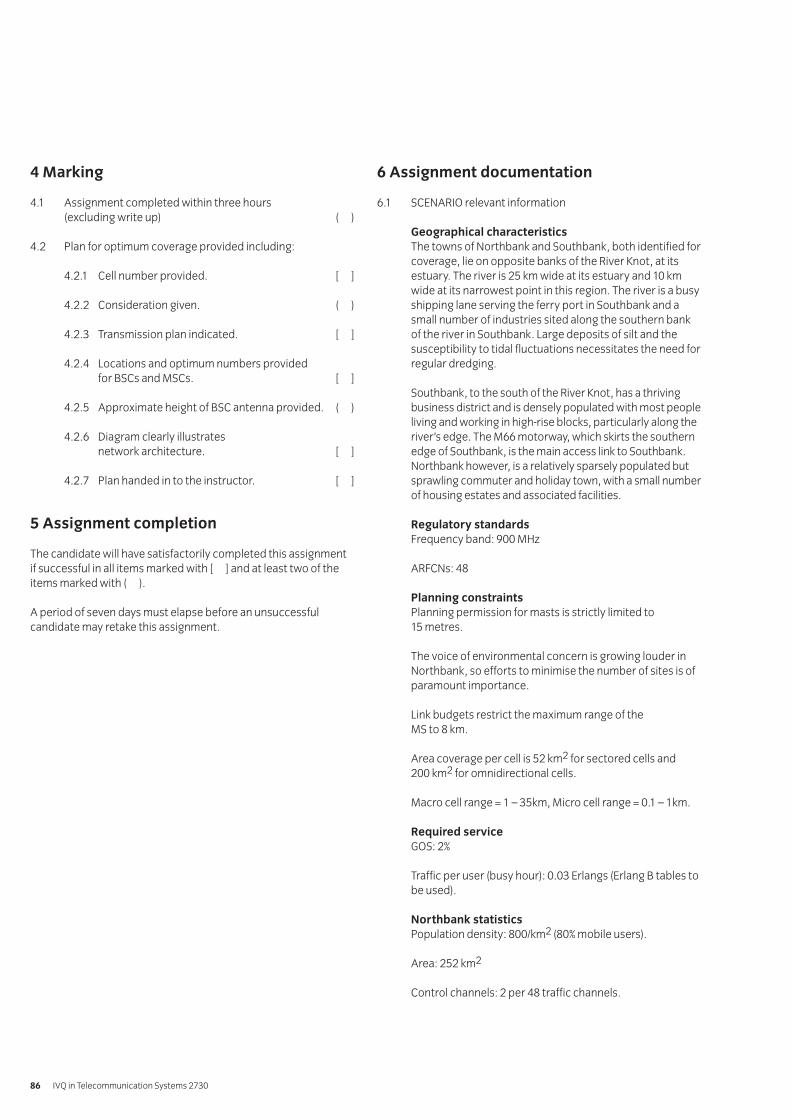
4 Marking
4.1 Assignment completed within three hours (excluding write up) ( )
4.2 Plan for optimum coverage provided including:
4.2.1 Cell number provided. [ ]
4.2.2 Consideration given. ( )
4.2.3 Transmission plan indicated. [ ]
4.2.4 Locations and optimum numbers provided for BSCs and MSCs. [ ]
4.2.5 Approximate height of BSC antenna provided. ( )
4.2.6 Diagram clearly illustrates network architecture. [ ]
4.2.7 Plan handed in to the instructor. [ ]
5 Assignment completion
The candidate will have satisfactorily completed this assignmentif successful in all items marked with [ ] and at least two of theitems marked with ( ).
A period of seven days must elapse before an unsuccessfulcandidate may retake this assignment.
6 Assignment documentation
6.1 SCENARIO relevant information
Geographical characteristicsThe towns of Northbank and Southbank, both identified forcoverage, lie on opposite banks of the River Knot, at itsestuary. The river is 25 km wide at its estuary and 10 kmwide at its narrowest point in this region. The river is a busyshipping lane serving the ferry port in Southbank and asmall number of industries sited along the southern bankof the river in Southbank. Large deposits of silt and thesusceptibility to tidal fluctuations necessitates the need forregular dredging.
Southbank, to the south of the River Knot, has a thrivingbusiness district and is densely populated with most peopleliving and working in high-rise blocks, particularly along theriver’s edge. The M66 motorway, which skirts the southernedge of Southbank, is the main access link to Southbank.Northbank however, is a relatively sparsely populated butsprawling commuter and holiday town, with a small numberof housing estates and associated facilities.
Regulatory standardsFrequency band: 900 MHz
ARFCNs: 48
Planning constraintsPlanning permission for masts is strictly limited to 15 metres.
The voice of environmental concern is growing louder inNorthbank, so efforts to minimise the number of sites is ofparamount importance.
Link budgets restrict the maximum range of the MS to 8 km.
Area coverage per cell is 52 km2 for sectored cells and 200 km2 for omnidirectional cells.
Macro cell range = 1 – 35km, Micro cell range = 0.1 – 1km.
Required serviceGOS: 2%
Traffic per user (busy hour): 0.03 Erlangs (Erlang B tables tobe used).
Northbank statisticsPopulation density: 800/km2 (80% mobile users).
Area: 252 km2
Control channels: 2 per 48 traffic channels.
IVQ in Telecommunication Systems 273086
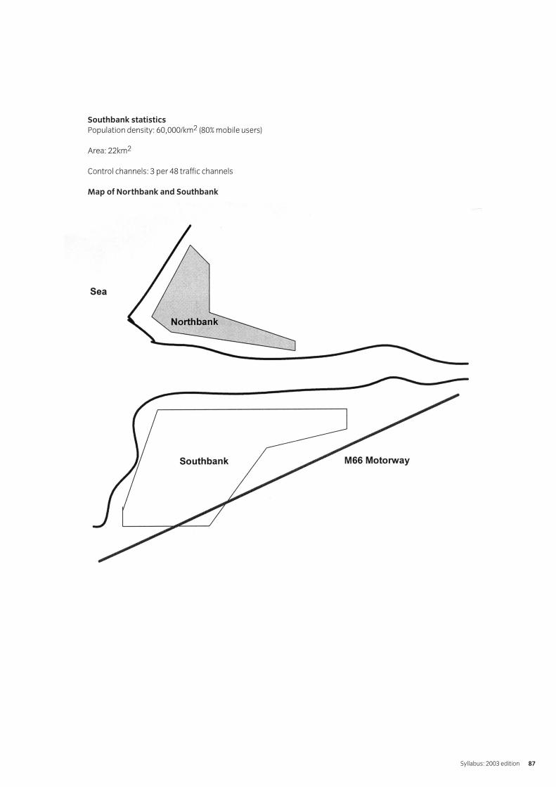
Southbank statisticsPopulation density: 60,000/km2 (80% mobile users)
Area: 22km2
Control channels: 3 per 48 traffic channels
Map of Northbank and Southbank
Syllabus: 2003 edition 87
Introduction
The aim of this unit is to enable the candidate to understand the
a general concepts of programming languagesb structures used within computer programsc information needed by programmers to produce
software solutions.
Notes:
1 It is suggested that about 120 guided learning hours shouldbe given to this unit.
2 It is recommended that the guided learning hours should beallocated as follows:
Basic knowledge 36 hoursBasic programming concepts 78 hours
Book list
The Formal Semantics of Programming Languages; Glynn Winskel.The Structure of Typed Programming Languages; David A. Schmidt.
Practical competences
The candidate must be able to do the following:
1.1 Create a programme using pseudocode for given task.
1.2 Produce a flowchart and top down design for a given process.
1.3 Research and report on the chronological development ofcomputer processor programming.
1.4 Identify reference sources of information.
Knowledge requirements
The instructor must ensure the candidate is able to:
Basic knowledge1.5 Describe the main computer components crucial to
program execution.Components: disk storage, Random Access Memory (RAM), Central Processing Unit (CPU),Input/Output (I/O) devices
1.6 Describe the procedures involved for programs to beloaded, executed and discarded.
1.7 Describe the basic logical structures of a computer.
1.8 Discuss data handling by the CPU and the role of softwareto deal with data entities.
1.9 Explain the differences between machine code, low-levellanguages and high-level languages.
1.10 Give examples of machine code instructions.Examples: peek, poke
1.11 Compare and contrast low-level languages.Low-level languages: assembly language, machine code
1.12 Identify examples of code for a given low-level language.
1.13 Analyse program code for a small program and explain thecommand lines and their function.
1.14 List a number of high-level languages.High-level languages: interpreted languages, basic
1.15 Identify examples of coding for a high-level language.
1.16 Obtain and analyse a program code for a high-level language.
1.17 Explain the importance that commenting plays in theprogramming process.
1.18 Explain the differences between compilers andinterpreters.
Basic programming concepts1.19 Identify data types, values and their representation.
Types: integers, real numbers (floating-pointrepresentation), character strings, Boolean operators
1.20 Describe how programming achieves basic arithmetic,logical and relational operations.
1.21 Describe basic program structures.Structures: declaration, execution and termination
1.22 Explain basic program controls.Controls: sequences, selections, repetitions
1.23 Describe the concepts and usage of subprograms.Subprograms: functions, subroutines
1.24 Identify basic program design components.Components: aims, programming methods,development stages, documentation
1.25 List the components of a program specification.Components: reliability, maintainability, portability,readability, re-usability, efficiency, development time and costs
1.26 Explain detailed specifications.Specifications: input, output, performance, security
018 Programming Principles
IVQ in Telecommunication Systems 273088
1.27 Define the function and use of algorithms.
1.28 Draw a flowchart for a given process showing process boxes,decision boxes, input/output boxes, using a simple routine.Routine: keyboard operation
1.29 Describe a top down design for a given process.
1.30 Discuss the differences, advantages and disadvantages offlowcharts and top down designs.
1.31 Describe the basic concepts of procedure programming.
1.32 Describe the basic concepts of object-orientedprogramming.
1.33 Explain a class.Class: structure and behaviour of similar objects
1.34 Explain an object and its relation to class.
1.35 Describe the function of an object.
1.36 Explain objects and inheritance.
1.37 State the purpose of object encapsulation.
1.38 Describe the benefits of Object Orientated Programming(OOP) in relation to the usage of subprograms.
1.39 List programming languages and identify their levels.
1.40 Describe a low-level language in detail. Low-level language: machine code, assembly
1.41 Describe a high-level language in detail.High-level language: C, basic, VB, Java, Pascal, Cobol
1.42 Briefly explain databases, query languages and fourthGeneration Languages (4GL).
1.43 Explain database definition types and their application.
1.44 Define Standard Query Language (SQL) and 4GL and theirrelations to relational database systems.
1.45 Identify display formats and explain the difference betweendisplay coding (tagging) and computer languages.Coding: Standard Generalized Markup Language (SGML),Hyper Text Markup Language (HTML), Extensible MarkupLanguage (XML)
1.46 Produce coding for a simple HTML Web page using a plain text editor ie without the use of software, whichoutputs as HTML.
Syllabus: 2003 edition 89
Test specification for written paperProgramming Principles (2730-02-018)
This is a written examination paper lasting three hours with tenquestions. Candidates must answer all questions.
The examination paper will cover the knowledge specifications:
Approximate %examination
Topic weighting
01 Basic knowledge 30
02 Basic programming concepts 70
Assessment
IVQ in Telecommunication Systems 273090
1 Objective references
2730-02-018: 1.1 – 1.4
2 Preparation
2.1 Location of the testThe training centre or other venue where supervision andappropriate working conditions will be provided.
2.2 RequirementsWriting and drawing materials.
Access to reference materials.
2.3 Instructor notes
Part 1 and 2The aim of part one and part two of this assignment is todemonstrate an ability to use pseudocode.
The time candidates are given for this task is three hours.All tasks should be completed within the allocated time.
Part 3The aim of part three of this assignment is to demonstratethe ability to research and report findings on thechronological development of computer processorprogramming.
The time candidates are given for this task in is three hours.The students will need to spend a considerable amount oftheir own time in researching part three of the assignment.
3 Candidates’ instructions
3.1 The time allowed for parts one and two of this assignmentis three hours. You are required to create pseudocode for asimple task and draw a flowchart showing the pseudocodeprocedure. You are advised to read the instructionscarefully before commencing any work. Ensure that youunderstand all instructions and follow them precisely. Ifyou are in any doubt ask the instructor.
The time allowed for part three of this assignment is threehours. You are required to research and create a reportthat relates to the chronological development of computerprocessor programming. The report for part three shouldbe completed in your own time and handed in to yourinstructor before the given headline.
Part 13.2 Write a simple program using pseudocode. The
program should
3.2.1 welcome the user, inform them of the task andinstruct them how to proceed.
3.2.2 request three numbers from the user.The first two numbers will become operands whichwill be added together.The third number will represent their answer to theaddition of the first two numbers.
3.2.3 If the answer is correct, the user should receive agreeting message read as ‘Congratulation, you hadthe correct answer! Well done!’.
3.2.4 If the answer is incorrect, the user should receive a message ‘Sorry, the answer was wrong. Please try again’.
Part 23.3 Draw a flow chart of the program using the following
representations:
3.3.1 Output (‘ABC’) to display three characters ABC onthe computer monitor.
3.3.2 Input (a) to get a number from the keyboard andstore that number in a variable.
3.3.3 Use // to signify a comment line inside the program.
Practical assignments – Programming Principals PracticePractical assignment 019/1: Using pseudocode
Syllabus: 2003 edition 91
Part 33.4 Research and produce a report that relates to the
chronological development of computer processorprogramming. The report should identify
3.4.1 at least five major advancements in the area ofcomputer programming and their significance
3.4.2 the individuals or companies responsible forinitiating and developing the advancements in 3.4.1
3.4.3 the source of the reference material used tocompile the report.
3.5 Hand your pseudocode programme, drawing and report into your instructor.
4 Marking
4.1 All three parts of the assignment completed in the given time. ( )
Part 14.2 Pseudocode written including:
4.2.1 Welcoming the user, informing them of the task and instructing them how to proceed. [ ]
4.2.2 Requesting three numbers from the user. [ ]
4.2.3 If the answer is correct, the user receives theappropriate greeting message. [ ]
4.2.4 If the answer is incorrect, the user receives theappropriate greeting message. [ ]
Part 24.3 Flowchart drawn using the following representations:
4.3.1 Output (‘ABC’) displays three characters ABC on the computer monitor. ( )
4.3.2 Number input (a) from the keyboard and stored in a variable. ( )
4.3.3 // used to signify a comment line inside the program. ( )
Part 34.4 Research carried out and report produced, which identifies
4.4.1 five major advancements and their significance [ ]
4.4.2 those responsible for initiation and development of 3.4.1 [ ]
4.4.3 the source of reference material. ( )
4.5 Pseudocode, drawing and report handed in to the instructor. [ ]
5 Assignment completion
The candidate will have satisfactorily completed this assignmentif successful in all items marked with a [ ] and at least two of theitems marked with a ( ).
A period of seven days must elapse before an unsuccessfulcandidate may retake this assignment.
IVQ in Telecommunication Systems 273092
Introduction
The aim of this unit is to enable the candidate to
a advance and broaden the understanding of mathematicsb acquire additional mathematical knowledge (not mandatory)
for application to the Diploma option units in the topic areasof radio systems and programming
c gain sufficient mathematical knowledge to proceed to thefirst year of a telecommunications or related degree courseafter successful completion of the Diploma.
Notes:
1 The subjects in this unit would benefit if an integrativeapproach is used.
2 Where possible, it is expected that worked examples will beselected to represent telecommunications, radio systemsand programming problems.
3 It is suggested that about 60 guided learning hours should begiven to this unit.
Book list
Engineering Mathematics; L. Mustoe.
Knowledge requirements
The instructor must ensure the candidate is able to:
Quadratic functions1.1 Factorise quadratic expressions, including perfect squares
and the difference of two squares.
1.2 Solve quadratic equations with real roots by factorisationand by quadratic formula.
1.3 Determine a quadratic equation from its two roots.
1.4 Apply quadratic equations to practical problems such as linearly accelerated motion and second order chemical reactions.
Linear law fitting1.5 Identify dependent and independent variables.
1.6 State the relation between two variables which are
i) directly proportional
ii) inversely proportional.
1.7 Calculate the proportionality constant from given data.
1.8 State that, for inverse proportion, the product of variables is constant.
1.9 Solve problems involving the laws of Hooke, Boyle, Charles and Ohm (I α V and I α 1/R) and determine theproportionality constants.
1.10 Identify coordinates from a set of experimental data whichobeys a linear law, eg Hooke’s law.
1.11 Draw the best fit straight line by eye to fit the points.
1.12 Determine the gradient of the straight line and state itsphysical meaning.
1.13 Deduce the equation of the straight line using the gradientand the intercept.
1.14 Determine the law of the straight line graph from thecoordinates of two points on the line.
1.15 Use the equation to calculate other values of thedependent variable.
Binomial expansion1.16 Expand (a + b)2 and (a + b)3
1.17 Expand the general binomial expression(a + b)n
for positive integral n.
1.18 Identify the general form and signs of the binomialexpansion terms, with their numerical coefficients(Pascal’s triangle).
1.19 Expand expressions of the form (1 + x)n for positive integral n.
Graphs1.20 Plot the graphs of
y = e±ax
with the aid of a calculator.
1.21 Relate the graphsy of aebx and a(1 – e–bx),where a and b are positive, to communications technology applications.
1.22 Use log-linear graph paper to plot straight line graphs fory = e±x and aebx
1.23 Determine whether experimental results are related bylaws of the typey = aebx and y = axn
and estimate the constants from log-linear and log-log graphs.
1.24 Define the gradient of any curve at a point as the gradientof the tangent at that point.
020 Advanced Mathematics 1
Syllabus: 2003 edition 93
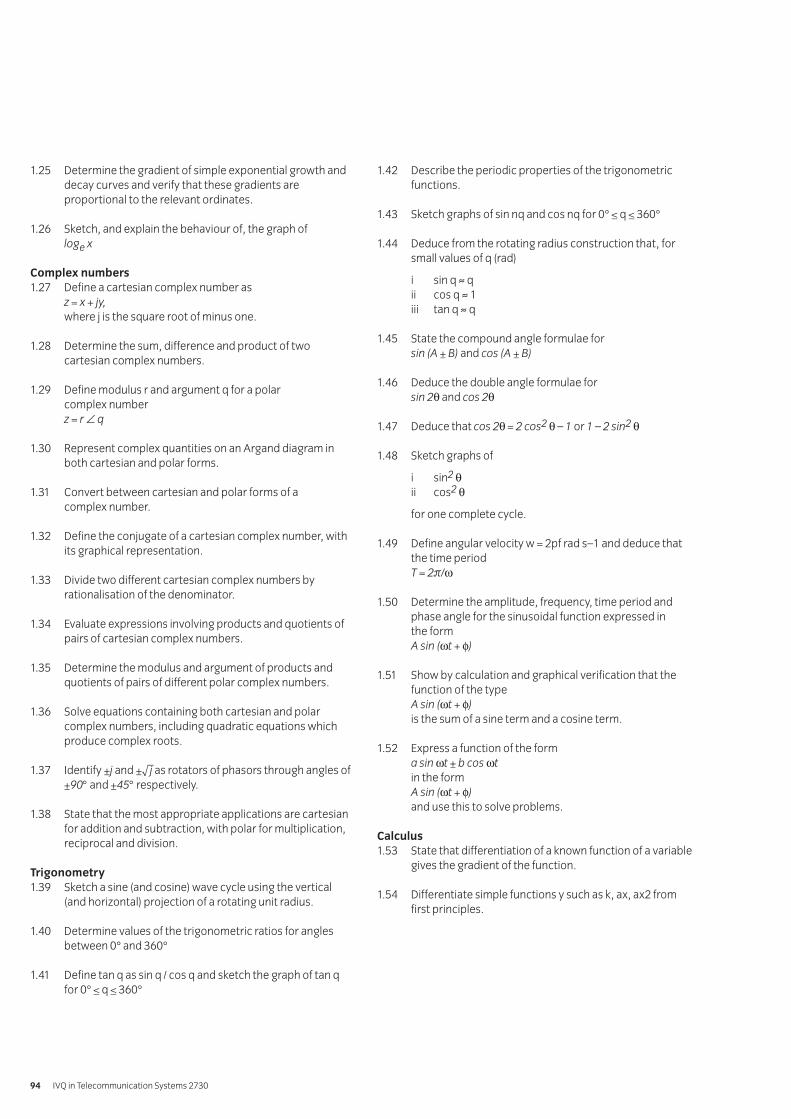
1.25 Determine the gradient of simple exponential growth anddecay curves and verify that these gradients areproportional to the relevant ordinates.
1.26 Sketch, and explain the behaviour of, the graph ofloge x
Complex numbers1.27 Define a cartesian complex number as
z = x + jy,where j is the square root of minus one.
1.28 Determine the sum, difference and product of twocartesian complex numbers.
1.29 Define modulus r and argument q for a polar complex numberz = r ∠ q
1.30 Represent complex quantities on an Argand diagram inboth cartesian and polar forms.
1.31 Convert between cartesian and polar forms of a complex number.
1.32 Define the conjugate of a cartesian complex number, withits graphical representation.
1.33 Divide two different cartesian complex numbers byrationalisation of the denominator.
1.34 Evaluate expressions involving products and quotients ofpairs of cartesian complex numbers.
1.35 Determine the modulus and argument of products andquotients of pairs of different polar complex numbers.
1.36 Solve equations containing both cartesian and polarcomplex numbers, including quadratic equations whichproduce complex roots.
1.37 Identify ±j and ±√–j as rotators of phasors through angles of±90° and ±45° respectively.
1.38 State that the most appropriate applications are cartesianfor addition and subtraction, with polar for multiplication,reciprocal and division.
Trigonometry1.39 Sketch a sine (and cosine) wave cycle using the vertical
(and horizontal) projection of a rotating unit radius.
1.40 Determine values of the trigonometric ratios for anglesbetween 0° and 360°
1.41 Define tan q as sin q / cos q and sketch the graph of tan qfor 0° ≤ q ≤ 360°
1.42 Describe the periodic properties of the trigonometricfunctions.
1.43 Sketch graphs of sin nq and cos nq for 0° ≤ q ≤ 360°
1.44 Deduce from the rotating radius construction that, forsmall values of q (rad)
i sin q ≈ qii cos q ≈ 1iii tan q ≈ q
1.45 State the compound angle formulae forsin (A ± B) and cos (A ± B)
1.46 Deduce the double angle formulae forsin 2θ and cos 2θ
1.47 Deduce that cos 2θ = 2 cos2 θ – 1 or 1 – 2 sin2 θ
1.48 Sketch graphs of
i sin2 θii cos2 θ
for one complete cycle.
1.49 Define angular velocity w = 2pf rad s–1 and deduce that the time periodT = 2π/ω
1.50 Determine the amplitude, frequency, time period andphase angle for the sinusoidal function expressed in the formA sin (ωt + φ)
1.51 Show by calculation and graphical verification that thefunction of the typeA sin (ωt + φ)is the sum of a sine term and a cosine term.
1.52 Express a function of the forma sin ωt ± b cos ωtin the formA sin (ωt + φ)and use this to solve problems.
Calculus1.53 State that differentiation of a known function of a variable
gives the gradient of the function.
1.54 Differentiate simple functions y such as k, ax, ax2 from first principles.
IVQ in Telecommunication Systems 273094
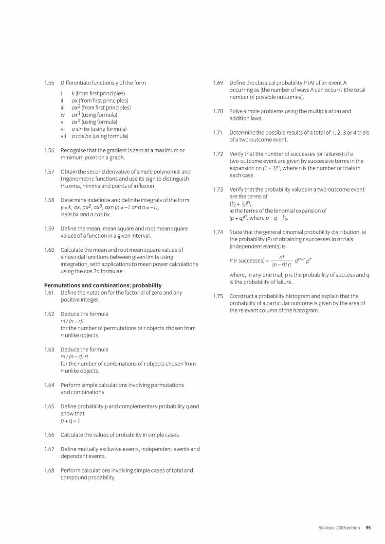
1.55 Differentiate functions y of the form
i k (from first principles)ii ax (from first principles)iii ax2 (from first principles)iv ax3 (using formula)v axn (using formula)vi a sin bx (using formula)vii a cos bx (using formula)
1.56 Recognise that the gradient is zero at a maximum orminimum point on a graph.
1.57 Obtain the second derivative of simple polynomial andtrigonometric functions and use its sign to distinguishmaxima, minima and points of inflexion.
1.58 Determine indefinite and definite integrals of the formy = k, ax, ax2, ax3, axn (n ≠ –1 and n = –1),a sin bx and a cos bx
1.59 Define the mean, mean square and root mean squarevalues of a function in a given interval.
1.60 Calculate the mean and root mean square values ofsinusoidal functions between given limits usingintegration, with applications to mean power calculationsusing the cos 2q formulae.
Permutations and combinations; probability1.61 Define the notation for the factorial of zero and any
positive integer.
1.62 Deduce the formulan! / (n – r)!for the number of permutations of r objects chosen from n unlike objects.
1.63 Deduce the formulan! / (n – r)! r!for the number of combinations of r objects chosen from n unlike objects.
1.64 Perform simple calculations involving permutations and combinations.
1.65 Define probability p and complementary probability q andshow thatp + q = 1
1.66 Calculate the values of probability in simple cases.
1.67 Define mutually exclusive events, independent events anddependent events.
1.68 Perform calculations involving simple cases of total andcompound probability.
1.69 Define the classical probability P (A) of an event Aoccurring as (the number of ways A can occur) / (the totalnumber of possible outcomes).
1.70 Solve simple problems using the multiplication andaddition laws.
1.71 Determine the possible results of a total of 1, 2, 3 or 4 trialsof a two-outcome event.
1.72 Verify that the number of successes (or failures) of a two-outcome event are given by successive terms in theexpansion on (1 + 1)n, where n is the number or trials ineach case.
1.73 Verify that the probability values in a two-outcome eventare the terms of(1⁄2 + 1⁄2)n,ie the terms of the binomial expansion of(p + q)n, where p = q = 1⁄2.
1.74 State that the general binomial probability distribution, iethe probability (P) of obtaining r successes in n trials(independent events) is
P (r successes) = qn–r pr
where, in any one trial, p is the probability of success and qis the probability of failure.
1.75 Construct a probability histogram and explain that theprobability of a particular outcome is given by the area ofthe relevant column of the histogram.
n!(n – r)! r!
Syllabus: 2003 edition 95
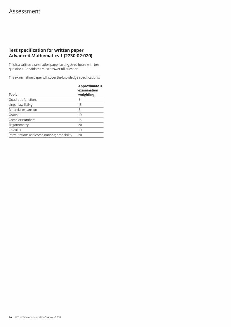
Test specification for written paperAdvanced Mathematics 1 (2730-02-020)
This is a written examination paper lasting three hours with tenquestions. Candidates must answer all question.
The examination paper will cover the knowledge specifications:
Approximate %examination
Topic weighting
Quadratic functions 5
Linear law fitting 15
Binomial expansion 5
Graphs 10
Complex numbers 15
Trigonometry 20
Calculus 10
Permutations and combinations; probability 20
Assessment
IVQ in Telecommunication Systems 273096
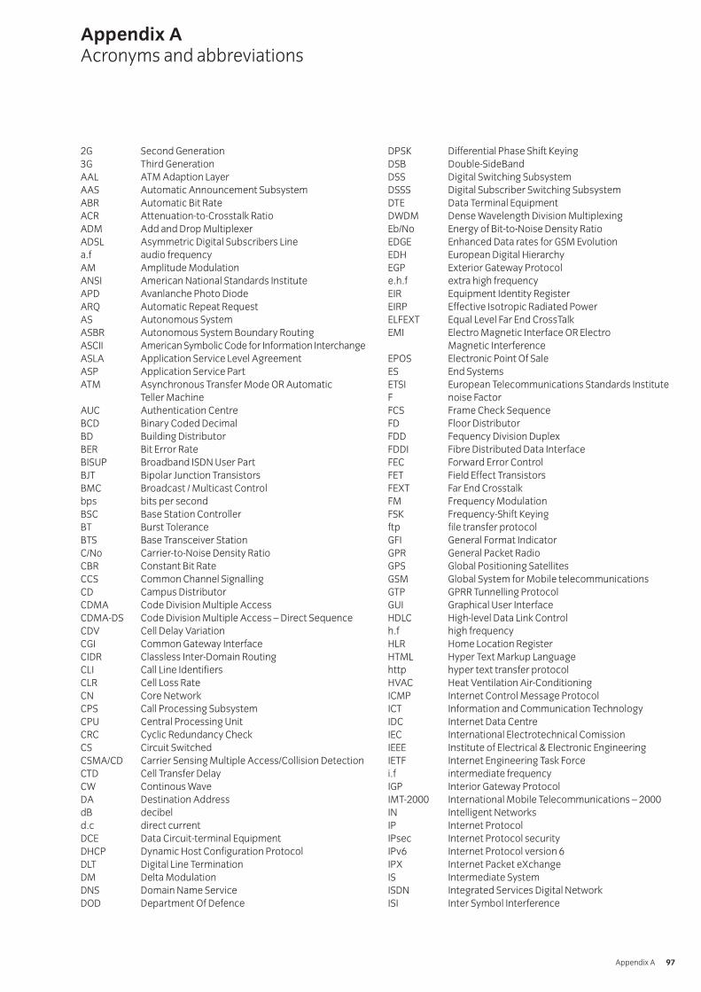
2G Second Generation3G Third GenerationAAL ATM Adaption LayerAAS Automatic Announcement SubsystemABR Automatic Bit RateACR Attenuation-to-Crosstalk RatioADM Add and Drop MultiplexerADSL Asymmetric Digital Subscribers Linea.f audio frequencyAM Amplitude ModulationANSI American National Standards InstituteAPD Avanlanche Photo DiodeARQ Automatic Repeat RequestAS Autonomous SystemASBR Autonomous System Boundary RoutingASCII American Symbolic Code for Information InterchangeASLA Application Service Level AgreementASP Application Service PartATM Asynchronous Transfer Mode OR Automatic
Teller MachineAUC Authentication CentreBCD Binary Coded DecimalBD Building DistributorBER Bit Error RateBISUP Broadband ISDN User PartBJT Bipolar Junction TransistorsBMC Broadcast / Multicast Controlbps bits per secondBSC Base Station ControllerBT Burst ToleranceBTS Base Transceiver StationC/No Carrier-to-Noise Density RatioCBR Constant Bit RateCCS Common Channel SignallingCD Campus DistributorCDMA Code Division Multiple AccessCDMA-DS Code Division Multiple Access – Direct SequenceCDV Cell Delay VariationCGI Common Gateway InterfaceCIDR Classless Inter-Domain RoutingCLI Call Line IdentifiersCLR Cell Loss RateCN Core NetworkCPS Call Processing SubsystemCPU Central Processing UnitCRC Cyclic Redundancy CheckCS Circuit SwitchedCSMA/CD Carrier Sensing Multiple Access/Collision DetectionCTD Cell Transfer DelayCW Continous WaveDA Destination AddressdB decibeld.c direct currentDCE Data Circuit-terminal EquipmentDHCP Dynamic Host Configuration ProtocolDLT Digital Line TerminationDM Delta ModulationDNS Domain Name ServiceDOD Department Of Defence
DPSK Differential Phase Shift KeyingDSB Double-SideBandDSS Digital Switching SubsystemDSSS Digital Subscriber Switching SubsystemDTE Data Terminal EquipmentDWDM Dense Wavelength Division MultiplexingEb/No Energy of Bit-to-Noise Density RatioEDGE Enhanced Data rates for GSM EvolutionEDH European Digital HierarchyEGP Exterior Gateway Protocole.h.f extra high frequencyEIR Equipment Identity RegisterEIRP Effective Isotropic Radiated PowerELFEXT Equal Level Far End CrossTalkEMI Electro Magnetic Interface OR Electro
Magnetic InterferenceEPOS Electronic Point Of SaleES End SystemsETSI European Telecommunications Standards InstituteF noise FactorFCS Frame Check SequenceFD Floor DistributorFDD Fequency Division DuplexFDDI Fibre Distributed Data InterfaceFEC Forward Error ControlFET Field Effect TransistorsFEXT Far End CrosstalkFM Frequency ModulationFSK Frequency-Shift Keyingftp file transfer protocolGFI General Format IndicatorGPR General Packet RadioGPS Global Positioning SatellitesGSM Global System for Mobile telecommunicationsGTP GPRR Tunnelling ProtocolGUI Graphical User InterfaceHDLC High-level Data Link Controlh.f high frequencyHLR Home Location RegisterHTML Hyper Text Markup Languagehttp hyper text transfer protocolHVAC Heat Ventilation Air-ConditioningICMP Internet Control Message ProtocolICT Information and Communication TechnologyIDC Internet Data CentreIEC International Electrotechnical ComissionIEEE Institute of Electrical & Electronic EngineeringIETF Internet Engineering Task Forcei.f intermediate frequencyIGP Interior Gateway ProtocolIMT-2000 International Mobile Telecommunications – 2000IN Intelligent NetworksIP Internet ProtocolIPsec Internet Protocol securityIPv6 Internet Protocol version 6IPX Internet Packet eXchangeIS Intermediate SystemISDN Integrated Services Digital NetworkISI Inter Symbol Interference
Appendix AAcronyms and abbreviations
Appendix A 97
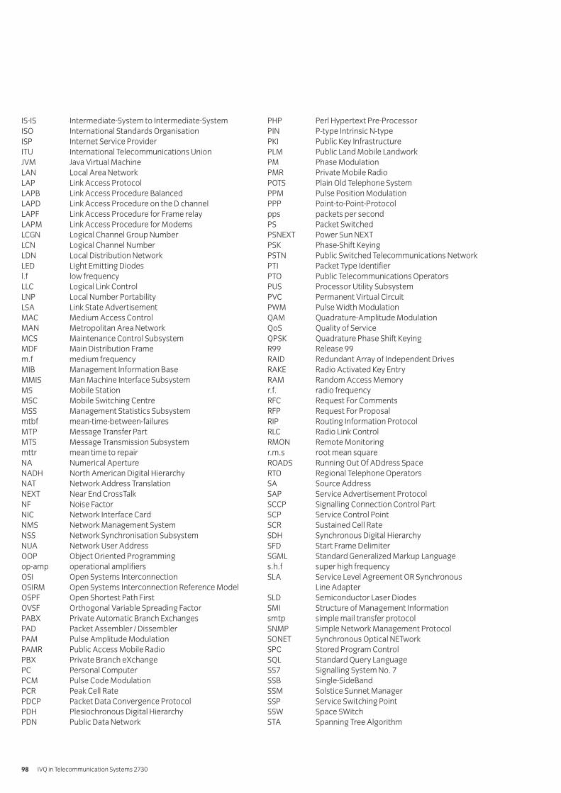
IS-IS Intermediate-System to Intermediate-SystemISO International Standards OrganisationISP Internet Service ProviderITU International Telecommunications UnionJVM Java Virtual MachineLAN Local Area NetworkLAP Link Access ProtocolLAPB Link Access Procedure BalancedLAPD Link Access Procedure on the D channelLAPF Link Access Procedure for Frame relayLAPM Link Access Procedure for ModemsLCGN Logical Channel Group NumberLCN Logical Channel NumberLDN Local Distribution NetworkLED Light Emitting Diodesl.f low frequencyLLC Logical Link ControlLNP Local Number PortabilityLSA Link State AdvertisementMAC Medium Access ControlMAN Metropolitan Area NetworkMCS Maintenance Control SubsystemMDF Main Distribution Framem.f medium frequencyMIB Management Information BaseMMIS Man Machine Interface SubsystemMS Mobile StationMSC Mobile Switching CentreMSS Management Statistics Subsystemmtbf mean-time-between-failuresMTP Message Transfer PartMTS Message Transmission Subsystemmttr mean time to repairNA Numerical ApertureNADH North American Digital HierarchyNAT Network Address TranslationNEXT Near End CrossTalkNF Noise FactorNIC Network Interface CardNMS Network Management SystemNSS Network Synchronisation SubsystemNUA Network User AddressOOP Object Oriented Programmingop-amp operational amplifiersOSI Open Systems InterconnectionOSIRM Open Systems Interconnection Reference ModelOSPF Open Shortest Path FirstOVSF Orthogonal Variable Spreading FactorPABX Private Automatic Branch ExchangesPAD Packet Assembler / DissemblerPAM Pulse Amplitude ModulationPAMR Public Access Mobile RadioPBX Private Branch eXchangePC Personal ComputerPCM Pulse Code ModulationPCR Peak Cell RatePDCP Packet Data Convergence ProtocolPDH Plesiochronous Digital HierarchyPDN Public Data Network
PHP Perl Hypertext Pre-ProcessorPIN P-type Intrinsic N-typePKI Public Key InfrastructurePLM Public Land Mobile LandworkPM Phase ModulationPMR Private Mobile RadioPOTS Plain Old Telephone SystemPPM Pulse Position ModulationPPP Point-to-Point-Protocolpps packets per secondPS Packet SwitchedPSNEXT Power Sun NEXTPSK Phase-Shift KeyingPSTN Public Switched Telecommunications NetworkPTI Packet Type IdentifierPTO Public Telecommunications OperatorsPUS Processor Utility SubsystemPVC Permanent Virtual CircuitPWM Pulse Width ModulationQAM Quadrature-Amplitude ModulationQoS Quality of ServiceQPSK Quadrature Phase Shift KeyingR99 Release 99RAID Redundant Array of Independent DrivesRAKE Radio Activated Key EntryRAM Random Access Memoryr.f. radio frequencyRFC Request For CommentsRFP Request For ProposalRIP Routing Information ProtocolRLC Radio Link ControlRMON Remote Monitoringr.m.s root mean squareROADS Running Out Of ADdress SpaceRTO Regional Telephone OperatorsSA Source AddressSAP Service Advertisement ProtocolSCCP Signalling Connection Control PartSCP Service Control PointSCR Sustained Cell RateSDH Synchronous Digital HierarchySFD Start Frame DelimiterSGML Standard Generalized Markup Languages.h.f super high frequencySLA Service Level Agreement OR Synchronous
Line AdapterSLD Semiconductor Laser DiodesSMI Structure of Management Informationsmtp simple mail transfer protocolSNMP Simple Network Management ProtocolSONET Synchronous Optical NETworkSPC Stored Program ControlSQL Standard Query LanguageSS7 Signalling System No. 7SSB Single-SideBandSSM Solstice Sunnet ManagerSSP Service Switching PointSSW Space SWitchSTA Spanning Tree Algorithm
IVQ in Telecommunication Systems 273098
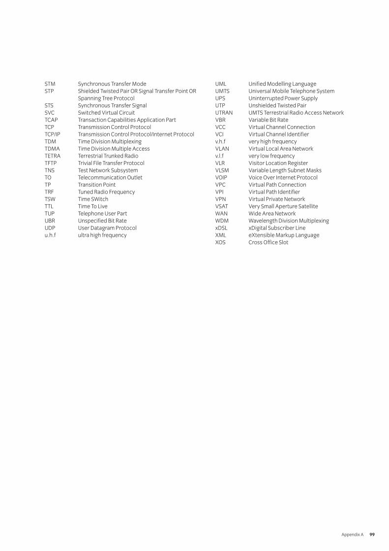
STM Synchronous Transfer ModeSTP Shielded Twisted Pair OR Signal Transfer Point OR
Spanning Tree ProtocolSTS Synchronous Transfer SignalSVC Switched Virtual CircuitTCAP Transaction Capabilities Application PartTCP Transmission Control ProtocolTCP/IP Transmission Control Protocol/Internet ProtocolTDM Time Division MultiplexingTDMA Time Division Multiple AccessTETRA Terrestrial Trunked RadioTFTP Trivial File Transfer ProtocolTNS Test Network SubsystemTO Telecommunication OutletTP Transition PointTRF Tuned Radio FrequencyTSW Time SWitchTTL Time To LiveTUP Telephone User PartUBR Unspecified Bit RateUDP User Datagram Protocolu.h.f ultra high frequency
UML Unified Modelling LanguageUMTS Universal Mobile Telephone SystemUPS Uninterrupted Power SupplyUTP Unshielded Twisted PairUTRAN UMTS Terrestrial Radio Access NetworkVBR Variable Bit RateVCC Virtual Channel ConnectionVCI Virtual Channel Identifierv.h.f very high frequencyVLAN Virtual Local Area Networkv.l.f very low frequencyVLR Visitor Location RegisterVLSM Variable Length Subnet MasksVOIP Voice Over Internet ProtocolVPC Virtual Path ConnectionVPI Virtual Path IdentifierVPN Virtual Private NetworkVSAT Very Small Aperture SatelliteWAN Wide Area NetworkWDM Wavelength Division MultiplexingxDSL xDigital Subscriber LineXML eXtensible Markup LanguageXOS Cross Office Slot
Appendix A 99

[ This page is intentionally blank]
City & Guilds has identified a list of minimum requirements for theTechnician Diploma in Telecommunication Systems. You shoulduse this list to make sure that you have the necessary resources tooffer the programme.
The visiting verifier should also use this list to check that allcandidates have access to the resources needed to be successful.You do not have to provide all the resources in one location, forexample you may have teaching rooms in one location and youmay use a different location (such as a workshop and laboratories)to provide access to resources that are not in the teaching rooms.
This list is intended to be appropriate to a wide range of locations.For example, electronic component catalogues may come from Internet sources that originate from the local or worldwide market.
Appendix BResource requirements
Appendix B 101
Accommodation• Teaching rooms, workshops and laboratories.• Layout of premises to allow for good work flow.
Equipment and tools• Scientific calculators• Personal computers• Ethernet network cards• Ethernet hub or switch• Category 5 cables with RJ45 connectors• Printers• Storage media• Software applications
• Software: word processing, database, spreadsheet, packetanalyser/sniffer
• Maps and local guide books• Electronic components
• Components:, resistors, capacitors, inductors, transformers,electromagnetic relays, semiconductor diodes, transistors(bipolar and field-effect), integrated circuits (linear), logicgates (AND, OR, NAND, NOR, Exclusive OR), connectors
• Test equipment• Equipment: power supplies, ammeters, voltmeters,
oscilloscopes, continuity testers, protocol analyser, networkanalyser, network simulator, optical power meters telephoneinstruments, modems, radio receivers (multiband),loudspeakers, microphones, television receivers,
• Communications media• Media: twin, multi-core/ multi-pair, ribbon cable, twisted pair
(shielded and unshielded), coaxial cables, waveguide, opticalfibres (mono-mode, multi-mode, graded-index); examples ofstructured cabling
• Electronic component catalogues• Catalogues: eg Farnell Electronic Components
(http://www.farnell.com/), RS Components(www1.rswww.com), Combined Precision Components(http://www.cpc.co.uk/), Maplin electronics(www.maplin.co.uk)
• Electronic component catalogues from (local) national orother international suppliers may be considered equivalent.
• Network component catalogues• Catalogues: eg Misco Networking
(http://www.misco.co.uk), Cisco (http://www.cisco.com),Extreme Networks (http://www.extremenetworks.com)
• Network component catalogues from (local) national or otherinternational suppliers.
• Network reference sites:http://www.iec.org/online/tutorials/,http://www.ietf.org/rfc.html, http://www.iso.org,http://standards.ieee.org/
• Reference books: See recommended reading list.
Diploma – resource list
IVQ in Telecommunication Systems 2730102
Two assessment methods are used in the 2730 Technician Awardsin Telecommunication Systems programme – written questionsand practical assignments.
Practical assignmentsEach unit or component in the diploma level of this programmehas one or more related practical assignments. Theseassignments may call on skills covered in other sections butreference is only made to the objectives covered by the markingcriteria. Wherever relevant, the option is given to you to use localnames, local standards, alternative measures and paper sizes, orto design an alternative assignment. Where this option is takenthe assignment must be of a comparable standard to ensureconsistency between centres using this programme. Theassignment must be documented and available to the visitingverifier. ALL assignments must be successfully completed.
The assignments may be administered at any time convenient tothe instructor and to the candidate.
The practical assignments in this publication are intended to be photocopied.
Instructor notesIt is essential that you read these before attempting to administerthe practical assignment. Practical assignments usually requireyou to prepare material for the assignment.
Candidate instructionsMake sure every candidate has a copy of these before beginningthe practical assignment.
MarkingThe marking is based on performance criteria or outcomesrelated to the practical assignment, to which the answer willalways be either ‘yes’ – the candidate achieved this or ‘no’ – thecandidate did not achieve this. Credit is given for thoseperformance objectives for which the answer is ‘yes’ – thecandidate achieved this.
SupervisionAll assignments require supervision and you must make sure thatthe results reflect only the individual candidate’s own work. Youmust keep all assessment documentation and material in a file foreach candidate until the results have been agreed by the visitingverifier and until confirmation of the result has been receivedfrom City & Guilds.
Records, results and certificationSuccessful completion of the related practical assignments for each unit or component needs to be recorded and then sent to City & Guilds. We suggest that you keep a record of each individual’s achievement that may then be transferred to the entry forms. A model is given at the end of this section but you may use any form of record keeping that is convenientand accessible.
In order to gain certification, results for successfully completedpractical assignments must be sent to City & Guilds. Results forpractical assignments are entered onto Form S that must becountersigned by the visiting verifier and sent to us.
An advantage of this programme is that candidates whosuccessfully complete the practical assignments for a single unitor component may, if they wish, claim a certificate of unit credit.This may be beneficial for those candidates who only wish tocomplete part of this programme. Send these claims to us at anytime provided the visiting verifier has countersigned the Form S.
Candidates wishing to gain the full award (certificate, diploma or advanced diploma) must successfully complete all forms of assessment. We recommend that the practical results are sent at the time of, or shortly before, the date of the written examinations.
Visiting verifierThe operation of this programme requires the appointment of avisiting verifier. The visiting verifier must countersign theresults of the practical assignments on Form S. The visitingverifier should also be able to inspect records and candidates’work to verify the results before submission.
Appendix CPractical assignments
Appendix C 103
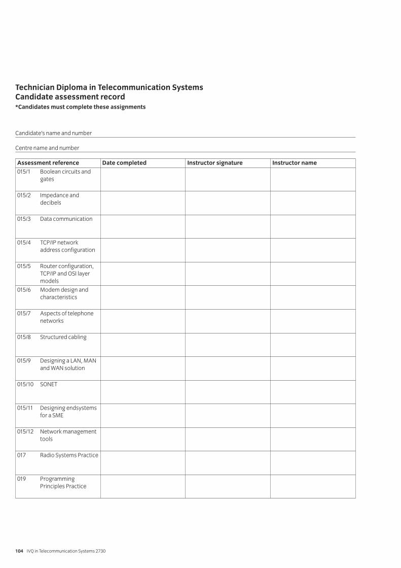
Technician Diploma in Telecommunication SystemsCandidate assessment record*Candidates must complete these assignments
IVQ in Telecommunication Systems 2730104
Candidate’s name and number
Centre name and number
Assessment reference Date completed Instructor signature Instructor name
015/1 Boolean circuits and gates
015/2 Impedance and decibels
015/3 Data communication
015/4 TCP/IP network address configuration
015/5 Router configuration, TCP/IP and OSI layer models
015/6 Modem design and characteristics
015/7 Aspects of telephone networks
015/8 Structured cabling
015/9 Designing a LAN, MAN and WAN solution
015/10 SONET
015/11 Designing endsystems for a SME
015/12 Network management tools
017 Radio Systems Practice
019 Programming Principles Practice
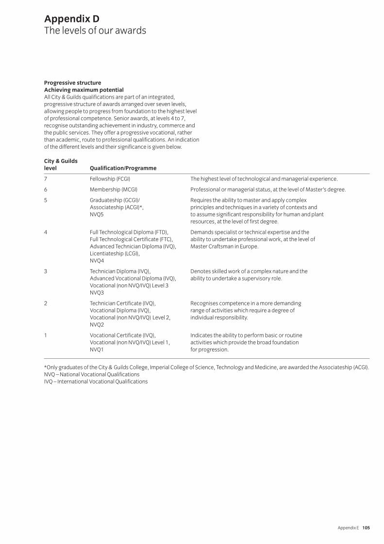
Progressive structureAchieving maximum potentialAll City & Guilds qualifications are part of an integrated,progressive structure of awards arranged over seven levels,allowing people to progress from foundation to the highest levelof professional competence. Senior awards, at levels 4 to 7,recognise outstanding achievement in industry, commerce andthe public services. They offer a progressive vocational, ratherthan academic, route to professional qualifications. An indicationof the different levels and their significance is given below.
Appendix DThe levels of our awards
Appendix E 105
City & Guildslevel Qualification/Programme
7 Fellowship (FCGI) The highest level of technological and managerial experience.
6 Membership (MCGI) Professional or managerial status, at the level of Master’s degree.
5 Graduateship (GCGI)/ Requires the ability to master and apply complexAssociateship (ACGI)*, principles and techniques in a variety of contexts andNVQ5 to assume significant responsibility for human and plant
resources, at the level of first degree.
4 Full Technological Diploma (FTD), Demands specialist or technical expertise and theFull Technological Certificate (FTC), ability to undertake professional work, at the level ofAdvanced Technician Diploma (IVQ), Master Craftsman in Europe.Licentiateship (LCGI),NVQ4
3 Technician Diploma (IVQ), Denotes skilled work of a complex nature and the Advanced Vocational Diploma (IVQ), ability to undertake a supervisory role.Vocational (non NVQ/IVQ) Level 3NVQ3
2 Technician Certificate (IVQ), Recognises competence in a more demanding Vocational Diploma (IVQ), range of activities which require a degree of Vocational (non NVQ/IVQ) Level 2, individual responsibility.NVQ2
1 Vocational Certificate (IVQ), Indicates the ability to perform basic or routine Vocational (non NVQ/IVQ) Level 1, activities which provide the broad foundation NVQ1 for progression.
*Only graduates of the City & Guilds College, Imperial College of Science, Technology and Medicine, are awarded the Associateship (ACGI).NVQ – National Vocational QualificationsIVQ – International Vocational Qualifications

[ This page is intentionally blank]
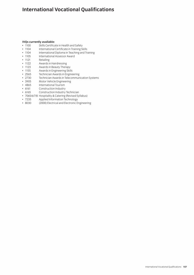
IVQs currently available:• 1100 Skills Certificate in Health and Safety• 1104 International Certificate in Training Skills• 1104 International Diploma in Teaching and Training• 1105 International Assessor Award• 1121 Retailing• 1122 Awards in Hairdressing• 1123 Awards in Beauty Therapy• 1155 Awards in Engineering Skills• 2565 Technician Awards in Engineering• 2730 Technician Awards in Telecommunication Systems• 3905 Motor Vehicle Engineering• 4865 International Tourism• 6161 Construction Industry• 6165 Construction Industry Technician• 7065/6/7/8 Hospitality & Catering (Revised Syllabus)• 7235 Applied Information Technology• 8030 (2000) Electrical and Electronic Engineering
International Vocational Qualifications
International Vocational Qualifications 107

[ This page is intentionally blank]


Published by City & Guilds1 Giltspur StreetLondonEC1A 9DDT +44 (0)20 7294 3505F +44 (0)20 7294 [email protected]
City & Guilds is a registered charity established to promote education and training
SP-02-2730