Embed Size (px)
Citation preview
Xenogen Corporation860 Atlantic AvenueAlameda, California 94501USAPhone (510) 291-6100 Fax (510) 291-6196www.xenogen.com
IVIS Lumina System Manual
IVIS Lumina System ManualFebruary 2006
®

For Research Use Only
Living Image® Software Manual
IVIS® Lumina System ManualFebruary 2006
© 2006 Xenogen Corporation. All rights reserved.
PN40150RevB
Xenogen Corporation860 Atlantic AvenueAlameda, California 94501, USAMain Phone: 1.510.291.6100Fax: 1.510.291.6196E-mail: [email protected]
Xenogen Technical Support 1.888.810.8055 (US only)1.510.291.6275 (International)
Discovery in the Living Organism, IVIS Imaging System and Living Image are either registered trademarks or trademarks of Xenogen Corporation. The names of companies and products mentioned herein may be the trademarks of their respective owners. Apple, Macintosh and QuickTime are registered trademarks of Apple Computer, Inc. Microsoft, PowerPoint and Windows are either registered trademarks or trademarks of Microsoft Corporation in the United States and/or other countries. Adobe and Illustrator are either registered trademarks or trademarks of Adobe Systems Incorporated in the United States and/or other countries.
i
IVIS® Lumina System Manual
Contents
1 Welcome . . . . . . . . . . . . . . . . . . . . . . . . . . . . . . . . . . . . . . . 11.1 Introduction . . . . . . . . . . . . . . . . . . . . . . . . . . . . . . . . . . . . . . . . 11.2 Xenogen Technical Support . . . . . . . . . . . . . . . . . . . . . . . . . . . . . . . . 2
2 Important Safety Instructions . . . . . . . . . . . . . . . . . . . . . . . . . . . 32.1 Definitions . . . . . . . . . . . . . . . . . . . . . . . . . . . . . . . . . . . . . . . . . 32.2 Instructions . . . . . . . . . . . . . . . . . . . . . . . . . . . . . . . . . . . . . . . . 42.3 Environmental Considerations for the System Components . . . . . . . . . . . . . . . 42.4 Cleaning or Moving the System Components . . . . . . . . . . . . . . . . . . . . . . . 52.5 Power Considerations . . . . . . . . . . . . . . . . . . . . . . . . . . . . . . . . . . . 52.6 Servicing . . . . . . . . . . . . . . . . . . . . . . . . . . . . . . . . . . . . . . . . . . 62.7 Other Equipment . . . . . . . . . . . . . . . . . . . . . . . . . . . . . . . . . . . . . 6
3 Warnings . . . . . . . . . . . . . . . . . . . . . . . . . . . . . . . . . . . . . . . 73.1 Electrical Safety . . . . . . . . . . . . . . . . . . . . . . . . . . . . . . . . . . . . . . 73.2 Eye Safety and Burn Hazard . . . . . . . . . . . . . . . . . . . . . . . . . . . . . . . 83.3 Mechanical Safety . . . . . . . . . . . . . . . . . . . . . . . . . . . . . . . . . . . . . 83.4 Chemical & Biological Safety . . . . . . . . . . . . . . . . . . . . . . . . . . . . . . . 93.5 Panels, Cover, and Modules . . . . . . . . . . . . . . . . . . . . . . . . . . . . . . . . 9
4 Legal Notices . . . . . . . . . . . . . . . . . . . . . . . . . . . . . . . . . . . . 114.1 Limited Warranty . . . . . . . . . . . . . . . . . . . . . . . . . . . . . . . . . . . . 114.2 Patents . . . . . . . . . . . . . . . . . . . . . . . . . . . . . . . . . . . . . . . . . . 124.3 Trademarks . . . . . . . . . . . . . . . . . . . . . . . . . . . . . . . . . . . . . . . 13
5 IVIS® Lumina Components & Specifications . . . . . . . . . . . . . . . . . 155.1 CCD Camera . . . . . . . . . . . . . . . . . . . . . . . . . . . . . . . . . . . . . . 165.2 Imaging Chamber . . . . . . . . . . . . . . . . . . . . . . . . . . . . . . . . . . . . 165.3 Optics . . . . . . . . . . . . . . . . . . . . . . . . . . . . . . . . . . . . . . . . . . 185.4 Optical Filter Wheel . . . . . . . . . . . . . . . . . . . . . . . . . . . . . . . . . . . 185.5 Acquisition Computer . . . . . . . . . . . . . . . . . . . . . . . . . . . . . . . . . . 185.6 Environmental Requirements . . . . . . . . . . . . . . . . . . . . . . . . . . . . . . 19
6 Operating the IVIS® Lumina . . . . . . . . . . . . . . . . . . . . . . . . . . . 216.1 System Start Up . . . . . . . . . . . . . . . . . . . . . . . . . . . . . . . . . . . . . 216.2 Restarting the System After a Power Outage . . . . . . . . . . . . . . . . . . . . . . 226.3 Gas Plumbing . . . . . . . . . . . . . . . . . . . . . . . . . . . . . . . . . . . . . . 226.4 Door Operation . . . . . . . . . . . . . . . . . . . . . . . . . . . . . . . . . . . . . 246.5 Imaging Basics . . . . . . . . . . . . . . . . . . . . . . . . . . . . . . . . . . . . . 256.6 System Shut Down Procedure . . . . . . . . . . . . . . . . . . . . . . . . . . . . . . 26
7 Care & Maintenance . . . . . . . . . . . . . . . . . . . . . . . . . . . . . . . . 277.1 Cleaning the IVIS Lumina . . . . . . . . . . . . . . . . . . . . . . . . . . . . . . . 27
8 Troubleshooting . . . . . . . . . . . . . . . . . . . . . . . . . . . . . . . . . . 298.1 Measured Temperature Does Not Equal the Demand Temperature . . . . . . . . . . 29
Contents
ii
8.2 Photographic Image Is Unacceptable . . . . . . . . . . . . . . . . . . . . . . . . . . 308.3 Luminescent Image Is Unacceptable . . . . . . . . . . . . . . . . . . . . . . . . . . 318.4 No Image Is Produced . . . . . . . . . . . . . . . . . . . . . . . . . . . . . . . . . . 32
9 XFO-12 Fluorescence Equipment . . . . . . . . . . . . . . . . . . . . . . . . 339.1 Installation Requirements . . . . . . . . . . . . . . . . . . . . . . . . . . . . . . . . 349.2 Specifications . . . . . . . . . . . . . . . . . . . . . . . . . . . . . . . . . . . . . . 349.3 Description and Theory of Operation . . . . . . . . . . . . . . . . . . . . . . . . . . 359.4 Acquiring Fluorescent Images . . . . . . . . . . . . . . . . . . . . . . . . . . . . . 409.5 Troubleshooting . . . . . . . . . . . . . . . . . . . . . . . . . . . . . . . . . . . . . 429.6 Care and Maintenance of the XFO-12 Fluorescence Equipment . . . . . . . . . . . . 469.7 XFO-12 Hardware Replacement Parts List . . . . . . . . . . . . . . . . . . . . . . . 47
Appendix A: Moving IVIS® Lumina With the XWS-260 Workstation . . . . . . 49
Index . . . . . . . . . . . . . . . . . . . . . . . . . . . . . . . . . . . . . . . . . . 51
1
IVIS® Lumina System Manual
1 Welcome
Introduction . . . . . . . . . . . . . . . . . . . . . . . . . . . . . 1Xenogen Technical Support . . . . . . . . . . . . . . . . . . . . 2
1.1 Introduction
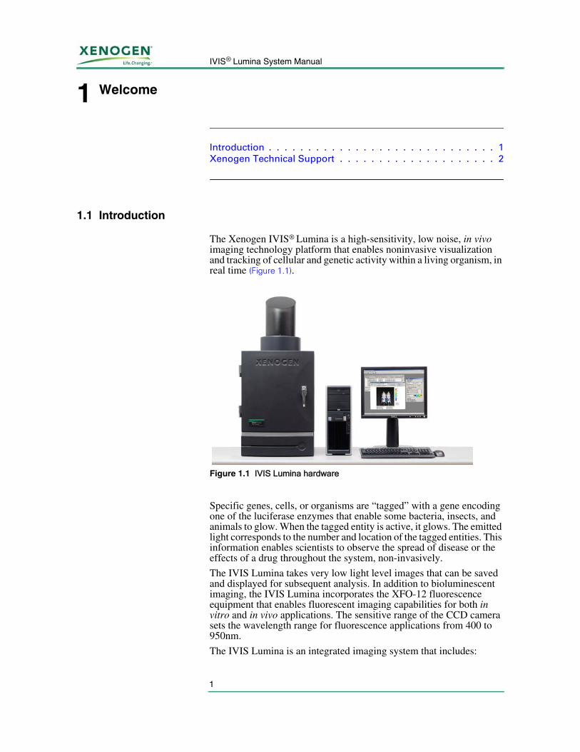
The Xenogen IVIS® Lumina is a high-sensitivity, low noise, in vivo imaging technology platform that enables noninvasive visualization and tracking of cellular and genetic activity within a living organism, in real time (Figure 1.1).
Specific genes, cells, or organisms are “tagged” with a gene encoding one of the luciferase enzymes that enable some bacteria, insects, and animals to glow. When the tagged entity is active, it glows. The emitted light corresponds to the number and location of the tagged entities. This information enables scientists to observe the spread of disease or the effects of a drug throughout the system, non-invasively.
The IVIS Lumina takes very low light level images that can be saved and displayed for subsequent analysis. In addition to bioluminescent imaging, the IVIS Lumina incorporates the XFO-12 fluorescence equipment that enables fluorescent imaging capabilities for both in vitro and in vivo applications. The sensitive range of the CCD camera sets the wavelength range for fluorescence applications from 400 to 950nm.
The IVIS Lumina is an integrated imaging system that includes:
Figure 1.1 IVIS Lumina hardware
1. Welcome
2
• A scientific grade thermoelectrically cooled CCD camera mounted on a light-tight imaging chamber
• A camera power supply
• A Windows®-based computer system for data acquisition and analysis
• The XFO-12 fluorescence equipment
This manual explains how to operate and maintain the equipment, and provides guidelines for obtaining the best bioluminescent or fluorescent images. Before using the IVIS® Lumina, please read this manual carefully to obtain safe, optimum performance and a maximum service life from the unit.
For instructions on how to acquire fluorescent images using the XFO-12 fluorescence equipment, please see Chapter 9, page 33. For instructions on using the system software, please see the Living Image® Software User’s Manual.
If you have questions regarding this manual or the IVIS Lumina, please call Xenogen technical support.
1.2 Xenogen Technical Support
Technical Support: 1.888.810.8055 (US)1.510.291.6275 (International)
Main Telephone: 1.510.291.6100
E-mail: [email protected]
Fax: 1.510.291.6196
Address: Xenogen Corporation860 Atlantic AvenueAlameda, CA 94501
3
IVIS® Lumina System Manual
2 Important Safety Instructions
Definitions . . . . . . . . . . . . . . . . . . . . . . . . . . . . . . 3Instructions . . . . . . . . . . . . . . . . . . . . . . . . . . . . . 4Environmental Considerations for the System Components . . . . . . 4Cleaning or Moving the System Components . . . . . . . . . . . . . . . 5Power Considerations . . . . . . . . . . . . . . . . . . . . . . . . . . . . . 5Servicing . . . . . . . . . . . . . . . . . . . . . . . . . . . . . . . . . . . . . 6Other Equipment . . . . . . . . . . . . . . . . . . . . . . . . . . . . . . . . 6
2.1 Definitions
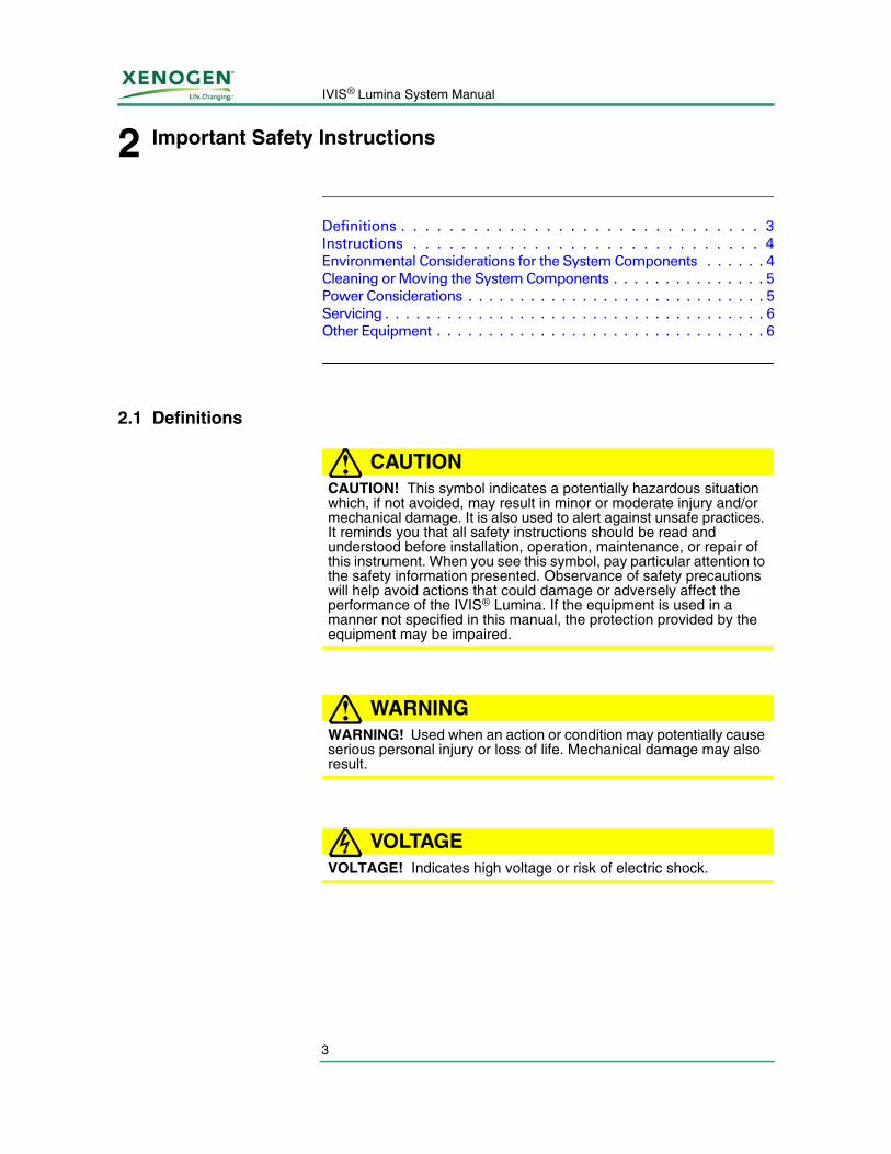
CAUTION!CAUTION! This symbol indicates a potentially hazardous situation which, if not avoided, may result in minor or moderate injury and/or mechanical damage. It is also used to alert against unsafe practices. It reminds you that all safety instructions should be read and understood before installation, operation, maintenance, or repair of this instrument. When you see this symbol, pay particular attention to the safety information presented. Observance of safety precautions will help avoid actions that could damage or adversely affect the performance of the IVIS® Lumina. If the equipment is used in a manner not specified in this manual, the protection provided by the equipment may be impaired.
WARNING!WARNING! Used when an action or condition may potentially cause serious personal injury or loss of life. Mechanical damage may also result.
VOLTAGEVOLTAGE! Indicates high voltage or risk of electric shock.
2. Important Safety Instructions
4
2.2 Instructions
Read Instructions Read and understand all the safety and operating instructions before you install, operate, or perform maintenance on this product. Make sure that you fully understand the following safety instructions, warnings, and disclaimers before proceeding to the rest of the manual.
Retain Instructions Retain the safety and operating instructions for future reference.
Follow Instructions Follow all operating and handling instructions. Failure to follow operating or handling instructions may void any warranty covering this product.
Heed Warnings Abide by all warnings on the product and in the operating instructions. Failure to adhere to warnings or safety precautions may void any warranty covering this product.
2.3 Environmental Considerations for the System Components
Location for the IVIS® Lumina
Before the IVIS Lumina is installed, consider the proper environment for the components.
Install the equipment in an environment where:
• The temperature does not fluctuate widely and is maintained between 15-25° C.
• The humidity does not exceed 80%.
• No strong electric or magnetic fields exist.
• No vibrations are present.
• No corrosive gases are present.
• High amounts of dust are not present.
• No open flame is present.
• There is sufficient space behind the IVIS Lumina equipment. A minimum space of four inches from the flat surface of the rear panel should be provided behind the IVIS Lumina to provide unobstructed air flow and access to the main power on/off switch.
• The work space is level.
Heat The system should be situated away from heat sources such as open flames, radiators, heat registers, stoves, and other heat-generating electrical equipment.
5
IVIS® Lumina System Manual
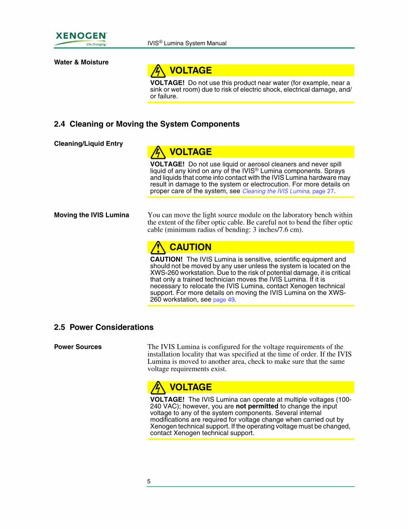
Water & MoistureVOLTAGE
VOLTAGE! Do not use this product near water (for example, near a sink or wet room) due to risk of electric shock, electrical damage, and/or failure.
2.4 Cleaning or Moving the System Components
Cleaning/Liquid EntryVOLTAGE
VOLTAGE! Do not use liquid or aerosol cleaners and never spill liquid of any kind on any of the IVIS® Lumina components. Sprays and liquids that come into contact with the IVIS Lumina hardware may result in damage to the system or electrocution. For more details on proper care of the system, see Cleaning the IVIS Lumina, page 27.
Moving the IVIS Lumina You can move the light source module on the laboratory bench within the extent of the fiber optic cable. Be careful not to bend the fiber optic cable (minimum radius of bending: 3 inches/7.6 cm).
CAUTION!CAUTION! The IVIS Lumina is sensitive, scientific equipment and should not be moved by any user unless the system is located on the XWS-260 workstation. Due to the risk of potential damage, it is critical that only a trained technician moves the IVIS Lumina. If it is necessary to relocate the IVIS Lumina, contact Xenogen technical support. For more details on moving the IVIS Lumina on the XWS-260 workstation, see page 49.
2.5 Power Considerations
Power Sources The IVIS Lumina is configured for the voltage requirements of the installation locality that was specified at the time of order. If the IVIS Lumina is moved to another area, check to make sure that the same voltage requirements exist.
VOLTAGEVOLTAGE! The IVIS Lumina can operate at multiple voltages (100-240 VAC); however, you are not permitted to change the input voltage to any of the system components. Several internal modifications are required for voltage change when carried out by Xenogen technical support. If the operating voltage must be changed, contact Xenogen technical support.
2. Important Safety Instructions
6
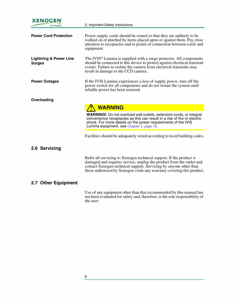
Power Cord Protection Power supply cords should be routed so that they are unlikely to be walked on or pinched by items placed upon or against them. Pay close attention to receptacles and to points of connection between cords and equipment.
Lightning & Power Line Surges
The IVIS® Lumina is supplied with a surge protector. All components should be connected to this device to protect against electrical transient events. Failure to isolate the camera from electrical transients may result in damage to the CCD camera.
Power Outages If the IVIS Lumina experiences a loss of supply power, turn off the power switch for all components and do not restart the system until reliable power has been restored.
Overloading
WARNING!WARNING! Do not overload wall outlets, extension cords, or integral convenience receptacles as this can result in a risk of fire or electric shock. For more details on the power requirements of the IVIS Lumina equipment, see Chapter 5, page 15.
Facilities should be adequately wired according to local building codes.
2.6 Servicing
Refer all servicing to Xenogen technical support. If the product is damaged and requires service, unplug the product from the outlet and contact Xenogen technical support. Servicing by anyone other than those authorized by Xenogen voids any warranty covering this product.
2.7 Other Equipment
Use of any equipment other than that recommended by this manual has not been evaluated for safety and, therefore, is the sole responsibility of the user.
7
IVIS® Lumina System Manual
3 Warnings
Electrical Safety . . . . . . . . . . . . . . . . . . . . . . . . . . . 7Eye Safety and Burn Hazard . . . . . . . . . . . . . . . . . . . . 8Mechanical Safety . . . . . . . . . . . . . . . . . . . . . . . . . 8Chemical & Biological Safety . . . . . . . . . . . . . . . . . . . 9Panels, Cover, and Modules . . . . . . . . . . . . . . . . . . . . 9
3.1 Electrical Safety
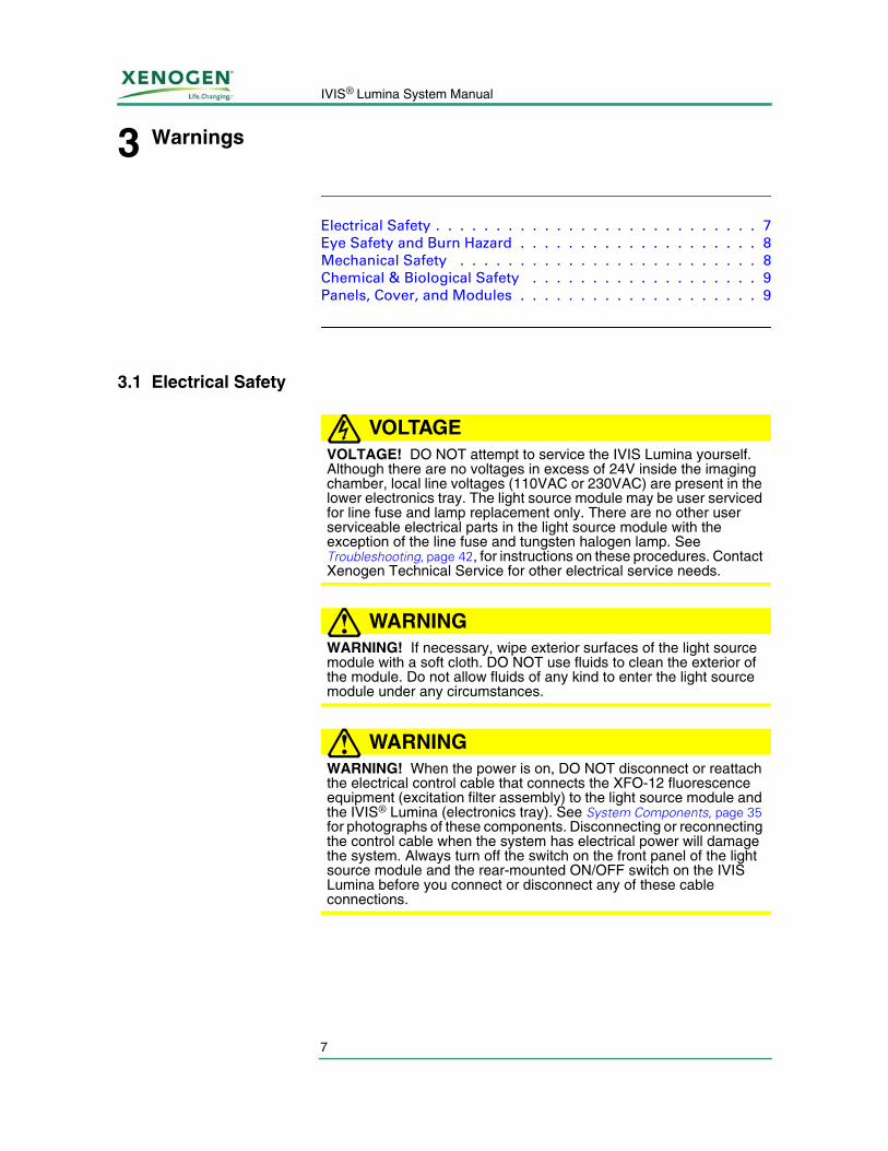
VOLTAGEVOLTAGE! DO NOT attempt to service the IVIS Lumina yourself. Although there are no voltages in excess of 24V inside the imaging chamber, local line voltages (110VAC or 230VAC) are present in the lower electronics tray. The light source module may be user serviced for line fuse and lamp replacement only. There are no other user serviceable electrical parts in the light source module with the exception of the line fuse and tungsten halogen lamp. See Troubleshooting, page 42, for instructions on these procedures. Contact Xenogen Technical Service for other electrical service needs.
WARNING!WARNING! If necessary, wipe exterior surfaces of the light source module with a soft cloth. DO NOT use fluids to clean the exterior of the module. Do not allow fluids of any kind to enter the light source module under any circumstances.
WARNING!WARNING! When the power is on, DO NOT disconnect or reattach the electrical control cable that connects the XFO-12 fluorescence equipment (excitation filter assembly) to the light source module and the IVIS® Lumina (electronics tray). See System Components, page 35 for photographs of these components. Disconnecting or reconnecting the control cable when the system has electrical power will damage the system. Always turn off the switch on the front panel of the light source module and the rear-mounted ON/OFF switch on the IVIS Lumina before you connect or disconnect any of these cable connections.
3. Warnings
8
3.2 Eye Safety and Burn Hazard
The light source module and the connecting fiber optic cables produce intense light that can cause eye damage. The module uses a tungsten halogen lamp bulb that operates at a high temperature, which if exposed to a user's skin, could cause a burn.
WARNING!WARNING! DO NOT operate the light source module or the XFO-12 fluorescence equipment without all of the fiber optic cables connected at both of their end connections.
WARNING!WARNING! If you need to replace the tungsten halogen lamp or lamp assembly in the light source module, wait until the lamp and socket are cool. Confirm that the components are cool before proceeding. See Lamp Replacement, page 44.
3.3 Mechanical Safety
The imaging chamber of the IVIS Lumina is heavy and weighs 90 lbs. (41 kg).
The IVIS Lumina has many internal motorized components that can move at any time. The imaging stage can move when the door is open. Care should be taken to keep hands and equipment away from the sides of the platform when it is moving. Never place anything underneath the platform.
Do not attempt to put anything into the lens opening of the camera as there are optical components that can be compromised or damaged.
If the imaging chamber makes an unusual noise or appears to be jammed, turn off the power switch located on the back of the chamber.
WARNING!WARNING! If the gas hoses become caught, kinked, or disconnected, do not operate the instrument. Overexposure to anesthesia gas may occur.
!IMPORTANT
Do not move the IVIS Lumina after installation. If you need to move the IVIS Lumina, contact Xenogen technical support for assistance.
9
IVIS® Lumina System Manual
CAUTION!CAUTION! DO NOT touch or expose the four diffusing reflectors and the exposed emission filter to contaminants (described in System Components, page 35 and shown in Figure 9.2), otherwise imaging performance may be impaired. The reflectors' surfaces have been surface treated for optimum light diffusion.
CAUTION!CAUTION! The Living Image® software controls excitation filter selection. Do not manually turn the numbered knob on the Excitation Filter Wheel Assembly (see Figure 9.5, page 37).
3.4 Chemical & Biological Safety
Normal operation may involve the use of test samples that are pathogenic, toxic, or radioactive. It is your responsibility to ensure that all necessary safety precautions are taken before such materials are used.
Dispose of all waste materials according to appropriate environmental health and safety guidelines.
It is your responsibility to decontaminate the IVIS® Lumina before requesting service by Xenogen technical support. Ask your laboratory safety officer to advise you about the level of containment required for your application and about the proper decontamination or sterilization procedures to follow.
Handle all infectious samples according to good laboratory procedures and methods to prevent the spread of disease.
3.5 Panels, Cover, and Modules
There are no user serviceable components in the lower electronics tray of the IVIS® Lumina. Do not remove the electronics tray from the IVIS Lumina or the cover from the light source module unless you are instructed by and under the supervision of a Xenogen technical service representative.
The only exception to this is removing the light source module front panel mounted lamp assembly for tungsten halogen lamp replacement (see page 44).

3. Warnings
10
[This page intentionally left blank.]
11
IVIS® Lumina System Manual
4 Legal Notices
Limited Warranty . . . . . . . . . . . . . . . . . . . . . . . . . 11Patents . . . . . . . . . . . . . . . . . . . . . . . . . . . . . . 12Trademarks . . . . . . . . . . . . . . . . . . . . . . . . . . . . 13
4.1 Limited Warranty
Xenogen Corporation ("Xenogen") provides the following limited warranty for each new IVIS® Lumina ("System") purchased from it as follows ("Limited Warranty"):
i. This Limited Warranty for the System extends for a period of one (1) year following delivery to, and installation of, the System to the original customer, purchaser, or user ("Customer") and is not assignable or transferable to any successor.
ii. During the Limited Warranty period, Xenogen will repair or replace, at Xenogen's sole option, any defective parts if such repair or replacement is needed because of System malfunction or failure during normal usage in accordance with the instructions in this manual. Repairs and replacements under the Limited Warranty will be made at Xenogen's expense. Xenogen's limit of liability under the Limited Warranty shall be the purchase price of the Imaging System. Xenogen shall not be liable for any other losses or damages. These remedies are the Customer's exclusive remedies for breach of warranty.
iii. No coverage or benefits shall be provided under this Limited Warranty if any of the following conditions apply:
a.The System has been subjected to abnormal use, abnormal conditions, unauthorized modifications (e.g., unauthorized installation of hardware or software), unauthorized repair or servicing, misuse, neglect, abuse, accident, alteration, any use inconsistent with or in contradiction to the instructions in this manual, or other acts which are not the fault of Xenogen.
b.Xenogen was not advised in writing by the Customer of the alleged defect or malfunction of the System within ten (10) days after the expiration of the applicable limited warranty period.
iv. If a problem develops during the Limited Warranty period, the Customer shall contact Xenogen technical support for assistance.
v. THE FOREGOING LIMITED WARRANTY IS THE CUSTOMER'S SOLE AND EXCLUSIVE REMEDY AND IS IN LIEU OF ALL OTHER WARRANTIES, EXPRESS OR IMPLIED. XENOGEN SHALL NOT BE LIABLE FOR SPECIAL, INCIDENTAL OR CONSEQUENTIAL DAMAGES, INCLUDING BUT NOT LIMITED TO LOSS OF ANTICIPATED BENEFITS OR PROFITS, LOSS OF SAVINGS
4. Legal Notices
12
OR REVENUE, PUNITIVE DAMAGES, LOSS OF USE OF THE SYSTEM OR ANY ASSOCIATED EQUIPMENT, COST OF CAPITAL, COST OF ANY SUBSTITUTE EQUIPMENT OR FACILITIES, DOWNTIME, THE CLAIMS OF ANY THIRD PARTIES, INCLUDING CUSTOMERS, AND INJURY TO PROPERTY, RESULTING FROM THE PURCHASE OR USE OF THE SYSTEM OR ARISING FROM BREACH OF THE WARRANTY, BREACH OF CONTRACT, NEGLIGENCE, STRICT TORT, OR ANY OTHER LEGAL OR EQUITABLE THEORY, EVEN IF XENOGEN KNEW OF THE LIKELIHOOD OF SUCH DAMAGES. XENOGEN SHALL NOT BE LIABLE FOR DELAY IN RENDERING SERVICE UNDER THE LIMITED WARRANTY, OR LOSS OF USE DURING THE PERIOD THAT THE SYSTEM IS BEING REPAIRED.
vi. Some countries, states or provinces do not allow the exclusion or limitation of implied warranties or the limitation of incidental or consequential damages for certain products or the limitation of liability for personal injury, so the above limitations and exclusions may be limited in their application to you. When any implied warranties are not allowed to be excluded in their entirety, they will be limited to the duration of the applicable written warranty. This Limited Warranty gives you specific legal rights which may vary depending on local law.
vii. This Limited Warranty shall be governed by the laws of the State of California, U.S.A., excluding its conflicts of laws principles and excluding the United Nations Convention on Contracts for the International Sale of Goods.
4.2 Patents
The detection and imaging of light originating within mammals is the subject of several issued patents and pending patent applications in the United States and around the world, including U.S. Patent Numbers 5,650,135, 6,217,847, 6,649,143, 6,890,515, and European Patent Commission Number EP0861093, for which Xenogen Corporation is the exclusive licensor. The use of an IVIS® Imaging System for such applications requires a sublicense from Xenogen Corporation.
In addition, many of the hardware and software components of the Imaging System are the subject of various issued patents and pending patent applications owned by Xenogen, including: United States Patent Number 6,614,452 (Graphical User Interface for In Vivo Imaging) and 6,775,567 (Improved Imaging Apparatus); and United States Patent Applications 09/905668 (Multi-view Imaging Systems), 10/606976 (Method and Apparatus for 3-D Reconstruction of Light Emitting Sources), 10/151463 (Method and Apparatus for Determining Target Depth, Brightness, and Size Within a Body Region), 10/189886 (Fluorescence illumination assembly for an imaging apparatus), and 10/068573 (Light calibration device for use in low level light imaging systems).
13
IVIS® Lumina System Manual
4.3 Trademarks
IVIS and Living Image are registered trademarks of Xenogen Corporation. The names of companies and products mentioned herein may be the trademarks of their respective owners. Microsoft and Windows are either registered trademarks or trademarks of Microsoft Corporation in the United States and/or other countries. Pentium III is a registered trademark of Intel Corporation.

4. Legal Notices
14
[This page intentionally left blank.]
15
IVIS® Lumina System Manual
5 IVIS® Lumina Components & Specifications
CCD Camera . . . . . . . . . . . . . . . . . . . . . . . . . . . 16Imaging Chamber . . . . . . . . . . . . . . . . . . . . . . . . 16Optics . . . . . . . . . . . . . . . . . . . . . . . . . . . . . . . 18Optics . . . . . . . . . . . . . . . . . . . . . . . . . . . . . . . 18Acquisition Computer . . . . . . . . . . . . . . . . . . . . . . 18Environmental Requirements . . . . . . . . . . . . . . . . . . 19
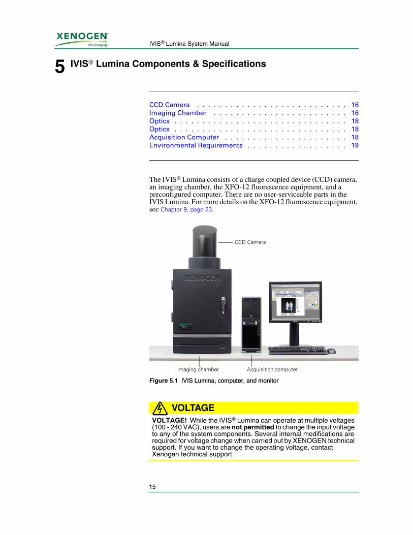
The IVIS® Lumina consists of a charge coupled device (CCD) camera, an imaging chamber, the XFO-12 fluorescence equipment, and a preconfigured computer. There are no user-serviceable parts in the IVIS Lumina. For more details on the XFO-12 fluorescence equipment, see Chapter 9, page 33.
VOLTAGEVOLTAGE! While the IVIS® Lumina can operate at multiple voltages (100 - 240 VAC), users are not permitted to change the input voltage to any of the system components. Several internal modifications are required for voltage change when carried out by XENOGEN technical support. If you want to change the operating voltage, contact Xenogen technical support.
Figure 5.1 IVIS Lumina, computer, and monitor
Acquisition computerImaging chamber
CCD Camera
5. IVIS® Lumina Components & Specifications
16
If you have any questions, please contact Xenogen technical support.
5.1 CCD Camera
The camera is a scientific grade, back-thinned, back-illuminated, large format CCD manufactured by Andor Technologies (Figure 5.1).
CCD Camera Features • Low dark current
• Thermoelectrically cooled
• 16 bit CCD digitization
• Low-noise electronic readout for extremely low-background images
CCD Camera Specifications
5.2 Imaging Chamber
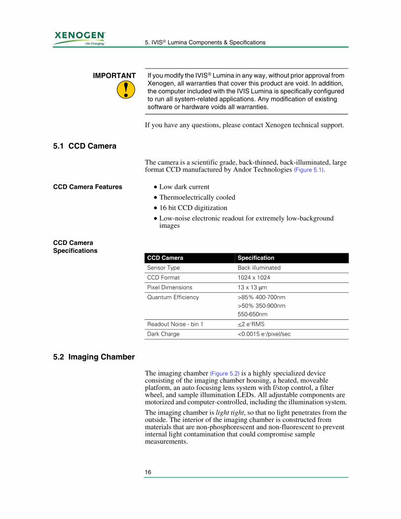
The imaging chamber (Figure 5.2) is a highly specialized device consisting of the imaging chamber housing, a heated, moveable platform, an auto focusing lens system with f/stop control, a filter wheel, and sample illumination LEDs. All adjustable components are motorized and computer-controlled, including the illumination system.
The imaging chamber is light tight, so that no light penetrates from the outside. The interior of the imaging chamber is constructed from materials that are non-phosphorescent and non-fluorescent to prevent internal light contamination that could compromise sample measurements.
!IMPORTANT If you modify the IVIS® Lumina in any way, without prior approval from
Xenogen, all warranties that cover this product are void. In addition, the computer included with the IVIS Lumina is specifically configured to run all system-related applications. Any modification of existing software or hardware voids all warranties.
CCD Camera Specification
Sensor Type Back illuminated
CCD Format 1024 x 1024
Pixel Dimensions 13 x 13 μm
Quantum Efficiency >85% 400-700nm>50% 350-900nm550-650nm
Readout Noise - bin 1 <2 e-RMS
Dark Charge <0.0015 e-/pixel/sec
17
IVIS® Lumina System Manual
WARNING!WARNING! Under no circumstances should you attempt to make any mechanical modifications to the imaging chamber.
Imaging Chamber Features
• Custom zero-background imaging chamber
• Eight position optical filter emission wheel and a 12 position excitation filter wheel
• High-efficiency lens assembly
• Sample illumination system
• f/stop control
• Heated and regulated sample shelf temperature to reduce stress on an animal under anesthesia
• Gas anesthesia manifold, including gas delivery and exhaust plumbing
• Software-controlled field of view, f-stop, focus, and optical filter wheel
Imaging Chamber Specifications
Figure 5.2 IVIS® Lumina imaging chamber
IVIS® Lumina Imaging Chamber Description
Power requirements 4.0 A max at 120 V 2.0 A max at 240 V 50-60 Hz
Dimensions 19” x 28” x 39” 48 cm x 71 cm x 100 cm
Door opening dimensions 15” x 20.25” 38 cm x 51 cm
Weight 90 lbs 41 Kg
5. IVIS® Lumina Components & Specifications
18
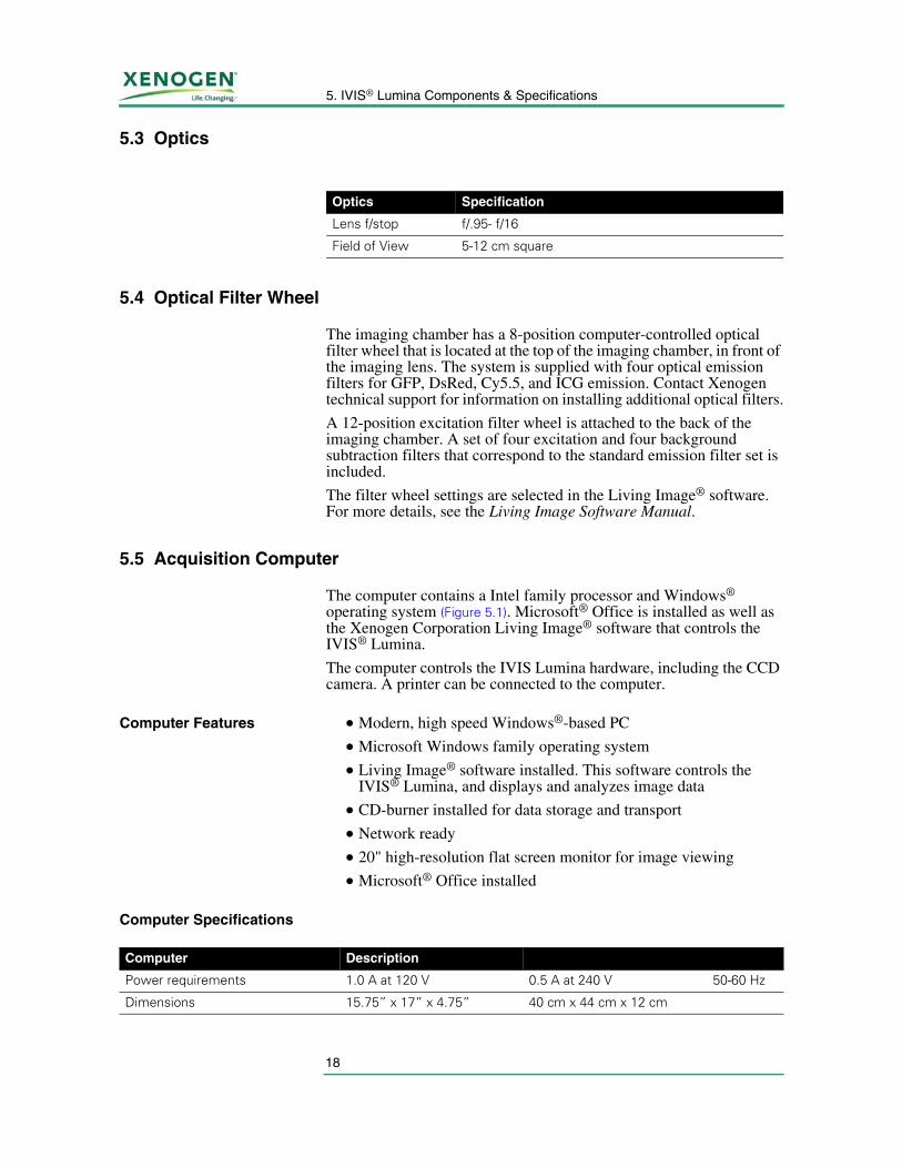
5.3 Optics
5.4 Optical Filter Wheel
The imaging chamber has a 8-position computer-controlled optical filter wheel that is located at the top of the imaging chamber, in front of the imaging lens. The system is supplied with four optical emission filters for GFP, DsRed, Cy5.5, and ICG emission. Contact Xenogen technical support for information on installing additional optical filters.
A 12-position excitation filter wheel is attached to the back of the imaging chamber. A set of four excitation and four background subtraction filters that correspond to the standard emission filter set is included.
The filter wheel settings are selected in the Living Image® software. For more details, see the Living Image Software Manual.
5.5 Acquisition Computer
The computer contains a Intel family processor and Windows® operating system (Figure 5.1). Microsoft® Office is installed as well as the Xenogen Corporation Living Image® software that controls the IVIS® Lumina.
The computer controls the IVIS Lumina hardware, including the CCD camera. A printer can be connected to the computer.
Computer Features • Modern, high speed Windows®-based PC
• Microsoft Windows family operating system
• Living Image® software installed. This software controls the IVIS® Lumina, and displays and analyzes image data
• CD-burner installed for data storage and transport
• Network ready
• 20" high-resolution flat screen monitor for image viewing
• Microsoft® Office installed
Computer Specifications
Optics Specification
Lens f/stop f/.95- f/16
Field of View 5-12 cm square
Computer Description
Power requirements 1.0 A at 120 V 0.5 A at 240 V 50-60 Hz
Dimensions 15.75” x 17” x 4.75” 40 cm x 44 cm x 12 cm
19
IVIS® Lumina System Manual
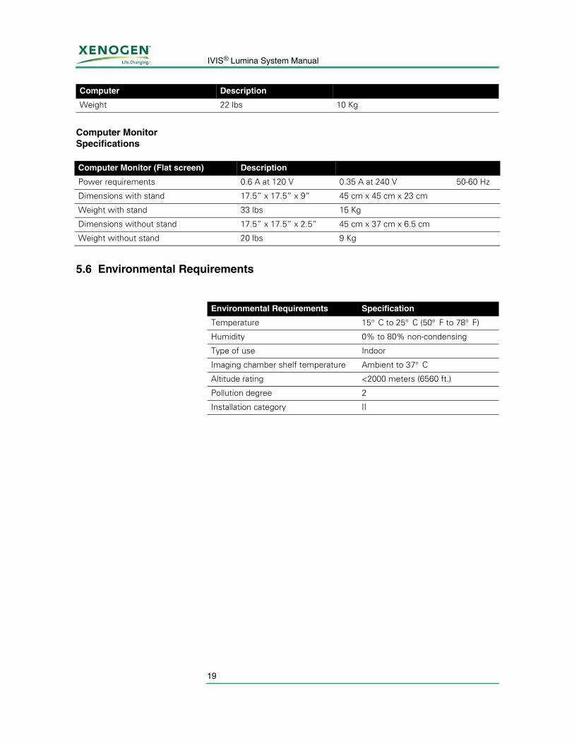
Computer Monitor Specifications
5.6 Environmental Requirements
Weight 22 lbs 10 Kg
Computer Description
Computer Monitor (Flat screen) Description
Power requirements 0.6 A at 120 V 0.35 A at 240 V 50-60 Hz
Dimensions with stand 17.5” x 17.5” x 9” 45 cm x 45 cm x 23 cm
Weight with stand 33 lbs 15 Kg
Dimensions without stand 17.5” x 17.5” x 2.5” 45 cm x 37 cm x 6.5 cm
Weight without stand 20 lbs 9 Kg
Environmental Requirements Specification
Temperature 15° C to 25° C (50° F to 78° F)
Humidity 0% to 80% non-condensing
Type of use Indoor
Imaging chamber shelf temperature Ambient to 37° C
Altitude rating <2000 meters (6560 ft.)
Pollution degree 2
Installation category II

5. IVIS® Lumina Components & Specifications
20
[This page intentionally left blank.]
21
IVIS® Lumina System Manual
6 Operating the IVIS® Lumina
System Start Up . . . . . . . . . . . . . . . . . . . . . . . . . 21Restarting the System After a Power Outage . . . . . . . . . . 22Gas Plumbing . . . . . . . . . . . . . . . . . . . . . . . . . . . 22Door Operation . . . . . . . . . . . . . . . . . . . . . . . . . . 24Imaging Basics . . . . . . . . . . . . . . . . . . . . . . . . . . 25System Shut Down Procedure . . . . . . . . . . . . . . . . . . 26
The IVIS® Lumina is intended for use in biophotonic imaging procedures. The system is designed to detect extremely low-level light emissions that are orders of magnitude dimmer than can be seen with the naked eye. The IVIS Lumina allows you to monitor and record cellular and genetic activity within a living organism, in real time. The imaging system captures, quantifies, and images the light emitted by a sample.
6.1 System Start Up
1. Turn on the computer and monitor.
2. Turn on the IVIS Lumina imaging chamber (the On/Off switch is located on the back of the unit).
3. After the desktop screen is displayed, start the Living Image® software.
4. Enter a User ID (up to three letters) when prompted, then click Done.
5. To initialize the system, click Initialize IVIS System in the System Control panel (Figure 6.1).
NOTE All components of the IVIS Lumina should be left on at all times. Periodically rebooting the computer is permissible and does not affect the camera operation.
6. Operating the IVIS® Lumina
22
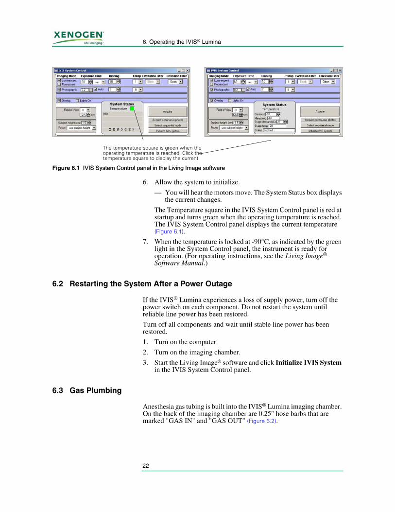
6. Allow the system to initialize.
— You will hear the motors move. The System Status box displays the current changes.
The Temperature square in the IVIS System Control panel is red at startup and turns green when the operating temperature is reached. The IVIS System Control panel displays the current temperature (Figure 6.1).
7. When the temperature is locked at -90°C, as indicated by the green light in the System Control panel, the instrument is ready for operation. (For operating instructions, see the Living Image® Software Manual.)
6.2 Restarting the System After a Power Outage
If the IVIS® Lumina experiences a loss of supply power, turn off the power switch on each component. Do not restart the system until reliable line power has been restored.
Turn off all components and wait until stable line power has been restored.
1. Turn on the computer
2. Turn on the imaging chamber.
3. Start the Living Image® software and click Initialize IVIS System in the IVIS System Control panel.
6.3 Gas Plumbing
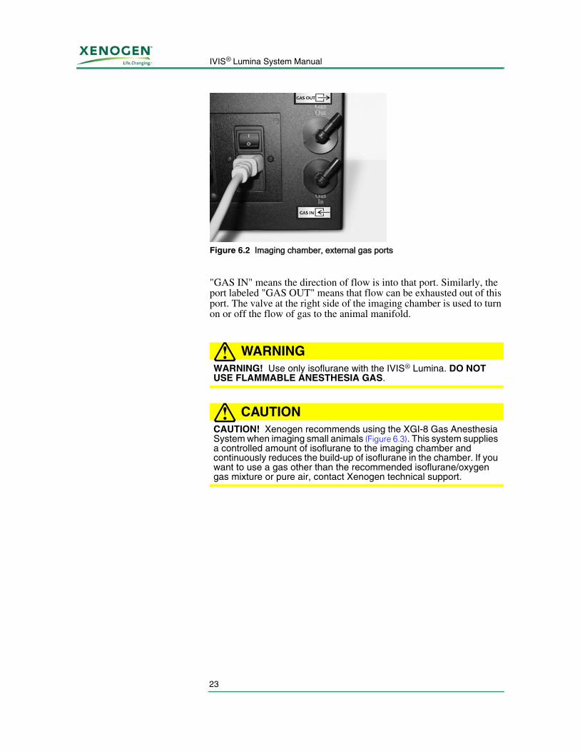
Anesthesia gas tubing is built into the IVIS® Lumina imaging chamber. On the back of the imaging chamber are 0.25" hose barbs that are marked "GAS IN" and "GAS OUT" (Figure 6.2).
Figure 6.1 IVIS System Control panel in the Living Image software
The temperature square is green when the operating temperature is reached. Click the temperature square to display the current
23
IVIS® Lumina System Manual
"GAS IN" means the direction of flow is into that port. Similarly, the port labeled "GAS OUT" means that flow can be exhausted out of this port. The valve at the right side of the imaging chamber is used to turn on or off the flow of gas to the animal manifold.
WARNING!WARNING! Use only isoflurane with the IVIS® Lumina. DO NOT USE FLAMMABLE ANESTHESIA GAS.
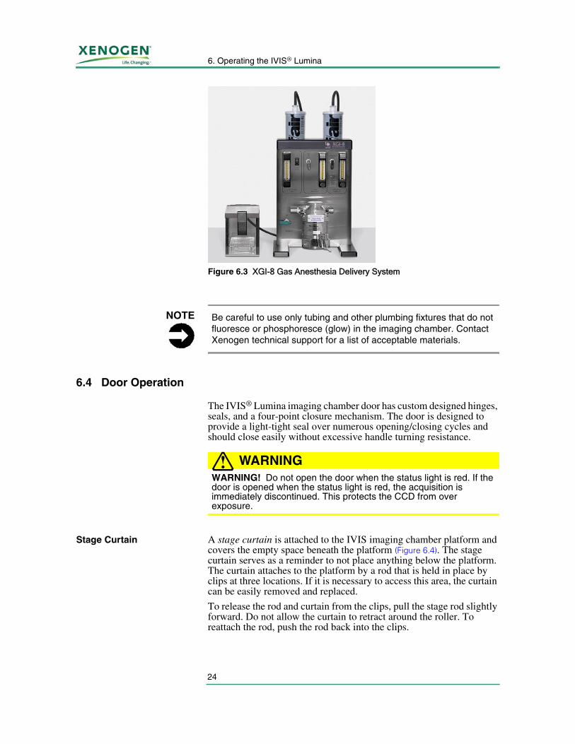
CAUTION!CAUTION! Xenogen recommends using the XGI-8 Gas Anesthesia System when imaging small animals (Figure 6.3). This system supplies a controlled amount of isoflurane to the imaging chamber and continuously reduces the build-up of isoflurane in the chamber. If you want to use a gas other than the recommended isoflurane/oxygen gas mixture or pure air, contact Xenogen technical support.
Figure 6.2 Imaging chamber, external gas ports
6. Operating the IVIS® Lumina
24
6.4 Door Operation
The IVIS® Lumina imaging chamber door has custom designed hinges, seals, and a four-point closure mechanism. The door is designed to provide a light-tight seal over numerous opening/closing cycles and should close easily without excessive handle turning resistance.
WARNING!WARNING! Do not open the door when the status light is red. If the door is opened when the status light is red, the acquisition is immediately discontinued. This protects the CCD from over exposure.
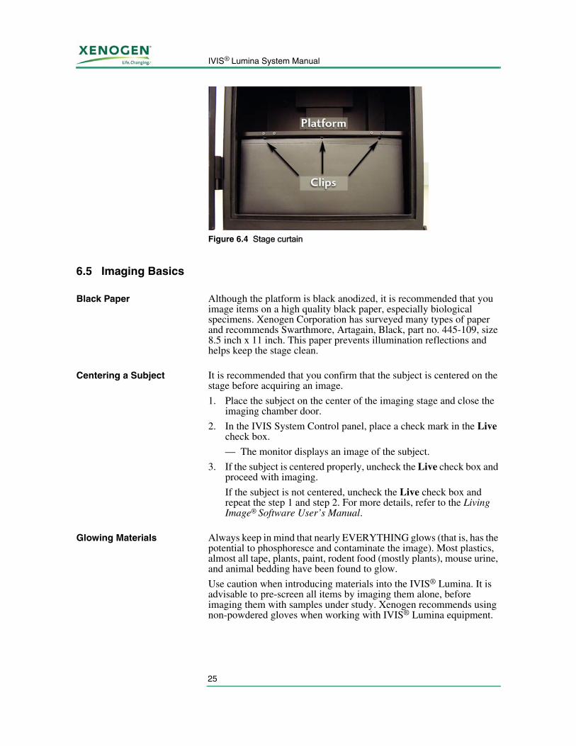
Stage Curtain A stage curtain is attached to the IVIS imaging chamber platform and covers the empty space beneath the platform (Figure 6.4). The stage curtain serves as a reminder to not place anything below the platform. The curtain attaches to the platform by a rod that is held in place by clips at three locations. If it is necessary to access this area, the curtain can be easily removed and replaced.
To release the rod and curtain from the clips, pull the stage rod slightly forward. Do not allow the curtain to retract around the roller. To reattach the rod, push the rod back into the clips.
Figure 6.3 XGI-8 Gas Anesthesia Delivery System
NOTE Be careful to use only tubing and other plumbing fixtures that do not fluoresce or phosphoresce (glow) in the imaging chamber. Contact Xenogen technical support for a list of acceptable materials.
25
IVIS® Lumina System Manual
6.5 Imaging Basics
Black Paper Although the platform is black anodized, it is recommended that you image items on a high quality black paper, especially biological specimens. Xenogen Corporation has surveyed many types of paper and recommends Swarthmore, Artagain, Black, part no. 445-109, size 8.5 inch x 11 inch. This paper prevents illumination reflections and helps keep the stage clean.
Centering a Subject It is recommended that you confirm that the subject is centered on the stage before acquiring an image.
1. Place the subject on the center of the imaging stage and close the imaging chamber door.
2. In the IVIS System Control panel, place a check mark in the Live check box.
— The monitor displays an image of the subject.
3. If the subject is centered properly, uncheck the Live check box and proceed with imaging.
If the subject is not centered, uncheck the Live check box and repeat the step 1 and step 2. For more details, refer to the Living Image® Software User’s Manual.
Glowing Materials Always keep in mind that nearly EVERYTHING glows (that is, has the potential to phosphoresce and contaminate the image). Most plastics, almost all tape, plants, paint, rodent food (mostly plants), mouse urine, and animal bedding have been found to glow.
Use caution when introducing materials into the IVIS® Lumina. It is advisable to pre-screen all items by imaging them alone, before imaging them with samples under study. Xenogen recommends using non-powdered gloves when working with IVIS® Lumina equipment.
Figure 6.4 Stage curtain
6. Operating the IVIS® Lumina
26
6.6 System Shut Down Procedure
Xenogen Corporation does not recommend power cycling the IVIS Lumina (turning the system components on and off). If it is necessary to shut down the imaging system for any reason, it is important to follow the procedure below.
1. Close the Living Image® software and save any information of interest at the prompt.
2. Turn off the IVIS® Lumina imaging chamber.
3. Turn off the computer using the standard Windows® shut down procedure.
If you have any problems during the shut down or start up procedure, please contact Xenogen technical support for assistance.
27
IVIS® Lumina System Manual
7 Care & Maintenance
7.1 Cleaning the IVIS Lumina
Approved Cleaning Solutions
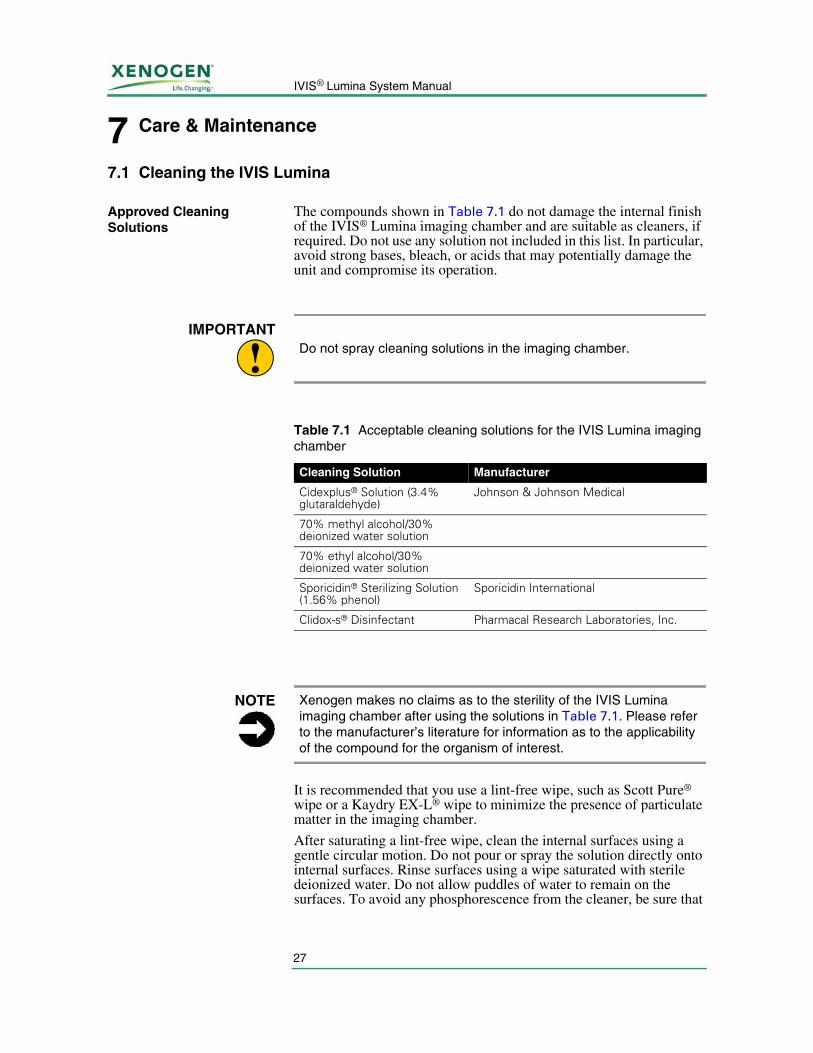
The compounds shown in Table 7.1 do not damage the internal finish of the IVIS® Lumina imaging chamber and are suitable as cleaners, if required. Do not use any solution not included in this list. In particular, avoid strong bases, bleach, or acids that may potentially damage the unit and compromise its operation.
It is recommended that you use a lint-free wipe, such as Scott Pure® wipe or a Kaydry EX-L® wipe to minimize the presence of particulate matter in the imaging chamber.
After saturating a lint-free wipe, clean the internal surfaces using a gentle circular motion. Do not pour or spray the solution directly onto internal surfaces. Rinse surfaces using a wipe saturated with sterile deionized water. Do not allow puddles of water to remain on the surfaces. To avoid any phosphorescence from the cleaner, be sure that
!IMPORTANT
Do not spray cleaning solutions in the imaging chamber.
Table 7.1 Acceptable cleaning solutions for the IVIS Lumina imaging chamber
Cleaning Solution Manufacturer
Cidexplus® Solution (3.4% glutaraldehyde)
Johnson & Johnson Medical
70% methyl alcohol/30% deionized water solution
70% ethyl alcohol/30% deionized water solution
Sporicidin® Sterilizing Solution (1.56% phenol)
Sporicidin International
Clidox-s® Disinfectant Pharmacal Research Laboratories, Inc.
NOTE Xenogen makes no claims as to the sterility of the IVIS Lumina imaging chamber after using the solutions in Table 7.1. Please refer to the manufacturer’s literature for information as to the applicability of the compound for the organism of interest.

7. Care & Maintenance
28
the surfaces are dry before using the imaging chamber. Be careful not to smudge the camera lens and optical filters.
Consider dedicating an IVIS® Lumina for immunodeficient animals to remove the risk of cross contamination.
29
IVIS® Lumina System Manual
8 Troubleshooting
Measured Temperature Does Not Equal the Demand Temperature . . 29Photographic Image Is Unacceptable . . . . . . . . . . . . . . . . . 30Luminescent Image Is Unacceptable . . . . . . . . . . . . . . . . . . 31No Image Is Produced . . . . . . . . . . . . . . . . . . . . . . . . . . 32
8.1 Measured Temperature Does Not Equal the Demand Temperature
At start up, the Living Image® software programs the CCD camera to maintain the CCD at -90° C. If the camera power supply remains on (IVIS® Lumina box), the system maintains this temperature regardless of whether the Living Image software is open or the computer is turned on.
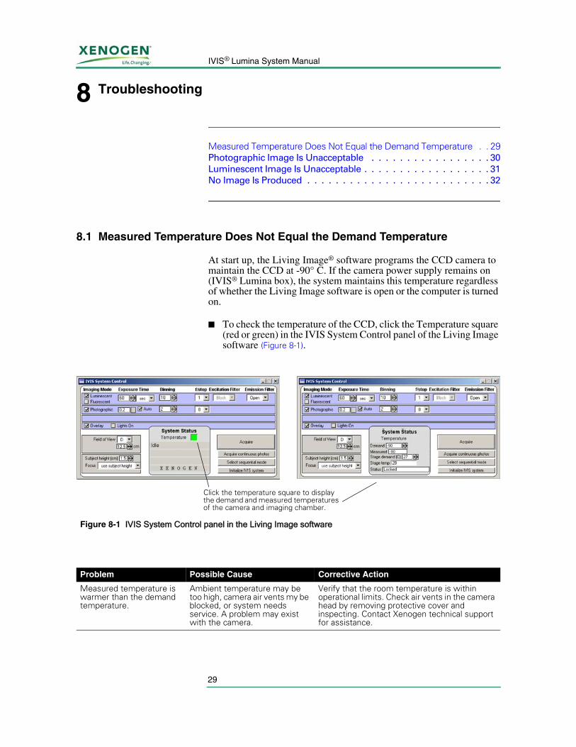
■ To check the temperature of the CCD, click the Temperature square (red or green) in the IVIS System Control panel of the Living Image software (Figure 8-1).
Figure 8-1 IVIS System Control panel in the Living Image software
Click the temperature square to display the demand and measured temperatures of the camera and imaging chamber.
Problem Possible Cause Corrective Action
Measured temperature is warmer than the demand temperature.
Ambient temperature may be too high, camera air vents my be blocked, or system needs service. A problem may exist with the camera.
Verify that the room temperature is within operational limits. Check air vents in the camera head by removing protective cover and inspecting. Contact Xenogen technical support for assistance.
8. Troubleshooting
30
8.2 Photographic Image Is Unacceptable
Photograph imaging parameters are automatically controlled and generally produce a good quality photo. If shiny objects are imaged, creating specular reflections, the automatic algorithm may get confused and produce an underexposed image.
Also, refer to the Living Image Software Manual for further details on acquiring images.
Problem Corrective Action
Something is obstructing the stage.
1. Open the door to the imaging chamber and visually inspect the stage.2. Remove anything that is physically obstructing the stage. If there is no obstruction
and/or the stage still does not move, contact Xenogen technical support for assistance.
Problem Possible Cause Corrective Action
Image is streaked. Subject moved during the exposure.
Check to see if the subject may have moved. If the subject is not on the sample stage, it is probably on the floor of the imaging chamber. If the sample has moved, locate and reanesthetize it. If gas anesthesia is being used, confirm that the anesthesia is turned on and the flow rate is appropriate.
Image is blurry. Subject height is significantly less than or greater than 1.5 cm.
The focus is set for a sample height of 1.5 cm. Significant deviation from this height results in an out-of-focus photograph.
Incorrect f/stop setting. The f/stop for photographs should be set to f/8 or f/16. An f/stop smaller than 8 reduces the depth of field in the photograph.
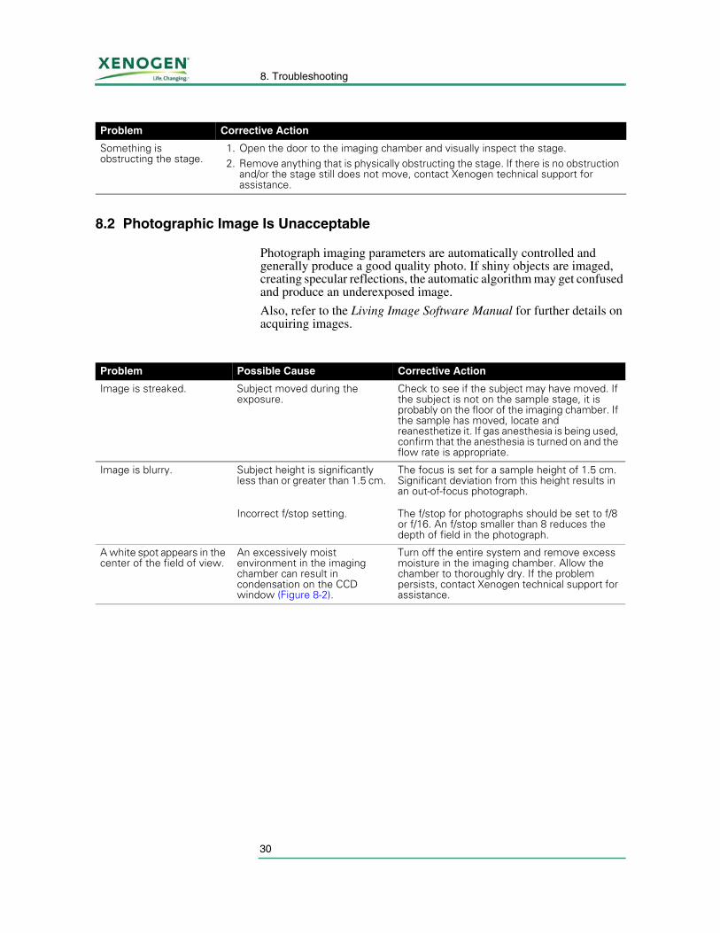
A white spot appears in the center of the field of view.
An excessively moist environment in the imaging chamber can result in condensation on the CCD window (Figure 8-2).
Turn off the entire system and remove excess moisture in the imaging chamber. Allow the chamber to thoroughly dry. If the problem persists, contact Xenogen technical support for assistance.
31
IVIS® Lumina System Manual
8.3 Luminescent Image Is Unacceptable
Binning, f/stop, and exposure time affect the appearance of a luminescent image. Please refer to the Living Image® Software Manual for instructions on setting binning, exposure time, and f/stop values.
In order to function properly and reduce camera noise, the CCD camera must be cooled to the demand temperature before acquiring an image. If the camera is not cooled to the demand temperature, imaging may result in false positive signals.
Figure 8-2 Condensation example
Problem Corrective Action
Light contamination-Internal
Check to see that there are no extraneous light sources in the imaging chamber. Many substances phosphoresce when exposed to light. Be especially cautious of plastics and substances that contain pigment. Be sure to pre-screen any substance or material before performing actual experiments.
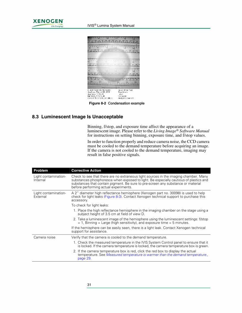
Light contamination-External
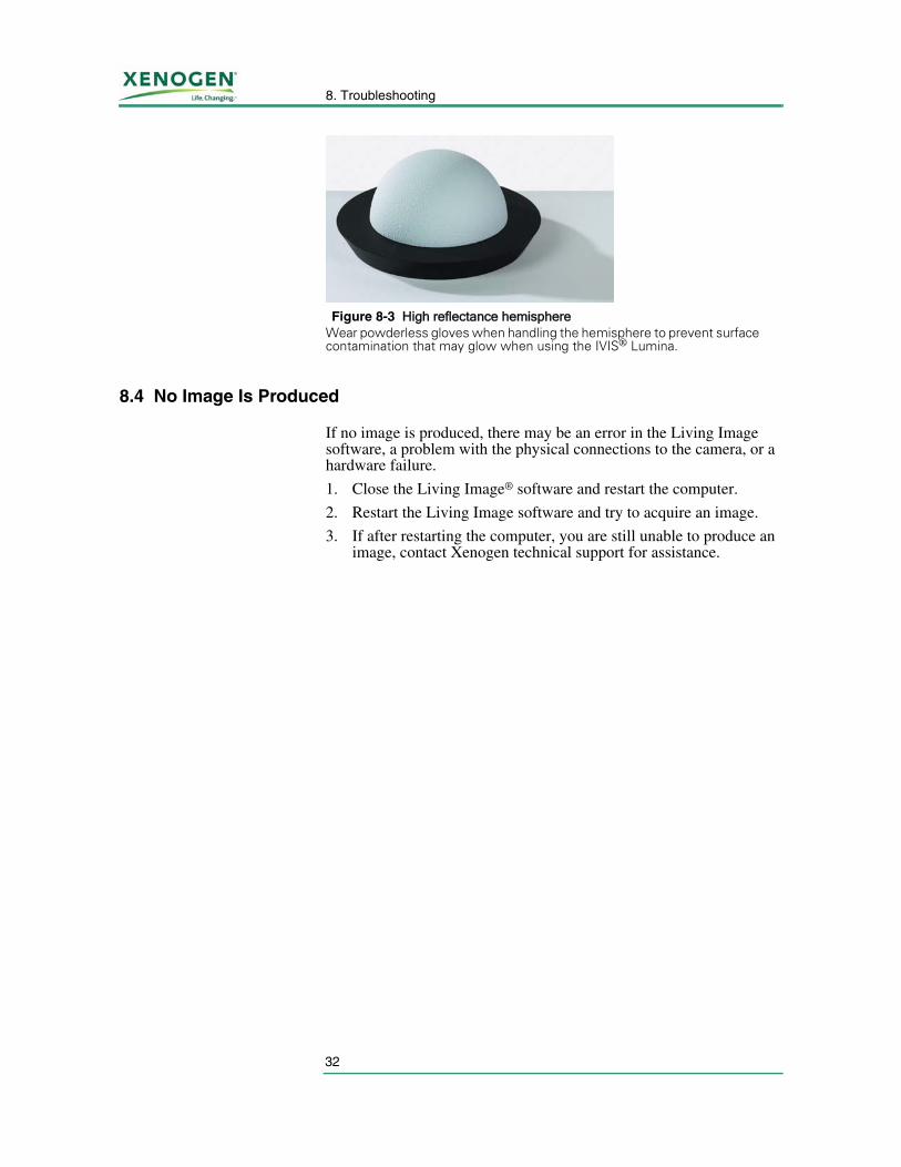
A 2” diameter high reflectance hemisphere (Xenogen part no. 30098) is used to help check for light leaks (Figure 8-3). Contact Xenogen technical support to purchase this accessory.To check for light leaks:1. Place the high reflectance hemisphere in the imaging chamber on the stage using a
subject height of 3.5 cm at field of view D.2. Take a luminescent image of the hemisphere using the luminescent settings: f/stop
= 1, Binning = Large (high sensitivity), and exposure time = 5 minutes.If the hemisphere can be easily seen, there is a light leak. Contact Xenogen technical support for assistance.
Camera noise Verify that the camera is cooled to the demand temperature.1. Check the measured temperature in the IVIS System Control panel to ensure that it
is locked. If the camera temperature is locked, the camera temperature box is green.2. If the camera temperature box is red, click the red box to display the actual
temperature. See Measured temperature is warmer than the demand temperature., page 29.
8. Troubleshooting
32
8.4 No Image Is Produced
If no image is produced, there may be an error in the Living Image software, a problem with the physical connections to the camera, or a hardware failure.
1. Close the Living Image® software and restart the computer.
2. Restart the Living Image software and try to acquire an image.
3. If after restarting the computer, you are still unable to produce an image, contact Xenogen technical support for assistance.
Figure 8-3 High reflectance hemisphereWear powderless gloves when handling the hemisphere to prevent surface contamination that may glow when using the IVIS® Lumina.
33
IVIS® Lumina System Manual
9 XFO-12 Fluorescence Equipment
Installation Requirements . . . . . . . . . . . . . . . . . . . . 34Specifications . . . . . . . . . . . . . . . . . . . . . . . . . . . 34Description and Theory of Operation . . . . . . . . . . . . . . 35Acquiring Fluorescent Images . . . . . . . . . . . . . . . . . . 40Troubleshooting . . . . . . . . . . . . . . . . . . . . . . . . . 42Care and Maintenance of the XFO-12 Fluorescence Equipment 46XFO-12 Hardware Replacement Parts List . . . . . . . . . . . 47
The XFO-12 fluorescence equipment provides the IVIS® Lumina with fluorescent imaging capability. The XFO-12 equipment can be used for in vitro or in vivo applications. The sensitive range of the IVIS Lumina CCD camera sets the wavelength range for fluorescence applications, which is approximately 400-950 nm (30-85% quantum efficiency). As with bioluminescent imaging, wavelengths greater than 600 nm are preferred for in vivo fluorescent applications due to lower absorption in tissue. The Living Image software controls fluorescent image acquisition, including lamp power, level, and filter selection.
This chapter explains how to operate the XFO-12 fluorescence equipment with the IVIS Lumina. It also provides important safety and maintenance information.
You should also be familiar with and refer to the other chapters of this manual for the IVIS Lumina.
For instructions on how to use the Living Image software that controls fluorescent image acquisition, see the Living Image® Software Manual that is provided with the software.
The Schott Fostec DCR® III Direct Current Regulated Light Source User’s Manual and Technical Reference is a separate manual for the light source module. It provides additional useful information on the light source module and its safe operation.
!IMPORTANT To ensure optimum and safe performance of the XFO-12
fluorescence equipment with maximum service life, read this chapter carefully before you use IVIS Lumina with the fluorescence equipment.
9. XFO-12 Fluorescence Equipment
34
9.1 Installation Requirements
The XFO-12 fluorescence equipment requires 100 - 240 VAC electrical power. The system automatically accepts the required voltage.
For more details on the XFO-12 operating requirements, see Specifications, page 34.
9.2 Specifications
Electrical Power and Fuses
Environmental - Temperature and Humidity
Lamp and Fuse
Ventilation Requirements Provide sufficient space (minimum 6 inches) behind the fan of the light source module so that airflow is unobstructed. Provide a similar minimum distance behind the IVIS Lumina to enable fan cooling as well as adequate room for fiber optic cable routing.
Chemicals Required for Operation
No chemicals are required for the operation of the IVIS Lumina or the XFO-12 fluorescence equipment. Other user supplied chemicals or materials may be required for your specific biological testing procedures.
!IMPORTANT The XFO-12 fluorescence equipment operates at the same voltage
as the IVIS® Lumina chamber and must not be used at other than its labeled voltage.
Voltage Available 100VAC, 50/60 Hz - 240VAC, 50/60Hz
Power Consumption 200 W
NOTEFor more on additional electrical power requirements of the IVIS Lumina, see Chapter 5, page 15.
Temperature 15-25° C
Humidity 0% to 80% Non-Condensing
Type of Use Indoor
Lamp 150 W Quartz Tungsten Halogen 21 VEKE lamp life: 400 hrs (“High” setting), 6,000 hrs (“Low” setting)Color temperature 3250 K°
Fuse 3A(10) 250VAC
35
IVIS® Lumina System Manual
Weight and Dimensions of the XFO-12 Fluorescence Light Source Module
9.3 Description and Theory of Operation
System Components The Xenogen XFO-12 fluorescence equipment provides fluorescent imaging capability. You can conveniently switch between bioluminescent and fluorescent imaging applications.
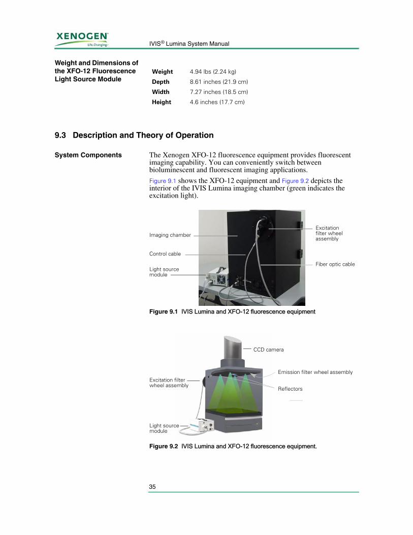
Figure 9.1 shows the XFO-12 equipment and Figure 9.2 depicts the interior of the IVIS Lumina imaging chamber (green indicates the excitation light).
Weight 4.94 lbs (2.24 kg)
Depth 8.61 inches (21.9 cm)
Width 7.27 inches (18.5 cm)
Height 4.6 inches (17.7 cm)
Figure 9.1 IVIS Lumina and XFO-12 fluorescence equipment
Figure 9.2 IVIS Lumina and XFO-12 fluorescence equipment.
Imaging chamberExcitation filter wheel assembly
Fiber optic cable
Control cable
Light source module
Excitation filter wheel assembly
Light source module
Emission filter wheel assembly
Reflectors
CCD camera
9. XFO-12 Fluorescence Equipment
36
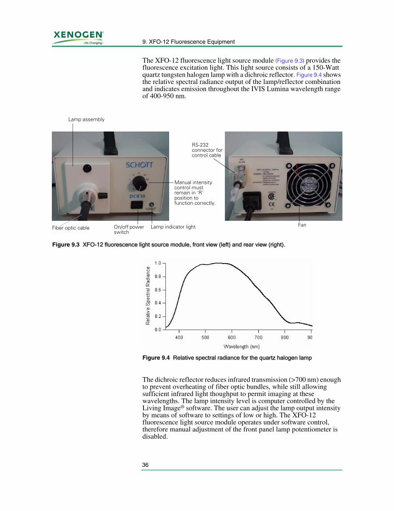
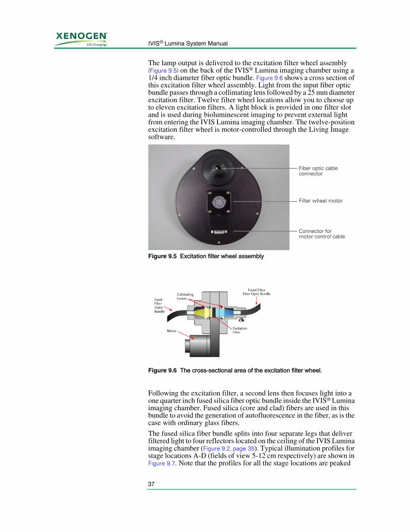
The XFO-12 fluorescence light source module (Figure 9.3) provides the fluorescence excitation light. This light source consists of a 150-Watt quartz tungsten halogen lamp with a dichroic reflector. Figure 9.4 shows the relative spectral radiance output of the lamp/reflector combination and indicates emission throughout the IVIS Lumina wavelength range of 400-950 nm.
The dichroic reflector reduces infrared transmission (>700 nm) enough to prevent overheating of fiber optic bundles, while still allowing sufficient infrared light thoughput to permit imaging at these wavelengths. The lamp intensity level is computer controlled by the Living Image® software. The user can adjust the lamp output intensity by means of software to settings of low or high. The XFO-12 fluorescence light source module operates under software control, therefore manual adjustment of the front panel lamp potentiometer is disabled.
Figure 9.3 XFO-12 fluorescence light source module, front view (left) and rear view (right).
On/off power switch
Lamp assembly
Fiber optic cable
Manual intensity control must remain in 'R' position to function correctly.
Lamp indicator light
RS-232 connector for control cable
Fan
Figure 9.4 Relative spectral radiance for the quartz halogen lamp
37
IVIS® Lumina System Manual
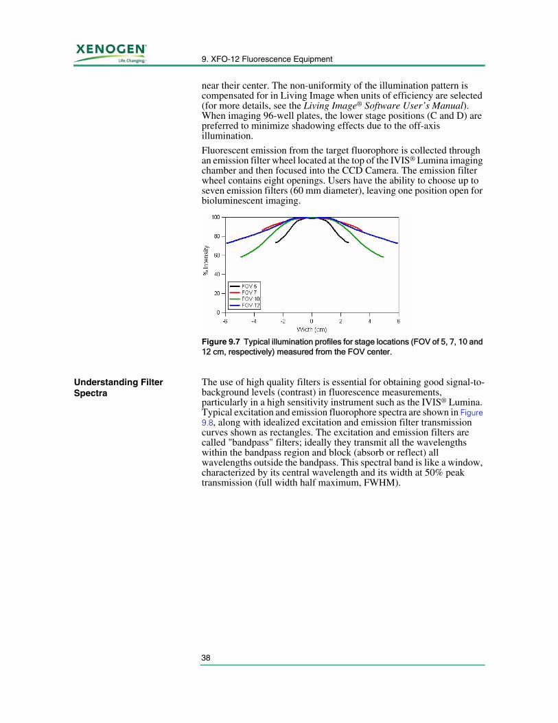
The lamp output is delivered to the excitation filter wheel assembly (Figure 9.5) on the back of the IVIS® Lumina imaging chamber using a 1/4 inch diameter fiber optic bundle. Figure 9.6 shows a cross section of this excitation filter wheel assembly. Light from the input fiber optic bundle passes through a collimating lens followed by a 25 mm diameter excitation filter. Twelve filter wheel locations allow you to choose up to eleven excitation filters. A light block is provided in one filter slot and is used during bioluminescent imaging to prevent external light from entering the IVIS Lumina imaging chamber. The twelve-position excitation filter wheel is motor-controlled through the Living Image software.
Following the excitation filter, a second lens then focuses light into a one quarter inch fused silica fiber optic bundle inside the IVIS® Lumina imaging chamber. Fused silica (core and clad) fibers are used in this bundle to avoid the generation of autofluorescence in the fiber, as is the case with ordinary glass fibers.
The fused silica fiber bundle splits into four separate legs that deliver filtered light to four reflectors located on the ceiling of the IVIS Lumina imaging chamber (Figure 9.2, page 35). Typical illumination profiles for stage locations A-D (fields of view 5-12 cm respectively) are shown in Figure 9.7. Note that the profiles for all the stage locations are peaked
Figure 9.5 Excitation filter wheel assembly
Figure 9.6 The cross-sectional area of the excitation filter wheel.
Fiber optic cable connector
Filter wheel motor
Connector for motor control cable
9. XFO-12 Fluorescence Equipment
38
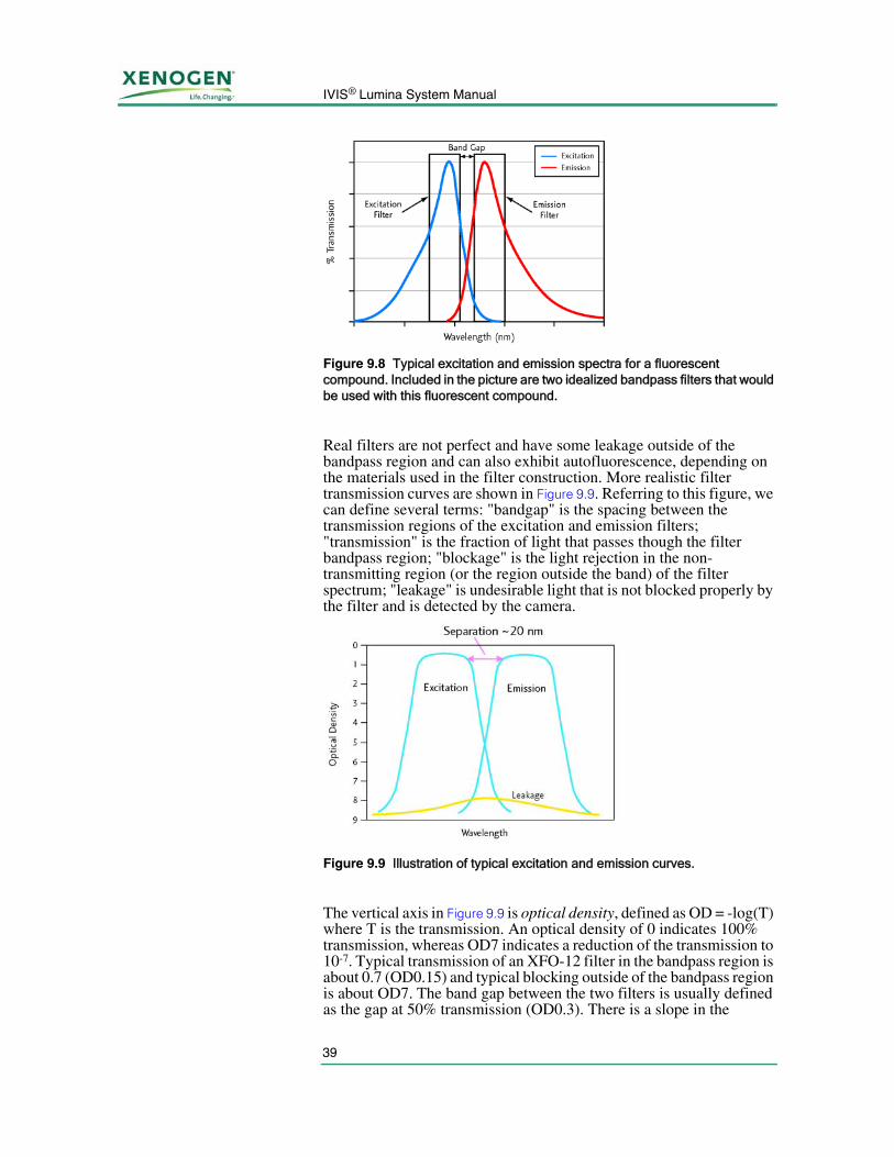
near their center. The non-uniformity of the illumination pattern is compensated for in Living Image when units of efficiency are selected (for more details, see the Living Image® Software User’s Manual). When imaging 96-well plates, the lower stage positions (C and D) are preferred to minimize shadowing effects due to the off-axis illumination.
Fluorescent emission from the target fluorophore is collected through an emission filter wheel located at the top of the IVIS® Lumina imaging chamber and then focused into the CCD Camera. The emission filter wheel contains eight openings. Users have the ability to choose up to seven emission filters (60 mm diameter), leaving one position open for bioluminescent imaging.
Understanding Filter Spectra
The use of high quality filters is essential for obtaining good signal-to-background levels (contrast) in fluorescence measurements, particularly in a high sensitivity instrument such as the IVIS® Lumina. Typical excitation and emission fluorophore spectra are shown in Figure 9.8, along with idealized excitation and emission filter transmission curves shown as rectangles. The excitation and emission filters are called "bandpass" filters; ideally they transmit all the wavelengths within the bandpass region and block (absorb or reflect) all wavelengths outside the bandpass. This spectral band is like a window, characterized by its central wavelength and its width at 50% peak transmission (full width half maximum, FWHM).
Figure 9.7 Typical illumination profiles for stage locations (FOV of 5, 7, 10 and 12 cm, respectively) measured from the FOV center.
39
IVIS® Lumina System Manual
Real filters are not perfect and have some leakage outside of the bandpass region and can also exhibit autofluorescence, depending on the materials used in the filter construction. More realistic filter transmission curves are shown in Figure 9.9. Referring to this figure, we can define several terms: "bandgap" is the spacing between the transmission regions of the excitation and emission filters; "transmission" is the fraction of light that passes though the filter bandpass region; "blockage" is the light rejection in the non-transmitting region (or the region outside the band) of the filter spectrum; "leakage" is undesirable light that is not blocked properly by the filter and is detected by the camera.
The vertical axis in Figure 9.9 is optical density, defined as OD = -log(T) where T is the transmission. An optical density of 0 indicates 100% transmission, whereas OD7 indicates a reduction of the transmission to 10-7. Typical transmission of an XFO-12 filter in the bandpass region is about 0.7 (OD0.15) and typical blocking outside of the bandpass region is about OD7. The band gap between the two filters is usually defined as the gap at 50% transmission (OD0.3). There is a slope in the
Figure 9.8 Typical excitation and emission spectra for a fluorescent compound. Included in the picture are two idealized bandpass filters that would be used with this fluorescent compound.
Figure 9.9 Illustration of typical excitation and emission curves.
9. XFO-12 Fluorescence Equipment
40
transition region from bandpass to blocking, as indicated in Figure 9.9. A steep slope is required to avoid overlap between the two filters.
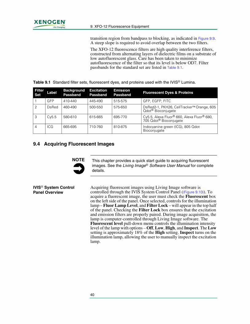
The XFO-12 fluorescence filters are high quality interference filters, constructed from alternating layers of dielectric films on a substrate of low autofluorescent glass. Care has been taken to minimize autofluorescence of the filter so that its level is below OD7. Filter passbands for the standard set are listed in Table 9.1.
9.4 Acquiring Fluorescent Images
IVIS® System Control Panel Overview
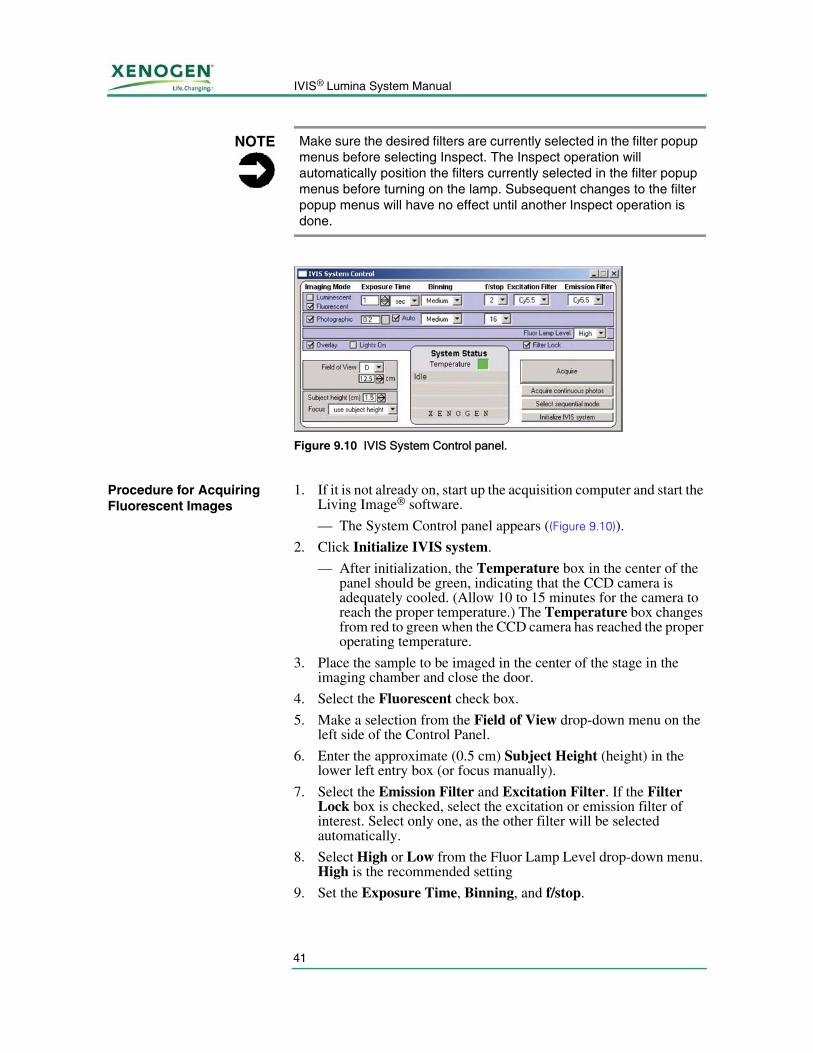
Acquiring fluorescent images using Living Image software is controlled through the IVIS System Control Panel ((Figure 9.10)). To acquire a fluorescent image, the user must check the Fluorescent box on the left side of the panel. Once selected, controls for the illumination lamp – Fluor Lamp Level, and Filter Lock – will appear in the top half of the panel. Checking the Filter Lock box ensures that the excitation and emission filters are properly paired. During image acquisition, the lamp is computer-controlled through Living Image software. The Fluorescent level pull-down menu controls the illumination intensity level of the lamp with options – Off, Low, High, and Inspect. The Low setting is approximately 18% of the High setting. Inspect turns on the illumination lamp, allowing the user to manually inspect the excitation lamp.
Table 9.1 Standard filter sets, fluorescent dyes, and proteins used with the IVIS® Lumina.
Filter Set
LabelBackground Passband
Excitation Passband
Emission Passband
Fluorescent Dyes & Proteins
1 GFP 410-440 445-490 515-575 GFP, EGFP, FITC
2 DsRed 460-490 500-550 575-650 DsRed2-1, PKH26, CellTracker™ Orange, 605 Qdot® Bioconjugate
3 Cy5.5 580-610 615-665 695-770 Cy5.5, Alexa Fluor® 660, Alexa Fluor® 680, 705 Qdot® Bioconjugate
4 ICG 665-695 710-760 810-875 Indocyanine green (ICG), 805 Qdot Bioconjugate
NOTE This chapter provides a quick start guide to acquiring fluorescent images. See the Living Image® Software User Manual for complete details.
41
IVIS® Lumina System Manual
Procedure for Acquiring Fluorescent Images
1. If it is not already on, start up the acquisition computer and start the Living Image® software.
— The System Control panel appears ((Figure 9.10)).
2. Click Initialize IVIS system.
— After initialization, the Temperature box in the center of the panel should be green, indicating that the CCD camera is adequately cooled. (Allow 10 to 15 minutes for the camera to reach the proper temperature.) The Temperature box changes from red to green when the CCD camera has reached the proper operating temperature.
3. Place the sample to be imaged in the center of the stage in the imaging chamber and close the door.
4. Select the Fluorescent check box.
5. Make a selection from the Field of View drop-down menu on the left side of the Control Panel.
6. Enter the approximate (0.5 cm) Subject Height (height) in the lower left entry box (or focus manually).
7. Select the Emission Filter and Excitation Filter. If the Filter Lock box is checked, select the excitation or emission filter of interest. Select only one, as the other filter will be selected automatically.
8. Select High or Low from the Fluor Lamp Level drop-down menu. High is the recommended setting
9. Set the Exposure Time, Binning, and f/stop.
NOTE Make sure the desired filters are currently selected in the filter popup menus before selecting Inspect. The Inspect operation will automatically position the filters currently selected in the filter popup menus before turning on the lamp. Subsequent changes to the filter popup menus will have no effect until another Inspect operation is done.
Figure 9.10 IVIS System Control panel.
9. XFO-12 Fluorescence Equipment
42
Fluorescence is generally brighter than bioluminescence, so the exposure time is shorter and f/stop higher (smaller lens opening). Typical fluorescent image camera settings might be 10 sec exposure time, Binning=small, and f/2.
10. Click Acquire.
— After the exposure is completed, the overlay image is displayed.
11. To save the data, select Living Image ➞Save Living Image Data from the main menu bar.
This completes the data acquisition. To obtain additional images, repeat the process, beginning with step 3.
The Image image window that displays the fluorescent image includes annotations specific to fluorescence (including emission filter, excitation filter, and fluorescence level) as well as standard annotations such as exposure time, f/stop, FOV, and date/time of exposure.
9.5 Troubleshooting
Hardware Problems If you have difficulty during fluorescent imaging, the trouble may be due to the lack of excitation light. Loss of excitation light can result from either a burned out quartz tungsten halogen lamb or a blown line fuse. The following procedure describes a troubleshooting process for determining the problem. Figure 9.3, page 36 shows the XFO-12 fluorescence light source module.)
1. Verify that the fiber optic cables are not loosened or disconnected from their proper connectors.
2. Adjust "Fluor Light Level" (excitation lamp) to a value of high in the IVIS System Control Panel.
3. Check the “Change Lamp When Red” indicator on the front of the light source module. If indicator is red, proceed to Lamp Replacement, page 44.
4. Take a fluorescent image and check for light and fan operation by looking through the fan guard on the rear panel of the light source module. If there is neither, a blown fuse is the probable cause for light loss. See Fuse Replacement below.
5. Observe the operation of the system by selecting "Inspect" in the Fluorescent Lamp Level drop down list. This causes the selected filter to move into place and the lamp to turn on. Open the chamber and visually inspect to see if the excitation light is incident on the sample stage.
NOTE During the fluorescent image acquisition, the Acquire button becomes a Stop button, which can be used to terminate the exposure, if necessary.
43
IVIS® Lumina System Manual
WARNING!WARNING! DO NOT disconnect or reattach the electrical control cable that connects the XFO-12 fluorescence equipment (excitation filter assembly) to the light source module and IVIS® Lumina (electronics tray) when the power is on. See System Components, page 35, Figure 9.1 and Figure 9.2 for photographs of these components. Disconnecting or reconnecting the control cable when the system has electrical power will damage the system. Always turn off the front panel light source module switch and the rear-mounted ON/OFF switch on the IVIS Lumina before making or breaking any of these cable connections.
Fuse Replacement
WARNING!WARNING! The following procedure can expose the user to hazardous voltages unless the electrical power to the XFO-12 fluorescence light source module is completely eliminated. As instructed in the procedure, turn off the lamp from the module front panel ON/OFF switch and remove the electrical power to the module by disconnecting the plug from the surge protector and the back of the module.
1. See the Fuse Replacement section in the separate manual for the light source module (SCHOTT Fostec DCR® III Direct Current Regulated Light Source User’s Manual and Technical Reference).
2. Press the ON(1)/OFF(0) switch to the OFF(0) position on the light source module.
3. Remove AC line cord from the AC power receptacle on the surge protector.
4. Remove the AC line cord from the power entry module on the rear panel of the light source module.
5. Pull out the fuse drawer. The fuse drawer is part of the power entry module, and is located directly beneath where the AC line cord plugs in. Use a thin bladed screwdriver or penknife blade if necessary. Use care not to damage the drawer. Remove the blown fuse that is positioned closest to the light source module. The second fuse in front of the holder is a spare. Discard the blown fuse.
6. Examine the spare fuse and verify it is the correct rating. See Electrical Power and Fuses, page 34.
7. Place the replacement fuse into the fuse drawer. The fuse will work in either direction. Fill the spares slot in the drawer holder if another good fuse of correct rating is available. Fuse value: 3.0A, 5 x 20, 250V (Xenogen part no. 20395).
8. Push the fuse drawer until it clicks into position.
9. Reattach the AC line cord to the power entry module, then to the AC receptacle on the surge protector.
10. Return the ON/OFF switch to the ON(1) position (the red indicator will be visible on the switch).
9. XFO-12 Fluorescence Equipment
44
11. Resume normal operation.
Lamp Replacement
WARNING!WARNING! The following procedure can expose the user to hazardous voltages unless the electrical power to the light source module of the XFO-12 fluorescence equipment is completely eliminated. As instructed in the procedure, turn off the lamp from the module front panel ON/OFF switch, and remove the electrical power to the module by disconnecting the plug from the surge protector and the back of the module.
WARNING!WARNING! Before you replace the tungsten halogen lamp or lamp assembly in the XFO-12 fluorescence light source module, verify that the lamp and socket are cool before proceeding.
1. Review the sections Lamp Module Replacement and Lamp Replacement in the separate manual for the XFO-12 fluorescence light source module (SCHOTT Fostec DCR® III Direct Current Regulated Light Source User’s Manual and Technical Reference). It contains additional useful information and warnings regarding the light source.
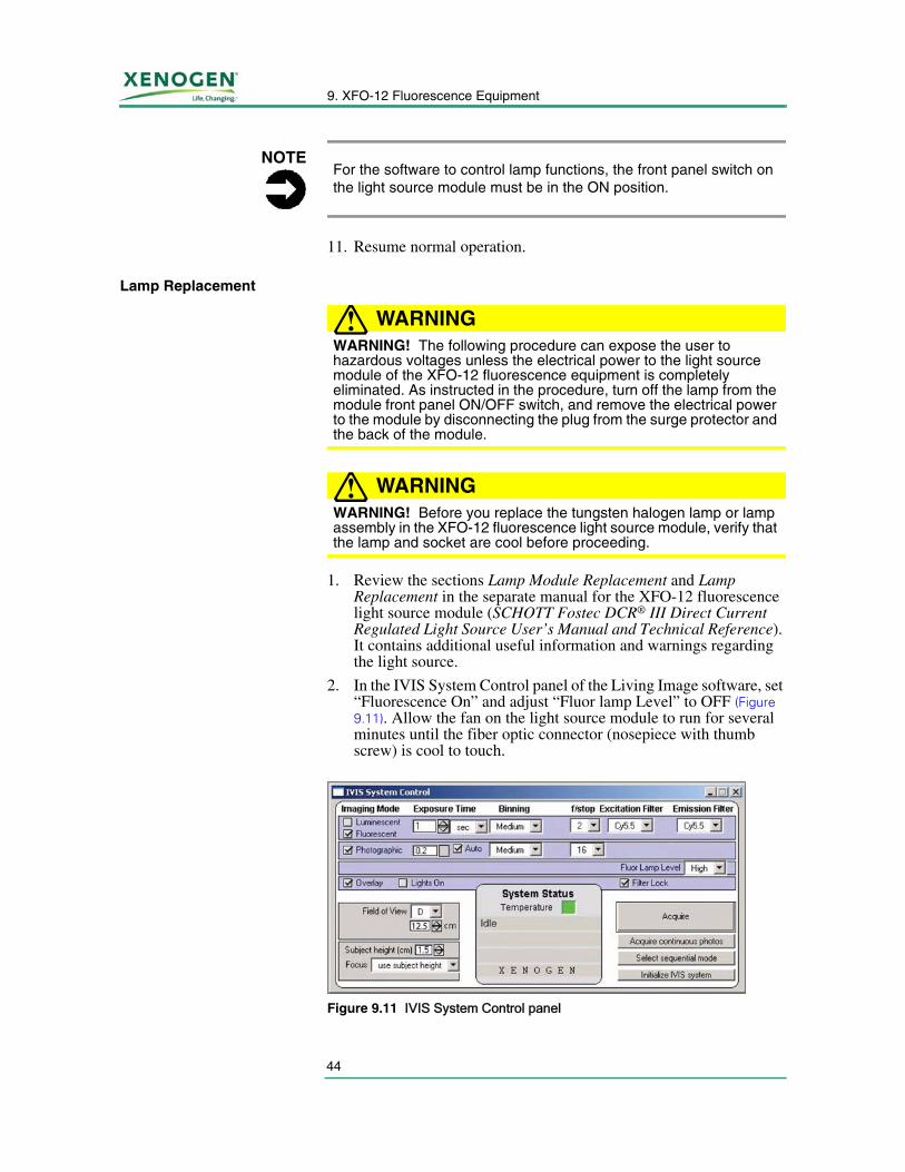
2. In the IVIS System Control panel of the Living Image software, set “Fluorescence On” and adjust “Fluor lamp Level” to OFF (Figure 9.11). Allow the fan on the light source module to run for several minutes until the fiber optic connector (nosepiece with thumb screw) is cool to touch.
NOTEFor the software to control lamp functions, the front panel switch on the light source module must be in the ON position.
Figure 9.11 IVIS System Control panel
45
IVIS® Lumina System Manual
3. Press the ON (1)/OFF(0) switch to the OFF(0) position on the light source module.
4. Remove AC line cord from the AC power receptacle on the surge protector and from the back of the module.
5. Release the lamp assembly from the front panel of the light source module by turning the retaining screw counterclockwise using a straight blade screwdriver. The retaining screw will be disengaged from the front panel, but will remain in place in the lamp assembly.
6. Remove the lamp assembly from the light source module by slowly pulling outward.
7. Check the lamp assembly to verify that the lamp and socket are cool before proceeding.
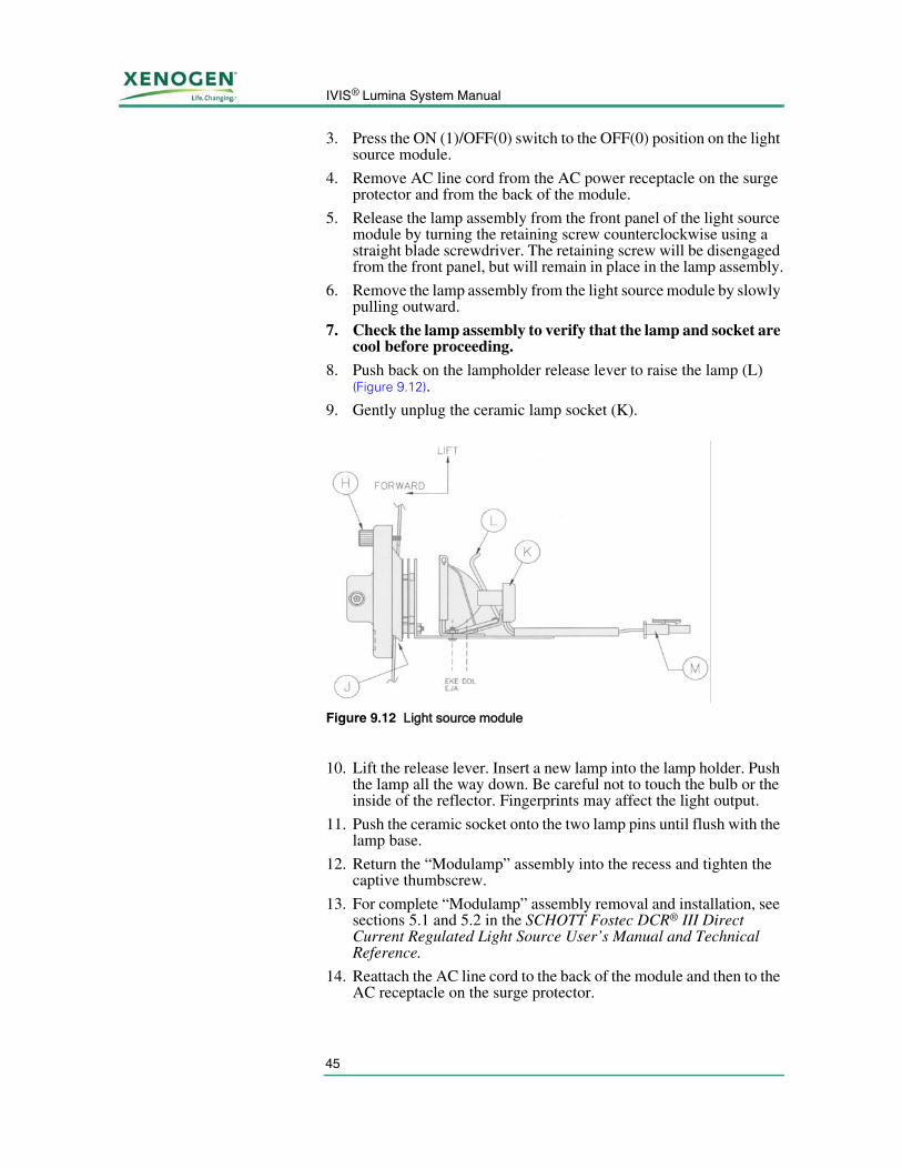
8. Push back on the lampholder release lever to raise the lamp (L) (Figure 9.12).
9. Gently unplug the ceramic lamp socket (K).
10. Lift the release lever. Insert a new lamp into the lamp holder. Push the lamp all the way down. Be careful not to touch the bulb or the inside of the reflector. Fingerprints may affect the light output.
11. Push the ceramic socket onto the two lamp pins until flush with the lamp base.
12. Return the “Modulamp” assembly into the recess and tighten the captive thumbscrew.
13. For complete “Modulamp” assembly removal and installation, see sections 5.1 and 5.2 in the SCHOTT Fostec DCR® III Direct Current Regulated Light Source User’s Manual and Technical Reference.
14. Reattach the AC line cord to the back of the module and then to the AC receptacle on the surge protector.
Figure 9.12 Light source module
9. XFO-12 Fluorescence Equipment
46
15. Return the ON/OFF switch to the ON(1) position (the red indicator will be visible on the switch).
16. Resume normal operation.
9.6 Care and Maintenance of the XFO-12 Fluorescence Equipment
Cleaning the XFO-12 Fluorescence Light Source Module
If necessary, wipe the exterior surfaces of the XFO-12 light source module with a soft cloth.
WARNING!WARNING! DO NOT use fluids to clean the exterior (or interior) of the module. Do not allow fluids of any kind to enter the light source module under any circumstances. Sprays and liquids that come into contact with the light source module or the IVIS® Lumina may result in damage to the system or electrocution.
If the XFO-12 fluorescence light source module requires more aggressive cleaning or sterilization, contact Xenogen technical support.
Cleaning the IVIS Lumina and Other Components of the XFO-12 Fluorescence Equipment
WARNING!WARNING! DO NOT use fluids or moistened towels to clean the any part of the IVIS Lumina where electrical or fiber optic cables make connections. Do not use fluids of any kind in the vicinity of the XFO-12 Excitation Filter Wheel Assembly (mounted on the rear of the imaging chamber). Turn off electrical power to the IVIS Lumina before engaging in cleaning operations using fluids. The Imaging Chamber power switch is located in the rear on the electronics tray.
For more details on how to clean the imaging chamber, see Cleaning the IVIS Lumina, page 27.
Cleaning the Optical Components and Filter Replacement
Contact Xenogen technical support for information about cleaning or sterilizing any of the optical components or the optical filter replacement.
NOTEFor the software to control lamp functions, the front panel switch located on the light source module must be in the “On” position.
47
IVIS® Lumina System Manual
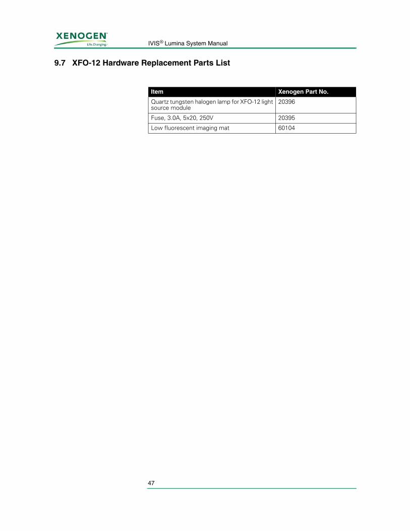
9.7 XFO-12 Hardware Replacement Parts List
Item Xenogen Part No.
Quartz tungsten halogen lamp for XFO-12 light source module
20396
Fuse, 3.0A, 5x20, 250V 20395
Low fluorescent imaging mat 60104

9. XFO-12 Fluorescence Equipment
48
[This page intentionally left blank.]
49
IVIS® Lumina System Manual
Appendix A: Moving IVIS® Lumina With the XWS-260 Workstation
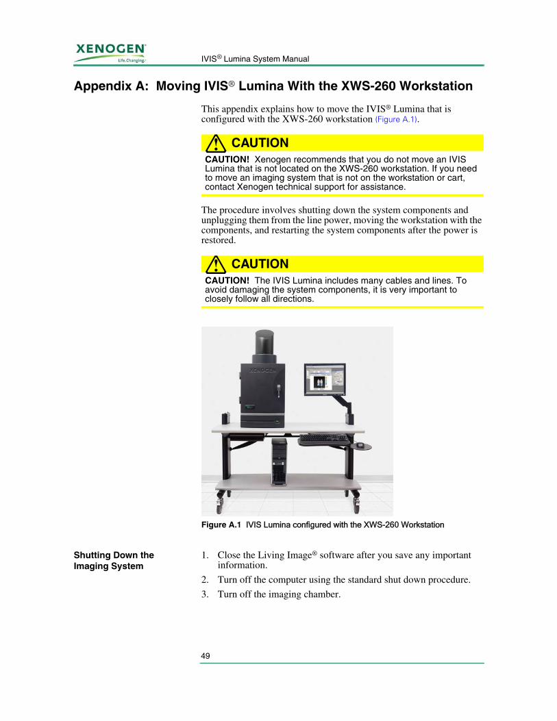
This appendix explains how to move the IVIS® Lumina that is configured with the XWS-260 workstation (Figure A.1).
CAUTION!CAUTION! Xenogen recommends that you do not move an IVIS Lumina that is not located on the XWS-260 workstation. If you need to move an imaging system that is not on the workstation or cart, contact Xenogen technical support for assistance.
The procedure involves shutting down the system components and unplugging them from the line power, moving the workstation with the components, and restarting the system components after the power is restored.
CAUTION!CAUTION! The IVIS Lumina includes many cables and lines. To avoid damaging the system components, it is very important to closely follow all directions.
Shutting Down the Imaging System
1. Close the Living Image® software after you save any important information.
2. Turn off the computer using the standard shut down procedure.
3. Turn off the imaging chamber.
Figure A.1 IVIS Lumina configured with the XWS-260 Workstation
A. Moving IVIS® Lumina With the XWS-260 Workstation
50
Moving the Imaging System on the XWS-260 Workstation
1. Unlock the wheels on the XWS-260 workstation and carefully roll the workstation to the new location.
CAUTION!CAUTION! When moving the imaging system on the XWS-260 workstation, be sure to grasp and push the workstation from as low as comfortably possible. Xenogen advises having two people present during any major move to minimize the risk of damage to the imaging system. If the IVIS® Lumina is damaged during movement, Xenogen cannot be held responsible.
2. When you are finished moving the workstation, lock the wheels.
If you moved the imaging system to a new location, verify that the power outlets meet the power requirements for the system. For more details on equipment power requirements, see Chapter 5, page 15.
Starting the Imaging System
1. Turn on the computer and monitor.
2. Turn on the imaging chamber (the power switch is on the back of the unit).
3. After the desktop screen appears on the monitor, start the Living Image® software.
4. When prompted, enter a user ID (up to three letters) and click Done.
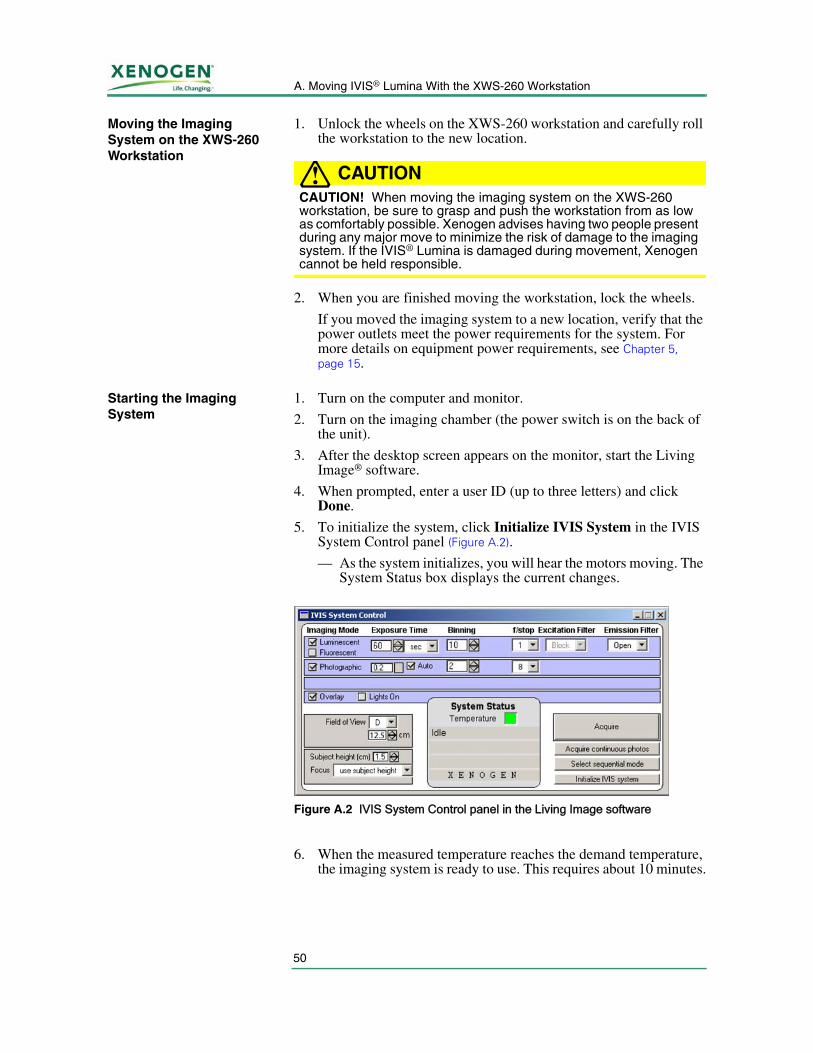
5. To initialize the system, click Initialize IVIS System in the IVIS System Control panel (Figure A.2).
— As the system initializes, you will hear the motors moving. The System Status box displays the current changes.
6. When the measured temperature reaches the demand temperature, the imaging system is ready to use. This requires about 10 minutes.
Figure A.2 IVIS System Control panel in the Living Image software
51
IVIS® Lumina System Manual
Index
Aacquiring fluorescent images 41–42anesthesia delivery system 23
Bbandgap 39bandpass filter 38black paper 25blockage 39
Ccamera noise 31caution definition 3CCD camera 16centering a subject 25chemical & biological safety 9cleaning
imaging system 5cleaning solutions 27cleaning the system 27–28computer 18
specifications 18computer monitor
specifications 19cover 9
Ddefinitions
caution 3voltage 3warning 3
door operation 24
Eelectrical power 34electrical safety 7emission bandpass 40emission filter transmission curve 38emission filter wheel 38emission fluorophore spectra 38environmental considerations
heat 4
water and moisture 5environmental requirements 19excitation filter 40excitation filter transmission curve 38excitation filter wheel 37excitation fluorophore spectra 38eye and burn hazard 8
Ffilter lock 40filter replacement 46filter spectra 38fluorescent dyes 40fluorescent images
acquiring 41–42fluorescent proteins 40fuse 34, 47fuse replacement 43–44
Ggas plumbing 22glowing materials 25
Hhardware problems 42heat safety 4humidity 34
Iimaging chamber 16–17
door 24gas plumbing 22specifications 17stage curtain 24
imaging systemcleaning 5servicing 6
installation requirements 34isoflurane gas anesthesia 23IVIS System Control panel 40
Index
52
Llamp 34lamp replacement 44–46leakage 39light block 37Light Source Module 36
dimensions 35weight 35
lightning 6limited warranty 11–12Living Image software 37low fluorescent imaging mat 47luminescent image unacceptable 31
Mmanual information 4mechanical safety 8modules 9moving the system 49–50
Nno image produced 32
Ooptical density 39optical filter wheel 18other equipment 6
Ppanels 9patents 12photographic image unacceptable 30power cord 6power line surges 6power outage
restarting the system 22power outages 6power overloading 6power sources 5
Rreplace
filter 46fuse 43–44
lamp 44–46replacement parts
fuse 47low fluorescent imaging mat 47quartz tungsten halogen lamp 47
requirementsinstallation 34voltage 34
restarting after power outage 22
Ssafety
chemical & biological 9electrical 7electrical safety 7eye and burn hazard 8mechanical 8panels, cover, and modules 9
safety instructions 3–6servicing 6servicing the equipment 7shut down procedure 26specifications
computer 18computer monitor 19electrical power 34environmental 34fuse 34humidity 34imaging chamber 17lamp 34temperature 34
stage curtain 24start up 21–22startup
restarting after power outage 22subject placement 25system
cleaning 27–28environmental requirements 19moving with XWS-260 workstation 49–50restarting after power outage 22shut down 26start up 21–22
system componentsXFO-12 35
53
IVIS® Lumina System Manual
Ttechnical support 2temperature 34
measured unequal to demand 29trademarks 13transmission 39troubleshooting
camera noise 31measured and demand unequal 29no image produced 32unacceptable luminescent image 31unacceptable photographic image 30
Vventilation requirements 34voltage definition 3voltage requirements 34
Wwarning definition 3water and moisture safety 5
XXenogen technical support 2XFO-12 fluorescence equipment
installation requirements 34system components 35
XWS-260 workstation 49–50

Index
54
[This page intentionally left blank.]