Embed Size (px)
Citation preview
INTERNATIONAL TELECOMMUNICATION UNION
ITU-T H.234TELECOMMUNICATION STANDARDIZATION SECTOR OF ITU
(11/2002)
SERIES H: AUDIOVISUAL AND MULTIMEDIA SYSTEMSInfrastructure of audiovisual services – Systems aspects
Encryption key management and authentication system for audiovisual services
ITU-T Recommendation H.234
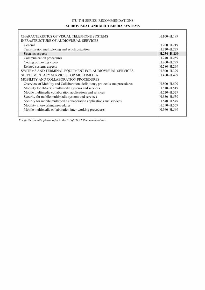
ITU-T H-SERIES RECOMMENDATIONS AUDIOVISUAL AND MULTIMEDIA SYSTEMS
CHARACTERISTICS OF VISUAL TELEPHONE SYSTEMS H.100–H.199 INFRASTRUCTURE OF AUDIOVISUAL SERVICES
General H.200–H.219 Transmission multiplexing and synchronization H.220–H.229 Systems aspects H.230–H.239 Communication procedures H.240–H.259 Coding of moving video H.260–H.279 Related systems aspects H.280–H.299
SYSTEMS AND TERMINAL EQUIPMENT FOR AUDIOVISUAL SERVICES H.300–H.399 SUPPLEMENTARY SERVICES FOR MULTIMEDIA H.450–H.499 MOBILITY AND COLLABORATION PROCEDURES
Overview of Mobility and Collaboration, definitions, protocols and procedures H.500–H.509 Mobility for H-Series multimedia systems and services H.510–H.519 Mobile multimedia collaboration applications and services H.520–H.529 Security for mobile multimedia systems and services H.530–H.539 Security for mobile multimedia collaboration applications and services H.540–H.549 Mobility interworking procedures H.550–H.559 Mobile multimedia collaboration inter-working procedures H.560–H.569
For further details, please refer to the list of ITU-T Recommendations.
ITU-T Rec. H.234 (11/2002) i
ITU-T Recommendation H.234
Encryption key management and authentication system for audiovisual services
Summary This Recommendation describes three methods of encryption key management, namely: – ISO 8732; – Diffie-Hellman; and – RSA.
They are applicable to the encryption of audiovisual signals transmitted digitally using the H.221 frame structure. The management messages defined here are transmitted within the H.221 Encryption Control Signal (ECS) channel, whose structure and use are defined in ITU-T Rec. H.233.
This revision of the Recommendation improves the overall readability of the text, removes ambiguities of certain aspects related to the exchange of asymmetric length of keys, and removes references to MLP encryption according to T.120-series Recommendations, since this effort is for further study. References to ASN.1 were also updated to the newest version of its specification.
Source ITU-T Recommendation H.234 was revised by ITU-T Study Group 16 (2001-2004) and approved under the WTSA Resolution 1 procedure on 29 November 2002.
ii ITU-T Rec. H.234 (11/2002)
FOREWORD
The International Telecommunication Union (ITU) is the United Nations specialized agency in the field of telecommunications. The ITU Telecommunication Standardization Sector (ITU-T) is a permanent organ of ITU. ITU-T is responsible for studying technical, operating and tariff questions and issuing Recommendations on them with a view to standardizing telecommunications on a worldwide basis.
The World Telecommunication Standardization Assembly (WTSA), which meets every four years, establishes the topics for study by the ITU-T study groups which, in turn, produce Recommendations on these topics.
The approval of ITU-T Recommendations is covered by the procedure laid down in WTSA Resolution 1.
In some areas of information technology which fall within ITU-T's purview, the necessary standards are prepared on a collaborative basis with ISO and IEC.
NOTE
In this Recommendation, the expression "Administration" is used for conciseness to indicate both a telecommunication administration and a recognized operating agency.
INTELLECTUAL PROPERTY RIGHTS
ITU draws attention to the possibility that the practice or implementation of this Recommendation may involve the use of a claimed Intellectual Property Right. ITU takes no position concerning the evidence, validity or applicability of claimed Intellectual Property Rights, whether asserted by ITU members or others outside of the Recommendation development process.
As of the date of approval of this Recommendation, ITU had received notice of intellectual property, protected by patents, which may be required to implement this Recommendation. However, implementors are cautioned that this may not represent the latest information and are therefore strongly urged to consult the TSB patent database.
ITU 2003
All rights reserved. No part of this publication may be reproduced, by any means whatsoever, without the prior written permission of ITU.

ITU-T Rec. H.234 (11/2002) iii
CONTENTS Page
1 Scope ............................................................................................................................ 1
2 Normative references.................................................................................................... 2
3 Message system and key exchange............................................................................... 3 3.1 Message channel............................................................................................. 3 3.2 Message formats............................................................................................. 3 3.2.1 Identifier ......................................................................................................... 3 3.2.2 Length............................................................................................................. 4 3.2.3 Bit string ......................................................................................................... 4 3.3 Starting the privacy system ............................................................................ 4 3.3.1 Starting messages ........................................................................................... 4 3.3.2 Session key exchange ..................................................................................... 5
4 ISO 8732 key management........................................................................................... 7 4.1 Introduction .................................................................................................... 7 4.2 Key management architecture ........................................................................ 7 4.3 Key management environments ..................................................................... 7 4.4 Cryptographic service message exchanges .................................................... 8 4.5 Example of ISO 8732 message exchange ...................................................... 8
5 Extended Diffie-Hellman key distribution ................................................................... 9 5.1 Introduction .................................................................................................... 9 5.2 The basic protocol .......................................................................................... 9 5.2.1 *Key* exchange method ................................................................................ 10 5.2.2 Derivation of the *key* .................................................................................. 11 5.3 Diffie-Hellman messages ............................................................................... 11 5.3.1 *Key* exchange information ......................................................................... 11 5.3.2 Intermediate *key* exchange information ..................................................... 12 5.3.3 Check code information from MCU............................................................... 12 5.4 Extension for line checks................................................................................ 12
6 RSA based operation .................................................................................................... 13 6.1 Introduction .................................................................................................... 13 6.1.1 General ........................................................................................................... 13 6.1.2 Notation .......................................................................................................... 13 6.2 System set-up.................................................................................................. 14 6.3 Authentication key generation and distribution ............................................. 14 6.4 Certification.................................................................................................... 15 6.5 Alternative solution for certification without a GCA..................................... 16 6.6 Authentication of entities ............................................................................... 16
iv ITU-T Rec. H.234 (11/2002)
Page 6.6.1 Simultaneous transmission of RSA.P1 messages........................................... 18 6.7 Generation of key for encryption of session keys .......................................... 18 6.8 RSA messages ................................................................................................ 18 6.8.1 Authentication initiation................................................................................. 19 6.8.2 Authentication response ................................................................................. 20 6.8.3 Authentication complete................................................................................. 20 6.8.4 Authentication failed ...................................................................................... 21
7 MCU operation ............................................................................................................. 21
Bibliography............................................................................................................................. 21

ITU-T Rec. H.234 (11/2002) 1
ITU-T Recommendation H.234
Encryption key management and authentication system for audiovisual services
1 Scope A privacy system consists of two parts, the confidentiality mechanism or encryption process for the data, and a key management subsystem. This Recommendation describes authentication and key management methods for a privacy system suitable for use in narrow-band audiovisual services conforming to ITU-T Recs H.221, H.230 and H.242. The confidentiality specification is independent, and is contained in the separate ITU-T Rec. H.233.
Privacy is achieved by the use of secret keys. The keys are loaded into the confidentiality part of the privacy system and control the way in which the transmitted data is encrypted and decrypted. If a third party gains access to the keys being used, then the privacy system is no longer secure.
The maintenance of keys by users is thus an important part of any privacy system. Three alternative practical methods of key management are specified in this Recommendation. For cases where automated key management is not feasible, an unspecified alternative such as manual key management can be used.
The first is identified as ISO 8732. It is based on manually installed keys in systems that physically afford those keys a high measure of protection, and then an automated exchange of keys encrypted under the manually distributed keys. The algorithm used for encrypting these automatically distributed keys is normally the same as that used for encrypting the communication itself. The security of automatically distributed keys depends on the security of the manually distributed keys.
Automatically distributed keys may be used for a single session, or may be used for multiple sessions in a given period of time (e.g. a month). ISO 8732 contains protocols not only for the automated exchange of information between the two terminals, but also physical protocols for ensuring the security of the manual distribution of keys as well.
There are two distinct environments: direct point-to-point (two layer), where the two terminals share a common key, and a three-layer environment, where the two terminals who wish to communicate do not share a common key, but use the facilities of a mutual third party, with whom each of them do share a common key. The interfaces to the third party are outside the scope of this Recommendation, although it is required to distinguish between the two environments.
Note that session key exchange specified in 3.3.2 is functionally duplicated in X9.17, in that the keys automatically distributed in X9.17 are strong enough to be used as session keys. However, to follow the form of this Recommendation, these keys will be used as *key*, the *key* in 3.3.2.
The second is a simple yet secure method known as "extended Diffie-Hellman", which generates and exchanges keys automatically via the system itself (this key exchange is itself encrypted). It requires no action from users until keys have been exchanged; they are then advised to confirm verbally that the same check sequence is available at each terminal. The method is quite adequate to prevent outsiders listening in on an audiovisual call carried over a satellite channel for example. To defeat the system, it would be necessary for the interloper to intercept totally the bidirectional communication before encryption had been activated, and to exchange keys with both parties, pretending to each that it is the other legitimate party. The method does not provide authentication.
The third method is again more complex and provides a higher degree of privacy and also provides authentication of audiovisual service entities (terminals, MCUs, etc.). The "RSA Method" is very similar to the public key method specified in ITU-T Rec. X.509 and uses the RSA algorithm. The method requires the establishment of a security agency, available to the whole population of entities

2 ITU-T Rec. H.234 (11/2002)
which require interconnectability: certification is effectively "off-line", and relies on the integrity of the agency. This authentication mechanism allows the parties involved in a conference call to be identified to others in an assured manner, and can be operated in multipoint as well as point-to-point calls.
All methods require the use of an associated error-free clear channel. Note that Access Control, Integrity and Non-repudiation are not provided by any of these methods.
A fourth method is referred to in this Recommendation as "manual key exchange".
Manual key exchange is defined as the users entering Key Encryption Keys directly into terminals, without H.234 message exchanges. The same key is entered at both locations. The length of the keys is dependent on the encryption algorithm. The bit order for the keys is most significant bit (MSB) entered first and least significant bit (LSB) entered last. The actual mechanism for entering the keys into the terminal is terminal-dependent and beyond the scope of this Recommendation.
Examples are given below: • use a telephone keypad to enter: (MSB) 00111010...01110100 (LSB); • download the same from a computer; • use a keyboard to enter the same as hexadecimal characters: (MSB) 3A...74 (LSB).
Manual entry may occur prior to initiating the call, or while in a call. In the latter case, the parties may decide to invoke encryption while in a conference, enter a key using the interface provided by the terminal, and then initiate encryption through the terminal's user interface. It is when encryption is requested through the user interface that the BAS code "Encryp-On" is sent, the ECS channel is opened, encryption algorithms are selected, manual mode of key management is agreed to, and session keys are exchanged.
For an encryption system to be regarded as private all conferees should be aware of who/what has access to unencrypted data, whether other conferees or equipment such as MCUs or conversion facilities. This requires an initial set-up period before a conference starts so that entities can authenticate each other. Thus all entities that have access to unencrypted data are identified in an assured manner to all other entities before the conference commences. The authentication framework also provides information to any network provider, for example billing information for an MCU call.
If unencrypted data is available at the MCU (a so-called "trusted MCU") the equipment should be part of any authentication framework. Users should also be made aware that there is a trusted MCU in the network.
Clause 3 deals with aspects common to all methods, while clauses 4, 5 and 6 deal respectively with ISO 8732, Diffie-Hellman, and RSA methods.
Abbreviations and definitions AVSE Audiovisual Service Entity (terminals, MCUs, etc.)
*key* Key-encrypting key
2 Normative references The following ITU-T Recommendations and other references contain provisions which, through reference in this text, constitute provisions of this Recommendation. At the time of publication, the editions indicated were valid. All Recommendations and other references are subject to revision; users of this Recommendation are therefore encouraged to investigate the possibility of applying the most recent edition of the Recommendations and other references listed below. A list of the currently valid ITU-T Recommendations is regularly published. The reference to a document within this Recommendation does not give it, as a stand-alone document, the status of a Recommendation.

ITU-T Rec. H.234 (11/2002) 3
– ITU-T Recommendation H.221 (1999), Frame structure for a 64 to 1920 kbit/s channel in audiovisual teleservices.
– ITU-T Recommendation H.230 (1999), Frame-synchronous control and indication signals for audiovisual systems.
– ITU-T Recommendation H.233 (2002), Confidentiality system for audiovisual services.
– ITU-T Recommendation H.242 (1999), System for establishing communication between audiovisual terminals using digital channels up to 2 Mbit/s.
– ITU-T Recommendation X.509 (2000), Information technology – Open Systems Interconnection – The Directory: Public-key and attribute certificate frameworks.
– ITU-T Recommendation X.690 (2002), Information technology – ASN.1 encoding rules: Specification of Basic Encoding Rules (BER), Canonical Encoding Rules (CER) and Distinguished Encoding Rules (DER).
– ISO 8732: 1988, Banking – Key Management (wholesale). – IETF RFC 2412 (1998), The Oakley Key Determination Protocol.
3 Message system and key exchange
3.1 Message channel The system described below consists of a number of defined messages conveyed in sequence between the two ends of the link. The error-free channel required for this purpose is described in ITU-T Rec. H.233, where reference is made to session exchange (SE) blocks.
3.2 Message formats The messages used by the encryption system for key distribution and authentication are formatted in a nested ILC (identifier, length, content) form as described in ITU-T Rec. X.690. The length may be encoded in short form or long form. The indefinite form as defined in ITU-T Rec. X.690 will not be used.
A short description of some of the X.690 definitions used within this Recommendation is given below.
3.2.1 Identifier An identifier is an octet with the structure shown below.
C C P t t t t t
H.234_F3.2.1
LSBMSB
The two bits CC, "Tag Class", define the type of identifier: this is 10 (context specific) for the identifiers defined within this Recommendation.
The Primitive/Constructor (P) bit indicates whether the content is primitive or whether it is composed of nested elements.
The 5-bit Tag (ttttt) uniquely defines the identifier (according to its class).
Thus, all identifiers in this Recommendation have the octet form: 1 0 P t1 t2 t3 t4 t5.

4 ITU-T Rec. H.234 (11/2002)
3.2.2 Length The length specifies the length in octets of the contents and is itself variable in length.
The short form is one octet long and shall be used in preference to the long form when L is less than 128. Bit 8 has the value zero and bits 7-1 encode L as an unsigned binary number whose MSB and LSB are bit 7 and bit 1, respectively.
The long form is from 2 to 127 octets long and is used when L is greater than or equal to 128 and less than 2 to the power 1008. Bit 8 of the first octet has the value one. Bits 7-1 of the first octet encode a number one less than the size of the length in octets as an unsigned binary number whose MSB and LSB are bit 7 and bit 1, respectively. L itself is encoded as an unsigned binary number whose MSB and LSB are bit 8 of the second octet and bit 1 of the last octet, respectively. This binary number shall be encoded in the fewest possible octets, with no leading octets containing the value 0.
3.2.3 Bit string A bit string in primitive form has the bits packed eight to an octet and preceded by an octet that encodes the number of unused bits in the final octet of the contents, from zero to seven, as an unsigned binary number those MSB and LSB are bit 8 and bit 1, respectively.
3.3 Starting the privacy system To start, the system involves three messages, P0, Pl, P2 which are detailed below. The privacy system is invoked by sending a message (by either end) of type (P0). The message (P0) includes bits that describe the mechanisms, ISO 8732 and/or Diffie-Hellman and/or RSA, that the sender can handle. The recipient of such a message determines the mechanism to use and responds with a message of type (P0) or of type (P1) depending on the result.
If both send the (P0) message at the same time, the choice can still be made by comparison of the bit fields exchanged: – if both ends support the same mechanism, that is the one used; if more than one mechanism
is supported, then the order of preference is ISO 8732, then Diffie-Hellman, then RSA/X.509, and finally the unspecified option referred to in this Recommendation as "manual".
– if there is no common capability, the link cannot be encrypted.
3.3.1 Starting messages Message Name: Request Privacy System (P0). Message Identifier: 1 0 P t1 t2 t3 t4 t5 = 1000 0000 Meaning: The sender of this message wishes to use an encryption system. This
message may be used to attempt to initiate encryption or in reply to another P0 message.
Content: A primitive octet as shown below. The bit field within the content shows which type of mechanism can be used. (MSB) 0000XDRM (LSB) X is set to '1' if ISO 8732 is supported, or '0' if not. D is set to '1' if Diffie-Hellman is supported , or '0' if Diffie-Hellman is not supported. R is set to '1' if RSA is supported, or '0' if RSA is not supported. M is set to '1' if there is an unspecified key management system such as a manual key entry, or '0' if not

ITU-T Rec. H.234 (11/2002) 5
In the "Abstract Syntax Notation" ASN.l of ITU-T Rec. X.690:
RequestEncryptionSystem ::= [0] IMPLICIT OCTET STRING
In this message the content is always one octet long.
Message Name: Cannot Encrypt (P1). Meaning: Sent in reply to (P0). The sender of this message will not use an
encryption system. Message Identifier: 1 0 P t1 t2 t3 t4 t5 = 1000 0001 Content: This message has no content.
Message Name: Failure to start encryption system (P2). Meaning: The sender of this message has failed to start its encryption system.
This could be due to a key exchange failure, but for security reasons, no indication of the cause of failure is given in the message.
Message Identifier: 1 0 P t1 t2 t3 t4 t5 = 1000 0010 Content: This message has no content.
3.3.2 Session key exchange The session keys used to encrypt the information are derived from the session key exchange. The message containing the session keys is formatted as described herein, and encrypted using a key-encrypting key (abbreviated to *key* in this Recommendation) derived from the authentication or *key* distribution protocol. The distinction between these two types of key should be noted: the session keys are used in the encryption/decryption of the audiovisual signal in its H.221 frame, while the *key* is only used in the encryption and decryption of the session key exchange.
The encryption mechanism involves keys of length N bits. A common *key* is established by the two parties involved, and this also has a length of N bits; in the case of RSA there is a further authentication #key# used to derive *key*.
The common *key* is used to encrypt four N-bit keys as described in this subclause (see Figure 1). The encryption method used shall be the same as that selected for encryption of the audiovisual signal, this being indicated by transmission of the message P9 defined for the purpose in ITU-T Rec. H.233.
The session key exchange message between two terminals Ta and Tb consists of an 8-bit message identifier, an initialization vector with error correction, and a 2(Na + Nb)-bit random value. Each end sends such a value, and derives therefrom the set of four session keys. Each key is of length Na and Nb bits, the value of Na and Nb depending on the encryption algorithm to be used (for example, in the case of B-crypt used from Ta to Tb, Na = 56 ).

6 ITU-T Rec. H.234 (11/2002)
The transmitted and received random numbers are processed as shown in Figure 1:
H234_F01
First key bit sent Last key bit sent
First key bit received Last key bit received
T1 (Na bits) T2 (Na bits) T3 (Nb bits) T4 (Nb bits)
1 Na 2Na 2Na+Nb
R1 (Nb bits) R2 (Nb bits) R3 (Na bits) R4 (Na bits)
1
2(Na+Nb)
Nb 2Nb 2Nb+Na 2(Na+Nb)
Figure 1/H.234 – Key session key exchange bit ordering
Each of the four keys is formed by a bit-wise Exclusive OR of one transmitted block and one received block, maintaining bit ordering: that is, the most significant bit of the key (i.e. most significant bit of the first byte or word of key data loaded into the encryption device) is formed by the bit-wise Exclusive OR the first two bits of the blocks. Using the bit ordering of Figure 1, the four keys are derived as follows:
"Send encryption key #1" formed by block Tl ex-OR block R3
"Send encryption key #2" formed by block T2 ex-OR block R4
"Receive encryption key #1" formed by block T3 ex-OR block R1
"Receive encryption key #2" formed by block T4 ex-OR block R2
Encryption key #1 shall be used for encryption of the content of the H.221 framed signal as specified in A.3/H.221 "Encryp-on".
The chosen algorithm may need parity on the keys. This is a local matter and does not form part of the transmission.
The only check performed is on the overall 2(Na + Nb) bits. If the complete 2(Na + Nb) bit result of the "Exclusive OR" operation is zero (i.e. all 2(Na + Nb) bit keys are zero), the keys are not loaded and the privacy system is not invoked.
Session key exchange message (P6) The message consists of the message identifier, an initialization vector in default including error correction bits, and a 2(Na + Nb) bit random number.
Message Name: Here is Session Key Information (P6). Message Identifier: 1 0 P t1 t2 t3 t4 t5 = 1010 0110 Meaning: The sender of this message is exchanging session key information. Content: A constructor containing the (unencrypted) initialization vector used for
the encryption of the session key data, and the encrypted session key information in the format shown in Figure 1.
In the "Abstract Syntax Notation" of ITU-T Rec. X.690:
SessionKeyInformation ::=[6] IMPLICIT SEQUENCE { initialization-vector [0] IMPLICIT BIT STRING, session-key-information [1] IMPLICIT BIT STRING }
ITU-T Rec. H.234 (11/2002) 7
4 ISO 8732 key management
4.1 Introduction The ISO 8732 standard provides a uniform process for the protection and exchange of cryptographic keys for authentication and encryption. The standard defines both manual and automated management of keying material, including: • control during the life of the keying material to prevent unauthorized disclosure,
modification or substitution; • distribution of keying material to permit interoperability between cryptographic equipment
or facilities; • ensuring the integrity of keying material during all phases of its life, including its
generation, distribution, storage, entry, use, and destruction; • recovery in the event of failure of the key management process or when the integrity of the
keying material is questioned.
The algorithm used for encrypting the automatically distributed keys is normally the same as that used for encrypting the communication itself, and can be negotiated by exchanges of message P8. When an algorithm other than DES is used, the key management system is not strictly in accordance with ISO 8732, but deviates only in this one aspect.
4.2 Key management architecture A list of requirements for the communicating pair can be found in ISO 8732. There is a two-layer architecture, and a three-layer architecture. Either of these can be used for key exchange.
4.3 Key management environments Three environments exist for key distribution: – point-to-point; – Key Distribution Centre (CKD); and – Key Translation Centre (CKT).
Details of these environments can be found in ISO 8732.
Point-to-point is a two-layer environment, where the two terminals share a common key. This common key is presumed to have been manually distributed using secure protocols and physical protection as outlined in ISO 8732. The automatic key exchange specified in ISO 8732 ensures that a common *key* is generated by one terminal passed to the other terminal in a secure manner, and this is the key used in creating the session keys specified in 3.3.2.
The distinctions between a Key Distribution Centre (CKD), and a Key Translation Centre (CKT) are not relevant to this Recommendation, but the key that is shared by each terminal with the mutual third party or centre (CKD or CKT) are specified to be double length keys. How one of the terminals, say terminal A, interfaces to the centre is also outside the specification of this Recommendation, but at the conclusion of the exchange with the centre, terminal A possesses not only a clear *key*, but also *key* encrypted under the double length key (see ISO 8732 for algorithm specification) of terminal B. It sends this through the SE block via ECS to terminal B, where it is then converted to a clear *key*, and the session exchange protocol can begin.

8 ITU-T Rec. H.234 (11/2002)
4.4 Cryptographic service message exchanges ISO 8732 uses text to exchange messages. The order in which messages are sent, and in which circumstances the messages are sent, can be found in ISO 8732. The following message (P11) provides the mechanism to send an ISO 8732 Cryptographic Service Message (CSM). Each byte represents one text character.
The bit ordering is such that the most significant bit is transmitted first.
Message Name: Cryptographic Service Message (P11). Message Identifier: 1 0 P t1 t2 t3 t4 t5 = 1010 1011 Meaning: The sender of this message is sending a single Cryptographic Service
Message. Content: A primitive string of text. In the ASN.1 of Rec. X.690: CryptographicServiceMessage ::= [11] IMPLICIT VisibleString
It is assumed that the terminal user interface provides protocols for identifying by name appropriate keys and other identifiers implicit in the ISO 8732 protocol. For example, in a private network, each communicating pair in a two-layer environment may have a named shared key embedded in the cryptographic unit of the system, and that the mechanism for placing the call may automatically identify to the cryptographic subsystem the appropriate named shared key.
ISO 8732 specifies service messages for error conditions and error responses. If two terminals, both of which support ISO 8732, try to communicate on an ad hoc basis when in fact they do not mutually fit into one of the three environments, then the protocols (which involve commonly known identifiers or names for keys, counters, centres, etc.) will break down and the attempted cryptographic session will terminate with notification to the operators of the terminals. In order to complete a call which requires encryption, the users of the two terminals will either fall back to another mechanism of key management exchange, or will establish themselves in one of the three environments (most likely using a mutual third party or centre).
4.5 Example of ISO 8732 message exchange Consider as an example Figure 2 which shows normal message flow. The first message to be sent is RSI (Request Service). Subclause 8.4 of ISO 8732 describes the CSM [cryptographic service message] message format, which is of the form:
CSM(MCL/ ... )
where all characters are ASCII, the parentheses indicate the beginning and end of the message, and the front slash [or solidus](/) is used to separate field tags from field contents.
In this case, the MCL fields content is RSI so the actual text sent is:
CSM(MCL/RSI ... )
The order of the fields for the RSI message is indicated in ISO 8732 Table III. That order is MCL RCV ORG SVR EDC (optional). In this example, the optional EDC is omitted.
ISO 8732 Table II further defines each field. Thus, the message sent would be:
CSM(MCL/RSI"RCV/A"ORG/B"SVR/KK.KD.IV)

ITU-T Rec. H.234 (11/2002) 9
where:
– Embedded blank used as a field separator
A The recipient
B The sender
. Subfield separator
SVR Service request
KK Request for *key*
KD Request for two session keys
IV Request for IV
MCL Message class
RCV Recipient
ORG Originator
ISO 8732 subclause 9.7 further describes the RSI message.
The second message would be for KSM [key service message], the third for RSM [response service message], the fourth for DSM [disconnected service message], and the fifth for RSM again.
H234_F02
Point-to-point environment(normal message flow)
Party A Party B
(1) RSI (optional)
(2) KSM
(3) RSM (responds to KSM)
(4) DSM (optional)
(5) RSM (responds to DSM)
NOTE – Either Party A or Party B may initiate the disconnect (DSM) process; initiation byParty A is shown.
Figure 2/H.234 – Normal message flow
5 Extended Diffie-Hellman key distribution
5.1 Introduction The exchange is based on Diffie-Hellman but extended to exploit the properties of the audio-visual link to provide an element of protection from active line taps. The result of the exchange is a shared secret value used both to check the line and to exchange session keys.
The operation is as follows (see [1]): 1) the *key* distribution protocol exchanges data according to the protocol described here; 2) the data from (1) is used to exchange session keys which are then used to encrypt the link; 3) data from (1) is used to check the link.
5.2 The basic protocol This consists of an initial exchange of data followed by a two-way exchange of intermediate results from which the shared data is derived.

10 ITU-T Rec. H.234 (11/2002)
5.2.1 *Key* exchange method The method used is a double version of the basic Diffie-Hellman method. The double exchange is used so that the resultant *key* is not based entirely on a prime and primitive root chosen at a single terminal.
Consider two AVSEs A and B.
A sends to B: the prime pA,
the probabilistic primitive root aA,
the value c1 = {aAa1mod pA} where a1 is a random number known only to A.
B sends to A: the prime pB,
the probabilistic primitive root aB,
the value c2 = {aBb1mod pB} where b1 is a random number known only to B
A sends to B: the value c3 = {aBa2mod pB} where a2 is a random number known only to A
B sends to A: the value c4 = {aAb2mod pA} where b2 is a random number known only to B.
Calculate a pair of results r1 and r2 for A and then for B.
AVSE A forms: r1 = c4a1 mod pA and r2 = c2
a2 mod pB
AVSE B forms: r1 = c1b2 mod pA and r2 = c3
b1 mod pB
Both A and B are now in possession of the same result values r1 = aAa1.b2mod pA and
r2 = aBa2.b1mod pB.
The final result R12 is obtained by a bit-wise "Exclusive-OR" of r1 with r2. If r1 and r2 are not of the same length, and L denotes the length of the shorter, then the exclusive-OR operation is:
{(least significant L bits of r1).ExOR.(least significant L bits of r2)}
The double Diffie-Hellman exchange is illustrated as shown in Figure 3.
H234_F03
Party A
(1) message P3
(2) message P3
(3) message P4
(4) message P4
Party B
(1) pA, aA, (aAa1 mod pA) by message {P3}
(2) pB, aB, (aBb1 mod pB) by message {P3}
(3) (aBa2 mod pB ) by message {P4}
(3) (aAb2 mod pA ) by message {P4}
Figure 3/H.234 – Key double Diffie-Hellman exchange
It is recommended to use any suitable 512 bit prime value for the DES algorithm, a 1024 bit prime for Triple DES and AES algorithms (when high security is of concern), and a 1536 bit prime for Triple DES and AES algorithms (when very high security is of concern). For 1024 and 1536 bit primes, it is further recommended to use the verified values shown in Appendix E of RFC 2412.
ITU-T Rec. H.234 (11/2002) 11
5.2.2 Derivation of the *key*
As described above, A and B both form r1 = (aAa1.b2mod pA) and r2 = (aB
a2.b1mod pB), and then R12 is formed by bit-wise "Exclusive OR" of these values. A and B both check the value of the result and if all bits are 0, then the message "Failure to start encryption system" message (P2) is sent to the other entity.
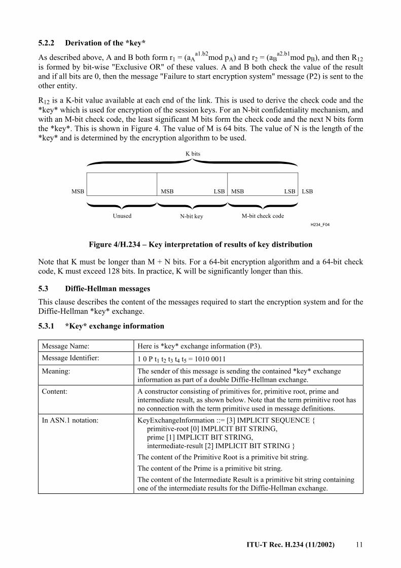
R12 is a K-bit value available at each end of the link. This is used to derive the check code and the *key* which is used for encryption of the session keys. For an N-bit confidentiality mechanism, and with an M-bit check code, the least significant M bits form the check code and the next N bits form the *key*. This is shown in Figure 4. The value of M is 64 bits. The value of N is the length of the *key* and is determined by the encryption algorithm to be used.
H234_F04
LSBMSB MSBLSB LSB
K bits
Unused N-bit key M-bit check code
MSB
Figure 4/H.234 – Key interpretation of results of key distribution
Note that K must be longer than M + N bits. For a 64-bit encryption algorithm and a 64-bit check code, K must exceed 128 bits. In practice, K will be significantly longer than this.
5.3 Diffie-Hellman messages This clause describes the content of the messages required to start the encryption system and for the Diffie-Hellman *key* exchange.
5.3.1 *Key* exchange information
Message Name: Here is *key* exchange information (P3). Message Identifier: 1 0 P t1 t2 t3 t4 t5 = 1010 0011 Meaning: The sender of this message is sending the contained *key* exchange
information as part of a double Diffie-Hellman exchange. Content: A constructor consisting of primitives for, primitive root, prime and
intermediate result, as shown below. Note that the term primitive root has no connection with the term primitive used in message definitions.
In ASN.1 notation: KeyExchangeInformation ::= [3] IMPLICIT SEQUENCE { primitive-root [0] IMPLICIT BIT STRING, prime [1] IMPLICIT BIT STRING, intermediate-result [2] IMPLICIT BIT STRING } The content of the Primitive Root is a primitive bit string. The content of the Prime is a primitive bit string. The content of the Intermediate Result is a primitive bit string containing one of the intermediate results for the Diffie-Hellman exchange.
12 ITU-T Rec. H.234 (11/2002)
5.3.2 Intermediate *key* exchange information
Message Name: Intermediate *key* exchange information (P4). Message Identifier: 1 0 P t1 t2 t3 t4 t5 = 1000 0100 Meaning: The sender of this message is sending the contained *key* exchange
information as part of a double Diffie-Hellman exchange. Content: A primitive bit string containing the intermediate result. In ASN.1 notation: IntermediateKeyExchangelnformation ::= [4] IMPLICIT BIT STRING The bit string for the intermediate result contains one of the intermediate
results for the Diffie-Hellman exchange. Messages P3 and P4 form a double D-H exchange that the final D-H
*key* is determined by both ends of a link.
5.3.3 Check code information from MCU
Message Name: Here is check code information from MCU (P5). Message Identifier: 1 0 P t1 t2 t3 t4 t5 = 1010 0101 Meaning: An MCU is sending the contained check code information resulting from
Diffie-Hellman exchanges. Content: A constructor for link identifier and check code. In ASN.1 notation: Link check code information :: = [5] IMPLICIT SEQUENCE {
link-identifier [0] IMPLICIT BIT STRING, check-code [1] IMPLICIT BIT STRING }
An MCU will send a (P5) message for each of the links that has completed Diffie-Hellman *key* exchange.
Note that the link identifier is used to identify which link from the MCU the check code relates to. A knowledge of the configuration of the MCU is required to interpret this identifier. (See also Note to 5.4 below.)
5.4 Extension for line checks In 5.2, an 64-bit check code was derived. This shall be presented by the terminal as all or part of a 16-digit hexadecimal number, the bit ordering being as shown in Figure 5 and using the terminology of Figure 4.
The value is presented to each user as shown; that is, the leftmost digit is derived from the MSB end of the check code. It is not necessary to present all the digits, the leftmost four probably being sufficient as there is then only a 1 in 216 chance of failing to detect a line problem. The value presented is conveyed by one user to the other verbally over the audiovisual channel; the other user must check that it corresponds to the value displayed on his terminal. NOTE – It is suggested that the verbal check can be made before the audio is actually encrypted; moreover, the timing of this process, and the alternative process for the multipoint situation described in 5.3.3, should be the same.

ITU-T Rec. H.234 (11/2002) 13
6 RSA based operation NOTE – Every reference in this clause to "key" is in the sense #key# mentioned in 3.3.2.
H234_F05
MSB LSB4 bits 4 bits 4 bits 4 bits 4 bits
MSB LSB
NOTE – Each 4-bit block of the check code forms a hexadecimal digit that will be displayed to the user.
16 digits
Hexadecimal digit Hexadecimal digit
Figure 5/H.234 – Bit ordering for line checks
6.1 Introduction
6.1.1 General This clause describes an RSA-based authentication framework for audiovisual services including both point-to-point and multipoint connections.
The authentication procedures and functions described are based on ITU-T Rec. X.509. In this Recommendation, authentication is established with the use of one or more levels of so-called Certification Authorities. A Certification Authority (CA) issues off-line certificates to entities or other CAs, which these entities or CAs can use to authenticate themselves to other entities and CAs. In the case of audiovisual services, the entities can be either user-terminals or trusted MCUs.
The specific authentication framework described here uses two levels of CAs. At the lowest level, each network domain, e.g. a country or a company, will have its own CA. In order to make authenticated interdomain audiovisual services possible, these CAs will have a common CA on a higher level to authenticate them. This common CA has to be a common point of trust for the users.
Where this is not possible, an alternative scheme exists, as briefly described in 6.5, though it is more complicated.
The CAs on the network domain level have to be trusted not to replicate identifying names in the certificates. It is assumed that the authentication itself has to be established in an untrusted environment. Furthermore, once an entity is authenticated it is trusted (until the call has ended).
6.1.2 Notation CA Certification Authority
CCA Country Certification Authority
GCA General Certification Authority
h[*] Result of function h applied to *
X<<Y>> The certificate of Y generated by X
Xp Public RSA key of entity X
Xs Secret RSA key of entity X
Xp[*] En/decryption of [*] with Xp. In the case of RSA this is performed by exponentiation
14 ITU-T Rec. H.234 (11/2002)
Xs[*] En/decryption of [*] with Xs. In the case of RSA this is performed by exponentiation
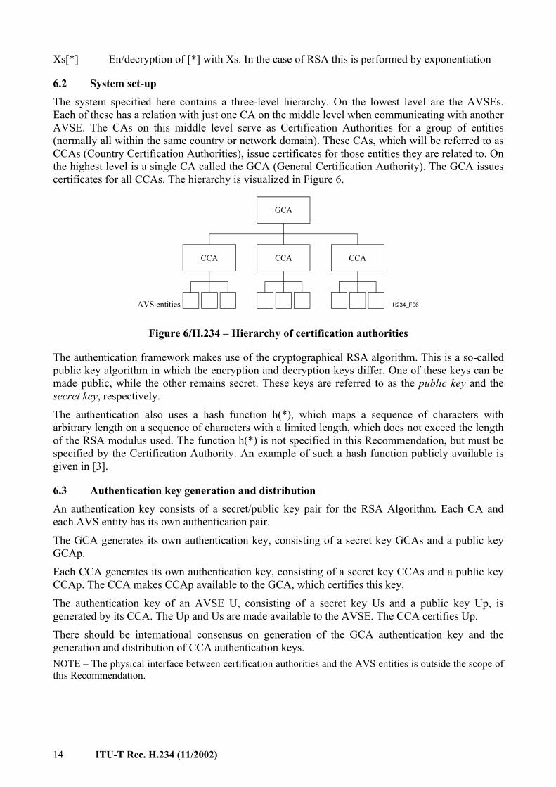
6.2 System set-up The system specified here contains a three-level hierarchy. On the lowest level are the AVSEs. Each of these has a relation with just one CA on the middle level when communicating with another AVSE. The CAs on this middle level serve as Certification Authorities for a group of entities (normally all within the same country or network domain). These CAs, which will be referred to as CCAs (Country Certification Authorities), issue certificates for those entities they are related to. On the highest level is a single CA called the GCA (General Certification Authority). The GCA issues certificates for all CCAs. The hierarchy is visualized in Figure 6.
H234_F06
GCA
CCA CCA CCA
AVS entities
Figure 6/H.234 – Hierarchy of certification authorities
The authentication framework makes use of the cryptographical RSA algorithm. This is a so-called public key algorithm in which the encryption and decryption keys differ. One of these keys can be made public, while the other remains secret. These keys are referred to as the public key and the secret key, respectively.
The authentication also uses a hash function h(*), which maps a sequence of characters with arbitrary length on a sequence of characters with a limited length, which does not exceed the length of the RSA modulus used. The function h(*) is not specified in this Recommendation, but must be specified by the Certification Authority. An example of such a hash function publicly available is given in [3].
6.3 Authentication key generation and distribution An authentication key consists of a secret/public key pair for the RSA Algorithm. Each CA and each AVS entity has its own authentication pair.
The GCA generates its own authentication key, consisting of a secret key GCAs and a public key GCAp.
Each CCA generates its own authentication key, consisting of a secret key CCAs and a public key CCAp. The CCA makes CCAp available to the GCA, which certifies this key.
The authentication key of an AVSE U, consisting of a secret key Us and a public key Up, is generated by its CCA. The Up and Us are made available to the AVSE. The CCA certifies Up.
There should be international consensus on generation of the GCA authentication key and the generation and distribution of CCA authentication keys. NOTE – The physical interface between certification authorities and the AVS entities is outside the scope of this Recommendation.
ITU-T Rec. H.234 (11/2002) 15
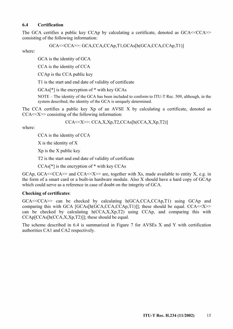
6.4 Certification The GCA certifies a public key CCAp by calculating a certificate, denoted as GCA<<CCA>> consisting of the following information:
GCA<<CCA>>: GCA,CCA,CCAp,T1,GCAs[h(GCA,CCA,CCAp,T1)] where:
GCA is the identity of GCA
CCA is the identity of CCA
CCAp is the CCA public key
T1 is the start and end date of validity of certificate
GCAs[*] is the encryption of * with key GCAs NOTE – The identity of the GCA has been included to conform to ITU-T Rec. 509, although, in the system described, the identity of the GCA is uniquely determined.
The CCA certifies a public key Xp of an AVSE X by calculating a certificate, denoted as CCA<<X>> consisting of the following information:
CCA<<X>>: CCA,X,Xp,T2,CCAs[h(CCA,X,Xp,T2)] where:
CCA is the identity of CCA
X is the identity of X
Xp is the X public key
T2 is the start and end date of validity of certificate
CCAs[*] is the encryption of * with key CCAs
GCAp, GCA<<CCA>> and CCA<<X>> are, together with Xs, made available to entity X, e.g. in the form of a smart card or a built-in hardware module. Also X should have a hard copy of GCAp which could serve as a reference in case of doubt on the integrity of GCA.
Checking of certificates: GCA<<CCA>> can be checked by calculating h(GCA,CCA,CCAp,T1) using GCAp and comparing this with GCA [GCAs[h(GCA,CCA,CCAp,T1)]]; these should be equal. CCA<<X>> can be checked by calculating h(CCA,X,Xp,T2) using CCAp, and comparing this with CCAp[CCAs[h(CCA,X,Xp,T2)]]; these should be equal.
The scheme described in 6.4 is summarized in Figure 7 for AVSEs X and Y with certification authorities CA1 and CA2 respectively.

16 ITU-T Rec. H.234 (11/2002)
H234_F07
AVSEX
AVSEY
Certification
Authentication
GCA
CA1 CA2
GCA<<CA1>> GCA<<CA2>>
GCA<<CA1>>CA1<<X>>
GCA<<CA2>>CA2<<Y>>
GCA<<CA1>>, CA1<<X>>
GCA<<CA2>>, CA2<<Y>>
Figure 7/H.234 – Summary of certification procedure
6.5 Alternative solution for certification without a GCA If two network operators/companies want their AVSEs to authenticate each other, their certification authorities CA1 and CA2 must certify each other by exchanging certificates CA1<<CA2>> and CA2<<CA1>>. This system will be complex in operation, since AVSEs X and Y might have to enter an external directory to obtain either CA1<<CA2>> or CA2<<CA1>> and also have to exchange the identities of their certification authorities beforehand. This is detailed in Figure 8.
H234_F08
Directory Directory
Entity X Entity Y
Certification
Authentication
CA1 CA2
CA2, CA1<<CA2>>, CA2<<Y>>
CA1, CA2<<CA1>>, CA1<<X>>
CA2<<CA1>> CA1<<CA2>>CA1<<X>> CA2<<Y>>
CA1<<CA2>>
CA2<<CA1>>
Figure 8/H.234 – Certification without a higher certification authority
6.6 Authentication of entities The authentication procedure is detailed below; it applies on all possible connections, i.e. MCU-MCU, Terminal MCU, MCU-Terminal and Terminal-Terminal.
The authentication procedure between two entities at call set-up involves four messages: – RSA.P1 – Authentication initiation; – RSA.P2 – Authentication response; – RSA.P3 – Authentication complete; – RSA.P4 – Authentication failed.
RSA.P1 and RSA.P3 are sent by the initiating entity denoted by X, RSA.P2 by the called entity denoted by Y. The CCAs of X and Y are denoted by CX and CY, respectively.

ITU-T Rec. H.234 (11/2002) 17
The content of RSA.P1 is: GCA<<CX>>,CX<<X>>,RX,Y,Xs[h(RX,Y)]
where RX is a random number generated by X.
Y now: 1) obtains Xp from RSA.P1 and checks Xp using the certificates with GCAp as a point of
trust; 2) checks the integrity of the message by calculating h(RX,Y) and comparing this with
Xp[Xs[h(RX,Y)]]; these should be equal; 3) checks the expiry dates of the certificates; 4) checks the integrity of X.
The content of RSA.P2 is: GCA<<CY>>,CY<<Y>>,RY,X,RX,Xp[KY],Ys[h(RY,X,RX,KY)]
where RY is a random number and KY is key data (see 3.3.2), both generated by Y.
X now: 1) obtains Yp from RSA.P2 and checks Yp using the certificates with GCAp as a point of
trust; 2) decrypts Xp[KY], obtaining KY; 3) checks the integrity of the message by calculating h(RY,X,RX,KY) and comparing this
with Yp[Ys[h(RY,X,RX,KY]]; these should be equal; 4) checks the expiry dates of the certificates; 5) checks that RX is the same as sent in RSA.P1; 6) checks the integrity of Y.
The content of RSA.P3 is: RY,Y,Yp[KX],Xs[h(RY,Y,KX)]
where KX is key data generated by X.
Y now: 1) decrypts Yp[KX], obtaining KX; 2) checks the integrity of the message by calculating h(RY,Y,KX) and comparing this with
Xp[Xs[h(RY,Y,KX)]] ; these should be equal; 3) checks that RY is the same as sent in RSA.P2; 4) checks the integrity of X.
If any of the checks on RSA.P1, RSA.P2 or RSA.P3 fail, the call set-up should be broken by sending a message RSA.P4 – Authentication failed. RSA.P4 can be sent by both X and Y and after either RSA.P1, RSA.P2 or RSA.P3. Sending RSA.P4 should invoke termination of the call set-up procedure. NOTE 1 − It is possible to speed up RSA calculations by choosing specific public parameters. NOTE 2 − This scheme differs from the original X.509 specification in that KX is sent in RSA.P3 and not in RSA.P1. This has the advantage that X does not have to obtain Yp from a directory. For both X and Y, GCAp is the only point of trust: as long as this key is trusted and the secret information of an entity is trusted not to be stolen, X and Y do not need to access directories. Also in RSA.P3, the identity of Y is added for security reasons and in RSA.P2 and RSA.P3 the signature is over the unencrypted key data KY and KX, respectively.
18 ITU-T Rec. H.234 (11/2002)
6.6.1 Simultaneous transmission of RSA.P1 messages If entity X sends to an entity Y an initiating message:
RSA.P1(X–>Y): GCA<<CX>>,CX<<X>>,RX,Y,Xs[h(RX,Y)]
and, before receiving RSA.P2(Y–>X), Y sends to X an initiating message:
RSA.P1(Y–>X): GCA<<CY>>,CY<<Y>>,RY,X,Ys[h(RY,X)]
then X and Y will resolve this situation by comparing RX and RY.
If RX>RY the message RSA.P1(Y–>X) should be neglected and Y should respond with a message RSA.P2.
If RY>RX the message RSA.P1(X–>Y) should be neglected and X should respond with a message RSA.P2.
If coincidentally RX = RY, both messages RSA.P1 should be neglected and the authentication procedure should be terminated with the sending of a message: RSA.P4 (authentication failed).
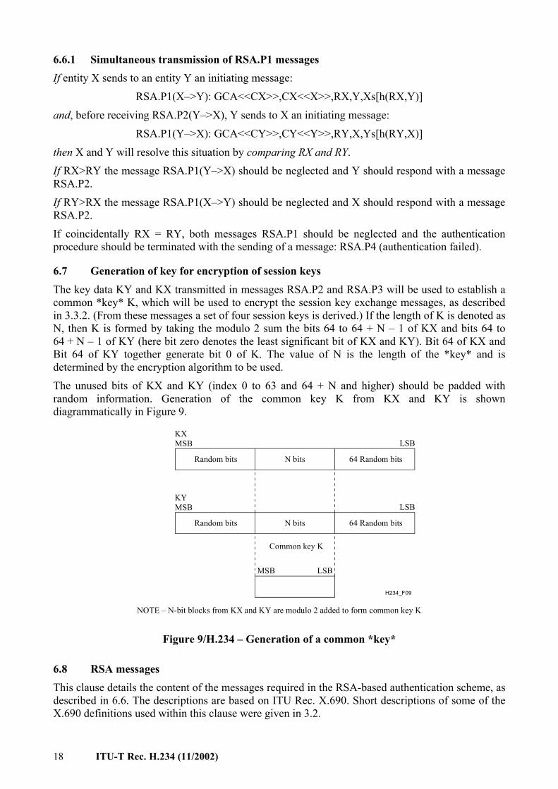
6.7 Generation of key for encryption of session keys The key data KY and KX transmitted in messages RSA.P2 and RSA.P3 will be used to establish a common *key* K, which will be used to encrypt the session key exchange messages, as described in 3.3.2. (From these messages a set of four session keys is derived.) If the length of K is denoted as N, then K is formed by taking the modulo 2 sum the bits 64 to 64 + N – 1 of KX and bits 64 to 64 + N – 1 of KY (here bit zero denotes the least significant bit of KX and KY). Bit 64 of KX and Bit 64 of KY together generate bit 0 of K. The value of N is the length of the *key* and is determined by the encryption algorithm to be used.
The unused bits of KX and KY (index 0 to 63 and 64 + N and higher) should be padded with random information. Generation of the common key K from KX and KY is shown diagrammatically in Figure 9.
H234_F09
Random bits 64 Random bitsN bits
N bitsRandom bits 64 Random bits
Common key K
NOTE – N-bit blocks from KX and KY are modulo 2 added to form common key K
KXMSB
KYMSB
LSB
LSB
LSBMSB
Figure 9/H.234 – Generation of a common *key*
6.8 RSA messages This clause details the content of the messages required in the RSA-based authentication scheme, as described in 6.6. The descriptions are based on ITU Rec. X.690. Short descriptions of some of the X.690 definitions used within this clause were given in 3.2.

ITU-T Rec. H.234 (11/2002) 19
6.8.1 Authentication initiation
Message Name: Authentication Initiation (RSA.P1). Message Identifier: 1 0 P t1 t2 t3 t4 t5 = 1010 0111 Meaning: The sender of this message wants to start an authentication procedure with
the intended receiver and sends information needed to start the procedure. Content: A constructor, consisting of two constructors for the certificates
GCA<<CX>> and CX<<X>> and three primitives for a random number RX, an identity Y and encrypted hashed information Xs[h(RX,Y)].
In ASN.1 notation: RSA-P1 ::= [7] IMPLICIT SEQUENCE { GCA-certificate-for-CCA [0] IMPLICIT GCA-Certificate, CCA-certificate-for-entity [1] IMPLICIT CCA-Certificate, calling-entity-random-number [2] IMPLICIT BIT STRING, called-entity-identity [3] IMPLICIT BIT STRING, hashed-information-in-calling-secret-key [4] IMPLICIT BIT STRING }
The content of Calling-Entity-Random-Number is a primitive bit string.
The content of Called-Entity-Identity is a primitive bit string.
The content of Hashed-Information-In-Calling-Secret-Key is a primitive bit string.
Content of GCA-Certificate-For-CCA: A constructor consisting of five primitives for an identity GCA, an identity CCA, a public key CCAp, a validity date range T1 and encrypted hashed information GCAs[h(GCA,CCA,CCAp,T1)].
In ASN.1 notation:
GCA-Certificate::= SEQUENCE{GCA-identity [0] IMPLICIT BIT STRING,
CCA-identity [1] IMPLICIT BIT STRING,
CCA-public-key [2] IMPLICIT BIT STRING,
certificate-valid-date-range [3] IMPLICIT BIT STRING,
hashed-information-in-GCA-secret-key [4] IMPLICIT BIT STRING}
The content of GCA-Identity is a primitive bit string.
The content of CCA-Identity is a primitive bit string.
The content of CCA-Public-Key is a primitive bit string.
The content of Certificate-Valid-Date-Range is a primitive bit string.
The content of Hashed-Information-In-GCA-Secret-Key is a primitive bit string.
Content of CCA-Certificate-For-Entity: A constructor consisting of five primitives for an identity CCA, an identity of entity X, a public key Xp, a validity date range T2 and encrypted hashed information CCAs[h(CCA,X,Xp,T2)].
In ASN.1 notation:
CCA-Certificate:: =SEQUENCE{CCA-identity [0] IMPLICIT BIT STRING,
entity-identity [1] IMPLICIT BIT STRING,
entity-public-key [2] IMPLICIT BIT STRING,
certificate-valid-date-range [3] IMPLICIT BIT STRING,
hashed-information-in-CCA-secret-key [4] IMPLICIT BIT STRING}

20 ITU-T Rec. H.234 (11/2002)
The content of CCA-Identity is a primitive bit string.
The content of Entity-Identity is a primitive bit string.
The content of Entity-Public-Key is a primitive bit string.
The content of Certificate-Valid-Date-Range is a primitive bit string.
The content of Hashed-Information-In-CCA-Secret-Key is a primitive bit string.
6.8.2 Authentication response
Message Name: Authentication Response (RSA.P2). Message Identifier: 1 0 P t1 t2 t3 t4 t5 = 1010 1000 Meaning: The sender of this message responds to an authentication initiation and
sends information needed for the authentication procedure. Content: A constructor, consisting of two constructors for the certificates
GCA<<CY>>and CY<<Y>> and five primitives for a random number RY, an identity X, a random number RX, encrypted key information Xp[KY] and encrypted hashed information Ys[h(RY,X,RX,KY)].
In ASN.1 notation: RSA.P2 ::= [8] IMPLICIT SEQUENCE { GCA-certificate-for-CCA [0] IMPLICIT GCA-Certificate, CCA-certificate-for-entity [1] IMPLICIT CCA-Certificate, called-entity-random-number [2] IMPLICIT BIT STRING, calling-entity-identity [3] IMPLICIT BIT STRING, calling-entity-random-number [4] IMPLICIT BIT STRING, key-information-in-calling-public-key [5] IMPLICIT BIT STRING, hashed-information-in-called-secret-key [6] IMPLICIT BIT STRING }
The content of Called-Entity-Random-Number is a primitive bit string.
The content of Calling-Entity-Identity is a primitive bit string.
The content of Calling-Entity-Random-Number is a primitive bit string.
The content of Key-Information-In-Calling-Public-Key is a primitive bit string.
The content of Hashed-Information-In-Called-Secret-Key is a primitive bit string.
The contents of GCA-Certificate-For-CCA and CCA-Certificate-For-Entity are similar to the descriptions given in 6.8.1.
6.8.3 Authentication complete
Message Name: Authentication Complete (RSA.P3). Message Identifier: 1 0 P t1 t2 t3 t4 t5 = 1010 1001 Meaning: The sender of this message, being the initiator of the authentication
procedure, sends the information needed to complete the authentication procedure.
Content: A constructor, consisting of four primitives for a random number RY, an identity Y, encrypted key information Yp[KX] and encrypted hashed information Xs[h(RY,Y,KX)], as detailed in the figure below.
In ASN.1 notation: RSA.P3 ::= [9] IMPLICIT SEQUENCE { called-entity-random-number [0] IMPLICIT BIT STRING, called-entity-identity [1] IMPLICIT BIT STRING, key-information-in-called-public-key [2] IMPLICIT BIT STRING, hashed-information-in-calling-secret-key [3] IMPLICIT BIT STRING }
ITU-T Rec. H.234 (11/2002) 21
The content of Called-Entity-Random-Number is a primitive bit string.
The content of Called-Entity-Identity is a primitive bit string.
The content of Key-Information-In-Called-Public-Key is a primitive bit string.
The content of Hashed-Information-In-Calling-Secret-Key is a primitive bit string.
6.8.4 Authentication failed
Message Name: Authentication Failed (RSA.P4). Message Identifier: 1 0 P t1 t2 t3 t4 t5 = 1000 1010 Meaning: The sender of this message indicates that something has gone wrong
during the authentication procedure and that the authentication procedure will be terminated. Sending or receiving this message should invoke termination of the call set-up procedure.
Content: This message has no content.
7 MCU operation In the case of a "trusted MCU" (in which the signals are all decrypted at the inputs to the MCU, and therefore the MCU must be in a secure location), the communications between each audiovisual terminal and the MCU may be encrypted as described in this Recommendation for a point-to-point link. Clearly this method is not applicable to the connection of telephone terminals to the conference via the analogue telephone network.
There is no provision in this Recommendation for operation of an MCU without such decryption.
Bibliography [1] DIFFIE (W.), HELLMAN (M.): New directions in cryptography, IEEE Transactions IT-22, 6,
pp. 644-654, (Nov. 1976).
[2] RIVEST (R. L.), SHAMIR (A.), ADLEMAN (L.): A Method for Obtaining Digital Signatures and Public-Key Cryptosystems, Communications of the ACM, 21, 2, pp. 120-126, (February, 1978).
[3] The MD4 Message Digest Algorithm, RSA Data Security Inc., Redwood City, California 94065.


Printed in Switzerland Geneva, 2003
SERIES OF ITU-T RECOMMENDATIONS
Series A Organization of the work of ITU-T
Series B Means of expression: definitions, symbols, classification
Series C General telecommunication statistics
Series D General tariff principles
Series E Overall network operation, telephone service, service operation and human factors
Series F Non-telephone telecommunication services
Series G Transmission systems and media, digital systems and networks
Series H Audiovisual and multimedia systems
Series I Integrated services digital network
Series J Cable networks and transmission of television, sound programme and other multimedia signals
Series K Protection against interference
Series L Construction, installation and protection of cables and other elements of outside plant
Series M TMN and network maintenance: international transmission systems, telephone circuits, telegraphy, facsimile and leased circuits
Series N Maintenance: international sound programme and television transmission circuits
Series O Specifications of measuring equipment
Series P Telephone transmission quality, telephone installations, local line networks
Series Q Switching and signalling
Series R Telegraph transmission
Series S Telegraph services terminal equipment
Series T Terminals for telematic services
Series U Telegraph switching
Series V Data communication over the telephone network
Series X Data networks and open system communications
Series Y Global information infrastructure and Internet protocol aspects
Series Z Languages and general software aspects for telecommunication systems