Embed Size (px)
Citation preview

I n t e r n a t i o n a l T e l e c o m m u n i c a t i o n U n i o n
ITU-T G.984.3TELECOMMUNICATION STANDARDIZATION SECTOR OF ITU
(03/2008)
SERIES G: TRANSMISSION SYSTEMS AND MEDIA, DIGITAL SYSTEMS AND NETWORKS Digital sections and digital line system – Optical line systems for local and access networks
Gigabit-capable Passive Optical Networks (G-PON): Transmission convergence layer specification
Recommendation ITU-T G.984.3

ITU-T G-SERIES RECOMMENDATIONS TRANSMISSION SYSTEMS AND MEDIA, DIGITAL SYSTEMS AND NETWORKS
INTERNATIONAL TELEPHONE CONNECTIONS AND CIRCUITS G.100–G.199 GENERAL CHARACTERISTICS COMMON TO ALL ANALOGUE CARRIER-TRANSMISSION SYSTEMS
G.200–G.299
INDIVIDUAL CHARACTERISTICS OF INTERNATIONAL CARRIER TELEPHONE SYSTEMS ON METALLIC LINES
G.300–G.399
GENERAL CHARACTERISTICS OF INTERNATIONAL CARRIER TELEPHONE SYSTEMS ON RADIO-RELAY OR SATELLITE LINKS AND INTERCONNECTION WITH METALLIC LINES
G.400–G.449
COORDINATION OF RADIOTELEPHONY AND LINE TELEPHONY G.450–G.499 TRANSMISSION MEDIA AND OPTICAL SYSTEMS CHARACTERISTICS G.600–G.699 DIGITAL TERMINAL EQUIPMENTS G.700–G.799 DIGITAL NETWORKS G.800–G.899 DIGITAL SECTIONS AND DIGITAL LINE SYSTEM G.900–G.999
General G.900–G.909 Parameters for optical fibre cable systems G.910–G.919 Digital sections at hierarchical bit rates based on a bit rate of 2048 kbit/s G.920–G.929 Digital line transmission systems on cable at non-hierarchical bit rates G.930–G.939 Digital line systems provided by FDM transmission bearers G.940–G.949 Digital line systems G.950–G.959 Digital section and digital transmission systems for customer access to ISDN G.960–G.969 Optical fibre submarine cable systems G.970–G.979 Optical line systems for local and access networks G.980–G.989 Access networks G.990–G.999
QUALITY OF SERVICE AND PERFORMANCE – GENERIC AND USER-RELATED ASPECTS
G.1000–G.1999
TRANSMISSION MEDIA CHARACTERISTICS G.6000–G.6999 DATA OVER TRANSPORT – GENERIC ASPECTS G.7000–G.7999 PACKET OVER TRANSPORT ASPECTS G.8000–G.8999 ACCESS NETWORKS G.9000–G.9999
For further details, please refer to the list of ITU-T Recommendations.

Rec. ITU-T G.984.3 (03/2008) i
Recommendation ITU-T G.984.3
Gigabit-capable Passive Optical Networks (G-PON): Transmission convergence layer specification
Summary Recommendation ITU-T G.984.3 describes the transmission convergence layer for gigabit-capable passive optical networks – a family of flexible access networks capable of providing a range of broadband and narrow-band services, operating at the rates of 2.48832 Gbit/s downstream, and 1.24416 or 2.48832 Gbit/s upstream. This Recommendation includes the specifications of the following: • gigabit PON transmission convergence (GTC) layer framing; • upstream time division multiple access mechanism; • physical layer OAM messaging channel; • principles and signalling mechanism of the upstream dynamic bandwidth assignment; • ONU activation method; • forward error correction; • security.
This Recommendation forms an integral part of the G.984-series of ITU-T Recommendations that, together, specify a single coherent set of access transmission systems.
The original version of Recommendation ITU-T G.984.3 was approved on 22 February 2004. It was subsequently expanded and complemented by Amendment 1 (07/2005), Amendment 2 (03/2006), Amendment 3 (12/2006) as well as the Implementers' Guide (06/2006).
This version of Recommendation ITU-T G.984.3 integrates all the earlier documents listed in the previous paragraph, providing necessary corrections and clarifications, and contains the new results of the standardization work performed by ITU-T Study Group 15 during the 2005-2008 study period.
Source Recommendation ITU-T G.984.3 was approved on 29 March 2008 by ITU-T Study Group 15 (2005-2008) under Recommendation ITU-T A.8 procedure.

ii Rec. ITU-T G.984.3 (03/2008)
FOREWORD
The International Telecommunication Union (ITU) is the United Nations specialized agency in the field of telecommunications, information and communication technologies (ICTs). The ITU Telecommunication Standardization Sector (ITU-T) is a permanent organ of ITU. ITU-T is responsible for studying technical, operating and tariff questions and issuing Recommendations on them with a view to standardizing telecommunications on a worldwide basis.
The World Telecommunication Standardization Assembly (WTSA), which meets every four years, establishes the topics for study by the ITU-T study groups which, in turn, produce Recommendations on these topics.
The approval of ITU-T Recommendations is covered by the procedure laid down in WTSA Resolution 1.
In some areas of information technology which fall within ITU-T's purview, the necessary standards are prepared on a collaborative basis with ISO and IEC.
NOTE
In this Recommendation, the expression "Administration" is used for conciseness to indicate both a telecommunication administration and a recognized operating agency.
Compliance with this Recommendation is voluntary. However, the Recommendation may contain certain mandatory provisions (to ensure e.g. interoperability or applicability) and compliance with the Recommendation is achieved when all of these mandatory provisions are met. The words "shall" or some other obligatory language such as "must" and the negative equivalents are used to express requirements. The use of such words does not suggest that compliance with the Recommendation is required of any party.
INTELLECTUAL PROPERTY RIGHTS
ITU draws attention to the possibility that the practice or implementation of this Recommendation may involve the use of a claimed Intellectual Property Right. ITU takes no position concerning the evidence, validity or applicability of claimed Intellectual Property Rights, whether asserted by ITU members or others outside of the Recommendation development process.
As of the date of approval of this Recommendation, ITU had received notice of intellectual property, protected by patents, which may be required to implement this Recommendation. However, implementers are cautioned that this may not represent the latest information and are therefore strongly urged to consult the TSB patent database at http://www.itu.int/ITU-T/ipr/.
© ITU 2009
All rights reserved. No part of this publication may be reproduced, by any means whatsoever, without the prior written permission of ITU.

Rec. ITU-T G.984.3 (03/2008) iii
CONTENTS
Page 1 Scope ............................................................................................................................ 1
2 References..................................................................................................................... 1
3 Definitions .................................................................................................................... 2
4 Abbreviations and acronyms ........................................................................................ 4
5 Conventions and terminology....................................................................................... 7 5.1 ONT and ONU ............................................................................................... 7 5.2 Data encapsulation method and deprecation of ATM transport..................... 7 5.3 Traffic monitoring versus non-status-reporting.............................................. 8 5.4 Bandwidth assignment versus bandwidth allocation...................................... 8 5.5 G-PON time division multiplexing architecture............................................. 9 5.6 Disambiguation of the concept of frame ........................................................ 11 5.7 Concepts associated with upstream physical layer overhead ......................... 12
6 G-PON system architecture .......................................................................................... 12 6.1 Network architecture and reference configuration ......................................... 12 6.2 Parameters of the GTC layer .......................................................................... 12 6.3 Functional blocks............................................................................................ 13 6.4 Interoperability between G-PON and B-PON................................................ 14
7 G-PON transmission convergence layer overview....................................................... 15 7.1 GTC protocol stack......................................................................................... 15 7.2 GTC key functions ......................................................................................... 19 7.3 Functions of Sublayers in GTC ...................................................................... 20 7.4 Dynamic bandwidth assignment..................................................................... 20 7.5 Resource allocation and quality of service (QoS) .......................................... 29
8 GTC layer framing........................................................................................................ 30 8.1 Downstream GTC frame structure ................................................................. 30 8.2 Upstream burst structure................................................................................. 36 8.3 Mapping of GEM frames into GTC payload.................................................. 40 8.4 Status reporting DBA signalling and configuration ....................................... 44
9 GTC messages .............................................................................................................. 48 9.1 PLOAM message format ................................................................................ 48 9.2 Control messages............................................................................................ 49
10 Activation method ........................................................................................................ 64 10.1 Overview ........................................................................................................ 64 10.2 Activation mechanism at the ONU................................................................. 65 10.3 OLT support of the activation process ........................................................... 73 10.4 OLT and ONU timing relationships ............................................................... 75 10.5 Power levelling............................................................................................... 83

iv Rec. ITU-T G.984.3 (03/2008)
Page 11 Alarms and performance monitoring............................................................................ 83
11.1 Alarms ............................................................................................................ 83 11.2 Performance monitoring................................................................................. 89
12 Security ......................................................................................................................... 89 12.1 Basic threat model .......................................................................................... 89 12.2 Encryption system .......................................................................................... 90 12.3 Key exchange and switch-over....................................................................... 91
13 Forward error correction............................................................................................... 92 13.1 Introduction .................................................................................................... 92 13.2 Downstream FEC ........................................................................................... 94 13.3 Upstream FEC ................................................................................................ 96 13.4 ONU activation transmissions........................................................................ 99
14 OMCI transport mechanism ......................................................................................... 100 14.1 OMCI transport schema ................................................................................. 100 14.2 OMCI adapters ............................................................................................... 100
Annex A – Implementers' guide for Recommendation UIT-T G.984.3 .................................. 101 A.1 Introduction .................................................................................................... 101 A.2 AES mechanism and golden vectors .............................................................. 101 A.3 FEC encoding golden vector .......................................................................... 104 A.4 Scrambler diagram.......................................................................................... 106 A.5 A downstream frame example........................................................................ 106 A.6 ONU activation process.................................................................................. 107 A.7 PLOAM messages .......................................................................................... 114 A.8 Transmitter block diagram ............................................................................. 115
Appendix I – Transport of user traffic over GEM channels .................................................... 116 I.1 Mapping of GEM frames into the GTC payload............................................ 116 I.2 TDM over GEM ............................................................................................. 116 I.3 Ethernet over GEM......................................................................................... 117 I.4 SDH over GEM .............................................................................................. 118 I.5 IP over GEM................................................................................................... 120
Appendix II – Survivability in GTC-based systems ................................................................ 121
Appendix III – GEM header error control decoding................................................................ 122
Appendix IV – OLT activation procedures overview.............................................................. 124 IV.1 Common part .................................................................................................. 124 IV.2 ONU-specific part .......................................................................................... 127 IV.3 Automatic ONU Discovery Method............................................................... 129 IV.4 POPUP process............................................................................................... 130

Rec. ITU-T G.984.3 (03/2008) v
Page Appendix V – Downstream line data pattern conditioning...................................................... 132
V.1 Idle pattern control ......................................................................................... 132 V.2 Intentional PON disruption............................................................................. 134
Bibliography ............................................................................................................................ 135


Rec. ITU-T G.984.3 (03/2008) 1
Recommendation ITU-T G.984.3
Gigabit-capable Passive Optical Networks (G-PON): Transmission convergence layer specification
1 Scope This Recommendation is intended to: • Describe flexible access networks using optical fibre technology. The focus is primarily on
a network to support services including POTS, data, video, leased line and distributive services.
• Describe characteristics of a passive optical network (PON) with the capability of transporting various services between the user-network interface and the service node interface.
• Concentrate on the fibre issues. The copper issues of hybrid systems are described elsewhere, e.g., xDSL standardization.
• Cover transmission convergence (TC) issues between the service node interface and the user-network interface.
• Deal with specifications for frame format, media access control method, ranging method, OAM functionality and security in G-PON networks.
2 References The following ITU-T Recommendations and other references contain provisions which, through reference in this text, constitute provisions of this Recommendation. At the time of publication, the editions indicated were valid. All Recommendations and other references are subject to revision; users of this Recommendation are therefore encouraged to investigate the possibility of applying the most recent edition of the Recommendations and other references listed below. A list of the currently valid ITU-T Recommendations is regularly published. The reference to a document within this Recommendation does not give it, as a stand-alone document, the status of a Recommendation.
[ITU-T G.704] Recommendation ITU-T G.704 (1998), Synchronous frame structures used at 1544, 6312, 2048, 8448 and 44 736 kbit/s hierarchical levels.
[ITU-T G.707] Recommendation ITU-T G.707/Y.1322 (2007), Network node interface for the synchronous digital hierarchy (SDH).
[ITU-T G.803] Recommendation ITU-T G.803 (2000), Architecture of transport networks based on the synchronous digital hierarchy (SDH).
[ITU-T G.983.1] Recommendation ITU-T G.983.1 (2005), Broadband optical access systems based on Passive Optical Networks (PON).
[ITU-T G.983.4] Recommendation ITU-T G.983.4 (2001), A broadband optical access system with increased service capability using dynamic bandwidth assignment.
[ITU-T G.983.5] Recommendation ITU-T G.983.5 (2002), A broadband optical access system with enhanced survivability.
[ITU-T G.984.1] Recommendation ITU-T G.984.1 (2008), Gigabit-capable passive optical networks (G-PON): General characteristics.

2 Rec. ITU-T G.984.3 (03/2008)
[ITU-T G.984.2] Recommendation ITU-T G.984.2 (2003), Gigabit-capable passive optical networks (G-PON): Physical Media Dependent (PMD) layer specification.
[ITU-T I.432.1] Recommendation ITU-T I.432.1 (1999), B-ISDN user-network interface – Physical layer specification: General characteristics.
[IEEE 802.3] IEEE 802.3 (2005), Part 3: Carrier sense multiple access with collision detection (CSMA/CD) access method and physical layer specifications. <http://ieeexplore.ieee.org/servlet/opac?punumber=10531>
[FIPS 197] Federal Information Processing Standard 197 (2001), Advanced Encryption Standard. <http://csrc.nist.gov/publications/fips/fips197/fips-197.pdf>
[FIPS 81] Federal Information Processing Standard 81 (1980), DES Modes of Operation. <http://csrc.nist.gov/publications/fips/fips81/fips81.htm>
[FIPS 140-2] Federal Information Processing Standard 140-2 (2001), Security Requirements for cryptographic modules. <http://csrc.nist.gov/publications/fips/fips140-2/fips1402.pdf>
3 Definitions This Recommendation defines the following terms:
3.1 activation: A set of distributed procedures executed by the OLT and the ONUs that allows an inactive ONU to join or resume operations on the PON. The activation process includes three phases: parameter learning, serial number acquisition, and ranging.
3.2 bandwidth allocation: An upstream transmission opportunity granted by the OLT for the duration of the specified time interval to the specified traffic-bearing entity within an ONU.
3.3 C/M-plane: A plane of the G-PON protocol suite that handles control and management information in a G-PON system. Data on OMCI is transferred through this plane.
3.4 dynamic bandwidth assignment (DBA): A process by which the optical line terminal (OLT) distributes the upstream PON capacity between the traffic-bearing entities within optical network units (ONUs), based on the dynamic indication of their activity status and their configured traffic contracts.
3.5 embedded OAM: An operation and management channel between the OLT and the ONUs that utilizes the structured overhead fields of the downstream GTC frame and upstream GTC burst, and supports the time sensitive functions, including bandwidth allocation, key synchronization and DBA reporting.
3.6 equalization delay (EqD): The requisite delay assigned by the OLT to an individual ONU as a result of ranging.
3.7 G-PON encapsulation method (GEM): A data frame transport scheme used in G-PON systems that is connection-oriented and that supports fragmentation of the user data frames into variable-sized transmission fragments.
3.8 G-PON transmission convergence (GTC) layer: A protocol layer of the G-PON protocol suite that is positioned between the physical media dependent (PMD) layer and the G-PON clients. The GTC layer is composed of GTC framing sublayer and GTC adaptation sublayer.
3.9 GEM port: An abstraction on the GTC adaptation sublayer representing a logical connection associated with a specific client packet flow.

Rec. ITU-T G.984.3 (03/2008) 3
3.10 gigabit-capable passive optical network (G-PON): A variant of the passive optical network (PON) access technology supporting transmission rates in excess of 1 Gbit/s and based on the G.984-series of ITU-T Recommendations.
3.11 GTC adaptation sublayer: A sublayer of the G-PON transmission convergence layer that supports the functions of user data fragmentation and de-fragmentation, GEM encapsulation, GEM frame delineation and GEM Port-ID filtering.
3.12 GTC framing sublayer: A sublayer of the G-PON transmission convergence layer that supports the functions of GTC frame/burst encapsulation and delineation, embedded OAM processing and Alloc-ID filtering.
3.13 optical access network (OAN): A set of access links sharing the same network-side interfaces and supported by optical access transmission systems. The OAN may include a number of ODNs connected to the same OLT.
3.14 optical distribution network (ODN): In the PON context, a tree of optical fibres in the access network, supplemented with power or wavelength splitters, filters or other passive optical devices.
3.15 optical line termination (OLT): A device that terminates the common (root) endpoint of an ODN, implements a PON protocol, such as that defined by [ITU-T G.984.1] and adapts PON PDUs for uplink communications over the provider service interface. The OLT provides management and maintenance functions for the subtended ODN and ONUs.
3.16 optical network termination (ONT): A single-subscriber device that terminates any one of the distributed (leaf) endpoints of an ODN, implements a PON protocol and adapts PON PDUs to subscriber service interfaces. An ONT is a special case of an ONU.
3.17 optical network unit (ONU): A generic term denoting a device that terminates any one of the distributed (leaf) endpoints of an ODN, implements a PON protocol and adapts PON PDUs to subscriber service interfaces. In some contexts, an ONU implies a multiple subscriber device.
3.18 physical layer OAM (PLOAM): A message-based operation and management channel between the OLT and the ONUs that supports the PON TC-layer management functions, including ONU activation, OMCC establishment, encryption configuration, key management and alarm signalling.
3.19 pre-assigned delay (PrD): The requisite delay that all the ONUs on the PON are required to use prior to completion of the ranging phase of the activation process.
3.20 quiet window: A time interval during which the OLT suppresses all the bandwidth allocations to the in-service ONUs in order to avoid collisions between their upstream transmissions and the transmission bursts from the ONUs that have just joined the PON and are undergoing the activation process.
3.21 ranging: A procedure of measuring the logical distance between the OLT and each of its subtending ONUs with the objective to accurately time the individual ONU upstream transmission bursts so that these bursts arrive at the OLT in a collision-free sequential fashion and the upstream overhead, which is required to ensure burst detection and delineation, is minimal. Ranging is performed during the ONU activation and may be performed while the ONU is in service.
3.22 requisite delay: A general term denoting the total extra delay the OLT may require an ONU to apply to the upstream transmission beyond the ONU's regular response time. The purpose of the requisite delay is to compensate for variation of propagation and processing delays of individual ONUs, and to avoid or reduce the probability of collisions between upstream transmissions.

4 Rec. ITU-T G.984.3 (03/2008)
3.23 status reporting DBA (SR-DBA): A method of dynamic bandwidth assignment that infers the dynamic activity status of the traffic-bearing entities within optical network units (ONUs) based on the explicit buffer occupancy reports communicated over the embedded OAM channel.
3.24 traffic-monitoring DBA (TM-DBA): A method of dynamic bandwidth assignment that infers the dynamic activity status of the traffic-bearing entities within optical network units (ONUs) based on the observation of the idle GEM frame transmissions in place of granted upstream bandwidth allocations.
3.25 transmission container (T-CONT): A traffic-bearing object within an ONU that represents a group of logical connections, is managed via the ONU management and control channel (OMCC), and is treated as a single entity for the purpose of upstream bandwidth assignment on the PON.
3.26 U-plane: A plane of the G-PON protocol suite that handles user data in a G-PON system. U-Plane provides communication between GEM clients.
4 Abbreviations and acronyms This Recommendation uses the following abbreviations and acronyms:
AES Advanced Encryption Standard
Alloc-ID Allocation Identifier
ANI Access Node Interface
APS Automatic Protection Switching
BCH Bose-Chaudhuri-Hocquengham
BER Bit Error Ratio
BIP Bit Interleaved Parity
B-ISDN Broadband Integrated Services Digital Network
Blen BWmap Length
B-PON Broadband Passive Optical Network
BW Bandwidth
BWmap Bandwidth Map
CBS Committed Burst Size
CES Circuit Emulation Service
CID Consecutive Identical Digit
CIR Committed Information Rate
CPL Change Power Level
CRC Cyclic Redundancy Check
DACT Deactivate (ONU-ID)
DBA Dynamic Bandwidth Assignment
DBRu Dynamic Bandwidth Report upstream
DEMUX Demultiplexer
DF Deactivate Failure
DG Dying Gasp

Rec. ITU-T G.984.3 (03/2008) 5
DIS Disable (ONU serial number)
DOW Drift of Window
DS Downstream
DSL Digital Subscriber Line
E/O Electrical/Optical
EBS Excess Burst Size
EIR Excess Information Rate
EMS Element Management System
EqD Equalization Delay
FEC Forward Error Correction
FTTB Fibre to the Building
FTTC Fibre to the Curb
FTTH Fibre to the Home
GEM Gigabit-capable passive optical network Encapsulation Method
G-PON Gigabit-capable Passive Optical Network
GTC Gigabit-capable passive optical network Transmission Convergence
HEC Header Error Control
IP Internet Protocol
ISDN Integrated Services Digital Network
LAN Local Area Network
LCDG Loss of Channel Delineation for GEM
LCF Laser Control Field
LIM Line Interface Module
LOA Loss of Acknowledgement
LOAM Loss of Operations, Administrations and Maintenance
LOF Loss of Frame
LOK Loss of Key
LOS Loss of Signal
LSB Least Significant Bit
MAC Media Access Control
ME Managed Entity
MEM Message Error Message
MIB Management Information Base
MIS (link) Mismatch
MSB Most Significant Bit
MUX Multiplexer
NMS Network Management System
6 Rec. ITU-T G.984.3 (03/2008)
NRZ Non Return to Zero
NSR Non-Status-Reporting
O/E Optical/Electrical
OAM Operations, Administration and Maintenance
OAN Optical Access Network
ODF Optical Distribution Frame
ODN Optical Distribution Network
OLT Optical Line Termination
OMCC Optical Network Unit Management and Control Channel
OMCI Optical Network Unit Management and Control Interface
ONT Optical Network Termination
ONU Optical Network Unit
ONU-ID Optical Network Unit Identifier
OpS Operations System
PCBd Physical Control Block downstream
PDH Plesiochronous Digital Hierarchy
PDU Protocol Data Unit
PEE Physical Equipment Error
PHY Physical Interface
PIR Peak Information Rate
PLend Payload Length downstream
PLI Payload Length Indicator
PLOAM Physical Layer OAM Operations, Administrations and Maintenance
PLOAMd Physical Layer OAM Operations, Administrations and Maintenance downstream
PLOAMu Physical Layer OAM Operations, Administrations and Maintenance upstream
PLOu Physical Layer Overhead upstream
PLSu Power Levelling Sequence upstream
PMD Physical Media Dependent
PON Passive Optical Network
Port-ID Port Identifier
POTS Plain Old Telephone Service
PrD Pre-assigned Delay
PST Passive optical network Section Trace
PSTN Public Switched Telephone Network
PSync Physical Synchronization
PTI Payload Type Indicator
QoS Quality of Service

Rec. ITU-T G.984.3 (03/2008) 7
RDI Remote Defect Indication
REI Remote Error Indication
RMS Root-Mean-Square
RS Reed Solomon
RTD Round-Trip Delay
SD Signal Degrade
SDH Synchronous Digital Hierarchy
SDU Service Data Unit
SF Signal Fail
SIR Sustained Information Rate
SN Serial Number
SNI Service Node Interface
SR Status Reporting
SUF Start Up Failure
TC Transmission Convergence
T-CONT Transmission Container
TDMA Time Division Multiple Access
TE Terminal Equipment
TF Transmitter Failure
TM Traffic Monitoring
UNI User-Network Interface
US Upstream
WDM Wavelength Division Multiplexing
5 Conventions and terminology This clause provides an introduction to certain terms and concepts used throughout this Recommendation with the goal to enhance readability, clarify usage and avoid potential confusion caused by semantic variations appearing in different technical contexts as well as in the course of evolution of the PON technology itself.
5.1 ONT and ONU The network element interfacing the end-user access facilities and the optical distribution network (ODN) is herein referred to as an optical network unit (ONU). In the B-PON context, clause 4 of [ITU-T G.983.1] makes a distinction between an ONT and an ONU. This Recommendation considers an ONT to be a special (single-user) case of an ONU. However, since from the G-PON TC layer functionality point of view, these two entities are identical, the term "ONU" herein applies to both of them, except for the specifically identified cases.
5.2 Data encapsulation method and deprecation of ATM transport This Recommendation identifies G-PON encapsulation method (GEM) as the sole data transport scheme in the specified G-PON transmission convergence layer. GEM provides a

8 Rec. ITU-T G.984.3 (03/2008)
connection-oriented, variable-length framing mechanism for transport of data services over the passive optical network (PON) and is independent of the type of the service node interface at the OLT as well as the types of UNI interfaces at the ONUs.
In the initial version of this Recommendation (2004), the GTC had modes to support both frame transport (GEM) and cell transport (ATM). More recently, however, it has been clear that ATM transport is not needed for any service of interest and few if any systems ever supported it. Furthermore, maintaining its description in this Recommendation does not promote the clear understanding of the technology or its implementation. Therefore, the ATM transport features of the GTC are deprecated, and their descriptions herein have been removed.
5.3 Traffic monitoring versus non-status-reporting Although the original PON DBA specification [ITU-T G.983.4] as well as the initial version of this Recommendation (2004) did introduce the term "traffic monitoring DBA", they ultimately settled on the use of a synonymous term "non-status-reporting DBA". The latter term, however, has been found confusing, as it associates the attribute "non-status-reporting" with a wrong object. It also sounds somewhat defamatory with respect to a legitimate and effective dynamic bandwidth assignment method, as the negation implicitly suggests inferiority and diminished importance, despite original efforts to assert the contrary in the first version of this Recommendation.
Throughout this Recommendation, the "non-status-reporting" attribute applies exclusively to those ONUs which, from the operational standpoint, do not report the status of their buffers. In that regard, an ONU can be either status-reporting or non-status-reporting. The two methods of DBA are referred to as status reporting DBA (SR-DBA) and traffic monitoring DBA (TM-DBA). An OLT can implement one or both of these methods. The bandwidth assignment model of clause 7.4.4 applies to DBA in general, regardless of the specific method (or methods) being employed.
Although the legacy term NSR-DBA remains unambiguous, the use of TM-DBA is hereby identified as preferable.
5.4 Bandwidth assignment versus bandwidth allocation The term "bandwidth assignment" refers to the distribution of the upstream PON capacity between the ONUs' traffic-bearing entities using certain isolation and fairness criteria. In static bandwidth assignment, the said criteria are based exclusively on the provisioned parameters of the traffic contracts, and the bandwidth is assigned on the timescale of the individual service provisioning. In dynamic bandwidth assignment, the activity status of the traffic-bearing entities is taken into consideration along with the parameters of the traffic contracts, and the bandwidth assignment occurs on the timescale of the DBRu updates.
The term "bandwidth allocation", on the other hand, denotes the process of granting individual transmission opportunities to the ONUs' traffic-bearing entities on the timescale of a single GTC frame. The process of bandwidth allocation uses the assigned bandwidth values as an input and produces the per-frame bandwidth maps as an output. It also accounts for PLOAM messaging and DBRu overhead requirements and the short-term disturbances associated with the creation of quiet windows for serial number acquisition and ranging purposes.
Upstream bandwidth allocation (or simply allocation) is an upstream transmission opportunity granted by the OLT for the duration of the specified time interval to the specified traffic-bearing entity within an ONU.
Allocation structure is an 8-byte field within a bandwidth map that specifies the recipient and the time interval for a particular bandwidth allocation. The format of the allocation structure is discussed in clause 8.1.3.6.
Allocation interval is a section of an upstream burst controlled by a specific allocation structure.

Rec. ITU-T G.984.3 (03/2008) 9
See also the discussion of allocation identifier below (see clause 5.5.3).
5.5 G-PON time division multiplexing architecture
5.5.1 Overview In the downstream direction, the traffic multiplexing functionality is centralized. The OLT multiplexes the GEM frames onto the transmission medium using GEM Port-ID as a key to identify the GEM frames that belong to different downstream logical connections. Each ONU filters the downstream GEM frames based on their GEM Port-IDs and processes only the GEM frames that belong to that ONU.
Figure 5-1 – Downstream multiplexing (shaded GEM port indicates multicast)
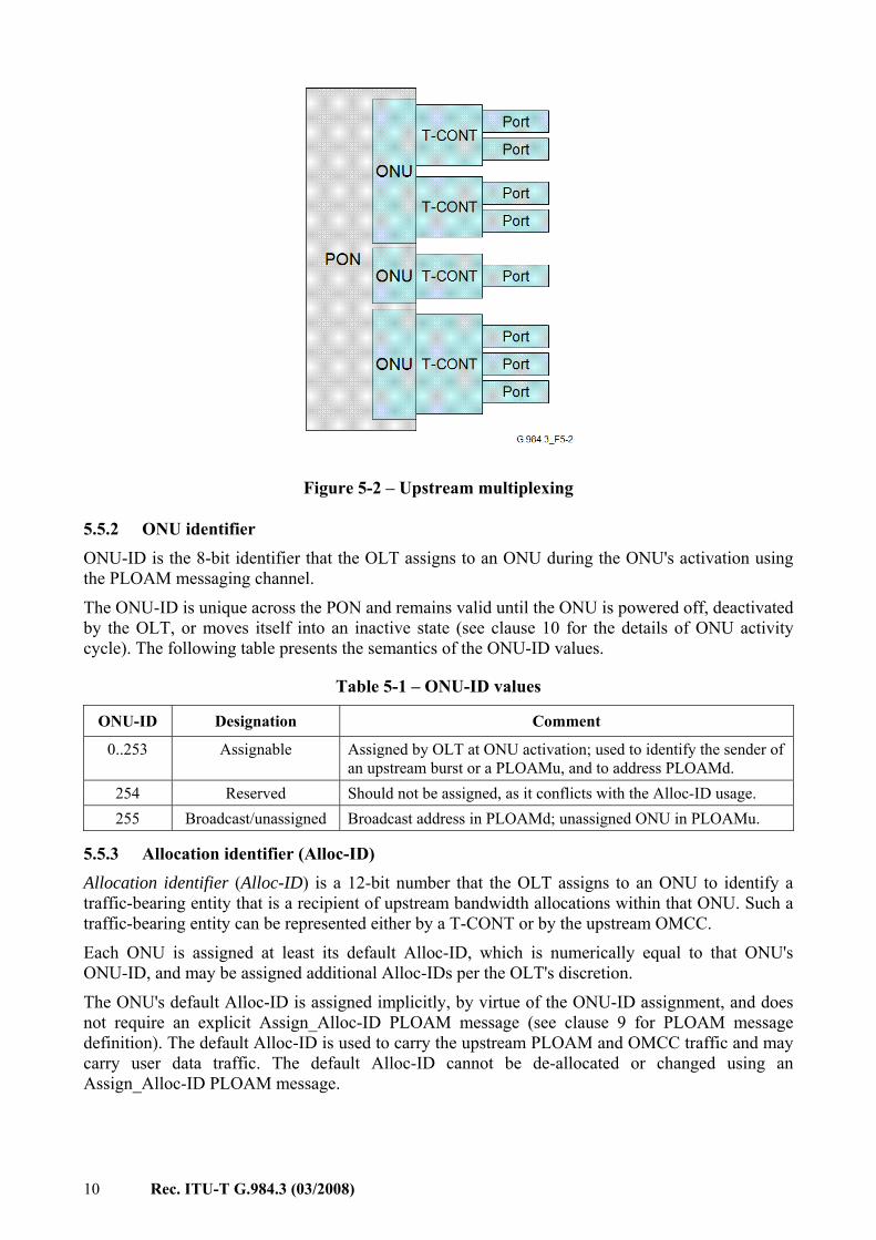
In the upstream direction, the traffic multiplexing functionality is distributed. The OLT grants upstream transmission opportunities, or upstream bandwidth allocations, to the traffic-bearing entities within the subtending ONUs. The ONU's traffic-bearing entities that are recipients of the upstream bandwidth allocations are identified by their allocation IDs (Alloc-IDs). The bandwidth allocations to different Alloc-IDs are multiplexed in time as specified by the OLT in the bandwidth maps transmitted downstream. Within each bandwidth allocation, the ONU uses the GEM Port-ID as a multiplexing key to identify the GEM frames that belong to different upstream logical connections.
10 Rec. ITU-T G.984.3 (03/2008)
Figure 5-2 – Upstream multiplexing
5.5.2 ONU identifier ONU-ID is the 8-bit identifier that the OLT assigns to an ONU during the ONU's activation using the PLOAM messaging channel.
The ONU-ID is unique across the PON and remains valid until the ONU is powered off, deactivated by the OLT, or moves itself into an inactive state (see clause 10 for the details of ONU activity cycle). The following table presents the semantics of the ONU-ID values.
Table 5-1 – ONU-ID values
ONU-ID Designation Comment
0..253 Assignable Assigned by OLT at ONU activation; used to identify the sender of an upstream burst or a PLOAMu, and to address PLOAMd.
254 Reserved Should not be assigned, as it conflicts with the Alloc-ID usage. 255 Broadcast/unassigned Broadcast address in PLOAMd; unassigned ONU in PLOAMu.
5.5.3 Allocation identifier (Alloc-ID) Allocation identifier (Alloc-ID) is a 12-bit number that the OLT assigns to an ONU to identify a traffic-bearing entity that is a recipient of upstream bandwidth allocations within that ONU. Such a traffic-bearing entity can be represented either by a T-CONT or by the upstream OMCC.
Each ONU is assigned at least its default Alloc-ID, which is numerically equal to that ONU's ONU-ID, and may be assigned additional Alloc-IDs per the OLT's discretion.
The ONU's default Alloc-ID is assigned implicitly, by virtue of the ONU-ID assignment, and does not require an explicit Assign_Alloc-ID PLOAM message (see clause 9 for PLOAM message definition). The default Alloc-ID is used to carry the upstream PLOAM and OMCC traffic and may carry user data traffic. The default Alloc-ID cannot be de-allocated or changed using an Assign_Alloc-ID PLOAM message.

Rec. ITU-T G.984.3 (03/2008) 11
Additional Alloc-IDs are assigned to the ONU explicitly by means of the Assign_Alloc-ID PLOAM message with Alloc-ID type 1. Such an assignment can be explicitly reversed by means of Assign_Alloc-ID PLOAM message with Alloc-ID type 255.
All Alloc-ID assignments, including the default Alloc-ID assignment, shall be lost upon ONU deactivation.
Table 5-2 – Alloc-ID values
Alloc-ID Designation Comment
0..253 Default Default Alloc-ID, which is implicitly assigned with and is equal to the ONU-ID.
254 Broadcast Used by OLT in a serial number request allocation structure to indicate that any ONU executing the serial number acquisition phase of the activation procedure may use this allocation to transmit a serial number response.
255 Unassigned May be used by the OLT to indicate that a particular allocation structure should not be used by any ONU.
256..4095 Assignable If more than a single Alloc-ID is needed for an ONU, the OLT assigns additional Alloc-IDs to that ONU by selecting a unique number from this range and communicating it to the ONU using the Assign_Alloc-ID PLOAM message.
5.5.4 Transmission container (T-CONT) A Transmission container (T-CONT) is an ONU object representing a group of logical connections that appear as a single entity for the purpose of upstream bandwidth assignment on the PON.
For a given ONU, the number of supported T-CONTs is fixed. The ONU autonomously creates all the supported T-CONT instances during ONU activation or upon OMCI MIB reset. The OLT uses the OMCC to discover the number of T-CONT instances supported by a given ONU and to manage those instances.
To activate a T-CONT instance for carrying the upstream user traffic, the OLT has to establish a mapping between the T-CONT instance and an Alloc-ID, which has been previously assigned to the given ONU via the PLOAM messaging channel. Mapping of T-CONTs to Alloc-IDs is performed via the OMCC.
The OMCC itself is mapped, in the upstream direction, to the default Alloc-ID. This mapping is fixed; it cannot be managed via the OMCI MIB and it should survive the OMCI MIB reset.
Any Alloc-ID assigned to the ONU, including the default Alloc-ID, can be associated with, at most, single-user traffic T-CONT. If the OLT attempts to map more than one user traffic T-CONT to an Alloc-ID, the ONU shall reject the second SET message as an error.
5.5.5 GEM port identifier
GEM port identifier, or GEM Port-ID, is a 12-bit number that is assigned by the OLT to the individual logical connections. The GEM Port-ID assignment to the OMCC logical connection is performed by means of Configure_Port-ID PLOAM message. All other GEM Port-ID assignments for the ONU are performed via the OMCC.
5.6 Disambiguation of the concept of frame
The term "frame" can appear within this Recommendation in the following contexts: 1) User frame: a service data unit (SDU) of the GTC layer, usually represented by an
Ethernet frame.

12 Rec. ITU-T G.984.3 (03/2008)
2) GEM frame: a protocol data unit (PDU) of the GTC framing sublayer that consists of a 5-byte GEM header and a variable-length GEM payload.
3) Downstream GTC frame: 125-µs interval with well-defined boundaries and fixed, repetitive data format containing the GTC header (PCBd field) and the GTC payload.
4) Upstream GTC frame: 125-µs interval with well-defined boundaries containing multiple upstream transmission bursts controlled by the individual BWmaps.
Every effort is made to ensure that each occurrence of the term is qualified appropriately to avoid confusion.
5.7 Concepts associated with upstream physical layer overhead The upstream direction, G-PON operates in the burst mode. The transmission bursts from different ONU transceivers require isolation and delineation at the OLT receiver.
A transmission burst is the interval during which the laser of an individual ONU transceiver remains turned on and is transmitting a pattern of zeros and ones into the optical fibre. Each burst contains the upstream physical layer overhead (PLOu) section and one or more allocation intervals.
The PLOu section is composed of preamble, delimiter and the burst header.
The burst header is 3 bytes long and is composed of BIP, ONU-ID and Ind fields.
Burst mode overhead is the sequence of time intervals with specified duration and transmission patterns that are required to maintain burst isolation and delineation and that remain invariant for all the ONUs on the PON for as long as the PON is operational. The burst mode overhead includes the guard time, preamble time and delimiter time. See [ITU-T G.984.2] for the allocation of burst mode overhead times.
Further details and illustrations of the upstream burst structure and overhead can be found in clause 8.2.
6 G-PON system architecture
6.1 Network architecture and reference configuration G-PON network architecture and reference configuration are described in clause 5 of [ITU-T G.984.1].
6.2 Parameters of the GTC layer This Recommendation covers the G-PON systems supporting the following raw transmission rates: – 1.24416 Gbit/s up, 2.48832 Gbit/s down. – 2.48832 Gbit/s up, 2.48832 Gbit/s down.
This Recommendation covers the G-PON systems supporting the fibre logical split ratio of up to 1:128, the differential fibre distance of up to 20 km, and logical reach in excess of 20 km. The exact logical reach requirement, which is out of scope of the GTC layer specification, can be found in [ITU-T G.984.1].
G-PON supports all services defined in [ITU-T G.984.1]. GTC supports the transport of the 8-kHz clock and, additionally, a 1-kHz reference signal provided by the OLT to the ONU using a control signal. The survivability function of G-PON that enhances the reliability of the access networks is available and is optional as described in [ITU-T G.984.1]. Therefore, the TC layer transports PON section trace (PST) information. Due to the multicast nature of the PON, downstream frames need some kind of security mechanism at the TC layer.

Rec. ITU-T G.984.3 (03/2008) 13
6.3 Functional blocks The G-PON system consists of three components: OLT, ONU and ODN. This clause provides guidelines for typical configuration for each component.
6.3.1 Optical line termination (OLT) The OLT is connected to the switched network via standardized interfaces. On the distribution side, it presents optical access interfaces according to this and other G-PON standards, in terms of bit rate, power budget, jitter, etc.
The OLT consists of three major parts: – service port interface function; – cross-connect function; – optical distribution network (ODN) interface.
The OLT major building blocks are described in the following clauses. Figure 6-1 depicts the typical OLT functional block diagram.
Figure 6-1 – OLT functional block diagram
1) PON core shell This block consists of two parts, the ODN interface function specified in [ITU-T G.984.2]
and the PON TC function specified in this Recommendation. PON TC function includes framing, media access control, OAM, DBA, delineation of protocol data unit (PDU) for the cross-connect function, and ONU management.
2) Cross-connect shell The cross-connect shell provides a communication path between the PON core shell and the
service shell. Technologies for connecting this path depend on services, internal architecture in OLT and other factors.
3) Service shell This shell provides translation between service interfaces and the TC frame interface of the
PON section.
14 Rec. ITU-T G.984.3 (03/2008)
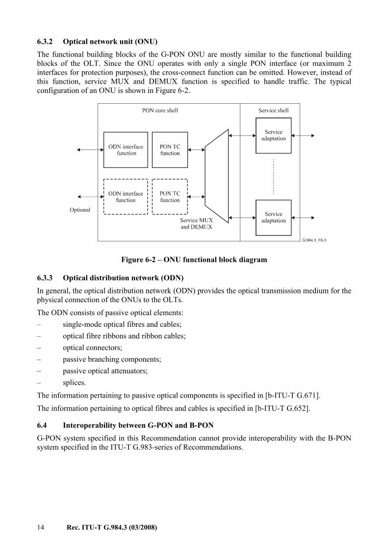
6.3.2 Optical network unit (ONU) The functional building blocks of the G-PON ONU are mostly similar to the functional building blocks of the OLT. Since the ONU operates with only a single PON interface (or maximum 2 interfaces for protection purposes), the cross-connect function can be omitted. However, instead of this function, service MUX and DEMUX function is specified to handle traffic. The typical configuration of an ONU is shown in Figure 6-2.
Figure 6-2 – ONU functional block diagram
6.3.3 Optical distribution network (ODN) In general, the optical distribution network (ODN) provides the optical transmission medium for the physical connection of the ONUs to the OLTs.
The ODN consists of passive optical elements: – single-mode optical fibres and cables; – optical fibre ribbons and ribbon cables; – optical connectors; – passive branching components; – passive optical attenuators; – splices.
The information pertaining to passive optical components is specified in [b-ITU-T G.671].
The information pertaining to optical fibres and cables is specified in [b-ITU-T G.652].
6.4 Interoperability between G-PON and B-PON
G-PON system specified in this Recommendation cannot provide interoperability with the B-PON system specified in the ITU-T G.983-series of Recommendations.

Rec. ITU-T G.984.3 (03/2008) 15
7 G-PON transmission convergence layer overview
7.1 GTC protocol stack
7.1.1 GTC sublayers This clause describes the transmission convergence layer architecture in the G-PON system. Figure 7-1 shows the protocol stack for the overall G-PON transmission convergence (GTC) layer. The GTC layer is comprised of two sublayers, the GTC framing sublayer and the GTC adaptation sublayer. From another point of view, GTC consists of a control and management plane (C/M-plane), which manages user traffic flows, security and OAM features, and a user data plane (U-plane) which carries user traffic. In the GTC framing sublayer, GEM section, Embedded OAM and PLOAM sections are recognized according to the location on a GTC frame. The embedded OAM is terminated at this sublayer for local control purposes, because information of embedded OAM is included in the GTC frame header directly. PLOAM information is processed at the PLOAM block located as a client of this sublayer. Service data units (SDUs) in GEM sections are converted from/to conventional GEM protocol data units (PDUs) at the GTC adaptation sublayer. Moreover, these GEM PDUs carry the OMCI channel data. The OMCI channel data is recognized at the adaptation sublayer and is interchanged from/to OMCI entity. Embedded OAM, PLOAM and OMCI are categorized into the C/M-plane. SDUs, except for OMCI over GEM, are categorized into the U-Plane.
The GTC framing sublayer has global visibility to all data transmitted, and the OLT GTC Framing sublayer is a direct peer of all the ONU GTC framing sublayers.
Moreover, the DBA control block is specified as a common functional block in the GTC adaptation sublayer.

16 Rec. ITU-T G.984.3 (03/2008)
Figure 7-1 – Protocol stack for the GTC
The remaining subclauses describe the architecture of C/M-plane and U-Plane, the relationship between these planes, functional features of GTC and operations focusing on GTC.
7.1.2 Protocol stack for the C/M-plane
The control and management plane in the GTC system consists of three parts: embedded OAM, PLOAM and OMCI. The embedded OAM and PLOAM channels manage the functions of the PMD and the GTC layers. The OMCI provides a uniform system for managing higher (service-defining) layers. Functional blocks in the C/M-plane are shown in Figure 7-2.
G-PON Transmission Convergence (GTC) Layer
G.984.3_F7-1
G-PON Physical Medium Dependent (PMD) Layer
PLOAM
GTC Framing Sublayer
GTC Adaptation Sublayer
GEM Adapter DBA Control
OMCI Adapter
OMCI GEM Client

Rec. ITU-T G.984.3 (03/2008) 17
Figure 7-2 – Functional blocks in the C/M-plane
The embedded OAM channel is provided by field-formatted information in the header of the GTC frame. This channel offers a low latency path for time-urgent control information, because each information piece is definitely mapped into a specific field in the header of the GTC frame. The functions that use this channel include: bandwidth allocation, security key switching, and dynamic bandwidth assignment signalling. The detailed description of this channel is provided in clause 8 as a part of the GTC frame specification.
The PLOAM channel is a message-formatted system carried in a dedicated space of the GTC frame. This channel is used for all other PMD and GTC management information that is not sent via the embedded OAM channel. The generic PLOAM message structure, message types and detailed format specifications are provided in clause 9.
The ONU management and control interface (OMCI) channel is used to manage the service-defining layers, which reside above the GTC, and is technically out of scope of this Recommendation. However, the GTC must provide a GEM-based transport interface for this
G.984.3_F7-2
GTC Framing Sublayer
PLOAM
GTC Adaptation Sublayer
GEM Adapter
OMCI Adapter
OMCI
Multiplexing based on location within frame
PLOAM Partition GEM Partition Frame Header
Alloc-ID Filter
Embedded OAM
Port-ID Filter

18 Rec. ITU-T G.984.3 (03/2008)
management traffic, including configuration of appropriate transport protocol flow identifiers (GEM Port-IDs). This Recommendation specifies a format and transfer mechanism for the OMCI channel. The detailed OMCI specification can be found in [b-ITU-T G.984.4].
7.1.3 Protocol stack for the U-plane Traffic flows in the U-plane are identified by their GEM Port-IDs and payload type, as shown in Figure 7-3. In addition, the concept of T-CONT originally introduced in the B-PON context in [ITU-T G.983.4] is employed. A T-CONT represents a group of traffic flows associated with an allocation ID and appearing as a single entity for the purpose of upstream bandwidth assignment on the PON. Bandwidth assignment and QoS control are performed in every T-CONT by fixed and dynamic methods.
Figure 7-3 – The U-plane protocol stack and identification by Port-ID
The operations are summarized as follows.
In the downstream direction, the GEM frames are carried in the GTC payload and arrive at all the ONUs. The ONU framing sublayer extracts the frames, and the GEM TC adapter filters the frames
G.984.3_F7-3
GTC Framing Sublayer
GTC Adaptation Sublayer
GEM Adapter
GEM Client
Multiplexing based on location within frame
PLOAM Partition GEM Partition Frame Header
Alloc-ID Filter
Port-ID and PTI Filter
GEM Service

Rec. ITU-T G.984.3 (03/2008) 19
based on their 12-bit Port-ID. Only frames with the appropriate Port-IDs are allowed through to the GEM client function.
In the upstream direction, the GEM traffic is carried over one or more T-CONTs. The OLT receives the transmission associated with the T-CONT and the frames are forwarded to the GEM TC adapter and then the GEM client.
7.2 GTC key functions This clause summarizes two important functions in GTC system.
7.2.1 Media access control GTC system provides media access control for upstream traffic. In the basic concept, downstream frames indicate permitted locations for upstream traffic in upstream GTC frames synchronized with downstream GTC frames. The media access control concept in the GTC system is illustrated in Figure 7-4.
The OLT sends pointers in the upstream bandwidth map (BWmap) field of the downstream physical control block (PCBd), and these pointers indicate the time at which each ONU may begin and end its upstream transmission. In this way, only one ONU can access the medium at any time, and there is no contention in normal operation. The pointers are given in units of bytes, allowing the OLT to control the medium at an effective static bandwidth granularity of 64 kbit/s. However, some implementations of the OLT may choose to set the values of the pointers at a larger granularity, and achieve fine bandwidth control via dynamic scheduling.
Figure 7-4 – GTC media access control concept
Note that Figure 7-4 shows the case where the pointers are transmitted in ascending order. The OLT is required to transmit all pointers to any single ONU in ascending order of start time. It is recommended that all pointers are transmitted in ascending order of start time
The use of PCBd for media access control is described in detail in clause 8.1.3.

20 Rec. ITU-T G.984.3 (03/2008)
7.2.2 ONU registration The ONU registration is done in the auto-discovery procedure. There are two methods for ONU registration. In case of Configured-SN, the serial number of the ONU is registered at the OLT by the management system (e.g., NMS and/or EMS). In case of Discovered-SN, the serial number of the ONU is not registered at the OLT by the management system.
The details and best practices of ONU registration will be addressed in a separate amendment to this Recommendation.
7.3 Functions of Sublayers in GTC
7.3.1 Overview of GTC framing sublayer GTC framing sublayer has three functionalities as follows: 1) Multiplexing and demultiplexing PLOAM and GTC payload sections are multiplexed into a downstream GTC frame per the
specified frame format. In the upstream direction, each section is extracted from an upstream burst according to the BWmap corresponding to the upstream GTC frame to which the burst belongs. See clause 8 for the downstream and upstream GTC frame format specification.
2) Header creation and decoding GTC frame header is created and is formatted in a downstream frame. Upstream burst
header is decoded. Moreover, Embedded OAM is performed. 3) Internal routing function based on Alloc-ID Routing based on Alloc-ID is performed for data from/to the GEM TC adapter.
7.3.2 Overview of GTC adaptation sublayer and interface for upper entities Adaptation sublayer provides two TC adapters, i.e., the GEM TC adapter and OMCI adapter. The GEM TC adapter delineates GEM PDUs from the GTC payload section on the GTC framing sublayer and maps GEM PDUs into the GTC payload.
The GEM TC adapter can be configured to adapt these PDUs into a variety of upper layer transport interfaces.
Moreover, these adapters recognize the OMCI channel according to specific GEM Port-ID. The OMCI adapter can exchange OMCI channel data for the GEM TC adapter. The OMCI adapter accepts data from GEM TC adapter and transfers it to the OMCI entity. On the other hand, it transfers data from the OMCI entity to the GEM TC adapter.
7.3.3 Overview of PLOAM The GTC framing sublayer provides an interface for the interchange of PLOAM messages. The PLOAM messages are defined in clause 9.
7.4 Dynamic bandwidth assignment Dynamic bandwidth assignment (DBA) in gigabit-capable passive optical networks (G-PON) is the process by which the optical line terminal (OLT) reallocates the upstream transmission opportunities to the traffic-bearing entities within optical network units (ONUs) based on the dynamic indication of their activity status and their configured traffic contracts. The activity status indication can be either explicit through buffer status reporting, or implicit through transmission of idle GEM frames in place of granted upstream transmission opportunities.
In comparison with static bandwidth assignment, the DBA mechanism improves the G-PON upstream bandwidth utilization by reacting adaptively to the ONUs bursty traffic patterns. The
Rec. ITU-T G.984.3 (03/2008) 21
practical benefits of DBA are twofold. First, the network operators can add more subscribers to the PON due to more efficient bandwidth use. Second, the subscribers can enjoy enhanced services, such as those requiring variable rate with the peaks extending beyond the levels that can reasonably be allocated in a static fashion.
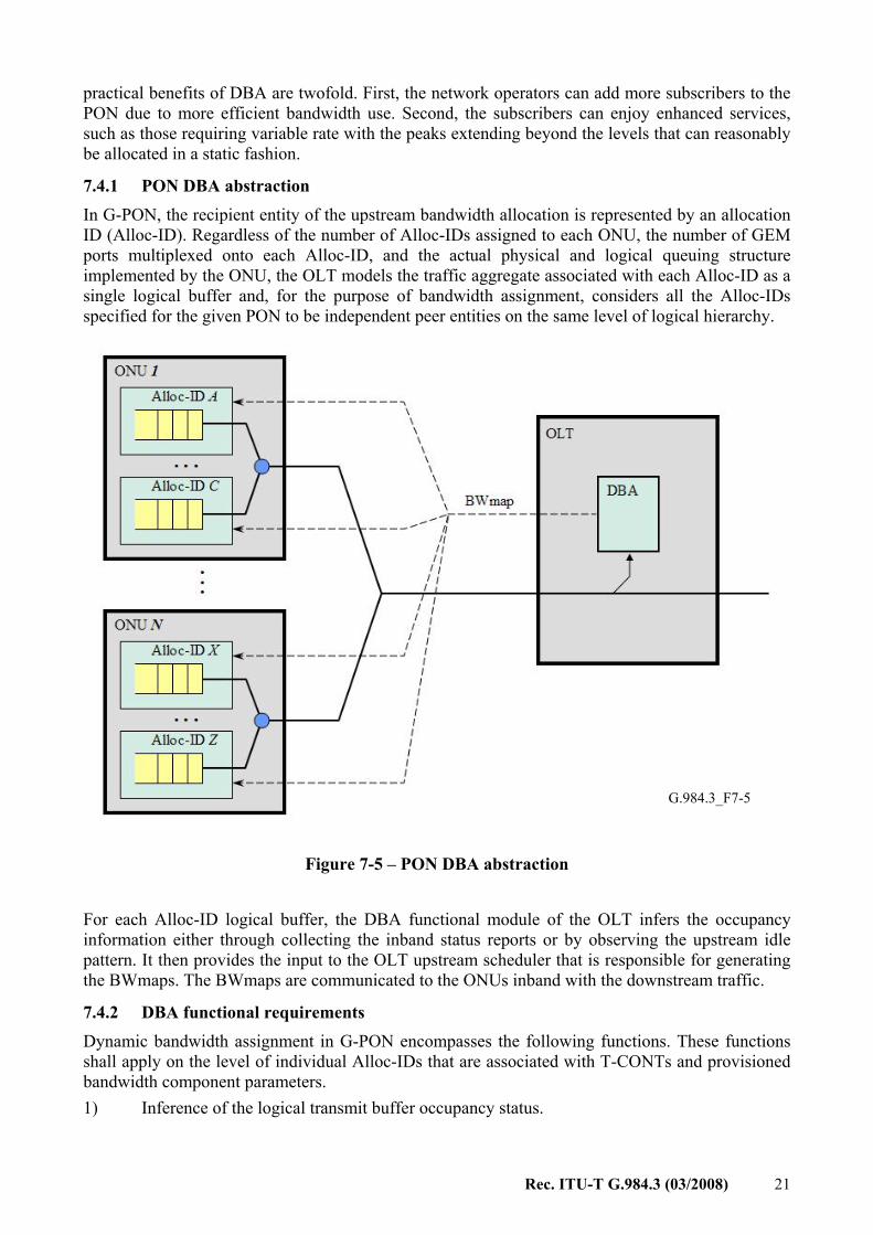
7.4.1 PON DBA abstraction In G-PON, the recipient entity of the upstream bandwidth allocation is represented by an allocation ID (Alloc-ID). Regardless of the number of Alloc-IDs assigned to each ONU, the number of GEM ports multiplexed onto each Alloc-ID, and the actual physical and logical queuing structure implemented by the ONU, the OLT models the traffic aggregate associated with each Alloc-ID as a single logical buffer and, for the purpose of bandwidth assignment, considers all the Alloc-IDs specified for the given PON to be independent peer entities on the same level of logical hierarchy.
Figure 7-5 – PON DBA abstraction
For each Alloc-ID logical buffer, the DBA functional module of the OLT infers the occupancy information either through collecting the inband status reports or by observing the upstream idle pattern. It then provides the input to the OLT upstream scheduler that is responsible for generating the BWmaps. The BWmaps are communicated to the ONUs inband with the downstream traffic.
7.4.2 DBA functional requirements Dynamic bandwidth assignment in G-PON encompasses the following functions. These functions shall apply on the level of individual Alloc-IDs that are associated with T-CONTs and provisioned bandwidth component parameters. 1) Inference of the logical transmit buffer occupancy status.
G.984.3_F7-5

22 Rec. ITU-T G.984.3 (03/2008)
2) Update of the instantaneously assigned bandwidth according to the inferred buffer occupancy status within the provisioned bandwidth component parameters.
3) Issue of allocations according to the updated instantaneous bandwidth. 4) Management of the DBA operations.
The G-PON OLT is required to support DBA.
7.4.3 DBA methods Depending on the ONU buffer occupancy inference mechanism, two DBA methods can be distinguished: – Status reporting (SR) DBA is based on the explicit buffer occupancy reports that are
solicited by the OLT and submitted by the ONUs in response; – Traffic monitoring (TM) DBA is based on the OLT's observation of the idle GEM frame
pattern and its comparison with the corresponding bandwidth maps.
The OLT should support a combination of both TM and SR DBA methods and be capable of accommodating on the same PON a mix of status-reporting and non-status-reporting ONUs, performing the DBA functions of clause 7.4.2 in an efficient and fair manner. The specific efficiency and fairness criteria can be based on the overall PON utilization, the individual ONU's performance tested against the corresponding objectives, and the comparative performance tested for multiple ONUs.
While for an ONU the support of DBA status reporting is optional, the ONUs that do not report the buffer status shall still be capable of parsing the DBA report requests and filling the upstream fields with an invalid code, thus preserving the proper data delineation.
The status reporting DBA method involves in-band signalling between the OLT and the ONUs, which is an inherent part of the G-PON TC specification. The SR DBA signalling is discussed in detail in clause 8.4.
On the other hand, the algorithmic details of how the OLT applies the reported status information, the entire specification of the traffic monitoring DBA method, as well as the details of the OLT upstream scheduler, which is responsible for the BWmap generation, are outside the G-PON TC layer scope, and their implementation is left to the OLT vendors.
7.4.4 Mathematical model of dynamic bandwidth assignment
This clause presents a formal bandwidth assignment model that specifies the target behaviour of the DBA mechanism. It is a fluid reference model (that is, it assumes continuous, infinitely divisible traffic flows) that can be used to develop the test cases to evaluate a DBA implementation, but cannot and should not be viewed as a specification of the implementation itself.
7.4.4.1 Summary of notation The following notation is employed throughout this clause:
C the upstream capacity of the PON interface, which is equal to the nominal interface rate less framing overhead and PLOAM allowance [bit/s].
A The amount of traffic arriving to a buffer [b].
B Logical buffer occupancy [b].
D Allocation traffic descriptor.
RF Fixed bandwidth, provisioned [bit/s].
RA Assured bandwidth, provisioned [bit/s].

Rec. ITU-T G.984.3 (03/2008) 23
RM Maximum bandwidth, provisioned [bit/s]. RG Guaranteed bandwidth, dynamic [bit/s].
RL Offered traffic load, dynamic [bit/s].
RNA Non-assured bandwidth, dynamic [bit/s].
RBE Best-effort bandwidth, dynamic [bit/s].
SNA Surplus bandwidth for non-assured bandwidth assignment, dynamic [bit/s].
SBE Surplus bandwidth for best-effort bandwidth assignment, dynamic [bit/s]. χAB Ternary eligibility indicator for additional bandwidth assignment: {None, NA, BE}.
P Priority for best-effort bandwidth assignment.
ω Weight for best-effort bandwidth assignment.
Where appropriate, a superscript indicates a specific Alloc-ID.
7.4.4.2 Offered traffic load Each Alloc-ID can be dynamically characterized by its offered traffic load, RL(t), which is defined as the average rate at which the logical buffer of an Alloc-ID would have to be serviced in order to be drained in certain fixed time ∆, representing a system constant (equal to at least one, but more practically, eight-frame times):
Δ
Δ++= ),()()( ttAtBtRL (7-1)
where B(t) is the logical buffer occupancy at time t, and the optional term A(t, t + ∆) represents the new arrivals to the buffer during the interval (t, t + ∆). Note that A(t, t + ∆) may be excluded from the definition if strictly non-predictive reference is desired.
7.4.4.3 Traffic descriptor Each Alloc-ID is provisioned with a traffic descriptor that specifies the three bandwidth component parameters: fixed bandwidth, assured bandwidth, and maximum bandwidth, as well as the ternary eligibility indicator for additional bandwidth assignment: Non-assured sharing, best-effort sharing, or none. Thus the traffic descriptor of Alloc-ID i may be formally represented as a four-tuple:
iAB
iM
iA
iF
i RRRD χ= ,,, (7-2)
Note that the term "bandwidth" is used herein as an equivalent of data rate to denote a portion of G-PON uplink capacity which can be allocated in a specific manner.
Fixed bandwidth, RF ≥ 0, represents the reserved portion of the uplink capacity that the OLT statically allocates to the given Alloc-ID, regardless of its individual traffic demand and the overall traffic load on the PON.
Assured bandwidth, RA ≥ 0, represents a portion of the uplink capacity that the OLT is expected to allocate to the given Alloc-IDs as long as the Alloc-ID has unsatisfied traffic demand, regardless of the overall traffic load on the PON. If the traffic demand is satisfied, the OLT may fully or partially reassign this bandwidth portion to the other eligible Alloc-IDs.
Maximum bandwidth, RM > 0, represents the upper limit on the total bandwidth that can be allocated to the given Alloc-ID under any traffic conditions.

24 Rec. ITU-T G.984.3 (03/2008)
A correctly formed traffic descriptor should satisfy the following three invariant restrictions:
iA
iF
iM RRR +≥
0ifonly, >+>=χ iA
iF
iM
iAB RRRNA (7-3)
0ifonly, ≥+>=χ iA
iF
iM
iAB RRRBE
In addition, the overall traffic specification should satisfy the basic stability condition:
( ) CRRi
iA
iF ≤+∑ (7-4)
where summation is over the set of all Alloc-IDs on the PON, and C is the capacity of the upstream interface.
7.4.4.4 Components of assigned bandwidth
The bandwidth Ri(t) ≥ 0, dynamically assigned to an Alloc-ID under the present reference model is composed of the guaranteed and additional components. The additional bandwidth may be either in non-assured or best-effort form:
)()()( tRtRtR iNA
iG
i += (7-5a)
for the Alloc-IDs with χiAB = NA, and
)()()( tRtRtR iBE
iG
i += (7-5b)
for the Alloc-IDs with χiAB = BE.
7.4.4.5 Guaranteed bandwidth assignment As long as the basic stability condition (equation 7-4) is satisfied, the guaranteed component of the dynamically assigned bandwidth is given by:
{ }{ })(;max;min)( tRRRRtR iL
iF
iA
iF
iG += (7-6)
and is available to the given Alloc-ID regardless of the overall traffic load conditions. Thus, RiF
represents the lower bound on assigned guaranteed bandwidth RiG(t), and Ri
A + RiF is the upper
bound.

Rec. ITU-T G.984.3 (03/2008) 25
Figure 7-6 – Variants of bandwidth assignment for different offered loads
7.4.4.6 Non-assured bandwidth assignment Non-assured bandwidth, RNA, is a form of additional bandwidth that the OLT may dynamically assign to an eligible Alloc-ID in proportion to the sum of that Alloc-ID's fixed and assured bandwidths.
The amount of surplus bandwidth that can participate in the non-assured bandwidth assignment is equal to the portion of the uplink capacity that remains available after the guaranteed bandwidth components have been dynamically assigned for all the Alloc-IDs. This amount is given by the following expression:
{ }{ }∑ +−=i
iL
iF
iA
iFNA tRRRRCtS )(;max;min)( (7-7)
The fairness criterion for non-assured bandwidth sharing is given below. Under the specific traffic load conditions, any two eligible (χAB = NA), unsaturated (RG (t) + RNA(t) < min{RM ; RL(t)}) Alloc-IDs i and j shall be assigned the Non-assured bandwidths that ideally satisfy the condition:
jA
jF
jNA
iA
iF
iNA
RR
tR
RRtR
+=
+
)()( (7-8)
For an eligible Alloc-ID whose non-assured fair share is calculated according to criterion (equation 7-8) results in saturation (RG (t) + RNA(t) ≥ min{RM ; RL(t)}), the dynamically assigned bandwidth shall satisfy the condition: R(t) = min{RM ; RL(t)}.
G.984.3_F7-6

26 Rec. ITU-T G.984.3 (03/2008)
7.4.4.7 Best-effort bandwidth assignment Best-effort bandwidth is a form of additional bandwidth that the OLT may dynamically assign to an eligible Alloc-ID in proportion to the non-guaranteed portion of that Alloc-ID's provisioned maximum bandwidth.
The amount of surplus bandwidth that can participate in the best-effort bandwidth assignment is equal to the portion of the uplink capacity that remains available after the guaranteed bandwidth and non-assured bandwidth components have been assigned appropriately. This amount is given by the following expression:
{ }{ }{ }∑
=∈
−=NAi
iL
iF
imBE
iAB
tRRRCtSχ
)(;max;min)(
{ }{ }{ }∑
≠∈
+−NAi
iL
iF
iA
iF
iAB
tRRRRχ
)(;max;min (7-9)
The fairness criterion for Best-effort bandwidth sharing is formulated as follows. Under the specific traffic load conditions, any two eligible (χAB = BE), unsaturated (RG(t) + RBE(t) < min{RM ; RL(t)}) Alloc-IDs i and j shall be assigned the Best-effort bandwidths that ideally satisfy the condition:
( ) ( )jA
jF
jM
jBE
iA
iF
iM
iBE
RRR
tR
RRRtR
+−=
+−
)()( (7-10)
For an eligible Alloc-ID whose best-effort fair share is calculated according to criterion equation 7-10 results in saturation (RG (t) + RBE(t) ≥ min{RM ; RL(t)}), the dynamically assigned bandwidth shall satisfy the condition: R(t) = min{RM ; RL(t)}.
7.4.4.8 Prioritization of assigned bandwidth components The bandwidth assignment model described herein effectively introduces a strict priority hierarchy of the assigned bandwidth components: 1) Fixed bandwidth (highest priority). 2) Assured bandwidth. 3) Non-assured bandwidth. 4) Best-effort bandwidth (lowest priority).
First, the OLT should assign the fixed bandwidth to all the Alloc-IDs on the PON, regardless of their individual offered loads and the overall traffic conditions. Then the OLT completes the guaranteed bandwidth component assignment by allocating the assured bandwidth to the Alloc-IDs until either the respective provisioned level RA is reached or the traffic demand is satisfied. After that, the OLT allocates the non-assured bandwidth components to the eligible unsaturated Alloc-IDs until either all the Alloc-IDs reach their saturation level (that is, the lesser of the respective maximum bandwidth RM, and offered load RL(t)), or the surplus bandwidth pool SNA(t), is exhausted. Finally, the OLT allocates the best-effort bandwidth components to the eligible unsaturated Alloc-IDs.
7.4.5 Extended bandwidth assignment model The OLT may optionally provision Alloc-IDs using an extended traffic descriptor:
iiiAB
iM
iA
iF
i PRRRD ωχ= ,,,,, (7-11)

Rec. ITU-T G.984.3 (03/2008) 27
In comparison with equation 7-2, the extended traffic descriptor employs two additional parameters: the best-effort priority Pi and the best-effort weight ωi which are applicable in case χAB = BE. The best-effort fairness criterion employs both these parameters and is formulated as follows: 1) As long as at least one eligible Alloc-ID (χAB = BE) with a higher best-effort priority
remains unsaturated (RG(t) + RBE(t) < min{RM ; RL(t)}), the assigned best-effort bandwidth share of any Alloc-ID with the given priority Pi shall be zero.
2) If no eligible Alloc-ID with a higher best-effort priority remains unsaturated, any two eligible (χAB = BE), unsaturated (RG(t) + RBE(t) < min{RM ; RL(t)}) Alloc-IDs i and j with the given priority shall be assigned the best-effort bandwidths that ideally satisfy the condition:
j
tRtR jBE
i
iBE
ω=
ω)()( (7-12)
The extended DBA bandwidth assignment model can be reduced to the conventional model of clause 7.4.4 by assigning all the Alloc-IDs involved to the same priority class, and choosing weights ωi in proportion to ( )( )i
AiF
iM RRR +− . In addition, the extended model allows to specify the desired
behaviour of a system where multiple Alloc-IDs within each ONU correspond to prioritized classes of service, and the Alloc-IDs within the same priority class across the PON are serviced on a weight-proportional basis.
For example, one of the realizable architectures is shown in Figure 7-7, where all the T-CONTs are assumed to be best-effort (χAB = BE) and are provisioned with the BE priorities Pi and the BE weights ωi .
Figure 7-7 – An example of a queuing and scheduling architecture that can be specified under the extended bandwidth assignment model
G.984.3_F7-7

28 Rec. ITU-T G.984.3 (03/2008)
7.4.6 Alloc-ID traffic descriptors and T-CONT types In general, the bandwidth and eligibility components of the Alloc-ID traffic descriptor may have different interrelations with each other. The five combinations of Alloc-ID traffic descriptor parameters that, in practical terms, appear more important than the others are identified and associated with the specific T-CONT types. The definition of the five T-CONT types is given in Table 7-1 (only non-zero components are shown).
Table 7-1 – T-CONT type summary
Traffic descriptor component Type 1 Type 2 Type 3 Type 4 Type 5
Fixed BW RF RF Assured BW RA RA RA Maximum BW RM = RF RM = RA RM > RA RM RM ≥ RF + RA Additional BW eligibility None None NA BE Any
T-CONT type 1 is characterized by the fixed bandwidth component only, and is not eligible to share surplus bandwidth. It is suitable for carrying fixed-rate (or variable-rate with relatively low rate bound) traffic which is sensitive to delay and jitter.
T-CONT type 2 is characterized by the assured bandwidth only, and is not eligible to share surplus bandwidth. It is suitable for carrying on-off type traffic with well-defined rate bound which does not have strict delay and jitter requirements.
T-CONT type 3 is characterized by assured bandwidth and eligibility to participate in non-assured bandwidth sharing. It is suitable for carrying variable-rate bursty traffic which requires average rate guarantee.
T-CONT type 4 is characterized by eligibility to share the Best-effort bandwidth with neither fixed nor assured bandwidth provisions. It is suitable for carrying variable-rate bursty traffic which does not exhibit delay sensitivity.
Finally, T-CONT type 5 is a consolidation of other T-CONT types which can be applied to most general traffic flows.
The concept of T-CONT type is introduced as a matter of convenience only to simplify the referencing of certain, most common Alloc-ID traffic descriptors. The value of T-CONT type is not encoded, is not exposed on the PON interface, and is not communicated to the ONU. The G-PON access system handles Alloc-IDs based on the provisioned traffic descriptor parameters, and not based on the T-CONT type.
7.4.7 DBA performance requirements
In practice, the OLT DBA algorithm does not have the complete knowledge of the system state. In
particular, instead of the true offered loads, ),(tRiL it operates on the basis of the estimates, ),(ˆ tRi
L that can be obtained from the DBRu reports and traffic monitoring results by the methods outside of the standardization scope. This clause recommends several DBA performance criteria that allow to evaluate a practical DBA implementation against the reference model of clause 7.4.4 and, if applicable, against the optional extended reference model of clause 7.4.5.
7.4.7.1 Stationary bandwidth assignment
Definition In a system where Alloc-ID activity and traffic demand status remain constant, the assigned bandwidth to Alloc-ID is measured as an average over the BWmaps transmitted in any sequence of
Rec. ITU-T G.984.3 (03/2008) 29
K consecutive downstream frames, where K is chosen large enough to average the allocations that may vary from frame to frame.
Target performance The OLT DBA algorithm shall ensure that the stationary assigned bandwidth for each subtending unsaturated Alloc-ID is at least equal to the respective fixed plus assured bandwidth and is within the specified bounds (e.g., 10%) of the dynamic value computed based on the reference model of clause 7.4.4 and, if applicable, the optional extended reference model of clause 7.4.5.
7.4.7.2 Assured bandwidth restoration time
Definition This is the worst-case time interval, as observed at the ONU, from the moment an Alloc-ID, which is entitled to receive assured bandwidth assignment but has not been receiving it due to insufficient traffic demand, increases the traffic demand to at least its fixed plus assured level, to the moment it is granted the full provisioned assured bandwidth in addition to the fixed bandwidth. The ending moment of the interval is more precisely defined as the start of the first upstream frame in a sequence of K consecutive frames, sufficiently large to average the frame-to-frame variations, over which the average bandwidth allocated to the Alloc-ID meets the specified condition.
Target performance A few milliseconds shall be required (target of 2 ms).
7.4.7.3 DBA convergence time
Definition
This is the worst-case time interval from the moment of a single activity status or traffic load change event at any ONU in the previously stationary system, to the moment the OLT adjusts its bandwidth assignments for all the subtending unsaturated ONUs to the levels that are at least equal to the respective fixed plus assured bandwidths and are within the specified bounds (e.g., 20%) of the respective dynamic values computed based on the reference model of clause 7.4.4 and, if applicable, the optional extended reference model of clause 7.4.5. The ending moment of the interval is more precisely defined as the start of the first downstream frame in a sequence of K consecutive frames, sufficiently large to average the frame-to-frame variations, in which the transmitted BWmaps contain bandwidth allocations satisfying the specified condition on average.
Target performance
Ten milliseconds shall be required (target of 6 ms).
7.5 Resource allocation and quality of service (QoS)
A service specification, or traffic descriptor, shall be associated with each traffic flow mapped to a specific GEM Port-ID. The service specification is a set of service attributes characterizing type of service, contracted traffic flow parameters and the quality of service (QoS) objectives. The flow service specification typically includes at least committed information rate (CIR) and peak information rate (PIR).
In the downstream direction, it is the responsibility of the OLT to provide QoS-aware traffic management (including, as applicable, traffic policing, buffer management, scheduling and shaping) of GEM Port-ID traffic flows based on the respective service specifications, the availability of memory and bandwidth resources, and the dynamic traffic conditions.
In the upstream direction, an aggregate service specification is constructed for each T-CONT based on the service specifications of the GEM Port-ID flows multiplexed onto that T-CONT. The sum of the fixed and assured bandwidth components of the T-CONT's traffic descriptor should be not less

30 Rec. ITU-T G.984.3 (03/2008)
than (and typically equal to) the sum of the CIRs of the constituent flows. The maximum bandwidth of the T-CONT's traffic descriptor should be not less than the largest of the PIRs of the constituent flows and not more than the sum of the PIRs of the constituent flows. It is the responsibility of the OLT to provide QoS-aware traffic management of the aggregate traffic flows associated with the T-CONTs based on the respective aggregate service specifications, the upstream bandwidth availability and, possibly, the information obtained through upstream traffic monitoring and/or ONU status reporting. For each individual T-CONT, it is the responsibility of the ONT to which the T-CONT belongs to provide QoS-aware traffic management of the constituent GEM Port-ID traffic flows based on the respective GEM Port-ID service specifications, the resource availability and the dynamic traffic conditions.
The ONU upstream traffic management facilities supporting resource allocation and QoS may include ingress policing per GEM port, traffic shaping per GEM port, scheduling per T-CONT, traffic shaping per T-CONT.
8 GTC layer framing
Figure 8-1 shows the GTC frame structure for downstream and upstream directions. The downstream GTC frame consists of the physical control block downstream (PCBd) and the GTC payload section. The upstream GTC frame contains multiple transmission bursts. Each upstream burst consists of the upstream physical layer overhead (PLOu) section and one or more bandwidth allocation interval(s) associated with a specific Alloc-ID.
The downstream GTC frame provides the common time reference for the PON and the common control signalling for the upstream.
Figure 8-1 – GTC layer framing
8.1 Downstream GTC frame structure
A diagram of the downstream GTC frame structure is shown in Figure 8-2. The frame has a duration of 125 μs and is 38880 bytes long, which corresponds to the downstream data rate of 2.48832 Gbit/s. The PCBd length range depends on the number of allocation structures per frame.

Rec. ITU-T G.984.3 (03/2008) 31
Figure 8-2 – Downstream GTC frame
8.1.1 Bit and byte order Throughout this Recommendation, the convention is that the transmission order of all fields will be most significant bit first. For example, the number 0xF0 indicates the sequence beginning with one, and ending with zero.
8.1.2 Scrambling of the downstream GTC frame The downstream GTC frame is scrambled using a frame-synchronous scrambling polynomial. The polynomial used is x7+x6+1. This pattern is added modulo two to the downstream data. The shift register used to calculate this polynomial is reset to all-ones at the first bit following the PSync field of the PCBd, and is allowed to run until the last bit of the frame.
8.1.3 Physical control block downstream (PCBd) A diagram of the PCBd is shown in Figure 8-3. The PCBd contains several fields, each of which is described subsequently. The OLT sends the PCBd in a broadcast manner, and every ONU receives the entire PCBd. The ONUs then act upon the relevant information contained therein.
Figure 8-3 – GTC physical control block downstream (PCBd)
8.1.3.1 Physical synchronization (PSync) field The physical synchronization field is a fixed 32-bit pattern that begins every PCBd. The ONU logic can use this pattern to find the beginning of the frame. The coding of the PSync field is 0xB6AB31E0. Note that the PSync field is not scrambled.

32 Rec. ITU-T G.984.3 (03/2008)
The ONU implements a synchronization state machine as shown in Figure 8-4. The ONU begins in the Hunt state. The ONU searches for the PSync pattern in all possible alignments (both bit and byte) while in the Hunt state. Once a correct PSync pattern is found, the ONU transitions into the Pre-sync state and sets a counter, N, to value 1. The ONU then looks for another PSync pattern that follows the last one by 125 µs. For every correct PSync field, the counter is incremented. If an incorrect PSync field is found, the ONU transitions back to the Hunt state. In the Pre-sync state, if the counter ever equals M 1, the ONU transitions forward into the Sync state. Once the ONU reaches the Sync state, the ONU can declare that it has found the downstream GTC frame structure, and begin to process the PCBd information. If the ONU in the Sync state detects M2 consecutive incorrect PSync fields, then it can declare that it has lost downstream GTC frame alignment, and it transitions back to the Hunt state.
The recommended value for M 1 is 2. The recommended value for M 2 is 5.
Figure 8-4 – GTC downstream ONU synchronization state machine
8.1.3.2 Ident field The 4-byte Ident field is used to indicate larger framing structures. It contains the superframe counter which is employed by the encryption system, and may also be used to provide lower rate synchronous reference signals. The least significant 30 bits of the Ident field contain a counter, and each GTC frame's counter will be one larger than the previous one. Whenever the counter reaches its maximum value, it is set to 0 on the following GTC frame.
To provide error tolerance, the ONU must implement a local superframe counter, and a superframe synchronization state machine. This state machine is identical to the synchronization state machine described above. When in the Hunt state, the ONU loads the superframe counter received in the Ident field into its local counter. When in the Pre-sync and Sync states, the ONU compares its local value with the received counter value. A match indicates correct synchronization, while a mismatch indicates either a transmission error or desynchronization.
The most significant 1 bit of the Ident field is used to indicate whether FEC is being used in the downstream. The remaining bit of the Ident field is reserved. Figure 8-5 illustrates the Ident field.

Rec. ITU-T G.984.3 (03/2008) 33
Figure 8-5 – Ident field
8.1.3.3 PLOAMd field The PLOAM downstream field is a 13-byte field that contains the PLOAM message. The format of these messages is given in clause 9.
8.1.3.4 BIP field The BIP field is an 8-bit field that contains the bit-interleaved parity of all bytes transmitted since the last BIP, excluding FEC parity (if present). The receiver shall compute the bit interleaved parity on all bytes received since the last BIP, excluding the FEC parity (if present) and after FEC correction has been applied (if supported), and compare its result to the BIP transmitted in order to measure the number of errors on the link.
8.1.3.5 PLend field The payload length downstream field specifies the length of the Bandwidth map and the deprecated ATM partition. This field is sent twice for error robustness, and the procedure for insuring this robustness is given below.
The length of the bandwidth map (Blen) is given by the first 12 bits. This limits the number of allocations that may be granted in any 125-µs time duration to 4095. The actual length of the BWmap is 8*Blen bytes.
The length of the ATM partition (Alen) is given by the next 12 bits of the PLend field. The Alen field should contain all zeros.
The last 8 bits of the PLend field consist of a CRC-8, using the same polynomial as in [ITU-T I.432.1] (g(x) = x8 + x2 + x + 1). Unlike [ITU-T I.432.1], however, the CRC is not exclusive OR'ed with 0x55. The receiver of the PLend field will implement the error detecting and correcting functions of the CRC-8. The receiver will attempt to decode both copies of the PLend field sent and, depending on the outcome of the CRC-8 detection process, it will use the PLend field of the highest quality. For this purpose, the quality ranking from highest to lowest will be "error-free", "correctible single error" and "uncorrectable error". In the case where both PLend fields are uncorrectable, or are of the same quality but have different values, the receiver cannot parse the GTC frame as there is likely to be an undetectable combination of errors. With the dual transmission, the minimum number of errors that would cause this to occur is four bit errors.
Figure 8-6 depicts the PLend field.

34 Rec. ITU-T G.984.3 (03/2008)
Figure 8-6 – PLend field
8.1.3.6 BWmap fields The bandwidth map (BWmap) is a scalar array of 8-byte allocation structures. Each entry in this array represents a single bandwidth allocation to a particular T-CONT. The number of entries in the map is given in the PLend field. The format of each entry is given below and is shown in Figure 8-7.
Figure 8-7 – GTC bandwidth map allocation structure
The OLT is required to transmit all pointers to any single ONU in ascending order of start time. It is recommended that all pointers are transmitted in ascending order of start time. ONUs should be able to support up to eight allocation structures in any single BWmap and, optionally, could support more. Further, the maximum BWmap size limitation of an ONU should be at least 256 allocation structures, with larger BWmaps optionally supported.
8.1.3.6.1 Allocation ID field The Allocation ID field contains the 12-bit number that indicates the recipient of the bandwidth allocation, i.e., a particular T-CONT or an upstream OMCC within an ONU. The 12-bit field is generally unstructured, but a few conventions apply. First, the lowest 254 allocation ID values are

Rec. ITU-T G.984.3 (03/2008) 35
used to address the ONU directly. During the ranging procedure, the first Alloc-ID given to the ONU should be in this range. The first Alloc-ID given to the ONU is referred to as the default allocation ID. This Alloc-ID number is the same as the ONU-ID number (used in the PLOAM messages). It is used to carry PLOAM and OMCI traffic and, optionally, user traffic. If further Alloc-ID values are needed for that ONU, they should be taken from those above 255. Also, the Alloc-ID = 254 is the ONU activation Alloc-ID – used to discover unknown ONUs, and the Alloc-ID = 255 is the unassigned Alloc-ID. This is used to indicate that no T-CONT can use the associated allocation structure.
8.1.3.6.2 Flags field The Flags field is a 12-bit field that contains 4 separate indications that control certain functions of the associated upstream transmission. The meaning of these indications is as follows: – Bit 11 (MSB): Send power levelling sequence (PLSu): The PLSu feature is deprecated. Bit
11 should always be set to 0. – Bit 10: Send PLOAMu: If this bit is set, the ONU shall send its PLOAMu information
during this allocation. If this bit is not set, the ONU will not send the PLOAMu information in this allocation.
– Bit 9: Use FEC: If this bit is set, the ONU shall compute and insert FEC parity during this allocation. Note that this bit should be the same for the life of the allocation ID, and is merely an in-band confirmation of previously known data.
– Bits 8 and 7: Send DBRu (mode): Depending on the contents of these two bits, the ONU will send the DBRu corresponding to the allocation ID or not. The code points defined are:
00: Do not send DBRu at all. 01: Send the "Mode 0" DBRu (two bytes). 10: Send the "Mode 1" DBRu (three bytes). 11: Reserved, protected. Bits 6-0: Reserved for future use.
The syntactical description of the different DBRu formats along with the discussion of backward compatibility issues and exception handling is given in clause 8.4. Note that the ONU must respond with the required number of bytes, regardless of what mode it actually supports.
8.1.3.6.3 StartTime field The StartTime field contains the 16-bit number that indicates the starting time of the allocation. This time is measured in bytes, starting with zero at the beginning of the upstream GTC frame. This limits the size of the upstream GTC frame to 65 536 bytes. This is sufficient to address up to 4.194 Gbit/s upstream rates.
The StartTime points to the beginning of the valid data transmission and does not include the PLOu field. This makes the meaning of the pointer the same regardless of its position in a group of contiguous allocations for the same ONU. The physical layer overhead time is defined to include the time required for tolerances (guard time), receiver recovery, signal level recovery, timing recovery, delimiter and the three ONU-specific fields as defined in clause 8.2.2. The values for the physical layer times are recommended in [ITU-T G.984.2] and vary based on the data rate of the upstream direction. The OLT and ONU should both be designed to accommodate the physical overhead time. It is the OLT's responsibility to devise the bandwidth map such that the physical layer overhead time is properly accounted for.
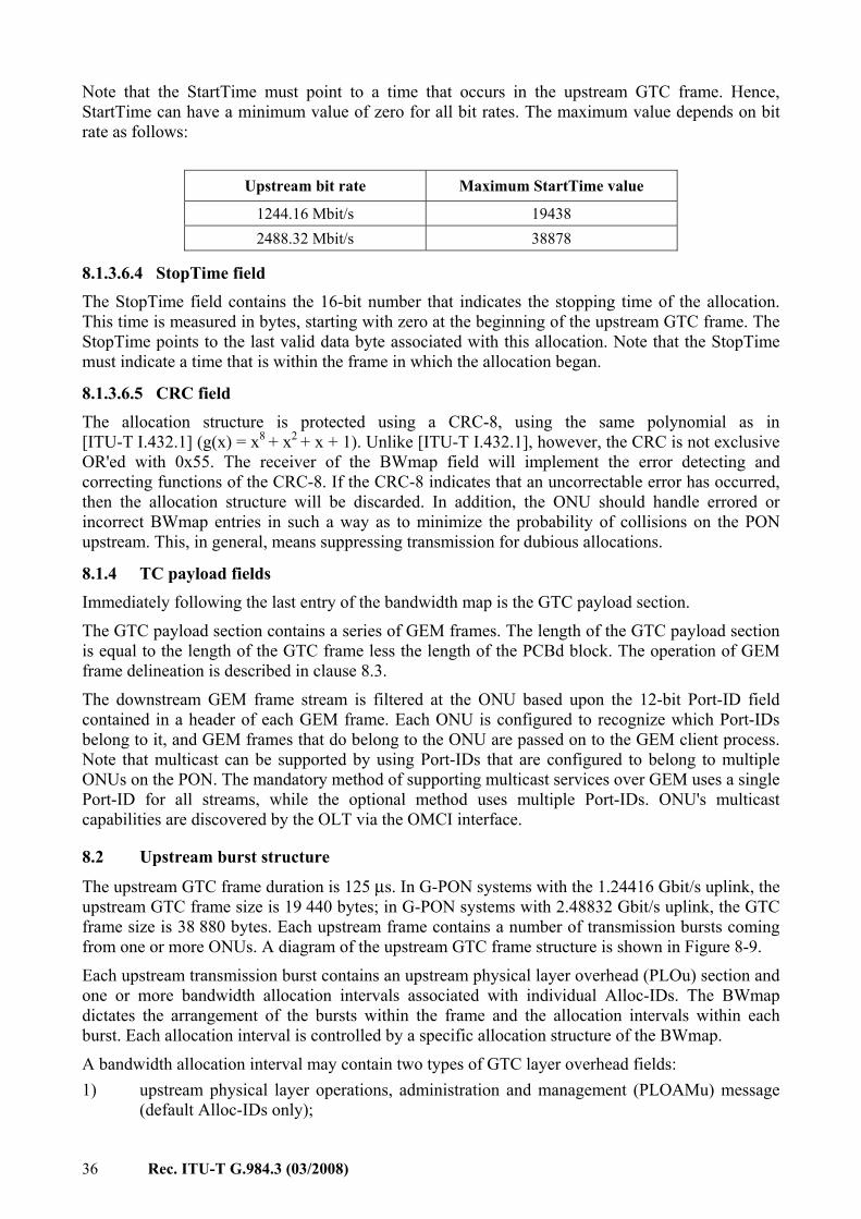
36 Rec. ITU-T G.984.3 (03/2008)
Note that the StartTime must point to a time that occurs in the upstream GTC frame. Hence, StartTime can have a minimum value of zero for all bit rates. The maximum value depends on bit rate as follows:
Upstream bit rate Maximum StartTime value
1244.16 Mbit/s 19438 2488.32 Mbit/s 38878
8.1.3.6.4 StopTime field The StopTime field contains the 16-bit number that indicates the stopping time of the allocation. This time is measured in bytes, starting with zero at the beginning of the upstream GTC frame. The StopTime points to the last valid data byte associated with this allocation. Note that the StopTime must indicate a time that is within the frame in which the allocation began.
8.1.3.6.5 CRC field The allocation structure is protected using a CRC-8, using the same polynomial as in [ITU-T I.432.1] (g(x) = x8 + x2 + x + 1). Unlike [ITU-T I.432.1], however, the CRC is not exclusive OR'ed with 0x55. The receiver of the BWmap field will implement the error detecting and correcting functions of the CRC-8. If the CRC-8 indicates that an uncorrectable error has occurred, then the allocation structure will be discarded. In addition, the ONU should handle errored or incorrect BWmap entries in such a way as to minimize the probability of collisions on the PON upstream. This, in general, means suppressing transmission for dubious allocations.
8.1.4 TC payload fields Immediately following the last entry of the bandwidth map is the GTC payload section.
The GTC payload section contains a series of GEM frames. The length of the GTC payload section is equal to the length of the GTC frame less the length of the PCBd block. The operation of GEM frame delineation is described in clause 8.3.
The downstream GEM frame stream is filtered at the ONU based upon the 12-bit Port-ID field contained in a header of each GEM frame. Each ONU is configured to recognize which Port-IDs belong to it, and GEM frames that do belong to the ONU are passed on to the GEM client process. Note that multicast can be supported by using Port-IDs that are configured to belong to multiple ONUs on the PON. The mandatory method of supporting multicast services over GEM uses a single Port-ID for all streams, while the optional method uses multiple Port-IDs. ONU's multicast capabilities are discovered by the OLT via the OMCI interface.
8.2 Upstream burst structure
The upstream GTC frame duration is 125 μs. In G-PON systems with the 1.24416 Gbit/s uplink, the upstream GTC frame size is 19 440 bytes; in G-PON systems with 2.48832 Gbit/s uplink, the GTC frame size is 38 880 bytes. Each upstream frame contains a number of transmission bursts coming from one or more ONUs. A diagram of the upstream GTC frame structure is shown in Figure 8-9.
Each upstream transmission burst contains an upstream physical layer overhead (PLOu) section and one or more bandwidth allocation intervals associated with individual Alloc-IDs. The BWmap dictates the arrangement of the bursts within the frame and the allocation intervals within each burst. Each allocation interval is controlled by a specific allocation structure of the BWmap.
A bandwidth allocation interval may contain two types of GTC layer overhead fields: 1) upstream physical layer operations, administration and management (PLOAMu) message
(default Alloc-IDs only);

Rec. ITU-T G.984.3 (03/2008) 37
2) upstream dynamic bandwidth report (DBRu).
The OLT uses the Flags field of the allocation structure to indicate whether or not the PLOAMu and/or DBRu fields shall be included into the corresponding upstream allocation interval. The OLT should request PLOAMu transmission only in allocation intervals associated with the Default Alloc-ID of any given ONU.
Figure 8-8 shows the detail of the physical and GTC layer overheads associated with an upstream transmission burst. Each burst begins with the upstream physical layer overhead (PLOu) section which is composed of preamble, delimiter and the 3-byte burst header.
The PLOu and burst mode overhead are distinct but partially overlapping concepts. Unlike PLOu, which refers to the fields actually transmitted by the ONU, the burst mode overhead refers to the time intervals that are required to provide proper burst isolation and delineation. The burst mode overhead is composed of guard time, preamble time and delimiter time, all of which remain invariant for all the ONUs on the PON for as long as the PON is operational.
While providing bandwidth allocations to specific Alloc-IDs, the OLT has to take into account the bandwidth and latency demands of the corresponding PLOAMu and DBRu channels. When generating a BWmap combining the individual allocation structures, the OLT has to provide sufficient allowances for the burst mode overhead times and the burst headers,
The requirement to prepend the PLOu section to a sequence of allocation intervals is implicit in the arrangements of the allocations themselves. The rule is that the PLOu must be sent at the start of each burst; in other words, every time an ONU takes over the PON medium from another ONU, it must send a new copy of the PLOu section. The contiguous allocations (the StopTime of the preceding allocation structure is exactly 1 byte less than the StartTime of the next allocation structure) are considered to belong to the same burst and do not require the PLOu section in-between. Note that the requirement for contiguous allocations forbids the OLT from leaving gaps between the same-ONU allocations. Such allocations must either be exactly contiguous or they must be scheduled as if they belong to two bursts from different ONUs. If, while parsing the BWmap, an ONU, for any reason, does not recognize a contiguous allocation structure as one of its own, the ONU would have to turn the laser off and, in case the lost allocation is shorter than the required PLOu plus guard time, may also lose one or more subsequent contiguous allocations as a result.
In any allocation interval, following the required GTC overhead fields, the user payload data is sent until the location indicated by the StopTime pointer. The StopTime pointer must always be larger than the associated StartTime pointer, in that the smallest usable allocation is 2 bytes, which would be for a DBRu-only transmission. In addition, contiguous pointers are not allowed to bridge over two BWmaps. In other words, every upstream GTC frame must begin with an independent (non-contiguous) transmission.

38 Rec. ITU-T G.984.3 (03/2008)
Figure 8-8 – Details of physical and GTC layer upstream overhead
8.2.1 Scrambling of the upstream burst The upstream burst is scrambled using a burst-synchronous scrambling polynomial. The polynomial used is x7 + x6 + 1. This pattern is added modulo two to the upstream data. The shift register used to calculate this polynomial is reset to all-ones at the first bit following the delimiter field of the PLOu of the first upstream allocation, and is allowed to run until the last bit of the transmission. If the ONU transmits several contiguous allocations, the upstream scrambler should not be reset at any of the internal boundaries.
8.2.2 Physical layer overhead upstream (PLOu) The PLOu data includes preamble, delimiter and the burst header containing three fields of data that correspond to the ONU as a whole. The PLOu section is sent at the beginning of any transmission burst of an ONU. Note that, to maintain connectivity with the ONU, the OLT should attempt to allocate an upstream transmission to every ONU at some minimum interval. The duration of this interval is determined by the service parameters of that ONU.
The GTC layer sources the PLOu. The preamble and delimiter are formed as dictated by the OLT in the Upstream_Overhead and Extended_Burst_Length messages Note that the PLOu bytes are transmitted immediately prior to the byte indicated by the StartTime pointer.
8.2.2.1 BIP field The BIP field is an 8-bit field that contains the bit interleaved parity (exclusive OR) of all bytes transmitted since the last BIP (not including the last BIP) from this ONU, excluding the preamble and delimiter bytes, and FEC parity bytes (if present). The OLT receiver shall compute the bit interleaved parity for each ONU burst excluding the FEC parity bytes (if present) and after FEC correction has been applied (if supported), and compare its result to the received BIP field in order to measure the number of errors on the link.
8.2.2.2 ONU-ID field The ONU-ID field is an 8-bit field that contains the unique ONU-ID of the ONU that is sending this transmission. The ONU-ID is assigned to the ONU during the ranging process. Before the ONU-ID is assigned, the ONU shall put the unassigned ONU-ID (255) in this field. The OLT can check this field against its allocation records to confirm that the correct ONU is transmitting.
8.2.2.3 Ind field The indication field provides real time ONU status reports to the OLT. The format of the Ind field is given below.

Rec. ITU-T G.984.3 (03/2008) 39
Bit position Function
7 (MSB) Urgent PLOAMu waiting (1 = PLOAM waiting, 0 = no PLOAMs waiting) 6 FEC status (1 = FEC on, 0 = FEC off) 5 RDI status (1 = Defect, 0 = OK) 4 Reserved (Note) 3 Reserved (Note) 2 Reserved (Note) 1 Reserved (Note)
0 (LSB) Reserved for future use NOTE – Bits 1 through 4 shall be ignored by the OLT. They shall not be reassigned by vendors or standards organizations.
Note that when the ONU has indicated that an urgent PLOAM is waiting, the OLT should issue an upstream allocation that permits the ONU to send this PLOAM message in a timely manner. The response time should be less than 5 ms during normal operation.
Also note that the ONU will assert the PLOAMu waiting bit for as long as it has one or more PLOAM messages pending transmission upstream. The OLT scheduling algorithm should take this fact into account when determining when to send PLOAMu allocations.
8.2.3 PLOAM upstream (PLOAMu) The PLOAMu field is 13 bytes in length, and contains the PLOAM message as defined in clause 9. This field is sent when indicated by the Flags field in the allocation structure.
8.2.4 Power levelling sequence upstream (PLSu) The power levelling sequence feature is deprecated. The PLSu Flag bit in the allocation structures should be set to zero. The ONU should ignore the PLSu Flag bit, but may, at its own discretion, append an additional transmission of up to 500 ns (78 bytes) to a Serial_Number_ONU message sent upstream while in either the serial number or ranging states (see clause 10.2.5.2).
8.2.5 Dynamic bandwidth report upstream (DBRu)
The DBRu structure contains information that is tied to a T-CONT entity, as opposed to the ONU as a whole. This field is sent when the corresponding flags are set in the appropriate allocation structure within the BWmap.
8.2.5.1 DBA field The DBA field contains the traffic status of the T-CONT in question. An 8-, 16- or 32-bit field is reserved for this purpose, depending on the DBA report format mode requested by the appropriate allocation structure. The coding of this field is described in clause 8.4. Note that the ONU must transmit the appropriate length DBA field, even if that DBA format mode is deprecated by the standard or not supported by the equipment, to maintain delineation.
8.2.5.2 CRC field The DBRu structure is protected using a CRC-8, using the same polynomial as in [ITU-T I.432.1] (g(x) = x8 + x2 + x + 1). Unlike [ITU-T I.432.1], however, the CRC is not exclusive OR'ed with 0x55. The receiver of the DBRu field will implement the error detecting and correcting functions of the CRC-8. If the CRC-8 indicates that an uncorrectable error has occurred, then the information in the DBRu will be discarded.

40 Rec. ITU-T G.984.3 (03/2008)
8.2.6 Upstream GTC payload section Besides the GTC overhead, each upstream allocation interval contains the GTC payload section, which is used to carry GEM-delineated frames (Figure 8-9). The length of this payload is given by the duration of the allocation less the size of the requested overheads. The OLT must maintain multiple instances of the GEM delineation state machine, and buffer-fragmented user data frames until completed. The operation of frame delineation in GEM is described in clause 8.3.
Figure 8-9 – Upstream GTC burst
8.3 Mapping of GEM frames into GTC payload GEM traffic is carried over the GTC protocol in transparent fashion. The GEM protocol has two functions: to provide delineation of the user data frames and to provide the port identification for multiplexing. Note that the term 'user data frames' denotes frames either going to or coming from a user.
Figure 8-10 – Mapping of GEM frames into GTC payload
8.3.1 GEM header format The format of the GEM header is shown in Figure 8-11. The GEM header contains the payload length indicator (PLI), Port-ID, payload type indicator (PTI) and a 13-bit header error control (HEC) field.
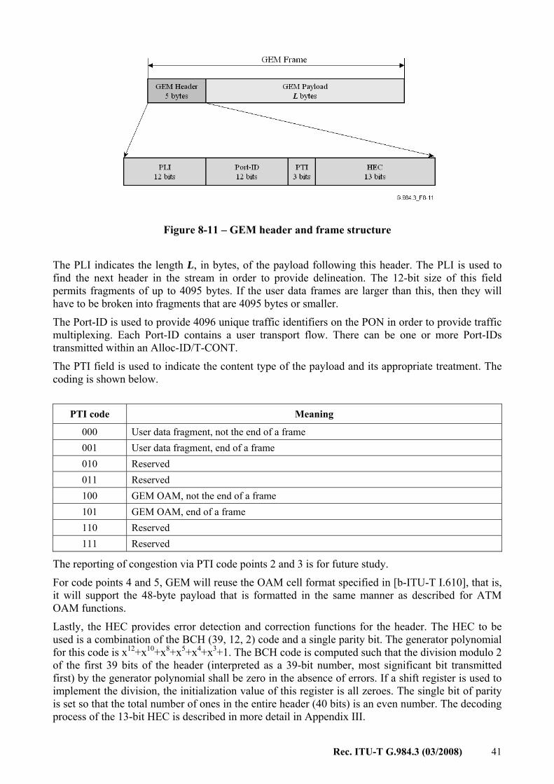
Rec. ITU-T G.984.3 (03/2008) 41
Figure 8-11 – GEM header and frame structure
The PLI indicates the length L, in bytes, of the payload following this header. The PLI is used to find the next header in the stream in order to provide delineation. The 12-bit size of this field permits fragments of up to 4095 bytes. If the user data frames are larger than this, then they will have to be broken into fragments that are 4095 bytes or smaller.
The Port-ID is used to provide 4096 unique traffic identifiers on the PON in order to provide traffic multiplexing. Each Port-ID contains a user transport flow. There can be one or more Port-IDs transmitted within an Alloc-ID/T-CONT.
The PTI field is used to indicate the content type of the payload and its appropriate treatment. The coding is shown below.
PTI code Meaning
000 User data fragment, not the end of a frame 001 User data fragment, end of a frame 010 Reserved 011 Reserved 100 GEM OAM, not the end of a frame 101 GEM OAM, end of a frame 110 Reserved 111 Reserved
The reporting of congestion via PTI code points 2 and 3 is for future study.
For code points 4 and 5, GEM will reuse the OAM cell format specified in [b-ITU-T I.610], that is, it will support the 48-byte payload that is formatted in the same manner as described for ATM OAM functions.
Lastly, the HEC provides error detection and correction functions for the header. The HEC to be used is a combination of the BCH (39, 12, 2) code and a single parity bit. The generator polynomial for this code is x12+x10+x8+x5+x4+x3+1. The BCH code is computed such that the division modulo 2 of the first 39 bits of the header (interpreted as a 39-bit number, most significant bit transmitted first) by the generator polynomial shall be zero in the absence of errors. If a shift register is used to implement the division, the initialization value of this register is all zeroes. The single bit of parity is set so that the total number of ones in the entire header (40 bits) is an even number. The decoding process of the 13-bit HEC is described in more detail in Appendix III.

42 Rec. ITU-T G.984.3 (03/2008)
Once the header has been assembled, the transmitter computes the exclusive OR of the header with the fixed pattern: 0x0xB6AB31E055, and transmits the result. The receiver computes the exclusive OR of the received bits with the same fixed pattern to recover the header. This is done to insure that a series of idle frames will have sufficient content to permit correct delineation.
8.3.2 GEM frame delineation and synchronization The delineation process in G-PON requires the presence of a GEM header at the beginning of every downstream and upstream GTC payload section. The receiver is thereby assured of finding the first header and can find subsequent headers by using the PLI as a pointer. In other words, the receiver immediately transitions to the 'Sync' state at the beginning of every GTC payload section. However, in the case of uncorrectable errors in the header, the delineation process may lose synchronization with the data stream. The receiver will then attempt to reacquire synchronization by implementing the state machine shown in Figure 8-12. In the Hunt state, the receiver searches for a GEM header HEC byte-by-byte (as the byte alignment is already provided by the GTC framing). When it finds one, it transitions to the Pre-sync state, where it looks for the HEC at the location indicated in the previously found header. If that HEC matches, then the transition is made to the Sync state. If it does not, then the transition is made to the Hunt state. Note that implementations can choose to have multiple instances of the Pre-sync state, so that false HEC matches do not block the correct delimiter from being detected. Also, the receiving process can buffer the data received while in the Pre-sync state and, if the transition to Sync state is successful, the buffered data can be correctly presumed to be a valid user data fragment.
Figure 8-12 – GEM delineation state machine
To provide for rate decoupling, an idle GEM frame is defined. If there are no user frames to be sent, the transmit process will generate these idle frames to fill the empty time. The receiver will use these frames to maintain synchronization and, of course, they have no data to pass up to the GEM client. The idle GEM frame header is defined to be all-zeroes. This implies that the actual transmitted pattern is 0xB6AB31E055, due to the XOR operation before transmission.
8.3.3 User frame fragmentation Because user data frames are of random length, the GEM protocol must support fragmentation of user data frames to permit the insertion of the GEM header at the beginning of each GTC payload section. Note that fragmentation can occur in both the downstream and the upstream directions. The least significant bit of the PTI field in the GEM header is used for this purpose. Each user data frame can be divided into a number of fragments. Each fragment is prepended with a header, and the PTI field indicates which fragment contains the end of the user data frame. A few cases of PTI usage are illustrated in Figure 8-13.

Rec. ITU-T G.984.3 (03/2008) 43
Figure 8-13 – Fragment field use cases
It is important to note that each user data fragment produced is transmitted contiguously. That is, a user data fragment cannot straddle a GTC frame boundary. This is a natural consequence of the requirement that a GEM header must begin every GTC payload section. Therefore, the fragmentation process must be aware of the amount of time remaining in the current GTC payload section, and must fragment its user data frames appropriately. Another implication of this fact is the transmission of idle GEM frames. In some cases, the completion of a prior user frame may leave 4 or fewer bytes left in the GTC payload. This is less than the minimum GEM frame size. In the case where X bytes of time remaining in the GTC payload (0 < X < 5), the transmitting process shall send a pre-empted GEM header pattern, defined to be the first X bytes of the idle GEM header pattern. The receiving process will recognize that the header is pre-empted, and disregard it. In any case, GEM delineation will be restored at the beginning of the next GTC payload.
The fragmentation process inherent in GEM can be used for two purposes in the GTC system. The first has already been mentioned, that is to insert a GEM header at the beginning of each GTC payload. Additionally, if time-sensitive data, such as voice traffic, must pre-empt the transmission of non-time-sensitive traffic, fragmentation provides a way for this to happen. In general, these two uses of fragmentation could be implemented by two separate processing steps, the first to insert the urgent traffic, and the second to insert headers to fit the GTC payload. However, a simpler method is to leverage a single stage of fragmentation to do both functions. In this situation, the urgent user data frames are always sent at the beginning of each GTC payload. Because the GTC frame has a periodicity of 125 μs, this should provide sufficiently low latency for the urgent data. This arrangement is illustrated in Figure 8-14.

44 Rec. ITU-T G.984.3 (03/2008)
Figure 8-14 – Fragmentation and pre-emption
Each ONU is required to have at least two GEM re-assembly buffers to support the usage of time-urgent fragmentation. Support for more re-assembly buffers is possible. The OLT should not interleave more than two user data frames to any single ONU unless it determines that the ONU has additional capability. The OLT is required to have at least two GEM re-assembly buffers per Alloc-ID for the same purpose. Support for more re-assembly buffers is possible. The ONU should not interleave more than two user data frames unless it determines that the OLT has additional capability.
8.3.4 Mapping of user services into GEM frames The mapping of user services into GEM is described in Appendix I.
8.4 Status reporting DBA signalling and configuration This Recommendation specifies piggyback status reporting using the DBRu structure of the upstream burst as the only SR DBA signalling mechanism, and allows two status report formats: Mode 0 and Mode 1. The backward-compatibility issues arising from the fact that the earlier release of this Recommendation also specified the status indication and whole ONU reporting mechanisms and the third format mode for the piggyback reporting mechanism, known as Mode 2, are discussed in clause 8.4.5.
Report format Mode 0 is the default supported method. The discussion of Mode 1 DBRu reporting is provided in clause 8.4.6.
Upon ONU activation, the OLT and ONU must perform a handshaking procedure to negotiate the type of DBA reports that will be used. The G-PON OMCI channel is used for this purpose. Until the OMCI handshake is completed, the DBA features should not be used. However, the transport system is made to be fault-tolerant by setting requirements for the ONU to always produce the correct format of report requested by the OLT, regardless of its DBA capabilities. The specifics of the options, their management and fault conditions are outlined below.
8.4.1 Definition of the DBRu report The piggyback DBA report consists of a 1-byte or 2-byte DBRu message that is prepended to the ONU's upstream transmission. The OLT requests the transmission of the DBRu by setting the appropriate code point in the Flags field of a specific allocation structure within the BWmap. The DBRu message indicates the amount of data that is present in the logical buffer corresponding to the Alloc-ID of that allocation structure.
The allocation structure containing the DBRu request may also contain the regular allocation to the given Alloc-ID. Recognizing the ambiguity that existed, but was not addressed, in the original version of this Recommendation, this version leaves it to the ONU's discretion to report the logical

Rec. ITU-T G.984.3 (03/2008) 45
buffer occupancy either before or after the present allocation has been served. The following requirements apply: 1) The ONU shall consistently follow the selected semantics of the DBRu reports. 2) The OLT DBA algorithm shall be robust to either DBRu report semantics. 3) The DBRu report shall not take into account any subsequent allocations that may be
communicated to the ONU after the allocation in which the DBRu report is requested but before the DBRu report is transmitted.
Note that the third requirement maintains consistency of DBRu reports across different ONUs on the PON, eliminating the dependence of the reported value upon the fibre distance.
The report is protected by the CRC-8 octet that is a part of the DBRu structure. The format of the Flags field is specified in clause 8.1.3.6.2 and the format of the DBRu structure is defined in clause 8.2.5.
8.4.2 Buffer occupancy representation The ONU tracks the occupancy of the logical buffer associated with a particular Alloc-ID in terms of reporting blocks. The size of reporting block should be the same for all Alloc-IDs on the same PON interface. The size of reporting block is communicated via the OMCI channel upon ONU activation and has a default value of 48 bytes.
The buffer occupancy measure, expressed in reporting blocks, is obtained by rounding up the corresponding value in bytes. If k packets of a certain type with lengths Li bytes (i = 1,…,k) are stored in the logical buffer associated with an Alloc-ID, the buffer occupancy for that type, R, is calculated as follows.
⎟⎟⎠
⎞⎜⎜⎝
⎛= ∑
=
k
iiL
BceilR
1
1
where B is the reporting block size, and ceil(X) is the function that returns the smallest integer that is greater than or equal to the argument X.
For upstream transmission within the DBRu report, the buffer occupancy value is encoded into a fixed-size single octet field. This non-linear encoding is specified by the following table:
Table 8-1 – Code points in the DBA reporting fields
Queue length Binary input (ONU) Coding of octet Binary output (OLT) 0-127 00000000abcdefg 0abcdefg 00000000abcdefg
128-255 00000001abcdefx 10abcdef 00000001abcdef1
256-511 0000001abcdexxx 110abcde 0000001abcde111
512-1023 000001abcdxxxxx 1110abcd 000001abcd11111
1024-2047 00001abcxxxxxxx 11110abc 00001abc1111111
2048-4095 0001abxxxxxxxxx 111110ab 0001ab111111111
4096-8191 001axxxxxxxxxxx 1111110a 001a11111111111
>8191 01xxxxxxxxxxxxx 11111110 011111111111111
Invalid N/A 11111111 N/A
8.4.3 DBRu format modes
This Recommendation allows two piggyback DBRu format modes: • Mode 0: A single one-octet field containing the non-linear coding of the total amount of
data in the logical buffer associated with an Alloc-ID.

46 Rec. ITU-T G.984.3 (03/2008)
• Mode 1: Two one-octet fields, the first containing the non-linear coding of the amount of data marked as "yellow" on admission to the buffer, and the second containing the non-linear coding of the amount of data marked as "green" on admission to the buffer.
While Mode 0 reporting is applicable to Alloc-IDs without limitations, Mode 1 reporting is applicable to the Alloc-IDs that are eligible for non-assured or best-effort bandwidth sharing and whose constituent traffic flows are subject to traffic regulation (by means of an ingress policer that may optionally be preceded by a shaper) at the ONU. The ONU per-flow traffic regulator shall be equivalent to a dual token bucket, implementing the committed information rate (CIR) and excess information rate (EIR) tests on each arriving data packet. The traffic regulator shall admit a packet to the buffer as "green" if it passes the CIR test, and as "yellow" if it fails the CIR test but passes the EIR test. The traffic regulator shall discard the packets that fail both CIR and EIR tests and are marked as "red".1
8.4.4 Options available to the ONU and OLT The support for piggyback DBA reporting is optional for the ONU. If the ONU does support piggyback reporting, it must support format Mode 0, and may optionally support format Mode 1. The OLT must support the piggyback DBRu format Mode 0, and may optionally support format Mode 1. The specific use of the DBRu reports is left to the OLT implementation.
8.4.5 Backward compatibility and handling of exceptional cases The earlier version of this Recommendation specified status indication and whole ONU reporting in addition to the piggyback reporting mechanism, and within the latter Mode 2 format in addition to format Modes 0 and 1. Conceivably, a G-PON network element (OLT or ONU) compliant with this version of this Recommendation may have to interoperate in the field with another G-PON device built to the earlier specifications. The following list contains the principles that should be followed in order to ensure backward-compatibility. 1) Status indication DBA has been deprecated. The ONU shall place zeros in bits 1 through 4
of the upstream burst Ind field (status indication report). The OLT shall ignore these bits. These bits shall not be allocated to any other function by standards bodies or vendors.
2) Whole ONU reporting DBA has been deprecated. The OLT shall not attempt to assign to an ONU an Alloc-ID with the Alloc-ID type equal to 2 (DBA payload). Alloc-ID type 2 shall not be allocated to any other use by standards organizations or vendors. If an ONU receives an Assign_Alloc-ID message with Alloc-ID type 2, it should withhold the acknowledgment and ignore any subsequent allocations to that Alloc-ID as if the Alloc-ID did not belong to that ONU.
3) The Mode 2 piggyback report format has been deprecated. The ONU shall not advertise the Mode 2 piggyback reporting capabilities (see [b-ITU-T G.984.4] ANI-G ME). The OLT shall not request Mode 2 status reports, that is, bits 7 and 8 of the Flags field of any BWmap allocation structure should not be set to 1 at the same time. If the ONT receives a DBRu request for a format Mode 2 status report, it shall respond with a 5-byte message containing 4 invalid codes and the correct CRC.
4) The OLT must issue DBRu requests for the format modes within the ONU's capabilities that the OLT discovers via the OMCI. Should the ONU receive a DBRu request for an unsupported format mode, it shall respond with a DBRu message that has a correct size for the requested format mode but contains the invalid occupancy codes with the correct CRC.
____________________ 1 Note that the semantics of the traffic regulator specified here matches the two-rate three-colour marker of
[b-RFC 4115] as well as the bandwidth profile algorithm of [b-MEF 10.1], but is different from the two-rate three-colour marker of [b-RFC 2698].

Rec. ITU-T G.984.3 (03/2008) 47
The specified ONU actions in the latter two cases allow the OLT to maintain delineation of the burst since the length of the DBRu sent by the ONU always matches that expected by the OLT.
8.4.6 Implementation note on Mode 1 DBRu reporting While the present Recommendation supports both Mode 0 and Mode 1 piggyback DBRu report formats, the DBA bandwidth assignment models discussed in clauses 7.4.4 and 7.4.5 are based on the dynamic information that can be communicated to the OLT using Mode 0 reports only. Specifically, the model employs the concept of offered traffic load RL(t) = [B(t) + A(t,t+∆)]/∆, but is not concerned with the colour components of the offered load, that can be defined as follows:
Δ
Δ++=
),()()(
ttAtBtR grgr
Lgr (8-1)
and
Δ
Δ++=
),()()(
ttAtBtR yeye
Lye (8-2)
Here subscripts "gr" and "ye" refer to green and yellow components; B(t) is the amount of respectively coloured traffic in the buffer at time t, and the optional term A(t, t+∆) denotes the new arrivals of the respectively coloured traffic within the time interval (t, t+∆) of fixed duration ∆.
Figure 8-15 – Ideal and realistic colour partition of the traffic in the buffer
Assume the traffic regulator is specified with the four parameters: committed information rate (CIR), committed burst size (CBS), excess information rate (EIR), excess burst size (EBS), allow for convenience peak information rate PIR = CIR + EIR, and consider a single traffic flow feeding the buffer. In the hypothetical situation of an ideally smooth traffic arrival process, the green component of the offered load can be found exactly as:
{ }CIRtRtR LLgr );(min)( = (8-3)

48 Rec. ITU-T G.984.3 (03/2008)
In Figure 8-15, which shows the colour partition of the regulated traffic versus the total post-regulator offered load (in other words, versus the rate at which the traffic is actually admitted to the buffer), this situation corresponds to the ideal case (a). In reality, however, the traffic is bursty, and the burstiness of the arrival process distorts the colour partition of traffic in the buffer. Given the parameters of the regulator, the green component of the offered load can be bounded as follows:
{ }CIRtRtREBSCBS
CBSEIRCIR
CIRtR LLgrL );(min)(;min)( ≤≤⎭⎬⎫
⎩⎨⎧
++ (8-4)
Double inequality (equation 8-4) defines an area on the colour partition diagram where the traffic may appear green or yellow depending on the characteristics of the arrival process. This is shown in Figure 8-15b for the case when the parameters of the regulator are balanced, producing the tightest possible uncertainty area. Within that area, the OLT DBA algorithm employing Mode 1 reporting has no a priori knowledge of the actual traffic distribution.
Note that once traffic passes the ingress regulator, it is commonly required that the traffic management mechanisms depend on the longer-term averages rather than on shorter-term fluctuations. For example, per [b-RFC 2597], "The dropping algorithm MUST be insensitive to the short-term traffic characteristics of the microflows using an AF class. That is, flows with different short-term burst shapes but identical longer-term packet rates should have packets discarded with essentially equal probability".
Whether and how the information provided by the Mode 1 report format can be used by the OLT DBA algorithm is left to the implementation.
9 GTC messages There are three methods to convey OAM information between the network management station and the OLT on the one hand and the ONUs on the other hand: • Embedded OAM channel. Several fields are defined in the downstream and upstream
frame structures. These fields convey real-time information such as security exchange, DBA and link BER monitoring. The embedded OAM channel information is provided in Clause 8.
• Physical layer OAM (PLOAM) messaging channel. A dedicated 13-byte message can be sent downstream by the OLT to the ONUs and by the ONUs upstream to the OLT conveying OAM functions between them.
• ONU management and control interface (OMCI). OMCI messages are transported over a dedicated GEM channel. The OMCI transport mechanism is described in clause 14. The syntax of the OMCI is specified in [b-ITU-T G.984.4].
This clause focuses on the PLOAM messages.
9.1 PLOAM message format The physical layer OAM (PLOAM) channel supports the PON TC layer management functions, including ONU activation, OMCC establishment, encryption configuration, key management and alarm signalling. It is transported in the 13-byte PLOAM message field within the overhead section of the downstream GTC frame and default Alloc-ID allocation of the upstream GTC burst.
The PLOAM message structure is shown in Figure 9-1, and is further defined in the following subclauses.

Rec. ITU-T G.984.3 (03/2008) 49
OctetsONU ID 1 Message ID 1
Data 10
CRC 1
Octets withinframe transmittedtop-to-bottom
MSB LSB B7 B0 Bits within frame transmitted left-to-right
Figure 9-1 – Generic message structure
9.1.1 ONU-ID The ONU-ID addresses a particular ONU. During the ranging protocol, the ONU is assigned a number, ONU-ID. This ONU-ID can be from 0 to 253. For broadcast to all ONUs, this field is set to 0xFF.
9.1.2 Message-ID Indicates the type of the message.
9.1.3 Message data These octets are used for the payload of the GTC messages.
9.1.4 CRC This field is the frame check sequence. The message will be discarded at reception when the CRC is incorrect.
The CRC field shall contain the coefficients of the polynomial obtained as the remainder of the division (modulo 2) of the polynomial representation of the message with all-zero CRC octet by the generator polynomial x8 + x2 + x + 1.
At the transmitter, the initial content of the register of the device computing the remainder of the division is preset to all-zeroes and is then modified by division of the message with the CRC octet filled with eight zeros by the generator polynomial (as described above); the resulting remainder is transmitted as the 8-bit CRC.
9.2 Control messages
The processing time of all downstream messages is within 750 μs, which is the time required by the ONU to process the downstream message and prepare any corresponding upstream actions.
9.2.1 Downstream message definition The following table shows the downstream message definition.

50 Rec. ITU-T G.984.3 (03/2008)
Message name Function Trigger Times sent Effect of receipt
1 Upstream_Overhead To instruct the ONU which pre-assigned delay and the number of preamble bytes to use in the upstream direction. In addition, ONU optical power is defined.
Each time activation process is started.
3 The ONU sets the pre-assigned delay.
2 Assign_ONU-ID To link a free ONU-ID number with the serial number also provided in this message.
When the OLT has found the serial number of a unique ONU.
3 The ONU with this serial number sets its ONU-ID and also its default Alloc-ID.
3 Ranging_Time To indicate the value (expressed in number of upstream bits) that the specified ONU must fill into its equalization delay register. Dedicated field indicates if this EqD is for the main or protection path.
When the OLT decides that the delay must be updated, see ranging protocol.
3 The ONU fills in the equalization delay register with this value.
4 Deactivate_ONU-ID To instruct an ONU with this ONU-ID to stop sending upstream traffic and reset itself. It can also be a broadcast message.
When LOS, LOF, LCD, LOA and SUF alarms are detected from the ONU.
3 The ONU with this ONU-ID switches off the laser; the ONU-ID, OMCI Port-ID and all Alloc-ID assignments are discarded. ONU moves to the Standby state.
5 Disable_Serial_Number To disable/enable an ONU with this serial number.
On command from the OpS.
3 Disable option: Moves the ONU to the Emergency Stop state. The ONU cannot respond to upstream bandwidth allocations. Enable option: Moves the ONU to the Standby state. The ONU restarts the activation process, as specified in clause 10.
6 Encrypted_Port-ID To indicate to ONUs which channels are encrypted or not.
When a new channel must be encrypted or not.
3 Mark/unmark this channel as encrypted. Send 1 acknowledge after each correctly received message.

Rec. ITU-T G.984.3 (03/2008) 51
Message name Function Trigger Times sent Effect of receipt
7 Request_Password To request the password from an ONU in order to verify it. The OLT has a local table of passwords of the connected ONUs.
After an ONU is ranged. This is optional for OLT to use; mandatory for ONU to respond
1 Send the password message 3 times.
8 Assign_Alloc-ID To instruct an ONU that the specified allocation ID is assigned to it.
When OLT discovers that multiple T-CONTs are supported by the ONU.
3 Send 1 acknowledge after each correctly received message. The ONU shall respond to the bandwidth allocations with the specified Alloc-ID. Until a T-CONT is properly mapped to the Alloc-ID, the idle GEM frames shall be sent.
9 No message No message available when a PLOAM field is transmitted.
Empty message queue.
–
10 POPUP The OLT forces all the ONUs which are in POPUP state and not in LOS/LOF state to go from POPUP state to Ranging state (O4) or commanding the specific ONU to go directly to Operation state (O5).
To speed up the activation of ONUs in a LOS state.
3 The ONU moves to Ranging state (O4), or to Operation state (O5).
11 Request_Key The OLT triggers the ONU to generate a new encryption key and send it upstream.
At a frequency determined by the OpS.
1 Send the encryption key message three times.
12 Configure Port-ID This message links the internally processed OMCI channel at the ONU with a 12-bit Port-ID. The Port-ID is appended to the GEM overhead and used as an addressing mechanism to route OMCI over the GEM channel.
On command from the OpS.
3 Logical management port is assigned with the Port-ID. Send 1 acknowledge after each correctly received message.

52 Rec. ITU-T G.984.3 (03/2008)
Message name Function Trigger Times sent Effect of receipt
13 Physical_Equipment_ Error (PEE)
To indicate to the ONUs that the OLT is unable to send both GEM frames and OMCC frames.
When the OLT detects it cannot send both GEM frames and OMCC frames.
1 time/ second
PEE alarm is asserted at the ONU.
14 Change_Power_Level The OLT triggers the ONU to either increase or decrease its transmitted power level.
When the OLT detects that the ONU power is less/more than a predefined threshold.
1 ONU adjusts its transmitted power level accordingly.
15 PST message To check the ONU-OLT connectivity in a survivable PON configuration, and to perform APS.
Periodically, and also after faults are detected.
1 time/ second
ONU checks link number, and acts upon APS commands.
16 BER Interval It defines the accumulation interval per ONU expressed in the number of downstream frames for the ONU counting the number of downstream bit errors.
OpS defines this interval and can focus on one particular ONU.
3 The ONU starts a timer, and accumulates the downstream errors. An acknowledge is sent for each correct message.
17 Key_Switching_Time The OLT indicates to the ONU when to begin using the new encryption key.
When the OLT is ready to change the key.
3 ONU prepares to switch the key at the indicated time. Send 1 acknowledge after each correctly received message.
18 Extended_Burst_Length To instruct the ONU the number of type 3 preamble bytes to use in the upstream direction.
Each time activation process is started. Following the upstream overhead message
3 The ONU sets the type 3 preamble length.
9.2.2 Upstream message definition The following table shows the upstream message definition.

Rec. ITU-T G.984.3 (03/2008) 53
Message name Function Trigger Times sent Effect of receipt
1 Serial_Number_ONU It contains the serial number of an ONU.
In Serial_Number state (O3) in response to broadcast serial number request BW allocation; in Ranging state (O4), in response to directed ranging BW allocation.
1 The OLT extracts the serial number and can assign a free ONU-ID to this ONU. Included in the message is the currently used random delay to enable first RTD measurement during SN acquisition.
2 Password To verify an ONU based on its password.
When the OLT requests the password by the "Request_ Password".
3 If OLT receives 3 identical passwords, it is declared as valid. Further processing is system-dependant.
3 Dying_Gasp To inform the OLT that the ONU will power-off in a normal operation. This is to prevent the OLT from issuing unnecessary alarm reports.
The ONU generates this message when the power-off is activated in a normal operation.
At least 3 times
Discard any subsequent alarms for this ONU. Inform OpS.
4 No message Rate decoupling for PLOAM channel, power control opportunity for ONU.
Empty message queue.
None.
5 Encryption key It sends a fragment of the new encryption key to the OLT.
The OLT sends the key request message.
3 for each
fragment
The OLT checks each fragment for errors, and stores the resultant key, if validated. The OLT can then schedule a key switch event.
6 Physical_Equipment_Error (PEE)
To indicate to the OLT that the ONU is unable to send both GEM frames and OMCC frames in the direction from GEM layer to TC layer.
When the ONU detects it cannot send both GEM frames and OMCC frames in the direction from GEM layer to TC layer.
1 time/ second
PEE alarm is asserted at the OLT.
7 PST message To check the ONU-OLT connectivity in a survivable PON configuration, and to perform APS.
Periodically, and also after faults are detected.
1 time/ second
ONU checks link number, and acts upon APS commands.
8 Remote error indication (REI)
Contains the number of BIP detected errors counted during the BER Interval.
When the BER Interval has expired.
1 time/ BER
Interval
The OLT can determine the BER as a function of time for each ONU.

54 Rec. ITU-T G.984.3 (03/2008)
Message name Function Trigger Times sent Effect of receipt
9 Acknowledge This is used by the ONU to indicate the reception of downstream messages.
After receiving correct downstream messages that require acknowledgement.
1 time This message provides for reliable transport of downstream messages.
9.2.3 Downstream message formats The following downstream PLOAM message IDs, representing the deprecated message types, are reserved and should not be reassigned by any standards organization or vendor: – 00000010 – Serial_Number_Mask message. – 00000111 – Configure_VP/VC message.
A PLOAM message with the message ID from this list should not be sent by the OLT and shall be ignored by the ONUs.
9.2.3.1 Upstream_Overhead message
Upstream_Overhead message
Octet Content Description
1 11111111 Broadcast message to all ONUs. 2 00000001 Message identification "Upstream_Overhead". 3 gggggggg gggggggg = Number of guard bits. 4 xxxxxxxx xxxxxxxx = Number of type 1 preamble bits. Type 1 preamble bits
contain the 'all-ones' pattern. This may be set to zero. 5 yyyyyyyy yyyyyyyy = Number of type 2 preamble bits. Type 2 preamble bits
contain the 'all-zeroes' pattern. This may be set to zero. 6 cccccccc cccccccc = Pattern to be used for type 3 preamble bits (Note 1). 7 bbbbbbbb Data to be programmed in delimiter byte 1 (Notes 2 and 3). 8 bbbbbbbb Data to be programmed in delimiter byte 2. 9 bbbbbbbb Data to be programmed in delimiter byte 3.
10 xxemsspp xx = Reserved: e = Status of delay pre-equalization mechanism: "0" = No pre-assigned delay, "1" = Use pre-assigned delay given below. m = Status of SN_Mask mechanism: "0" = SN_Mask disabled, "1" = SN_Mask enabled (Note 5). ss = Max number of extra SN-transmissions sent in response to a single SN-request. For example, ss = 10 means an ONU will send 3 SN-transmissions when responding to a SN-request (Note 6). Default ONU transmit power level mode: pp = "00" – Mode 0: Normal. pp = "01" – Mode 1: Normal – 3 dB. pp = "10" – Mode 2: Normal – 6 dB. pp = "11" – Reserved. (Note 4)

Rec. ITU-T G.984.3 (03/2008) 55
Upstream_Overhead message
Octet Content Description
11 dddddddd MSB of pre-assigned delay (32 byte units). 12 dddddddd LSB of pre-assigned delay (32 byte units).
NOTE 1 – The length of Type 3 preamble can be calculated by subtracting the number of bits allocated to guard time, type 1 preamble and type 2 preamble, by the Upstream_Overhead message, as well as 24 bits of the delimiter from the total burst mode overhead time specified in Table I.2 of [ITU-T G.984.2] The ONU uses the octet 6 pattern to fill the length of type 3 preamble, aligning the MSB of the pattern with the MSB of the preamble, repeating the pattern as many time as necessary, and leaving any partial pattern adjacent to the delimiter. NOTE 2 – The delimiter pattern occupies the last 24 bits of the burst mode overhead time. In those cases when the actual delimiter is shorter than 24 bits, it is the responsibility of the OLT to specify the pattern in octet 7 so that its MSB can serve as the latter part of the preamble. NOTE 3 – For 16-bit delimiters, these values are proposed: 0x85B3, 0x8C5B, 0xB433, 0xB670 and 0xE6D0. For 20-bit delimiter, 0xB5983 is proposed. NOTE 4 – Be mindful that the coding of the power level modes in the upstream overhead message, where 0 is highest and 2 is lowest, is opposite to that in the Serial_Number_ONU message. NOTE 5 – As the Serial_Number_Mask message has been deprecated, the m bit shall be set to 0. NOTE 6 – As multiple SN transmission method has been effectively deprecated, ss bits shall be set to 00.
9.2.3.2 Serial_Number_Mask message The Serial_Number_Mask message has been deprecated.
9.2.3.3 Assign_ONU-ID message
Assign_ONU-ID message
Octet Content Description
1 11111111 Broadcast message to all ONUs. 2 00000011 Message identification "Assign_ONU-ID". 3 pppppppp ONU-ID. 4 abcdefgh Serial number byte 1.
5-10 ..... 11 stuvwxyz Serial number byte 8. 12 Unspecified
NOTE – This message is used to assign an ONU-ID to a physical ONU. Later, Alloc-IDs are assigned to each T-CONT of the specific ONU according to its ONU-ID.
9.2.3.4 Ranging_Time message
Ranging_Time message
Octet Content Description
1 ONU-ID Directed message to one ONU. 2 00000100 Message identification "Ranging_Time". 3 0000000b '0' – Main path EqD.
'1' – Protection path EqD. 4 dddddddd MSB of delay.

56 Rec. ITU-T G.984.3 (03/2008)
Ranging_Time message
Octet Content Description
5 dddddddd 6 dddddddd 7 dddddddd LSB of delay.
8-12 Unspecified
NOTE 1 – The unit of the equalization delay parameter is bits. NOTE 2 – Both the main path EqD and the protection path EqD can be assigned to the ONU using this message.
9.2.3.5 Deactivate_ONU-ID message
Deactivate_ONU-ID message
Octet Content Description
1 ONU-ID or 11111111
Directed message to one ONU or all ONUs. As a broadcast to all ONUs, ONU-ID = 0xFF.
2 00000101 Message identification "Deactivate_ONU-ID" 3-12 Unspecified
9.2.3.6 Disable_Serial_Number message
Disable_Serial_Number message
Octet Content Description
1 11111111 Broadcast message to all ONUs. 2 00000110 Message identification "Disable_Serial_Number". 3 Disable/enable 0xFF: The ONU with this serial number is denied upstream access.
0x0F: All ONUs that were denied upstream access can participate in the ranging process. The content of bytes 4-11 is irrelevant. 0x00: The ONU with this serial number can participate in the ranging process.
4 abcdefgh Serial number byte 1. 5-10 ..... 11 stuvwxyz Serial number byte 8. 12 Unspecified
9.2.3.7 Configure_VP/VC message The Configure_VP/VC message has been deprecated.

Rec. ITU-T G.984.3 (03/2008) 57
9.2.3.8 Encrypted_Port-ID message
Encrypted_Port-ID message
Octet Content Description
1 ONU-ID Directed message to one ONU. 2 00001000 Message identification "Encrypted_Port-ID". 3 xxxxxxba a = 1: Encrypted.
a = 0: Not encrypted. b = 1. If b = 0, message should be ignored by the ONU.
4 abcdefgh abcdefgh = Port-ID[11..4]. 5 ijkl0000 ijkl = Port-ID[3..0]. 6 Unspecified 7 Unspecified
8-12 Unspecified NOTE – This message is not required to complete ranging or to make any connection active. It can be issued at any time in the life of a connection. Changing the encryption mode of an active connection will likely cause temporary service interruption.
9.2.3.9 Request_Password message
Request_Password message
Octet Content Description
1 ONU-ID Directed message to one ONU. 2 00001001 Message identification "Request_Password".
3-12 Unspecified
9.2.3.10 Assign_Alloc-ID message
Assign_Alloc-ID message
Octet Content Description
1 ONU-ID Directed message to one ONU. 2 00001010 Message identification "Assign_Alloc-ID". 3 pppppppp Alloc-ID[11-4]. 4 pppp0000 Alloc-ID[3-0]. 5 Alloc-ID type Indicates for what payload type this Alloc-ID will use:
0,2: Reserved, protected. 1: GEM-encapsulated payload. 3-254: Reserved for future use. 255: De-allocate this Alloc-ID.
6-12 Unspecified

58 Rec. ITU-T G.984.3 (03/2008)
9.2.3.11 No message
No message
Octet Content Description
1 11111111 Broadcast message to all ONUs. 2 00001011 Message identification "no message".
3-12 Unspecified
9.2.3.12 POPUP message
POPUP message
Octet Content Description
1 ONU-ID or 11111111
Directed message to one ONU or all ONUs. As a broadcast to all ONUs, ONU-ID = 0xFF.
2 00001100 Message identification "POPUP". 3-12 Unspecified
NOTE – All ONUs in POPUP state that receive a broadcast POPUP message return to Ranging state. An ONU that receives a specific POPUP message (with its ONU-ID) moves directly to Operation state while keeping its equalization delay, ONU-ID and Alloc-IDs.
9.2.3.13 Request_Key message
Request_Key message
Octet Content Description
1 ONU-ID Directed message to one ONU. 2 00001101 Message identification "Request_Key".
3-12 Unspecified
9.2.3.14 Configure_Port-ID message
Configure Port-ID message
Octet Content Description
1 ONU-ID Directed message to one ONU. 2 00001110 Message identification "Configure_Port-ID". 3 0000000a Byte 4-5 define downstream and upstream Port-ID:
a: 1 activates this Port-ID. a: 0 deactivates this Port-ID.
4 abcdefgh abcdefgh = Port-ID[11..4]. 5 ijkl0000 ijkl = Port-ID[3..0].
6-12 Unspecified NOTE – A maximum of one OMCI connection can ever be configured to any ONU. If the OLT attempts to configure a second OMCI connection, the ONU should implicitly assume that the first connection is deactivated.

Rec. ITU-T G.984.3 (03/2008) 59
9.2.3.15 Physical_Equipment_Error (PEE) message
Physical_Equipment_Error message
Octet Content Description
1 11111111 Broadcast message to all ONUs 2 00001111 Message identification "Physical_Equipment_Error"
3-12 Unspecified
9.2.3.16 Change_Power_Level (CPL) message
Change_Power_Level message
Octet Content Description
1 ONU-ID or 11111111
Directed message to one ONU or all ONUs. As a broadcast to all ONUs, ONU-ID = 0xFF.
2 00010000 Message identification "Change_Power_Level" 3 000000ID ID = '10': Increase ONU transmitted power.
ID = '01': Decrease ONU transmitted power. ID = '00' or '11': No action.
4-12 Unspecified
9.2.3.17 PST message
PST message
Octet Content Description
1 ONU-ID or 11111111
Directed message to one ONU or all ONUs. As a broadcast to all ONUs, ONU-ID = 0xFF.
2 00010001 Message identification "PST". 3 Line number Can be 0 or 1. 4 Control This is the K1 byte as specified in [b-ITU-T G.841]. 5 Control This is the K2 byte as specified in [b-ITU-T G.841].
6-12 Unspecified
9.2.3.18 BER Interval message
BER Interval message
Octet Content Description
1 ONU-ID or 11111111
Directed message to one ONU or all ONUs. As a broadcast to all ONUs, ONU-ID = 0xFF.
2 00010010 Message identification "BER Interval" 3 Interval1 MSBs of the 32-bit BER Interval, in units of downstream frames. 4 Interval2 5 Interval3 6 Interval4 LSBs of the 32-bit BER Interval, in units of downstream frames.
7-12 Unspecified

60 Rec. ITU-T G.984.3 (03/2008)
9.2.3.19 Key_Switching_Time message
Key_Switching_Time message
Octet Content Description
1 ONU-ID or 11111111
Directed message to one ONU or all ONUs. As a broadcast to all ONUs, ONU-ID = 0xFF.
2 00010011 Message identification "Key_Switching_Time". 3 FrameCounter1 Six MSBs of the 30-bit superframe counter of the first frame to
use the new key, in the six LSBs of the field. 4 FrameCounter2 5 FrameCounter3 6 FrameCounter4 Eight LSBs of the 30-bit superframe counter of the first frame to
use the new key. 7-12 Unspecified
9.2.3.20 Extended_Burst_Length message
Extended_Burst_Length message
Octet Content Description
1 11111111 Broadcast message to all ONUs. 2 00010100 Message identification "Extended_Burst_Length" (Note 1). 3 pppppppp pppppppp = Number of type 3 preamble bytes to be used while the
ONU remains in the 'pre-ranged' states: Serial_Number state (O3) and Ranging state (O4). Each byte of the type 3 preamble contains the pattern specified in octet 6 of the Upstream_Overhead message. (Note 2).
4 rrrrrrrr rrrrrrrr = Number of type 3 preamble bytes to be used after the ONU enters the Operation state (O5). Each byte of the type 3 preamble contains the pattern specified in Octet 6 of the Upstream_Overhead message (Note 2).
5-12 Unspecified Reserved for future study. NOTE 1 – The use of Extended_Burst_Length message by the OLT is optional. The support of this message by the ONU is mandatory. NOTE 2 – As it is the case with the Upstream_Overhead message, the parameters of the Extended_Burst_Length message, having been received and processed by the ONU once during its activation, continue to mandate the ONU's behaviour throughput the activity cycle, i.e., until the ONU is deactivated by the OLT or moves itself into the Standby state (O2). Type 1, 2 and 3 preambles are defined in the message definition and notes of the Upstream_Overhead message (see clause 9.2.3.1). When the Extended_Burst_Length message is not used by the OLT, the length of the Type 3 preamble is determined by subtracting the lengths of the guard bits, types 1 and 2 preambles and delimiter from the recommended burst mode overhead time specified in Appendix I of [ITU-T G.984.2]. If the Extended_Burst_Length message is used, the values specified in octets 3 and 4 of this message supersede the length of the type 3 preamble implied by the "Upstream_Overhead" message. The maximum length of the entire burst mode overhead is 128 bytes. Note that the length of the type 3 preamble is an integer number of bytes. It is the responsibility of the OLT to ensure that the total length of the burst mode overhead (guard bits + type 1 + type 2 + type 3 + delimiter) is also an integer number of bytes.

Rec. ITU-T G.984.3 (03/2008) 61
9.2.4 Upstream message formats
9.2.4.1 Serial_Number_ONU message
Serial_Number_ONU
Octet Content Description
1 11111111 ONU-ID
No ONU-ID was assigned yet. If the ONU-ID was assigned to this ONU.
2 00000001 Message identification "Serial_Number_ONU". 3 VID1 Vendor_ID byte 1. 4 VID2 Vendor_ID byte 2. 5 VID3 Vendor_ID byte 3. 6 VID4 Vendor_ID byte 4 (Note 1). 7 VSSN1 Vendor-specific serial number byte 1. 8 VSSN2 Vendor-specific serial number byte 2. 9 VSSN3 Vendor-specific serial number byte 3.
10 VSSN4 Vendor-specific serial number byte 4. 11 RRRRRRRR The random delay (MSB) (In 32-byte units) used by the ONU when
sending this message. 12 RRRRAGTT RRRR = random delay (LSB) (in 32-byte units) used by the ONU
when sending this message. A = 0; this bit shall not be evaluated by the OLT. G = GEM transport is supported by this ONU (G = 1: supported). TT = ONU TX Power Level Mode used by the ONU. TT = 00: Low power. TT = 01: Medium power. TT = 10: High power. TT = 11: Reserved.
NOTE 1 – The code set for the Vendor_ID is specified in [b-ANSI T1.220]. The 4 characters are mapped in the 4-byte field by taking each ASCII/ANSI character code and concatenating them. Example: Vendor_ID = ABCD → VID1 = 0x41, VID2 = 0x42, VID3 = 0x43, VID4 = 0x44. NOTE 2 – Be mindful that the coding of the power level modes in the Serial_Number_ONU message, where 2 is highest and 0 is lowest, is opposite to that in the Upstream_Overhead message.
9.2.4.2 Password message
Password message
Octet Content Description
1 ONU-ID Indicates the ONU sourcing this message. 2 00000010 Message identification "Password". 3 pppppppp Password1.
4-11 ..... ... 12 pppppppp Password10.

62 Rec. ITU-T G.984.3 (03/2008)
9.2.4.3 Dying_Gasp message
Dying_Gasp message
Octet Content Description
1 ONU-ID Indicates the ONU sourcing this message. 2 00000011 Message identification "Dying_Gasp".
3-12 Unspecified NOTE – The [ITU-T G.983.1] name of this message is R-INH.
9.2.4.4 No message
No message
Octet Content Description
1 ONU-ID Indicates the ONU sourcing this message. 2 00000100 Message identification "no message".
3..12 Unspecified The data that the ONU places here can be used as a fixed known pattern for the measurement and control of its transmitter. The ONU must form the data so that when they are scrambled, the desired pattern results. In addition, care should be taken not to produce more than 72 consecutive identical digits, or the OLT receiver may go into LOS.
9.2.4.5 Encryption_Key message
Encryption_Key message
Octet Content Description
1 ONU-ID Indicates the ONU sourcing this message. 2 00000101 Message identification "Encryption_Key message". 3 Key_Index Index indicating which ONU key this message carries. 4 Frag_Index Index indicating which part of the key this message carries (Note). 5 KeyBYTE0 Byte 0 of fragment (Frag_Index) of Key (Key_Index). 6 KeyBYTE1 Byte 1 of fragment (Frag_Index) of Key (Key_Index). 7 KeyBYTE2 Byte 2 of fragment (Frag_Index) of Key (Key_Index). 8 KeyBYTE3 Byte 3 of fragment (Frag_Index) of Key (Key_Index). 9 KeyBYTE4 Byte 4 of fragment (Frag_Index) of Key (Key_Index).
10 KeyBYTE5 Byte 5 of fragment (Frag_Index) of Key (Key_Index). 11 KeyBYTE6 Byte 6 of fragment (Frag_Index) of Key (Key_Index). 12 KeyBYTE7 Byte 7 of fragment (Frag_Index) of Key (Key_Index).
NOTE – The first fragment of the key (bytes 0-7) will have Frag_Index = 0, the second (bytes 8-15) will have Frag_Index = 1, and so on, for as many fragments are required to carry the key. Currently, only two fragments are required for AES-128.
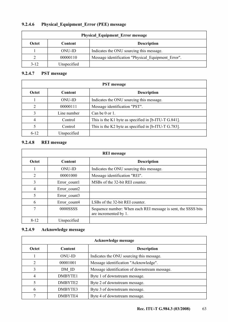
Rec. ITU-T G.984.3 (03/2008) 63
9.2.4.6 Physical_Equipment_Error (PEE) message
Physical_Equipment_Error message
Octet Content Description
1 ONU-ID Indicates the ONU sourcing this message. 2 00000110 Message identification "Physical_Equipment_Error".
3-12 Unspecified
9.2.4.7 PST message
PST message
Octet Content Description
1 ONU-ID Indicates the ONU sourcing this message. 2 00000111 Message identification "PST". 3 Line number Can be 0 or 1. 4 Control This is the K1 byte as specified in [b-ITU-T G.841]. 5 Control This is the K2 byte as specified in [b-ITU-T G.783].
6-12 Unspecified
9.2.4.8 REI message
REI message
Octet Content Description
1 ONU-ID Indicates the ONU sourcing this message. 2 00001000 Message identification "REI". 3 Error_count1 MSBs of the 32-bit REI counter. 4 Error_count2 5 Error_count3 6 Error_count4 LSBs of the 32-bit REI counter. 7 0000SSSS Sequence number: When each REI message is sent, the SSSS bits
are incremented by 1. 8-12 Unspecified
9.2.4.9 Acknowledge message
Acknowledge message
Octet Content Description
1 ONU-ID Indicates the ONU sourcing this message. 2 00001001 Message identification "Acknowledge". 3 DM_ID Message identification of downstream message. 4 DMBYTE1 Byte 1 of downstream message. 5 DMBYTE2 Byte 2 of downstream message. 6 DMBYTE3 Byte 3 of downstream message. 7 DMBYTE4 Byte 4 of downstream message.

64 Rec. ITU-T G.984.3 (03/2008)
Acknowledge message
Octet Content Description
8 DMBYTE5 Byte 5 of downstream message. 9 DMBYTE6 Byte 6 of downstream message.
10 DMBYTE7 Byte 7 of downstream message. 11 DMBYTE8 Byte 8 of downstream message. 12 DMBYTE9 Byte 9 of downstream message.
10 Activation method
10.1 Overview
10.1.1 Definitions The term "activation process" refers to the set of distributed procedures allowing an inactive ONU to join or resume operations on the PON. The activation process includes three phases: parameter learning, serial number acquisition and ranging.
During the parameter learning phase, the ONU, while remaining passive, acquires the operating parameters to be used in the upstream transmission. During the serial number acquisition phase, the OLT discovers a new ONU by its serial number and assigns the ONU-ID. To properly describe the third phase of the activation process, a few delay parameters are introduced below.
A time interval at the OLT between transmission of a downstream frame and reception of a corresponding upstream burst from the given ONU is referred to as the ONU's round-trip delay (RTD). The RTD is composed of the round-trip propagation delay, which is proportional to the ONU's fibre distance, and the ONU response time. The RTDs vary from one ONU to another. In order to ensure that the bursts from different ONUs are aligned at the boundaries of the same upstream GTC frame, each given ONU has to delay the transmission of an upstream burst beyond its regular response time. This extra time is referred to as ONU's equalization delay (EqD). The EqD for each given ONU is computed by the OLT based on the measurement of the corresponding RTD and is communicated to the ONU during the ranging phase of the Activation process.
The OLT may instruct the ONUs to use a specified common value of extra delay prior to completion of their individual ranging processes. This common value, which is communicated to the ONUs at the parameter learning phase, is referred to as pre-assigned delay (PrD).
To avoid collisions with the regular upstream bursts during serial number acquisition and ranging of the newly joining ONUs, the OLT must temporarily suppress upstream transmission by the in-service ONUs for the duration of the time interval when an arrival of upstream burst from a new ONU can be expected. Such a time interval is referred to as a quiet window.
10.1.2 Causal sequence of activation events The activation process is performed under the control of the OLT by means of exchange of upstream and downstream PLOAM messages. The outline of activation process events in their causal order is given below: – The ONU entering the activation process listens to the downstream transmission and attains
PSync and superframe synchronization. – The ONU waits for the Upstream_Overhead PLOAM message, optionally followed by the
Extended_Burst_Length PLOAM message periodically issued by the OLT.

Rec. ITU-T G.984.3 (03/2008) 65
– The ONU receives the PON operating parameters (the lengths and patterns of the burst mode overhead components, value of the pre-assigned delay, and initial optical power level) through the Upstream_Overhead and Extended_Burst_Length messages.
– The ONU announces its presence on the PON by responding to a broadcast serial number request periodically issued by the OLT with a Serial_Number_ONU message.
– The ONU adjusts its transmission optical power level using the absence of directed messages from the OLT as a negative acknowledgment.
– The OLT discovers the serial number of a newly connected ONU and assigns an ONU-ID to it using the Assign_ONU-ID message.
– The OLT issues a directed serial number request to a newly discovered ONU and accurately times the ONU's response.
– The OLT computes the individual equalization delay and communicates this equalization delay to the ONU using the Ranging_Time message.
– The ONU adjusts the start of its upstream GTC frame clock based on its assigned equalization delay.
– The ONU completes activation and start regular operation.
In the normal Operation state, the OLT monitors the phase and BER of the arriving upstream transmissions. Based on the monitored phase information, the OLT may re-compute and dynamically update the equalization delay for any ONU. Based on the monitored BER information, the OLT may instruct an ONU to dynamically adjust its optical power level.
10.2 Activation mechanism at the ONU
10.2.1 ONU activation states, timers and counters Seven ONU states are defined: O1 – Initial state O2 – Standby state O3 – Serial_Number state O4 – Ranging state O5 – Operation state O6 – POPUP state O7 – Emergency Stop state
To support the activation procedure, the ONU maintains two timers: TO1 – Serial number acquisition and ranging timer. Timer TO1 is used to abort an unsuccessful
activation attempt by limiting the overall time an ONU can sojourn in states O3 and O4. The recommended initial value of TO1 is 10 s.
TO2 – POPUP timer. Timer TO2 is used to assert a failure to recover from an intermittent LOS/LOF condition by limiting the time an ONU can sojourn in state O6. The recommended initial value of TO2 is 100 ms.
To autonomously adjust the optical power level while waiting for the ONU-ID assignment in the Serial_Number (O3) state, the ONU maintains a threshold on serial number requests (SN_Request_Threshold) and an associated counter. The details of the autonomous (ONU-activated) power-levelling procedure are given in clause 10.5.1.

66 Rec. ITU-T G.984.3 (03/2008)
10.2.2 ONU state specification The semantics of the seven ONU states is defined as follows: a) Initial state (O1) The ONU powers up in this state. LOS/LOF is asserted. Once downstream traffic is
received, LOS and LOF are cleared, the ONU moves to the Standby state (O2). b) Standby state (O2)
Downstream traffic is received by the ONU. The ONU waits for global network parameters. Once the Upstream_Overhead message is received, the ONU configures these parameters (e.g., delimiter value, power level mode and pre-assigned delay) and moves to the Serial Number state (O3).
c) Serial_Number state (O3)
By responding to the serial number requests sent out by the OLT, the ONU makes itself known to the OLT and allows the OLT to discover the ONU's serial number.
Once the ONU has responded to a serial number request, it waits for the unique ONU-ID assignment from the OLT. The ONU-ID is assigned using the Assign_ONU-ID message. Once assigned, the ONU moves to the Ranging state (O4).
The OLT may, at its discretion, use the Extended_Burst_Length message to communicate the extended overhead parameters to all the ONUs on the PON. If the ONU in Serial_Number state (O3) receives the Extended_Burst_Length message prior to receiving any serial number requests, it configures the type 3 preamble lengths according to the received values.
d) Ranging state (O4)
The upstream transmission from the different ONUs must be synchronized with the upstream GTC frame boundaries. In order to make the ONUs appear to be at an equal distance from the OLT, an equalization delay per ONU is required. This equalization delay is measured when the ONU is in the Ranging state. Once the ONU receives the Ranging_Time message, it moves to the Operation state (O5).
e) Operation state (O5) Once in this state, the ONU can send upstream data and PLOAM messages as directed by
the OLT. Additional connections can be established with the ONU as required while in this state. Once the network is ranged, and all the ONUs are working with their correct equalization delay, all upstream bursts will be synchronized together between all the ONUs. The upstream transmissions will arrive separately, each one in its correct location within the upstream GTC frame.
f) POPUP state (O6) The ONU enters this state from the Operation state (O5) following the detection of LOS or
LOF alarms. When entering the POPUP state (O6), the ONU immediately stops upstream transmission. As a result, the OLT will detect an LOS alarm for that ONU.
In the case of a break in the fibre ODN, there will be multiple ONUs that enter the POPUP state. Based on the network survivability scheme, one of the following options will be implemented:
If protection switching has been implemented, OLT can switch all the ONUs to the protection fibres. In this case, all the ONUs have to be re-ranged. To accomplish this goal, the OLT sends a broadcast POPUP message to the ONUs instructing them to move to the Ranging state (O4).

Rec. ITU-T G.984.3 (03/2008) 67
If there is no protection switching, or in case the ONU has internal protection capabilities, the OLT can send a directed POPUP message to the ONU instructing it to move to the Operation state (O5). Once the ONU is in the Operation state (O5), the OLT can test the ONU before returning it to full service. In particular, an encryption key switch event may have been scheduled while in the POPUP state (O6). To ensure graceful recovery in such a situation, the OLT should restart the key exchange and switch-over procedure with the ONU.
If the ONU does not recover from the of LOS or LOF alarms, it will not receive the POPUP message (broadcast or directed) and will move to the Initial state (O1), following time-out (TO2).
g) Emergency Stop state (O7) An ONU that receives a Disable_Serial_Number message with the 'disable' option moves to
the emergency stop state (O7) and shuts its laser off. During emergency stop, the ONU is prohibited from sending data in the upstream direction. If the ONU fails to move to the Emergency Stop state, that is, after the
Disable_Serial_Number message has been sent three times, the OLT continues to receive the ONU transmissions in the provided upstream bandwidth allocations, a DFi alarm is asserted in the OLT.
When the deactivated ONU's malfunction is fixed, the OLT may activate the ONU in order to bring it back to working condition. The activation is achieved by sending a Disable_Serial_Number message with the 'enable' option to the ONU. As a result, the ONU returns to Standby state (O2). All parameters (including serial number and ONU-ID) are re-examined.
10.2.3 ONU state diagram Figure 10-1 shows a graphic representation of the seven states of the ONU. The arrows in this figure show the state transitions described in the following clauses.

68 Rec. ITU-T G.984.3 (03/2008)
Initial State (O1)
ONU is switched on
Standby State (O2)ONU waits for network parameters
Serial Number State (O3)ONU waits for Serial Number
Request
Ranging State (O4)ONU waits for Ranging Request
Operation State (O5)ONU receives and transmits data
POPUP State (O6)ONU asserts LOS/LOF
Emergency Stop State (O7)ONU stops transmitting data in U/S
until enabled by OLT
ONU detects LOS/LOF
ONU detects LOS/LOF
ONU detects LOS/LOF
ONU receives Disable Request
ONU receives Disable Request
ONU receives Disable Request
ONU receives Disable Request
ONU detects LOS/LOF
ONU receives broadcast POPUP message
ONU receives directedPOPUP message
ONU receives Deactivation Request
ONU receives Deactivation Request
ONU receives downstreamframes − clears
LOS/LOF
ONU receivesUpstream_overhead
parameters
ONU receivesONU-ID
TO1 timer expires
ONU receivesEqualization
Delay
TO2 timer expires
ONU receives Enable Request
ONU receives Disable Request
TO1 timerexpires
ONU receives Deactivation Request
Figure 10-1 – The state diagram of the ONU
G.984.3_F10-1

Rec. ITU-T G.984.3 (03/2008) 69
10.2.4 ONU functional transitions Table 10-1 describes the functional behaviour of the ONU with respect to state transitions. The first column indicates the event that triggers a state change. The subsequent columns indicate the state the ONU transitions to as a function of the current state.
Table 10-1 – ONU activation states functional transitions
States of the ONU
Event Init (O1)
Standby (O2)
Serial_Number(O3)
Ranging (O4)
Operation (O5)
POPUP (O6)
Emer-gency Stop(O7)
ONU power up was last operational state (before power-down) O7?: => O7 else: => O1
– – – – – – –
ONU achieves PSync synchronization
The ONU clears LOS and LOF, then: => O2
– – – – – –
The ONU receives the upstream overhead parameters (PLOAMd = Upstream_ Overhead)
– The ONU configures its transmit parameters with the received values; starts timer TO1 then: => O3
– – – – –
The ONU receives the extended burst parameters (PLOAMd = Extended_Burst_ Length)
– – If no serial number request has been received, the ONU configures its type 3 preamble length with the received values; otherwise, no action.
– – – –
The ONU receives a serial number request (BW allocation structure with Alloc-ID = 254 PLOAMu = '1')
– – The ONU waits for minimum response time, plus pre-assigned delay, plus random delay before responding with a Serial_Number_ ONU message.
– – – –
The SN_Request_ Threshold is crossed
– – The ONU changes its power level (see clause 10.5.1).
– – – –
The ONU receives its ONU-ID (PLOAMd = Assign_ONU-ID)
– – The ONU configures its ONU-ID and then: => O4
– – – –

70 Rec. ITU-T G.984.3 (03/2008)
Table 10-1 – ONU activation states functional transitions
States of the ONU
Event Init (O1)
Standby (O2)
Serial_Number(O3)
Ranging (O4)
Operation (O5)
POPUP (O6)
Emer-gency Stop(O7)
The ONU receives a ranging request (BW allocation structure with Alloc-ID = ID of ONU to be ranged, PLOAMu = '1')
– – – The ONU waits for ONU minimum response time plus pre-assigned delay and responds with a Serial_ Number_ONU message.
In this state, a Ranging request looks just like regular PLOAM request, so ONU should respond with a PLOAM.
– –
The ONU receives a Change_Power_ Level message
– – – Match ONU-ID? – Change Tx optical power level.
Match ONU-ID? – Change Tx optical power level.
– –
The ONU receives its equalization delay (PLOAMd = Ranging_Time)
– – – ONU sets its equalization delay; stops timer TO1 and then: => 05
ONU sets its equalization delay.
– –
Timer TO1 expires – – => O2 => O2 – – –
Data request – – – – Match Alloc-ID? – Start Tx at specified time.
– –
The ONU receives deactivation message (PLOAMd = Deactivate_ONU-ID)
– – – Match ONU-ID? The ONU stops timer TO1 then: => O2
Match ONU-ID? => O2
Match ONU-ID? Stop timer TO2, then: => O2
–
ONU detects LOS or LOF
– => O1 The ONU stops the TO1 timer then: =>O1
The ONU stops the TO1 timer then: =>O1
The ONU ceases upstream transmission; starts TO2 timer and then: => O6
–
Broadcast POPUP message (PLOAMd = POPUP; with ONU-ID = 0xFF) is received by ONU
– – – – – The ONU stops timer TO2; starts timer TO1; and then: => O4
–
Directed POPUP message (PLOAMd = POPUP; with ONU-ID = ID of ONU) is received by ONU
– – – – – The ONU stops timer TO2 and then: => O5
–
Timer TO2 expires – – – – – => O1 –

Rec. ITU-T G.984.3 (03/2008) 71
Table 10-1 – ONU activation states functional transitions
States of the ONU
Event Init (O1)
Standby (O2)
Serial_Number(O3)
Ranging (O4)
Operation (O5)
POPUP (O6)
Emer-gency Stop(O7)
The ONU receives disable request (PLOAMd = Disable_Serial _Number with disable)
– Match SN? => O7
Match SN? The ONU stops timer TO1 and then => O7
Match SN? The ONU stops timer TO1 and then: => O7
Match SN? => O7
Match SN? The ONU stops timer TO2 and then: => O7
–
The ONU receives enable request (PLOAMd = Disable_Serial _Number with enable)
– – – – – – Match SN? => O2
10.2.5 ONU events
10.2.5.1 DS PLOAM message reception events Downstream PLOAM messages are sent three times by the OLT. The ONU generates a message receive event after receiving one valid message. A valid message is one with a valid CRC. The following is a list of the message reception events that occur during ONU activation. a) The receive event of Upstream_Overhead message. This event occurs only in the Standby state (O2). After successful reception of the
Upstream_Overhead message, the ONU learns the number of preamble bits, the value of the delimiter, the delay and power level parameters.
b) The receive event of Extended_Burst_Length message. This event occurs only in the Serial_Number state (O3) prior to any serial number requests.
After successful reception of the Extended_Burst_Length message, the ONU configures the type 3 preamble lengths for upstream transmission in pre-ranged and ranged states according to the parameters of the message. If an ONU receives the Extended_Burst_Length message after it received a serial number request while it still remains in state O3, the message is ignored.
c) The receive event of Assign_ONU-ID message. This event occurs only in the Serial_Number state (O3). When the serial number in the
Assign_ONU-ID message matches its own serial number, the ONU-ID is acquired and the ONU moves to Ranging state (O4).
d) The receive event of Ranging_Time message. This event occurs only in the Ranging state (O4) and Operation state (O5). When the
ONU-ID number in the PLOAM field matches its own ONU-ID, the equalization delay is acquired. When the ONU is in the Ranging state (O4), timer TO1 is stopped and transition of the ONU state to Operation state (O5) occurs.
e) The receive event of Change_Power_Level message with specific ONU-ID. This event occurs only in the Ranging state (O4) and Operation state (O5). When the
ONU-ID in the Change_Power_Level_message matches its own ONU-ID, the ONU adjusts (increase/reduce) its power level.

72 Rec. ITU-T G.984.3 (03/2008)
f) The receive event of broadcast POPUP message. This event occurs only in the POPUP state (O6). The transition of the ONU to the Ranging
state (O4) occurs. The timer TO2 is stopped and timer TO1 is started. g) The receive event of directed POPUP message. This event occurs only in the POPUP state (O6). When the ONU-ID number in the
PLOAM field matches its own ONU-ID, the ONU stops timer TO2 and transitions to Operation state (O5).
h) The receive event of Deactivate_ONU-ID message. This event occurs only in the Ranging state (O4), Operation state (O5) and POPUP state
(O6). When the ONU-ID number in the PLOAM field matches its own ONU-ID, the ONU stops transmitting in the upstream direction and transitions to Standby state (O2). If the ONU was in the Ranging state (O4), the timer TO1 is stopped as well. If the ONU was in the POPUP state (O6), the timer TO2 is stopped as well.
i) The receive event of Disable_Serial_Number message with disable parameter. This event occurs only in the Standby state (O2), Serial_Number state (O3), Ranging state
(O4), Operation state (O5) and POPUP state (O6). When the serial number in the Disable_Serial_Number message matches its own serial number, the ONU stops transmitting in the upstream direction and makes a transition to the Emergency Stop state (O7). If the ONU was in the Serial_Number state (O3) or Ranging state (O4), the timer TO1 is stopped as well. If the ONU was in POPUP state (O6), the timer TO2 is stopped as well.
j) The receive event of Disable_Serial_Number message with enable parameter. This event occurs only in the Emergency Stop state (O7). When the serial number in the
Disable_Serial_Number message matches its own serial number, the ONU transitions to the Standby state (O2).
10.2.5.2 DS bandwidth map reception events Special requests by the OLT to the ONU are conveyed in the PCBd section of the downstream frame in the form of the BWmap allocation structures. These requests require a real-time reaction from the ONU. Unlike the PLOAM messages above, these requests are sent only once to the ONU and a request receive-event is generated immediately. a) The serial number request receive event. This event occurs only in the Serial Number state (O3). The serial number request is
generated by the OLT with the following asserted fields: Alloc-ID = 254, PLOAMu = '1', StartTime = X, and StopTime = X + 12, where X is a starting time in bytes within the upstream GTC frame. The ONU, at its discretion, can send a longer SN transmission than defined by the StopTime for the purposes of optical power calibration, as long as the size of this additional transmission is 500 ns (78 bytes) or less.
Upon reception of the serial number request, the ONU waits for an ONU response time, random delay time plus the pre-assigned delay as indicated in the Upstream_Overhead message. Following this combined delay, it sends an SN response in the upstream direction at the X bytes. The serial number response is an upstream transmission containing the following fields: PLOu and PLOAMu with the Serial_Number_ONU message.
b) The ranging request receive event. This event occurs only in the ranging state (O4). The ranging request is generated by the
OLT with the following asserted fields: Alloc-ID field is equal to the ONU-ID of ONU to be ranged, PLOAMu='1', StartTime = X, StopTime = X + 12, where X is the starting time in bytes within the GTC frame that the ranging response is requested. The ONU, at its

Rec. ITU-T G.984.3 (03/2008) 73
discretion, can send a longer ranging transmission than defined by the StopTime for the purposes of optical power calibration, as long as the size of this additional transmission is 500 ns (78 bytes) or less.
Upon reception of the ranging request, the ONU waits for an ONU response time plus the pre-assigned delay as indicated in the Upstream_Overhead message. Following this combined delay, it sends a ranging response in the upstream direction at the X bytes. The ranging transmission is an upstream transmission containing the following fields: PLOu and PLOAMu with the Serial_Number_ONU message.
c) The receive event of data request via valid pointers. This event occurs only in the Operation state (O5). The data request is generated by the
OLT with the following asserted fields: Alloc-ID field is equal to the Alloc-ID of the traffic-bearing entity (a T-CONT or the OMCC) to be granted BW, StartTime = X, StopTime = Y, where X and Y are the appropriate start and stop time. The ONU transmits its US burst during these allocated time intervals. The ONU starts transmitting valid data at precisely the X byte and ceases transmission at the end of the Y byte.
10.2.5.3 Other events a) SN_Request_Threshold crossed. This event is generated when the ONU is in Serial_Number state (O3) and its serial number
request counter meets or exceeds the SN_Request_Threshold. See clause 10.5.1 for an explanation of this counter and the resulting action taken by the ONU. The proposed value for the SN_Request_Threshold is 10.
b) Timer TO1 expire. This event is generated when the activation procedure is not completed within a certain
time period. This event generates a state transition to Standby state (O2). The proposed value of TO1 is 10 s.
c) LOS or LOF detection. Either of these events causes the ONU to move to the Initial state (O1) except when it is in
Operation state (O5) or POPUP state (O6) or in the Emergency Stop state (O7). In addition, in the Serial Number (O3) and Ranging (O4) states, it will stop the timer TO1.
In Operation state (O5), this event causes the ONU state to move to the POPUP state (O6) after the timer TO2 is set to start.
d) Clear of LOS or LOF. This event causes the ONU state to move from the Initial state (O1) to Standby state (O2). e) Timer TO2 expire. This event is generated when the POPUP message is not received in the POPUP state
within a certain time period. This event generates a state transition to Initial state (O1). The proposed value of TO2 is 100 ms.
10.3 OLT support of the activation process
The OLT supports ONU activation by implementing an activation state machine of its own. The OLT activation state machine is composed of a common part and a separate instance of an ONU-specific part for each supported ONU.
10.3.1 OLT common part The OLT common part state machine performs the tasks that are common to or are impacting all of the ONUs on the PON. In particular, the OLT common part functionality includes broadcast of the PON overhead information (Upstream_Overhead and Extended_Burst_Length PLOAM messages),

74 Rec. ITU-T G.984.3 (03/2008)
quiet window creation for serial number acquisition and ranging phases, SN management, including ONU enabling/disabling by SN, and ONU-ID assignment. Overhead information broadcast and quiet window creation for serial number acquisition are performed periodically. The period may vary depending on whether or not the PON is fully populated and whether any of the ONUs have been recently deactivated or re-enabled after an emergency stop. Quiet window creation for ranging is performed per request of the ONU-specific part (see clause 10.3.2). ONU-ID assignment follows a successful discovery of an ONU by its SN.
The exact details of the OLT common part implementation are specific to a particular vendor. An informative example of the common part Operation states and state transitions can be found in clause IV.1.
10.3.2 ONU-specific part The ONU-specific part state machine performs the tasks that are specific to a particular ONU. It is instantiated on ONU-ID assignment and is released upon ONU-ID deactivation or ONU emergency stop. The ONU-specific part functionality includes tracking of the ONU's activation state and alarm status, as well as initial and in-service equalization delay measurement.
The exact details of the ONU-specific part implementation are left to the vendors. An informative example of the ONU-specific part operation states and state transitions can be found in clause IV.2.
10.3.3 Quiet window creation Once the OLT transmits a serial number request in a form of a bandwidth allocation structure addressed to all the ONUs in the Serial_Number state (broadcast) or to a specific ONU in the Ranging state (unicast), the arrival of a Serial_Number_ONU PLOAM response (during ranging) or multiple such responses (during serial number acquisition) may occur over a large time interval.
The exact timing of the ONU's response arrival depends not only on the parameters that are known to the OLT (the minimum ONU response time, 34 µs) or controlled by the OLT (the pre-assigned delay and the StartTime of the request), but also on the parameters that yet remain unknown for a pre-ranged ONU (the exact propagation delay and ONU response time) or are out of OLT's control (the random delay during the serial number acquisition).
The OLT is unable to deterministically avoid collisions between multiple SN responses from different ONUs in the Serial_Number state. However, it should indeed prevent collisions between Serial_Number_ONU PLOAM responses, on the one hand, and the regular upstream transmissions from the ONUs in the Operation state (O5), on the other hand. This is accomplished by creating a quiet window by means of withholding all the upstream bandwidth allocations from the ONUs in the Operation state for the entire duration of the time interval when an arrival of a Serial_Number_ONU PLOAM message can be expected.
The bandwidth allocations are effectively withheld for the duration of an entire upstream GTC frame when the OLT transmits an empty BWmap (using Blen = 0 in the PCBd) or fills the Alloc-ID fields of each BWmap allocation with the unassigned value of 255.
By using a non-zero value of the pre-assigned delay, the OLT can place the SN allocation in an arbitrary StartTime position within an empty or unassigned BWmap. See examples in clause 10.4.5 below.
10.3.4 Activation process failure detection The OLT should consider the activation process of a given ONU to be failed if, in response to each of the two consecutive ranging requests, one of the following events occurs: – No valid optical signal from the ONU is detected. – The upstream burst from the ONU cannot be delineated. – The upstream burst from the ONU is outside of the allocated quiet window.

Rec. ITU-T G.984.3 (03/2008) 75
– The initial 13 bytes of the delineated burst do not form a valid Serial_Number_ONU PLOAM message, or the CRC of that message is incorrect.
When the ONU activation failure is detected, the OLT stops the ranging attempts, asserts the SUFi alarm, and deactivates the ONU using the Deactivate_ONU-ID message.
10.3.5 Phase monitoring and updating equalization delay The ONU's upstream transmission is expected to arrive in a fixed time during the upstream GTC frame. The arrival phase of the ONU transmission may drift due to aging, temperature changes and other factors. In those cases, the equalization delay can be recalculated/updated from the drift of the upstream transmission. This allows small corrections to be made without having to re-range the ONU.
The change in the equalization delay will be equal to the drift time with opposite sign. Therefore, if the frame is early, the drift time will be added to the equalization delay. If the frame is late, the drift time will be subtracted from the equalization delay.
To avoid excessively frequent equalization delay updates and to ensure ONU compliance, the OLT maintains two drift thresholds. The lower threshold limits the allowed transmission deviation and allows to adjust the given ONU timing. When the drift exceeds the lower threshold, the new equalization delay value will be calculated by the OLT and will be transmitted to the ONU using the Ranging_Time PLOAM message. The OLT will also raise the drift of window (DOWi) condition for the given ONU. The upper threshold sets the maximum drift tolerance and protects the other ONUs on the PON. If the drift exceeds the upper threshold (an event which should not happen as long as the ONU complies with the equalization delay updates), the OLT should raise the transmission interference warning (TIWi) and deactivate the offending ONU.
The possible values of drift thresholds qualified by the G-PON upstream rate are given in the Table 10-2.
Table 10-2 – The suggested values of upstream transmission drift thresholds
Upstream interface rate [Gbit/s] DOWi threshold [bits] TIWi threshold [bits]
2.488 8 16 1.244 4 8
10.3.6 Fibre distance measurement In some situations, it is desirable to estimate the actual PON fibre distance from the OLT to a particular ONU. The OLT can implement the estimation procedure based on the round-trip measurement, using the value of the ONU's actual response time, which can be obtained via the OMCC. The estimate of the fibre distance may be obtained according to the following formula:
( ) 102×−= iii RTRTDFD
Here FDi is the estimated fibre distance in metres between the OLT and the given ONU i; RTDi is the round-trip delay in microseconds as measured by the OLT; RTi is the true ONU response time in microseconds, as reported by the ONU, and the numeric coefficient of 102 m/µs is a best fit value reflecting the range of refractive indices that G.652 fibres exhibit in the field. This method is capable of producing the estimate which is approximately ±1% accurate.
10.4 OLT and ONU timing relationships The material presented in this clause is based on the following definitions. 1) The start of the downstream frame is the moment of transmission/reception of the first byte
of the PSync field.

76 Rec. ITU-T G.984.3 (03/2008)
2) The start of the upstream GTC frame is the moment of transmission/reception (either actual or calculated) of the byte identified by the StartTime pointer of zero value.
3) The time of an upstream transmission is the moment of transmission/reception of the byte identified by the StartTime of the corresponding bandwidth allocation structure. For a non-contiguous transmission, this byte follows immediately the PLOu of the upstream burst. In particular, the time of serial number response is defined as the moment of transmission/reception of the first byte of the Serial_Number_ONU message.
10.4.1 Timing of ONU upstream transmissions All the ONU transmission events are referenced to the start of the downstream frame carrying the BWmap that contains the corresponding bandwidth allocation structures. Note, in particular, that an ONU transmission event is not referenced to the receipt of the corresponding bandwidth allocation structure itself, which may occur after a variable time into the downstream frame.
At all times, the ONU maintains a running Upstream GTC frame clock that is synchronized to the downstream GTC frame clock and offset by a precise amount. The amount of offset is the sum of two values: the ONU response time and the requisite delay, as shown in Figure 10-2.
Figure 10-2 – ONU timing diagram – General case
The ONU response time is a system-wide parameter that is chosen to give the ONU sufficient time to receive the downstream frame, including upstream bandwidth map, perform DS and US FEC as needed, and prepare an upstream response. The value of the ONU response time is 35±1 μs.
A general term requisite delay refers to the total extra delay that an ONU may be required to apply to the upstream transmission beyond its regular response time. The purpose of the requisite delay is to compensate for variation of propagation and processing delays of individual ONUs, and to avoid or reduce the probability of collisions between upstream transmissions. The value of requisite delay at the ONU is based on the delay equalization parameters specified by the OLT and changes with the state of the ONU as described below.

Rec. ITU-T G.984.3 (03/2008) 77
10.4.2 Timing relationships during serial number acquisition The following discussion is illustrated in Figure 10-3.
Figure 10-3 – Timing relationships during serial number acquisition
10.4.2.1 ONU upstream transmission An ONU enters the Serial_Number state (O3) upon learning the pre-assigned delay, specified in the Upstream_Overhead message. When the ONU in this state receives a serial number request, it should transmit a Serial Number Response in the form of a PLOAMu with the Serial_Number_ONU message.
Since the serial number request is a broadcast bandwidth allocation addressed to all ONUs in the Serial_Number state, more than a single ONU may respond to it, and a collision may occur when more than one serial number response arrives at the OLT at the same time. To reduce the probability of collision, the requisite delay in the Serial_Number state is obtained as a sum of the OLT-specified pre-assigned delay and the locally-generated random delay. This is shown in Figure 10-3. The random delay has the range of 0-48 μs and is expressed as an integral number of delay units, which are 32 bytes long. For each response to a serial number request, the ONU generates a new random number.
10.4.2.2 Size of the quiet window during serial number acquisition
The size of the quiet window during serial number acquisition is determined by the maximum variation of the unknown round-trip delay components: – 200 µs for the round-trip propagation delay, assuming the standard differential fibre reach
of 20 km; – 2 µs for ONU response time; – 48 µs for the ONU's random delay.
Summation of these terms gives a suggested duration of the quiet window during serial number acquisition of 250 μs.

78 Rec. ITU-T G.984.3 (03/2008)
10.4.3 Timing relationships during ranging The following discussion is illustrated in Figure 10-4.
Figure 10-4 – Timing relationships during ranging
10.4.3.1 ONU upstream transmission An ONU in the Ranging state (O4) responds to the ranging requests from the OLT with a ranging response in the form of a PLOAMu containing the Serial_Number_ONU message. A ranging request is a directed bandwidth allocation structure addressed to a specific ONU and, therefore, a collision between multiple ranging responses is not possible. The requisite delay in the Serial_Number state is, therefore, equal to the pre-assigned delay specified in the Upstream_Overhead message.
10.4.3.2 Size of the quiet window during ranging The size of the quiet window during ranging is determined by the maximum variation of the unknown round-trip delay components: – 200 µs for the round-trip propagation delay, assuming the standard differential fibre reach
of 20 km; – 2 µs for ONU response time.
Summation of these two terms gives a suggested duration of the quiet window during ranging of 202 µs.
10.4.3.3 Measuring the equalization delay There are two different yet equally valid methods for measuring equalization delay by the OLT. In one case, the OLT measures the equalization delay directly by timing the duration between the actual and desired SN response times, and adding the pre-assigned delay. The alternate method is to measure ONU's nominal RTD by timing the duration between the transmission of the start of the

Rec. ITU-T G.984.3 (03/2008) 79
frame that contains the SN request and the reception of the SN response, and then subtracting StartTime and pre-assigned delay. The desired equalization delay is then obtained using EqD(n) = Teqd –RTD(n), where Teqd is the 'zero-distance' EqD, which is the offset between the DS frame and the desired reception of the US frame at the OLT. The two methods are illustrated in Figure 10-5.
Once the ONU is supplied with its equalization delay value, it is considered synchronized to the beginning of the upstream GTC frame. The actual upstream data is transmitted within the interval specified by the allocation structure with respect to the beginning of the upstream GTC frame.
Figure 10-5 – Equalization delay measurements
10.4.3.4 PON distances greater than 20 km The nominal reach of a PON is 0 to 20 km and, in fact, the PHYs described in [ITU-T G.984.2] are only specified out to 20 km. Nevertheless, the G-PON protocol anticipates longer-reach PONs. Table 2a of [ITU-T G.984.2] specifies the maximum logical reach of a PON as 60 km and the maximum differential logical reach as 20 km. This means that the serving area of a PON with greater than 20-km reach is an annulus with an inner radius of X km and an outer radius of X+20 km, where 0 ≤ X ≤ 40 km. In either the 20 km case or the longer reach 'annulus' case situation, the maximum equalization delay or pre-assigned delay required is ~250 microseconds. However, implementers could optionally support equalization and pre-assigned delays up to ~625 microseconds such that unrestricted PON operation over the entire ultimate logical reach could be achieved.
The ranging process for longer-distance PONs is identical to that described above except that the fibre propagation delay is adjusted accordingly.

80 Rec. ITU-T G.984.3 (03/2008)
10.4.4 ONU upstream transmission timing during regular operation In the Operation state, the ONU maintains its upstream GTC frame clock synchronized with the downstream GTC frame clock and offset by the sum of the ONU response time and the assigned equalization delay specified by the OLT in the Ranging_Time message. This is shown in Figure 10-6. When the ONU receives a bandwidth allocation it transmits data starting at the upstream byte indicated in the StartTime field.
Figure 10-6 – Timing relationships in the Operation state
10.4.5 Quiet window implementation considerations When in the Serial Number and Ranging states, the ONUs transmit Serial_Number_ONU PLOAM messages at the request of the OLT. Because the OLT does not yet know the equalization delay (EqD) for these ONUs, it opens a quiet window to prevent collision between the requested SN responses and the regular upstream transmissions by the in-service ONUs.
Two examples of creating a quiet window are shown in Figure 10-7. Both examples focus on the SN acquisition and assume that the propagation delay is bounded by 100 µs while the ONU response time for different ONUs may vary, unbeknown to the OLT, within 35 ±1 µs range. Therefore, if the OLT transmits a downstream GTC frame with a specific BWmap at time to, coinciding with the start of downstream frame N, the earliest it can schedule the upstream GTC frame implementing this map is 236 µs later. The OLT's objective is to create a 250 µs-long quiet window starting at time to = to + 236 µs.
In case a, the OLT employs the pre-assigned delay of 202 µs, as specified by the Upstream_Overhead PLOAM message. The sole allocation structure of the BWmap transmitted with DS frame N is an SN request with StartTime = 0. The BWmap transmitted with DS frame N+1 is empty. As the minimum ONU response time is 34 µs, the front of the possible SN response transmission window (shaded area in Figure 10-7) is offset by at least 236 µs with respect to the start of the frame carrying the SN request.

Rec. ITU-T G.984.3 (03/2008) 81
In case b, the OLT does not use the delay pre-equalization technique. The BWmap supplied with DS frame N is empty, while the sole allocation structure of the BWmap transmitted with DS frame N+1 is an SN Request with StartTime offset of 77 µs, which corresponds to the byte value of 11976. The front of the possible SN response transmission window is offset by at least 111 µs with respect to the start of the frame carrying the SN request, and at least by 236 µs, with respect to the frame N.
Note that in both cases, frame N–1 has to provide a usual burst mode margin at the end of the BWmap, while frame N+2 may have to provide an extended margin at the start of the BWmap to accommodate possible unsolicited transmission of up to 78 bytes in addition to regular burst mode overhead.
Since each such quiet window affects at least two and possibly three consecutive bandwidth maps, the OLT must ensure that the impact of the quiet windows on the bandwidth- and jitter-sensitive traffic flows is minimized. This may be achieved, for example, by re-arranging the BWmaps and providing extra allocations to the affected Alloc-IDs immediately before and/or immediately after the quiet window.
If some information about ONU locations is available to the OLT, it may be able to create a smaller, better targeted and less intrusive quiet window, whose offset with respect to the start of the downstream frame depends on the fibre distance of the closest ONU, and the size, on the maximum differential fibre reach.

82 Rec. ITU-T G.984.3 (03/2008)
(a) Large pre-assigned delay
(b) Pre-assigned delay is not used
Figure 10-7 – Quiet window creation

Rec. ITU-T G.984.3 (03/2008) 83
10.5 Power levelling Due to the differences in the ODN losses for different ONUs, the OLT receiver must provide a high sensitivity and a large dynamic range for reception at high bit rates.
In order to relax the dynamic range of the OLT receiver, the transmitter power level of the ONUs experiencing a low ODN loss could be reduced in order to avoid overload of the OLT receiver. Similarly, in case of a high ODN loss, the transmitter power level of the ONUs could be increased.
Power levelling is the process whereby the ONU changes (increases or decreases) its transmit power in order to improve the signal-to-noise ratio at the OLT. There are two methods for initiating this process: ONU-activated and OLT-activated.
10.5.1 ONU-activated power levelling ONU-activated power levelling is initiated when the ONU responds to a specified number of SN requests without receiving an Assign_ONU-ID message from the OLT. This specified number of SN requests is called the SN_Request_Threshold and the recommended value is 10.
Initially, the ONU uses the Power Level mode specified in the Upstream_Overhead message. When the SN_Request_Threshold is crossed, the ONU increments its operating power level using modulo 3 (…,0,1,2,0,1,2,…) and resumes responding to SN requests. If the ONU again responds to a specified number of SN requests without response, it increments again its power level using modulo 3. This cycle is repeated until it receives either an Assign_ONU-ID message or a disable ONU message.
10.5.2 OLT-activated power levelling OLT-activated power levelling is initiated when the OLT determines that the ONU needs to change its power level. This determination could occur when the ONU is in Ranging state or Operation state and is indicated by an unacceptable upstream BER for a particular ONU. In this case, the OLT sends a directed Change_Power_Level message to the specific ONU to increase and/or decrease power level as needed.
11 Alarms and performance monitoring Alarms and performance monitoring encompasses mechanisms to detect link failure and monitor the health and performance of links. This clause does not cover such functions as station management, bandwidth allocation or provisioning functions.
11.1 Alarms The OAM functions installed in the ONU and OLT are shown in Figure 11-1. It also shows the notification signals between OLT and ONU.

84 Rec. ITU-T G.984.3 (03/2008)
Figure 11-1 – Alarms
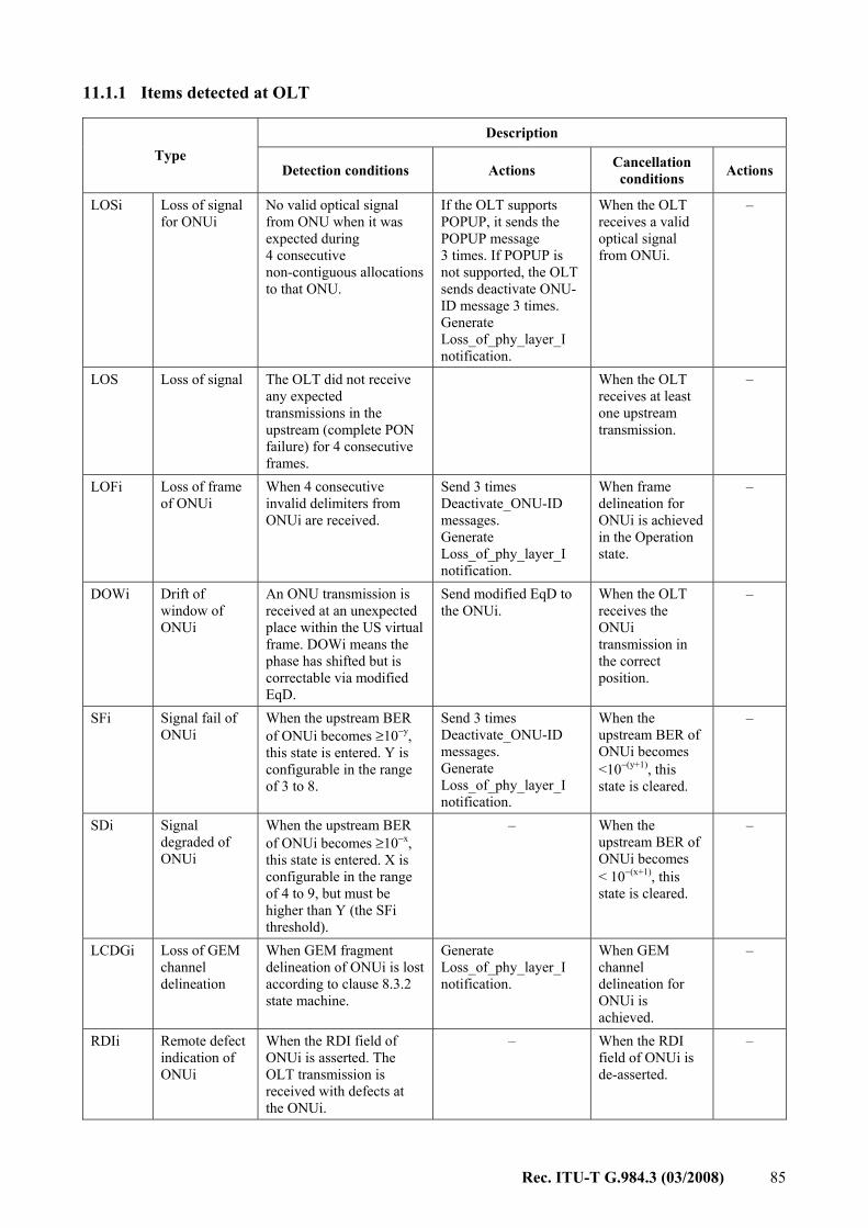
Rec. ITU-T G.984.3 (03/2008) 85
11.1.1 Items detected at OLT
Description Type
Detection conditions Actions Cancellation conditions Actions
LOSi Loss of signal for ONUi
No valid optical signal from ONU when it was expected during 4 consecutive non-contiguous allocations to that ONU.
If the OLT supports POPUP, it sends the POPUP message 3 times. If POPUP is not supported, the OLT sends deactivate ONU-ID message 3 times. Generate Loss_of_phy_layer_I notification.
When the OLT receives a valid optical signal from ONUi.
–
LOS Loss of signal The OLT did not receive any expected transmissions in the upstream (complete PON failure) for 4 consecutive frames.
When the OLT receives at least one upstream transmission.
–
LOFi Loss of frame of ONUi
When 4 consecutive invalid delimiters from ONUi are received.
Send 3 times Deactivate_ONU-ID messages. Generate Loss_of_phy_layer_I notification.
When frame delineation for ONUi is achieved in the Operation state.
–
DOWi Drift of window of ONUi
An ONU transmission is received at an unexpected place within the US virtual frame. DOWi means the phase has shifted but is correctable via modified EqD.
Send modified EqD to the ONUi.
When the OLT receives the ONUi transmission in the correct position.
–
SFi Signal fail of ONUi
When the upstream BER of ONUi becomes ≥10−y, this state is entered. Y is configurable in the range of 3 to 8.
Send 3 times Deactivate_ONU-ID messages. Generate Loss_of_phy_layer_I notification.
When the upstream BER of ONUi becomes <10−(y+1), this state is cleared.
–
SDi Signal degraded of ONUi
When the upstream BER of ONUi becomes ≥10−x, this state is entered. X is configurable in the range of 4 to 9, but must be higher than Y (the SFi threshold).
– When the upstream BER of ONUi becomes < 10−(x+1), this state is cleared.
–
LCDGi Loss of GEM channel delineation
When GEM fragment delineation of ONUi is lost according to clause 8.3.2 state machine.
Generate Loss_of_phy_layer_I notification.
When GEM channel delineation for ONUi is achieved.
–
RDIi Remote defect indication of ONUi
When the RDI field of ONUi is asserted. The OLT transmission is received with defects at the ONUi.
– When the RDI field of ONUi is de-asserted.
–

86 Rec. ITU-T G.984.3 (03/2008)
Description Type
Detection conditions Actions Cancellation conditions Actions
TF Transmitter failure
The OLT transmitter is declared in failure when there is no nominal backfacet photocurrent or when the drive currents go beyond the maximum specification.
– – –
SUFi Start-up failure of ONUi
The ranging of ONUi has failed n times (n = 2).
Send 3 times Deactivate_ONU-ID messages.
The ONU is ranged successfully.
–
DFi Deactivate failure of ONUi
The ONU does not react correctly after three Deactivate_ONU-ID or three Disable_Serial _Number messages. Note that the OLT can detect this condition only if it continues to provide upstream bandwidth allocations to the ONU.
– Cancelled by the operator.
–
LOAi Loss of acknowledge with ONUi
The OLT does not receive an acknowledgement from ONUi after a set of downstream messages that imply an upstream acknowledge.
Send 3 times Deactivate_ONU-ID messages. Generate Loss_of_phy_layer_I notification.
When the OLT receives an acknowledgement from the ONU.
–
DGi Receive dying-gasp of ONUi
When the OLT receives DG message from ONUi, DGi is asserted.
Ignore received alarms from this ONU. Generate Loss_of_phy_layer_I notification.
When the OLT receives a PLOAM message during ranging process.
–
LOAMi Loss of PLOAM for ONUi
When 3 consecutive PLOAM messages of ONUi are missing after the OLT issues send PLOAMu request for that ONU.
Send 3 times Deactivate_ONU-ID messages. Generate Loss_of_phy_layer_I notification.
When the OLT receives a PLOAM message corresponding to its PLOAM flag in the Operation state.
MEMi Message_Error message from ONUi
When the OLT receives an unknown message from ONUi.
– When the operator is informed.
–
MISi Link mismatch of ONUi
The OLT detects that the received PSTi and the transmitted PST are different.
– The OLT detects that received PSTi and the transmitted PST are the same.
–
PEEi Physical equipment error of ONUi
When the OLT receives a PEE message from the ONU.
Generate Loss_of_phy_layer_I notification.
When the OLT does not receive a PEE message from the ONUi in 3 s.

Rec. ITU-T G.984.3 (03/2008) 87
Description Type
Detection conditions Actions Cancellation conditions Actions
TIWi Transmission interference warning
In any sequential N frames, the drift of the ONU transmission exceeds the specified threshold.
Generate Loss_of_phy_layer_I notification.
In any sequential N frames, an ONU transmission is received within the specified threshold.
TIA Transmission interference alarm
An ONU turns on its laser at a time assigned to another ONU.
Generate Loss_of_phy_layer_I notification for affected ONUs.
The faulty ONU is corrected or eliminated.
LOKi Loss of key synch with ONUi
Key transmission from the ONU in response to Request_Key message fails three times.
Send 3 times Deactivate_ONU-ID messages. Generate Loss_of_phy_layer_I notification.
When the OLT receives a key from the ONU in the Operation state.
–
11.1.2 Items detected at ONU
Description Type
Detection conditions Actions Cancellation conditions Actions
LOS Loss of signal
No valid signal is received in the downstream.
Switch off laser. Generate Loss_of_phy_layer notification. Change state according to clause 10.
Valid optical signal. Move to Standby state.
LOF Loss of frame
When 5 consecutive invalid PSync from OLT are received.
Switch off laser. Generate Loss_of_phy_layer notification. Change state according to clause 10.
When 2 consecutive frames have correct PSync.
Move to Standby state.
SF Signal failed When the downstream BER becomes ≥10−y, this state is entered. Y is configurable in the range of 5 to 8.
– Set inactive when the downstream BER is <10−(y+1) .
–
SD Signal degraded
When the downstream BER becomes ≥10−x, this state is entered. X is configurable in the range of 6 to 9, but must be higher than Y.
– Set inactive when the downstream BER is < 10−(x+1) .
–
LCDG Loss of GEM channel delineation
When GEM fragment delineation is lost according to clause 8.3.2 state machine.
Generate Loss_of_phy_layer notification.
When GEM delineation is achieved.
–

88 Rec. ITU-T G.984.3 (03/2008)
Description Type
Detection conditions Actions Cancellation conditions Actions
TF Transmitter failure
The ONU transmitter is declared in failure when there is no nominal backfacet photocurrent or when the drive currents go beyond the maximum specification.
– – –
SUF Start-up failure
The ranging of this ONU has failed (see ranging protocol for exact condition).
– When ranging is successful.
–
MEM Message error message
When the ONU receives an unknown message.
– – –
DACT Deactivate ONU-ID
When the ONU receives Deactivate_ONU-ID message. It instructs the ONU to deactivate itself.
Switch off the laser and go to Standby state. Generate Loss_of_phy_layer notification.
Reception of Upstream_Overhead message.
Enable laser.
DIS Disabled ONU
When the ONU receives a Disable_Serial_ Number message with its own serial number and the enable flag equal to 0xFF. It stays in this state even after power off.
Switch off laser. Go to Emergency Stop state Generate Loss_of_phy_layer notification.
When the ONU receives a Disable_Serial_Number message with enable flag equal to 0x0F or when it receives a Disable_ Serial_Number message with its own serial number and the enable flag equal to 0x00.
Go to Initial state.
MIS Link mismatching
The ONU detects that the received PST and transmitted PST are different.
– The ONU detects that the received PST and transmitted PST are the same.
–
PEE Physical equipment error
When the ONU receives a PEE message.
Generate Loss_of_physical_ layer notification.
When the ONU does not receive a PEE message in 3 s.
RDI Remote defect indication in ONU
When the OLT transmission is received with defects at the ONU. The defects include general failures of the downstream data path, including excessive bit errors (after FEC), or corrupted overheads. Single bit errors are not considered defects.
Set RDI status bit in PLOu.
When the OLT transmission defect is resolved.
Clear RDI status bit in PLOu.

Rec. ITU-T G.984.3 (03/2008) 89
11.1.3 SD and SF thresholds specifications As part of the performance monitoring offered within the GTC protocol, signal fail (SF) and signal degrade (SD) conditions are calculated by the receive logic and declared as alarms.
Calculation of SF and SD conditions is done through counting of BIP violation over a certain time period and comparing the result to a predefined threshold. Clearing of SF and SD conditions is done in a similar manner, under the requirement that clearing should be done at one order of magnitude lower than the detect condition, e.g., if SD is declared at a BER of 10–5 it should be cleared at a BER of 10–6.
The detection time and detection thresholds are dependent upon the signal bit rate, the desired BER and the required probability of detection.
11.2 Performance monitoring
11.2.1 Items detected at OLT
Description Type
Detection conditions Actions
ERRi BIP error of ONUi
The received BIP-8 is compared with the calculated BIP-8 on the received stream. In case of a difference, ERRi counter is incremented.
The number of differing bits is accumulated in ERR. SDi and SFi are declared upon BER crossing a defined threshold.
REIi Remote error indication of ONUi
Once the ONU detects BIP errors, it sends upstream the number of errors inside the REI PLOAM message. When the received REIi message is different than zero, REIi counter is incremented.
REIi counter is incremented accordingly.
11.2.2 Items detected at ONU
Description Type
Detection conditions Actions
ERR BIP errors The received BIP-8 is compared with the calculated BIP-8 on the received stream. In case of a difference, ERR counter is incremented.
The number of differing bits is accumulated in ERR. SD and SF alarms are declared upon BER crossing a defined threshold.
11.2.3 Performance monitoring events Near-end PM are based on the defects and the BIP errors detected in a frame/transmission while Far-End PM are based on the received REI and RDI indications.
12 Security This clause discusses the data security issues that PON raises. It discusses the threat model that the security is intended to counter. It then discusses the basic key exchange and activation method.
12.1 Basic threat model The basic concern in PON is that the downstream data is broadcast to all ONUs attached to the PON. If a malicious user were to re-programme his ONU, then he could listen to all the downstream

90 Rec. ITU-T G.984.3 (03/2008)
data of all the users. It is this 'eavesdropping threat' that the PON security system is intended to counter. Other, more exotic threats are not considered practically important because, in order to attempt these attacks, the user would have to expend more resources than it would be worth.
Furthermore, the PON itself has the unique property in that it is highly directional. So any ONU cannot observe the upstream traffic from the other ONUs on the PON. This allows privileged information (such as security keys) to be passed upstream in the clear. While there are threats that could jeopardize this situation, such as an attacker tapping the common fibres of the PON, these again are not considered realistic, since the attacker would have to do so in public spaces, and would probably impair the very PON he is tapping.
12.2 Encryption system The encryption algorithm to be used is the advanced encryption standard (AES). It is a block cipher that operates on 16-byte (128-bit) blocks of data. It accepts 128, 192 and 256 bit keys. This algorithm is described in documents published by the National Institute of Standards and Technology (NIST) in the USA.
There are several modes of operation for this standard; however, only the 'counter' (CTR) mode shall be used [FIPS 81]. The cipher generates a stream of 16-byte pseudo-random cipher blocks which are exclusive-OR'ed with the input clear-text to produce the output of cipher-text. The cipher-text is exclusive-OR'ed with the same pseudo-random cipher blocks to regenerate the clear-text. Also, the key length is fixed at 128 bits. Larger keys may be supported in the future, but this usage is currently unspecified.
The counter mode uses a synchronized crypto-counter that is common to the OLT and all ONUs. The structure of this crypto-counter is as follows. The counter is 46 bits wide. The least significant 16 bits are the intra-frame counter, and the most significant 30 bits are the inter-frame counter.
The intra-frame counter is reset to zero at the beginning of the downstream frame (the first byte of the PCBd), and is incremented every four bytes. In the system with 2.488 Gbit/s downstream rate, the intra-frame counter runs from 0 to 9719.
The inter-frame counter is the same as the super-frame counter passed in the Ident field in the PCBd. The ONU implements a synchronized local counter and therefore has resilience to errors in this field.
The blocks of random cipher are aligned to the beginning of the datagram payloads.
Only the GEM frame/fragment payload is encrypted. The GEM header is not encrypted. Since the fragments need not be an integral number of code blocks, the last data block (1 to 16 bytes in length) is XORed with the most significant portion of the last AES cipher block (16 bytes in length). The excess portion of the last cipher block is discarded.
Note that the crypto-counter is aligned with the GTC downstream frame, but the AES cipher blocks are aligned to the data payloads. The relationship of these two sequences is illustrated in Figure 12-1. When a datagram is sent at the OLT or received at the ONU, the location of the first byte of its header is noted. The value of the crypto-counter at that byte position is used as the starting value of the cipher block counter for that datagram. For subsequent cipher blocks in that datagram, the counter is incremented by 1 for each block. This arrangement assures that the same value of counter is never used more than once.

Rec. ITU-T G.984.3 (03/2008) 91
Figure 12-1 – The relationship between the crypto-counter sequence and the cipher block sequence
The 46-bit block counter value drives the 128-bit input of the AES algorithm in the following way. The 46 bits are duplicated 3 times, producing a 138-bit sequence. The 10 most significant bits are then discarded. The resulting 128-bit number is then encrypted with the AES algorithm, producing 128 bits of random cipher, which is then XORed with the user payload data.
Note that the downstream encryption processing step is applied before FEC. However, the crypto-counter is derived from the frame as-transmitted, so the crypto-counter continues to run through the FEC parity bytes. The scrambling processing step is applied last.
12.3 Key exchange and switch-over We presume that the OLT and ONU have already configured a Port-ID for encrypted behaviour, and that they have established a key to use. Both the ONU and OLT store the key material in their active_key_registers, and it is this register that the encryption algorithm uses.
The key exchange is initiated by the OLT. The OLT does so by sending the Request_Key message in the PLOAM channel. The ONU responds by generating, storing and sending the key. The ONU stores the new key in the shadow_key_register. The ONU should generate a cryptographically unpredictable key. For guidance in achieving this, see [FIPS 140-2]. Because the PLOAM message is limited in length, the key is sent in two pieces, using the fragmentation field to indicate which part of the key is being sent. Both parts of the key are sent three times for extra redundancy. All ONU transmissions of a particular key have the same value of Key_Index, so that the OLT can definitively confirm that all transmissions are from the same key. The Key_Index is incremented for each key that the ONU generates upon request from the OLT.
If the OLT is unsuccessful in receiving either part of the key all three times it is transmitted, then the OLT will ask the ONU to generate another key by issuing a new Request_Key message. If the key transmission fails three times, then the OLT should declare a loss of key synchronization (LOKi) condition and deactivate the ONU.
Once the OLT successfully receives the key, it stores the validated key in its shadow_key_register. Now the system is prepared for key switch-over. The OLT chooses a frame number in the future to be the first frame to use the new key. It transmits the super-frame number of this frame to the ONU using the Key_Switching_Time message. This message is sent three times, and the ONU need only receive one correct copy to know the time to switch.

92 Rec. ITU-T G.984.3 (03/2008)
The Key_Switching_Time message requires an acknowledgment by the ONU. If, after three message loss of acknowledgment LOAi condition and deactivate the ONU.
At the beginning of the chosen frame, the OLT will copy the contents of the shadow_key_register into the active_key_register, and the ONU will copy its shadow_key_register into the active_key_register. In this way, both the OLT and ONU begin using the new key at precisely the same frame boundary for any new PDUs (frames) that they exchange.
Note that the AES algorithm requires the generation of a series of round keys based on a single key. This key scheduling operation takes time, and so it must be done in anticipation of the key switch. At the moment the key_switch bit is changed, both OLT and ONU must be ready to use the new key.
In some rare cases, an ONU may experience an intermittent LOS/LOF condition that interferes with a scheduled key switch. To ensure graceful recovery in such cases, it is recommended that the OLT restart the key exchange and switch-over procedure with an ONU that has been transitioned from the POPUP state (O6) to the Operation state (O5) immediately upon issuing a directed POPUP message to that ONU.
13 Forward error correction
13.1 Introduction
Forward error correction (FEC) is used by the transport layer in communication systems, and is based on transmitting the data in an encoded format. The encoding introduces redundancy, which allows the decoder to detect and correct the transmission errors. For example, for input BER of 10–4, the BER at the FEC decoder's output will drop to 10–15. By using the FEC technique, data transmission with a low error rate can be achieved, and retransmissions are avoided.
FEC results in an increased link budget by approximately 3-4 dB. Therefore, a higher bit rate and longer distance from the OLT to the ONUs can be supported, as well as a higher number of splits per single PON tree.
13.1.1 Reed-Solomon encoding Reed-Solomon (RS) code is a block-based code, which takes a data block of constant size and adds extra parity bytes at the end, thus creating a codeword. Using those extra bytes, the FEC decoder processes the data stream, discovers errors, corrects errors and recovers the original data. Reed-Solomon code is specified in [b-ITU-T J.81].
The most common RS code is RS(255,239), where a 255-byte codeword consists of 239 data bytes followed by 16 parity bytes. RS(255,239) is used in [b-ITU-T G.975] and [b-ITU-T G.709].
When using a block-based FEC, original data is preserved. Therefore, by ignoring the parity bytes, even if other the side does not support FEC, the original data can be processed.
Block-based FEC is not efficient for very high BER (e.g., for 10–3 BERs, decoding error will be generated).
13.1.2 FEC interoperability between OLT and ONU The FEC solution must support cases where the OLT communicates simultaneously with both FEC-supporting ONUs and non-FEC supporting ONUs.
13.1.2.1 Downstream interoperability – The OLT should support the capability to apply FEC encoding to its downstream data flow. – The OLT should have an option to disable FEC encoding on its downstream data flow.

Rec. ITU-T G.984.3 (03/2008) 93
– The FEC encoding status (on/off) should be sent to the ONUs using the FEC bit of the Ident field.
– An ONU may support the capability to apply FEC decoding to the incoming downstream data flow.
– An ONU that supports FEC decoding capability should apply FEC decoding and error-correction to the downstream data flow as long as the FEC encoding status in the Ident field is ON.
– An ONU that does not support FEC decoding should be capable of detecting the fact that the downstream flow is FEC-encoded and skip, i.e., not process, the parity bytes, fully retrieving the downstream data as received at the ONU, without applying FEC decoding nor trying to correct any transmission errors.
13.1.2.2 Upstream interoperability – An ONU may support the capability to apply FEC encoding to its upstream data. – If the FEC encoding capability is supported by the ONU, it should have an option to disable
FEC encoding on its upstream data flow. – The OLT sets the desired ONU FEC encoding status (on/off) using the Use_FEC bit in the
Flags field. While the desired FEC indication is transmitted with every allocation structure, the value of the Use_FEC bit should be the same for all the Alloc-IDs of any given ONU.
– An ONU that supports FEC encoding capability should respond to Use_FEC requests by encoding its upstream data, adding the parity bytes at the end of each codeword, and providing FEC ON indication in the Ind field of an upstream burst header. If the Use_FEC bit is not set, such an ONU should transmit data bytes in place of parity bytes, and provide FEC OFF indication in the Ind field of the upstream burst header.
– An ONU that does not support FEC encoding capability should ignore the Use_FEC requests, transmitting data bytes in place of parity bytes, and providing FEC OFF indication in the Ind field of the upstream burst header.
– The OLT should support the FEC decoding capability and apply FEC decoding on a per-ONU-burst basis, according to FEC indication in the Ind field of each upstream burst.
13.1.3 FEC statistics for performance monitoring While FEC decoding is being executed, some statistic functionality should be supported both upstream and downstream in order to monitor the transmission performance between OLT and ONU.
These FEC statistic measurements should include counting the following items: – Number of corrected bytes (i.e., bytes that have been corrected by FEC decoding). – Number of corrected codewords (i.e., codewords that have been corrected by FEC
decoding). – Number of uncorrectable codewords (i.e., codewords that have not yet been successfully
corrected by FEC decoding). – Number of total received codewords (i.e., codewords that have been received and involved
in the FEC decoding process). – FEC seconds (i.e., the number of seconds during which an uncorrectable codeword was
received).

94 Rec. ITU-T G.984.3 (03/2008)
13.2 Downstream FEC
13.2.1 DS Frame with FEC structure
13.2.1.1 Parity bytes When constructing the DS frame with FEC, the FEC parity bytes are inserted at the end of every codeword. When using RS(255,239), every 239 data bytes are followed with 16 parity bytes.
The PCBd part of the frame is included in the first codeword, i.e., the codeword begins with the PSync field. The second codeword starts after the 255th byte, the third codeword, after the 510th byte, and so on.
Note that since the DS bit rate is fixed, the FEC parity bytes are inserted instead of data bytes. Therefore, when FEC is used, less bandwidth is available for user data.
Note that the FEC encoding processing step is applied before scrambling.
Figure 13-1 – DS transmission with FEC parity bytes insertion
13.2.1.2 Shorter last codeword
The DS frame is divided into multiple 255-bytes codewords. When using 125-μs frames, less than 255 bytes will be left for the last codeword. The following describes the last codeword mechanism: – In order that the number of bytes in the last codeword will be equal to 255, extra 'zero'
bytes ('0' pad bytes) are added before the encoder, at the beginning of the last codeword. – The parity bytes are calculated. – The extra bytes ('0' pad bytes) are removed and the shorter codeword is transmitted. – When the frame is received at the ONU, the extra 'zero' bytes are reinserted before the
decoder, at the beginning of the last codeword. – Following the decoding process, the extra bytes are once again removed.
For a downstream data rate of 2.488 Gbit/s, the frame is 38 880 bytes long. Since only 120 bytes are left for the last codeword, 104 bytes are used as data bytes, 16 bytes are used as parity bytes, and 135 bytes are used for the '0' pad.

Rec. ITU-T G.984.3 (03/2008) 95
Figure 13-2 – Padding of the last codeword
13.2.2 FEC codeword synchronization
13.2.2.1 Frame synchronization at ONU The downstream framing-sequence is the physical synchronization field (PSync), which is based on the first 32 bits (0xB6AB31E0) of the PCBd in the frame's first codeword. Since block coding is used, these bits are not changed during the FEC encoding process, and are received unchanged at the ONU. Therefore, the ONU can continue using this sequence for frame synchronization.
Figure 13-3 – DS frame synchronization
13.2.2.2 Codeword synchronization Since all the codewords are arranged sequentially in the frame, no synchronization is needed for the codewords, i.e., once frame synchronization is achieved then, by implementing a 255-byte counter, codeword synchronization is achieved as well.
Once the codeword synchronization is achieved, each codeword is decoded (parity bytes are removed and corrected data is received) and the original downstream payload is reconstructed.

96 Rec. ITU-T G.984.3 (03/2008)
Figure 13-4 – Payload reconstruction at the FEC decoder
13.2.3 Downstream FEC on/off control
13.2.3.1 DS FEC indication bit The downstream FEC function can be activated/deactivated at the OLT by the OpS system. An in-band indication bit is used for notifying the ONUs about a change in the FEC status.
The DS frame contains a FEC indication bit located in the Ident field.
The FEC indication bit acts as follows: • '0' – FEC off. No FEC in the downstream frame. • '1' – FEC on. The downstream frame contains FEC parity bytes.
Note that the activation and deactivation of FEC is not meant to be an 'in-service' operation. The behaviour during switch-over is undefined, and likely to cause a momentary loss of data.
13.2.3.2 DS FEC on/off detection behaviour at ONU receiver
Since the line BER can be very high (≈10–6), the probability that an errored FEC indication bit is received at the ONU is relatively high. Therefore, a hysteresis mechanism is used for FEC on/off detection: • Default FEC status is 'off'. No DS FEC decoding is applied in the ONU. • Following 4 consecutive FEC 'on' indication bits, the FEC status is set to 'on'. DS FEC
decoding is activated in the ONU. • Following 4 consecutive FEC 'off' indication bits, the FEC status is set to 'off'. DS FEC
decoding is stopped in ONU.
13.3 Upstream FEC
13.3.1 Upstream transmission with FEC structure
13.3.1.1 Parity bytes When constructing the US transmission with FEC, the FEC parity bytes are inserted at the end of every codeword. When using RS(255,239), every 239 data bytes are followed with 16 parity bytes.

Rec. ITU-T G.984.3 (03/2008) 97
The delimiter and preamble fields of the PLOu section of the ONU OH are not included in the first codeword, i.e., the codeword begins with the BIP byte.
Figure 13-5 – US transmission with FEC parity bytes insertion
All allocations on a particular ONU will have the same FEC status. Contiguous allocations will be encoded as a single block of data, and have only one shortened last codeword. The start pointers cannot point to parity byte locations. As a consequence, the stop pointers cannot point to the first 15 parity byte locations or the last data byte before a parity byte location. These restrictions are illustrated in Figure 13-6.
Figure 13-6 – Pointer restrictions in the case of contiguous allocations with FEC
If, with upstream FEC enabled, the OLT violates the pointer restrictions, the ONU's behaviour is undefined.
G.984.3_F13-6

98 Rec. ITU-T G.984.3 (03/2008)
As long as FEC is enabled in US transmission, the size of a non-contiguous allocation as well as the size of the last allocation in a group of contiguous allocations must be at least 18 bytes. The minimum allocation accommodates a DBRu-only transmission along with 16 parity bytes.
If the ONU receives a FEC-enabled allocation and, given the need to insert 16 parity bytes, finds its size insufficient to accommodate the minimal-size GEM frame transmission or the items requested via the Flags field (PLOAMu and DBRu), then the ONU may optionally ignore the allocation or try to assist the OLT in graceful recovery by sending an all-zero-octets sequence of the allocated size.
Note that the FEC encoding processing step is applied before scrambling.
13.3.1.2 Shorter last codeword The original transmission is divided into 239 bytes codewords. In most cases, less than 239 bytes will be left for the last codeword. The following describes the last codeword mechanism: • In order that the number of bytes in the last codeword will be equal to 239, extra 'zero'
bytes ('0' pad bytes) are added before the encoder, at the beginning of the last codeword. • The parity bytes are calculated. • The extra bytes are removed and the shorter codeword is transmitted. • The transmission is received at the OLT. • The extra 'zero' bytes are reinserted before the decoder, at the beginning of the last
codeword. Since the transmission size is known to the OLT in advance, it can easily calculate the number of those 'zero' bytes.
• Following the decoding process, the extra bytes are once again removed.
Decoded window: Data
Bytes Data Bytes Data BytesONU OH
DataBytes Data Bytes Data BytesONU OH Data
Bytes
Output Window
DataBytes Data Bytes Parit
y Data Bytes ParityONU OH Parit
yParit
y Window before
Decoder
DataBytes Data Bytes Parit
y Data Bytes ParityONU OH Parit
yParit
y Encoded Window:
Window before
Encoder Data
Bytes Data Bytes Data BytesONU OH
DataBytes Data Bytes Data BytesONU OH Data
BytesOriginal Window:
Data Bytes '0' Pad
'0' Pad Data Bytes
'0' Pad Data Bytes
Data Bytes '0' Pad
OLT RX
DataBytes Data Bytes Parit
y Data Bytes Parity
ONU OH Parity
Data Bytes
Parit y Tx ONT
Window:
DataBytes Data Bytes Parit
y Data Bytes Parity
ONU OH Parity
Data Bytes
Parit y Rx Window at
OLT
ONU TX
Figure 13-7 – US transmission with FEC structure
Note that if less than 17 bytes are available for the last codeword, then all-zeroes should be sent.
G.984.3_F13-7

Rec. ITU-T G.984.3 (03/2008) 99
13.3.1.3 ONU transmission size The transmission size, defined in the US BWmap in the PCBd part of the downstream frame, is based on the encoded transmission without the '0' pad bytes. The OLT should take the usage of FEC into account in the calculation of the bandwidth map, and strive to allocate an integral number of FEC blocks for those ONUs that are utilizing FEC.
13.3.2 FEC codeword synchronization
13.3.2.1 Transmission synchronization The preamble and delimiter fields in PLOu section of the ONU upstream burst are used for upstream transmission synchronization. These fields are not changed during the FEC encoding process, i.e., received unchanged at the OLT. Therefore, the OLT can continue using the preamble and delimiter for transmission synchronization.
Since all codewords are arranged sequentially in the transmission, no synchronization is needed over the codewords. Once transmission synchronization is achieved, the exact location of each codeword is known, and codeword synchronization is achieved (255 bytes per codeword).
13.3.2.2 Delimiter errors Due to high BER, the probability for receiving errors in the delimiter is high. To achieve robust burst delineation in the presence of errors, the delimiter should be represented by a large enough bit-pattern with optimal autocorrelation properties. According to the model presented in Appendix I of [ITU-T G.984.2], a 20-bit delimiter can tolerate up to four errored bits.
13.3.3 US FEC on/off
13.3.3.1 US FEC indication bit The upstream FEC function of the ONU can be activated/deactivated by the OpS system via the OLT. An in-band indication bit is used by the ONU to notify the OLT of a change in the FEC status.
The OLT sets the desired ONU FEC encoding status (on/off) using the Use_FEC bit in the Flags field. Note that all allocations in any ONU must use the same FEC status. The ONU should act immediately on the Use_FEC bit.
The FEC indication bit acts as follows: • '0' – Off. No FEC in US transmission. • '1' – On. US transmission contains parity bytes.
The indication bit serves as a confirmation that the ONU has complied with the Use_FEC request.
13.3.3.2 US FEC on/off detection behaviour at OLT The OLT knows a priori the FEC status of the upstream burst since it controls this via the Flags field. Hence, if FEC is requested, the OLT should then expect FEC to be included in the upstream transmission. The content of the FEC indication bit is a piece of auxiliary information that can be used to confirm the FEC status of the ONU.
13.4 ONU activation transmissions No upstream FEC will be applied while the ONU is outside of the normal Operation state. This is required due to the short length of the special transmissions that occur in the non-operating states and to the rare occurrence of special transmissions.

100 Rec. ITU-T G.984.3 (03/2008)
14 OMCI transport mechanism The ONU management and control interface is an OAM service that provides a standard way to discover ONU capabilities, and to manage and control them. The G-PON OMCI is defined in [b-ITU-T G.984.4].
14.1 OMCI transport schema As described in [b-ITU-T G.984.4], the OMCI operates on a dedicated bidirectional virtual connection between the management station and the ONU. The management station can be located in the OLT itself, or in a network element farther into the network. In the latter case, then the virtual connection must reach from the ONU to the network element.
To transport the OMCI virtual connection over the G-PON link, the OLT configures a dedicated GEM Port-ID using the appropriate PLOAM message.
The OMCI primitive data units are 48-bytes in length. The 48-byte payloads are encapsulated into GEM frames with a header containing the configured OMCI 12-bit Port-ID. These frames are transported over the G-PON in the GTC payload using the default Alloc-ID in the upstream.
14.2 OMCI adapters The OMCI adapter at the ONU is responsible for filtering and de-encapsulating frames in the downstream, and encapsulating the PDUs in the upstream. The 48-byte PDUs are handed off to the logic that implements the OMCI functions.
The OMCI adapter at the management station is responsible for filtering and de-encapsulating frames in the upstream. Many concurrent channels must be supported, and these can be of mixed types. It is also responsible for encapsulating the 48-byte PDUs from the OMCI control logic in the appropriate format for transport to the ONU.

Rec. ITU-T G.984.3 (03/2008) 101
Annex A
Implementers' guide for Recommendation UIT-T G.984.3 (This annex forms an integral part of this Recommendation)
Summary This annex is an informative addendum to this Recommendation intended to clarify G-PON GTC-related aspects and enable easier interoperability. This annex includes examples for some of the main data processing in the G-PON GTC level.
Clauses A.2-A.5 provide example golden vectors for some of the GTC functionality, including AES, FEC and scrambling.
Clause A.6 shows an example of ONU activation process.
Clause A.7 contains examples for PLOAM messages.
Clause A.8 illustrate the order of processes in a GTC transmit flow.
Source This implementers' guide was agreed by ITU-T Study Group 15 on 17 February 2006.
A.1 Introduction This implementers' guide describes basic functions for interoperability between the OLT and ONU on G-PON GTC. This guide aims to clarify descriptions in the main body of this Recommendation. The implementers' guide does not request any modifications for the Recommendation, but provides comments and clarifications on the Recommendation to enhance readability for implementers.
A.2 AES mechanism and golden vectors
A.2.1 Key_Switching_Time message structure See clause 9.2.3.19.
A.2.2 AES encryption golden vector The AES encryption/decryption procedure depends on the encryption key used, on the current super-frame counter and on the byte in frame location of the GEM fragments. The following example includes 3 consecutive GEM fragments for the same ONU, i.e., all use the same encryption key. The sequence parameters are the following: • The key in use is: 0x112233445566778899AABBCCDDEEFF00 (in 'encryption key'
message – key byte 0 is '11', key byte 15 is '00'). • The super-frame counter value is: 0x3DCAE120. • The first byte of the first fragment is the 158th byte in the GTC frame.
The example consists of the plain-text vector and the cipher-text vector, and a diagram which demonstrates the parameters used for the AES procedure (e.g., byte number, crypto counter value). The numbers in the example are given in hexadecimal representation. The bold numbers represent GEM header bytes.
The plain text: B4 9A 12 D0 73 00 01 02 03 04 05 06 07 08 09 0A
0B 0C 0D 0E 0F 10 11 12 13 14 15 16 17 18 19 1A
1B 1C 1D 1E 1F 20 21 22 B6 CA 12 C0 4A AA BB CC
DD EE FF B6 5A 12 C1 BB 11 22 33 44 55 66 77 88

102 Rec. ITU-T G.984.3 (03/2008)
99 AA BB CC DD EE FF
The cipher text: B4 9A 12 D0 73 3A FB 97 EE FC BC C1 6B 6C 57 1A
A4 FF 7A C3 AD 6C 85 28 5A 57 F8 9E 7A 36 07 CA
8A CE 45 0A 97 A9 74 5A B6 CA 12 C0 4A 8B 5F 94
E4 8F 34 B6 5A 12 C1 BB 9D F4 F4 15 F6 A4 3C D0
30 0F F6 92 88 EE 54
Figure A.2-1 demonstrates the relationship between the data and the crypto-counter:
Key 0x112233445566778899AABBCCDDEEFF00Superframe Counter 0x3DCAE120
Byte Number within GTC Frame 158 159 160 161 162 163 164 165 166 167 168 169 170 171 172 173 174Crypto-Counter [hexadecimal]Plaintext Data B4 9A 12 D0 73 00 01 02 03 04 05 06 07 08 09 0A 0BCipher Block CounterEncypted Data 3A FB 97 EE FC BC C1 6B 6C 57 1A A4
Byte Number within GTC Frame 175 176 177 178 179 180 181 182 183 184 185 186 187 188 189 190 191Crypto-Counter [hexadecimal]Plaintext Data 0C 0D 0E 0F 10 11 12 13 14 15 16 17 18 19 1A 1B 1CCipher Block CounterEncypted Data FF 7A C3 AD 6C 85 28 5A 57 F8 9E 7A 36 07 CA 8A CE
Byte Number within GTC Frame 192 193 194 195 196 197 198 199 200 201 202 203 204 205 206 207 208Crypto-Counter [hexadecimal] 2FPlaintext Data 1D 1E 1F 20 21 22 B6 CA 12 C0 4A AA BB CC DD EE FFCipher Block CounterEncypted Data 45 0A 97 A9 74 5A 8B 5F 94 E4 8F 34
Byte Number within GTC Frame 209 210 211 212 213 214 215 216 217 218 219 220 221 222 223 224 225Crypto-Counter [hexadecimal] 38Plaintext Data B6 5A 12 C1 BB 11 22 33 44 55 66 77 88 99 AA BB CCCipher Block CounterEncypted Data 9D F4 F4 15 F6 A4 3C D0 30 0F F6 92
Byte Number within GTC Frame 226 227 228Crypto-Counter [hexadecimal]Plaintext Data DD EE FFCipher Block CounterEncypted Data 88 EE 54
36 37
38
34 35
30 31 32 33
2A 2B
2B 2C 2D 2E 2F
34
34
27 28
28 29 31
27
27 28 29
Figure A. 2-1 – Relationship between data and crypto-counter; no FEC
A.2.3 AES with DS FEC golden vector The following example demonstrates encryption of 2 GEM fragments, when FEC is enabled on the downstream. Both GEM fragments are destined for the same ONU, i.e., they use the same encryption key.
The sequence parameters are: • The key in use is: 0x112233445566778899AABBCCDDEEFF00 (in 'encryption key'
message – key byte 0 is '11', key byte 15 is '00'). • The super-frame counter value is: 0x3DCAE120. • The first byte of the first fragment is the 220th byte in the GTC frame.

Rec. ITU-T G.984.3 (03/2008) 103
The example consists of the plain-text vector and the cipher-text vector and a diagram which demonstrates the parameters used for the AES procedure (e.g., byte number, crypto counter value). The numbers in the example are given in hexadecimal representation. The bold numbers represent GEM header bytes. Parity bytes are marked as PP and their value is not given since only a part of the codeword is shown in the example.
The plain text: B7 4A 12 D0 21 00 01 02 03 04 05 06 07 08 09 0A 0B
0C 0D 0E PP PP PP PP PP PP PP PP PP PP PP PP PP PP
PP PP 0F 10 11 12 13 14 15 16 17 18 19 1A 1B 1C 1D
B6 5A 12 C1 BB 11 22 33 44 55 66 77 88 99 AA BB CC
DD EE FF
The cipher text: B7 4A 12 D0 21 0F DA 75 62 82 60 A4 8E A0 53 1B 6D
CA 53 9B PP PP PP PP PP PP PP PP PP PP PP PP PP PP
PP PP B6 0C 48 B2 74 5A 7E 95 C1 F3 63 BD 63 5C DF
B6 5A 12 C1 BB 58 F1 4C 22 75 38 D0 32 C8 90 28 6E
71 84 ED
It is important to note that the parity bytes are not encrypted.
Figure A.2-2 demonstrates the relation between the data and the crypto-counter:

104 Rec. ITU-T G.984.3 (03/2008)
Key 0x112233445566778899AABBCCDDEEFF00Superframe Counter 0x3DCAE120
Byte Number within GTC Frame 220 221 222 223 224 225 226 227 228 229 230 231 232 233 234 235 236Crypto-Counter [hexadecimal] 36Plaintext Data B7 4A 12 D0 21 00 01 02 03 04 05 06 07 08 09 0A 0BCipher Block CounterEncypted Data 0F DA 75 62 82 60 A4 8E A0 53 1B 6D
Byte Number within GTC Frame 237 238 239 240 241 242 243 244 245 246 247 248 249 250 251 252 253Crypto-Counter [hexadecimal] 3FPlaintext Data 0C 0D 0E PP PP PP PP PP PP PP PP PP PP PP PP PP PPCipher Block CounterEncypted Data CA 53 9B PP PP PP PP PP PP PP PP PP PP PP PP PP PP
Byte Number within GTC Frame 254 255 256 257 258 259 260 261 262 263 264 265 266 267 268 269 270Crypto-Counter [hexadecimal]Plaintext Data PP PP 0F 10 11 12 13 14 15 16 17 18 19 1A 1B 1C 1DCipher Block Counter 36
Encypted Data PP PP B6 0C 48 B2 74 5A 7E 95 C1 F3 63 BD 63 5C DF
Byte Number within GTC Frame 271 272 273 274 275 276 277 278 279 280 281 282 283 284 285 286 287Crypto-Counter [hexadecimal]Plaintext Data B6 5A 12 C1 BB 11 22 33 44 55 66 77 88 99 AA BB CCCipher Block CounterEncypted Data 58 F1 4C 22 75 38 D0 32 C8 90 28 6E
Byte Number within GTC Frame 288 289 290Crypto-Counter [hexadecimal] 47Plaintext Data DD EE FFCipher Block CounterEncypted Data 71 84 ED
47
48
43 44 45 46
3D 3E
3F 40 41 42 43
36
37
36
37 38 39 3A
3B 3C
43
43
Figure A. 2-2 – Relation between data and crypto-counter; FEC enabled
A.3 FEC encoding golden vector The G-PON FEC is based on the RS(255,239) as used in [b-ITU-T G.975] and [b-ITU-T G.709].
The implementation of the FEC encoder should be the functional equivalent of the IIR model depicted below. In this IIR model, all the multipliers and adders are operations in GF(256) and the primitive polynomial is: X8+X4+X3+X2+1.
Figure A. 3-1 – IIR model for FEC encoder
The 'data_in' are the payload symbols (bytes). Initial value for p0-p15 is 0x00.
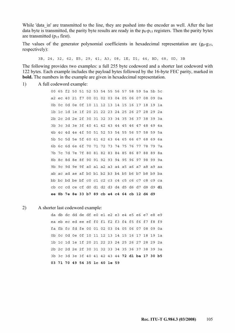
Rec. ITU-T G.984.3 (03/2008) 105
While 'data_in' are transmitted to the line, they are pushed into the encoder as well. After the last data byte is transmitted, the parity byte results are ready in the p0-p15 registers. Then the parity bytes are transmitted (p15 first).
The values of the generator polynomial coefficients in hexadecimal representation are (g0-g15, respectively): 3B, 24, 32, 62, E5, 29, 41, A3, 08, 1E, D1, 44, BD, 68, 0D, 3B
The following provides two examples: a full 255 byte codeword and a shorter last codeword with 122 bytes. Each example includes the payload bytes followed by the 16-byte FEC parity, marked in bold. The numbers in the example are given in hexadecimal representation. 1) A full codeword example:
00 65 f2 50 51 52 53 54 55 56 57 58 59 5a 5b 5c
a2 ec 40 21 f7 00 01 02 03 04 05 06 07 08 09 0a
0b 0c 0d 0e 0f 10 11 12 13 14 15 16 17 18 19 1a
1b 1c 1d 1e 1f 20 21 22 23 24 25 26 27 28 29 2a
2b 2c 2d 2e 2f 30 31 32 33 34 35 36 37 38 39 3a
3b 3c 3d 3e 3f 40 41 42 43 44 45 46 47 48 49 4a
4b 4c 4d 4e 4f 50 51 52 53 54 55 56 57 58 59 5a
5b 5c 5d 5e 5f 60 61 62 63 64 65 66 67 68 69 6a
6b 6c 6d 6e 6f 70 71 72 73 74 75 76 77 78 79 7a
7b 7c 7d 7e 7f 80 81 82 83 84 85 86 87 88 89 8a
8b 8c 8d 8e 8f 90 91 92 93 94 95 96 97 98 99 9a
9b 9c 9d 9e 9f a0 a1 a2 a3 a4 a5 a6 a7 a8 a9 aa
ab ac ad ae af b0 b1 b2 b3 b4 b5 b6 b7 b8 b9 ba
bb bc bd be bf c0 c1 c2 c3 c4 c5 c6 c7 c8 c9 ca
cb cc cd ce cf d0 d1 d2 d3 d4 d5 d6 d7 d8 d9 d1
ee 8b 7e 8e 33 b7 89 cb e4 c4 64 cb 12 d4 d9
2) A shorter last codeword example: da db dc dd de df e0 e1 e2 e3 e4 e5 e6 e7 e8 e9
ea eb ec ed ee ef f0 f1 f2 f3 f4 f5 f6 f7 f8 f9
fa fb fc fd fe 00 01 02 03 04 05 06 07 08 09 0a
0b 0c 0d 0e 0f 10 11 12 13 14 15 16 17 18 19 1a
1b 1c 1d 1e 1f 20 21 22 23 24 25 26 27 28 29 2a
2b 2c 2d 2e 2f 30 31 32 33 34 35 36 37 38 39 3a
3b 3c 3d 3e 3f 40 41 42 43 44 72 d1 ba 17 30 b5
03 71 70 49 54 35 1c 40 1e 59

106 Rec. ITU-T G.984.3 (03/2008)
A.4 Scrambler diagram
X^0 X^7
Figure A. 4-1 – Scrambler block diagram
Initial condition: Every downstream frame, after the PSync field, the scrambler is initialized to all-ones.
The 127-bit scrambler sequence is given below in binary and hexadecimal representation (last 3 binary bits are without a hexadecimal representation):
1111 1110 0000 0100 0001 1000 0101 0001 1110 0100 0101 1001 F E 0 4 1 8 5 1 E 4 5 9
1101 0100 1111 1010 0001 1100 0100 1001 1011 0101 1011 1101 D 4 F A 1 C 4 9 B 5 B D
1000 1101 0010 1110 1110 0110 0101 010 8 D 2 E E 6 5
A.5 A downstream frame example The purpose of the downstream frame test vectors is to provide: – Examples for CRC on PLOAM, PLend and US BW map access. – An example of traffic payload mapping into GEM fragments. – An example of frame scrambling.
The example includes the first 138 bytes of a GTC downstream frame. This includes the PCBd and two GEM fragments (zero ATM portion). The PCBd includes a 'Key_Switching_Time' PLOAM message and two US BW map accesses.
The detailed parameters for the different fields are: – Ident field: Super-frame counter is 0x00051276 and FEC ind is 0. – PLOAM message: 'Key_Switching_Time' (type 0x13) message addressed to ONU-ID 0x12

Rec. ITU-T G.984.3 (03/2008) 107
– US BW map:
Alloc-ID Flags StartTime StopTime
Access 1 0x10 0x000 0x1000 0x1500
Access 2 0x150 0x400 0x1600 0x1700 – GEM fragments:
1) First Fragment: 64 byte Ethernet packet where: DA=FF-FF-FF-FF-FF-FF, SA=00-0E-7F-5F-F1-DF. 2) Second fragment: Unstructured data.
NOTE 1 – AES is not applied to GEM fragments. NOTE 2 – BIP field is NA in the example.
Frame before scrambling:
B6 AB 31 E0 00 05 12 76 12 13 21 01 05 00 00 00 00 00 00 00 CA 55 00 20 00 AE 00 20 00 AE 01 00 00 10 00 15 00 AE 15 04 00 16 00 17 00 F2BIP
B2 AA 31 CD 74 FF FF FF FF FF FF 00 0E 7F 5F F1 DF 08 06 00 01 08 00 06 04 00 01 00 0E 7F 5F F1 DF C0 A8 01 84 00 00 00 00 00 00 C0 A8 01
41 00 00 00 00 00 00 00 00 00 00 00 00 00 00 00 00 00 00 F9 A6 DF 13 B7 8A 12 CD 2D 76 12 05 72 08 11 77 06 08 74 10 20 73 03 14 81 01 21
GEM HeaderEthernet Packet
Ethernet PacketData
Access 1 Access 2
FCS
DA SA
GEM Header
Psync Ident PLOAM Plend
Frame after scrambling:
B6 AB 31 E0 FE 01 0A 27 F6 4A F5 FB 19 49 B5 BD 8D 2E E6 55 36 5D 30 83 C8 1D A9 D4 38 3D 6A 7B 1A 4D CC BE F8 BE 74 43 91 71 53 FF 71 D4BIP
64 5C 05 76 ED A8 0F DF 3D 70 DD CE A9 AF BD BC 72 E4 6F 77 33 A7 E0 47 81 1E 44 9D 41 DE 9B 6A 84 18 7A EF E1 5F C0 83 0A 3C 8B FA 37 42
C8 36 B7 B1 A5 DC CA BF 81 06 14 79 16 75 3E 87 12 6D 6F 9A ED 66 86 C8 88 1E E5 DF 5A F8 78 7C 2C CB A9 C0 9F 07 3A DE 77 1B 45 65 58 F5FCS
GEM Header DataEthernet Packet
Access 1 Access 2
GEM Header DA SAEthernet Packet
Psync Ident PLOAM Plend
A.6 ONU activation process The purpose of this clause is to clarify issues in the OLT-ONU interaction during the activation process.
This clause describes the activities in the OLT and ONU during the activation process, their timing relations and the messages exchanged between them.
This clause is divided according to the activation states (O1-O5). Each section describes the processes during that state.
See Figure A .6-1 below for a visual example of the flow. The numbers refer to the Notes below the diagram.
Note that in the cases where the ONU state changes are triggered by the reception of a PLOAM message, the ONU changes its status after the first valid message it receives (out of the 3 repetitions sent by the OLT). Since the OLT is not aware of which messages were received correctly by the ONU, its wait period of 750 μs starts from the third PLOAM. In Figure A.6-1, the ONU changes its states after a processing time which is demonstrated to be less than the 750 μs.

108 Rec. ITU-T G.984.3 (03/2008)
OLT ONUDS frame with valid PsyncDS frame with valid Psync
2
State O1
State O2
Extended_Burst_Length PLOAM
1
State O3
Upstream_Overhead PLOAMUpstream_Overhead PLOAMUpstream_Overhead PLOAM 3
4
Extended_Burst_Length PLOAMExtended_Burst_Length PLOAM
1
1
6
State O4
State O5
ONU is activated. OLT may sends BW Grants to the ONU and the ONU will respond
This section is optional
This section is optional
5
71
SN_Request (via BWMap) (see Note 13)
Serial_Number_ONU PLOAM
Assign_ONU_ID PLOAMAssign_ONU_ID PLOAMAssign_ONU_ID PLOAM
DS frame with empty BWMap (see Note 12)
DS frame with half-empty BWMap (see Note 14)
11
11
89
110
Range Request (via BWMap) (see Note 15)
Serial_Number_ONU PLOAM
Ranging Time PLOAMRanging Time PLOAMRanging Time PLOAM
DS frame with empty BWMap (see Note 12)11
Figure A. 6-1 – Activation process flow
Note 1 – OLT waits at least 750 μs for the ONU to process the message. Note 2 – ONU clears LOS/LOF error. Note 3 – ONU constructs the preamble and delimiter and sets pre-assigned delay. Note 4 – ONU constructs extended preamble. Note 5 – ONU randomizes a response time and constructs Serial_Number_ONU PLOAM message.

Rec. ITU-T G.984.3 (03/2008) 109
Note 6 – OLT analyses incoming PLOAMs and associates ONU-IDs with serial numbers. Note 7 – ONU stores assigned ONU-ID. Note 8 – ONU prepares response PLOAM. Note 9 – OLT measures time until response is received and calculates the adjustment to the ONU's Equalization Delay. Note 10 – ONU updates its equalization delay. Note 11 – Transmissions are in consecutive frames. Note 12 – Downstream frame with empty BWmap (creates 125 μs of "quiet window"). Note 13 – BWmap should be constructed according to clause A.6.4.2. Note 14 – To complete the SN request window (per clause A.6.4.2) the first StartTime in this frame should follow the margins described in clause A6.4.2 (approximately 2 μs). Note 15 – BWmap should be constructed according to clause A6.4.2.
A.6.1 Assumptions The following assumptions apply to the described flow: – The farthest ONU is 20 km from the OLT. – Pre-assigned delay is 0. – The OLT is not aware of the serial numbers of ONUs on the PON (discovered SN method). – The PLO length is 127 bytes (maximum) during ranging and 11 bytes (minimum
recommended) during normal operation.
A.6.2 State O1
During this state, the ONU attempts to attain frame synchronization, using the valid downstream frames transmitted by the OLT.
The ONU searches for the PSync value bit-by-bit (an example of downstream frame structure is shown in clause A.5). Once two consecutive frames with a valid PSync value are found, the ONU clears the LOS/LOF error and transitions to state O2.
A.6.3 State O2 While in this state, the ONU configures the overhead fields for the subsequent upstream transmissions using the Upstream_Overhead messages transmitted by the OLT.
The following table shows the structure of the message, with ranges and typical values for the different fields.
Upstream_Overhead message
Octet Content Description Example value
1 11111111 Broadcast message to all ONUs. 2 00000001 Message identification "Upstream_Overhead". 3 gggggggg Number of guard bits. 32 (G) (see Note 1) 4 xxxxxxxx Length of type 1 preamble bits. 8 (P1) (see Note 1) 5 yyyyyyyy Length of type 2 preamble bits. 8 (P2) (see Note 1) 6 cccccccc Pattern of type 3 preamble pattern. AA

110 Rec. ITU-T G.984.3 (03/2008)
Upstream_Overhead message
Octet Content Description Example value
7 bbbbbbbb Pattern of byte 1 of delimiter. 0xAB 8 bbbbbbbb Pattern of byte 2 of delimiter. 0x59 9 bbbbbbbb Pattern of byte 3 of delimiter. 0x83
10 xxemsspp xx – Reserved e – Status of pre-equalization mechanism m – Status of SN_Mask mechanism ss – Max number of extra SN-transmissions
0 (See Note 2)
11 dddddddd MSB of pre-assigned delay. 0 (See Note 2) 12 dddddddd LSB of pre-assigned delay. 0 (See Note 2)
General note – The values in this message, except for P1 and P2, are selected according to OLT parameters and preferences. NOTE 1 – Given that the total length of the burst overhead is L (L maximum value is 128 bytes), the values for G, P1, P2, P3 (number of type 3 preamble bytes) and D (delimiter length) must satisfy G+P1+P2+P3+D=L. The Extended_ Burst_Length message may pre-empt the value of L by modifying the value of P3 (for both pre-ranged and ranged states). It is the responsibility of the OLT to ensure that the total length of the burst overhead is an integer number of bytes. NOTE 2 – It is assumed that the pre-assigned delay is not used and that the SN value is transmitted once by the ONUs. Note also that since the Serial_Number_Mask message has been deprecated, the m bit should always be set to 0.
The message is transmitted three times by the OLT. Upon receiving at least one of the messages, the ONU stores the received values and constructs the preamble and delimiter using the values received. The ONU then transitions to state O3.
A.6.4 State O3 In this state there are four message types that are exchanged between the OLT and ONU:
A.6.4.1 Extended_Burst_Length PLOAM message This part of the process is optional at the discretion of the OLT.
The following table shows the structure of the message, with ranges and typical values for the different fields.
Extended_Burst_Length message
Octet Content Description Example value
1 11111111 Broadcast message to all ONUs. 2 00010100 Message identification "Extended_Burst_Length". 3 xxxxxxxx Number of type 3 preamble bytes used when the ONU is in
the 'pre-ranged' states (O3-O4). 119
4 yyyyyyyy Number of type 3 preamble bytes used when the ONU is in the 'ranged' states (O5-O6).
3
5-12 00000000

Rec. ITU-T G.984.3 (03/2008) 111
The OLT periodically transmits a series of three Upstream_Overhead messages optionally followed by a series of three Extended_Burst_Length messages. If the OLT uses the Extended_Burst_Length message, it is not supposed to interleave Upstream_Overhead message series and Extended_Burst_Length message series with any serial number request grants directed at the same ONUs.
If the ONU supports this mode of operation, upon receiving at least one of the Extended_Burst_Length messages after the Upstream_Overhead message but before a serial number request grant, it stores the values received and constructs a new preamble. Otherwise, the Extended_Burst_Length messages are ignored.
A.6.4.2 Serial number request message The serial number request is a BWmap entry, addressed to Alloc-ID 0xFE, which contains a PLOAM transmission request in a 13-byte grant.
The OLT sends the serial number request with a quiet window to insure no transmission collision in the upstream. The quiet window should take into account the following parameters: • ONU minimum and maximum distances; • 48 μs random delay • 2 μs caused by ±1 μs; variation in ONU response time; • margin for ONUs which transmit ONU additional data (up to 120 bytes); • margin for PLO of next transmission (up to 131 bytes).
The following presents one possible way of implementation:
Prior to sending the serial number request, the OLT opens a "pre-SN quiet window" where no BW grants are given for 200 μs (less if the farthest ONU is less than 20 km away). To create the "pre-SN quiet window", the OLT sends a frame with no BWmap section, followed by a frame with the single allocation structure representing a serial number request with a StartTime equal to 75 μs + PLO from the frame beginning (0x2E14 for 1.25 Gbit/s US or 0x174C for 622 Mbit/s US).
Following the serial number request, a "post-SN quiet window" of 50 μs + margin should be provided. This window ensures no collisions between ONUs responding to the serial number request and ranged ONUs responding to regular BWmap grants following the serial number request.
Figure A.6-2 shows the structure of the "quiet windows" and the SN request, which follows the above example.
Figure A. 6-2 – Serial number request example

112 Rec. ITU-T G.984.3 (03/2008)
A.6.4.3 Serial number response message Upon receiving the serial number request grant, the ONU responds with a Serial_Number_ONU message randomizing the perceived offset of the upstream GTC frame with respect to the downstream transmission in order to minimize the probability of collision. The following table shows the ONU's response transmission (the preamble, delimiter, Vendor-ID and serial number values are for example only):
Serial_Number_ONU Message (response to Serial_Number_Request)
Preamble Delimiter BIP ONU-ID IND
ONU-ID
MSG-ID Vendor-ID Serial
number
Abilities advertisement and random
delay
CRC
Optional ONU
additional data
0xAA..AA 0xAB5983 0xXX 0xFF 0x00 0xFF 0x01 0x12345678 0x9ABCDEF0 0xRRRX 0xYY 0xXX..XX
If the ONU supports extended burst length, and the Extended_Burst_Length message was received, the ONU should use the extended PLO in this transmission.
The ONU may transmit ONU additional data of up to 120 bytes following this transmission.
The OLT waits for transmissions following the serial number request grant and collects incoming Serial_Number_ONU PLOAM messages.
A.6.4.4 Assign_ONU-ID message After collecting the incoming Serial_Number_ONU PLOAM messages, the OLT associates available ONU-ID values with the received serial numbers and assigns them to ONUs using the Assign_ONU-ID message. The following table shows an example message (referring to the example message in clause A.6.4.3 above):
Assign_ONU-ID Message
Octet Content Description Example value
1 11111111 Broadcast message to all ONUs. 2 00000011 Message identification "Assign_ONU-ID". 3 pppppppp ONU-ID. 0x01 4 xxxxxxxx Serial number byte 1. 0x12 5 xxxxxxxx Serial number byte 2. 0x34 6 xxxxxxxx Serial number byte 3. 0x56 7 xxxxxxxx Serial number byte 4. 0x78 8 xxxxxxxx Serial number byte 5. 0x9A 9 xxxxxxxx Serial number byte 6. 0xBC 10 xxxxxxxx Serial number byte 7. 0xDE 11 xxxxxxxx Serial Number byte 8 0xF0 12 00000000 Unspecified.
The OLT transmits this message 3 times. Upon receiving at least one of the messages, the ONU stores the ONU-ID and transitions to state O4.
A.6.5 State O4 In this state there are three message types that are exchanged between the OLT and ONU.

Rec. ITU-T G.984.3 (03/2008) 113
A.6.5.1 Ranging request The ranging request is a BWmap entry, addressed to a specific ONU, which contains a PLOAM transmission request in a 13-byte grant. The Alloc-ID of the request is equal to the ONU-ID.
The OLT sends the ranging request with a quiet window to insure no transmission collision in the upstream.
The following present one possible implementation:
Prior to sending this message, the OLT opens a "pre-ranging quiet window" where no BW grants are given for 200 μs (less if the farthest ONU is less than 20 km away). To create the "pre-ranging quiet window", the OLT sends a frame with no BWmap section, followed by a frame that includes Ranging_Request with an StartTime equal to 75 μs + PLO from the frame beginning (0x2E14 for 1.25 Gbit/s US or 0x174C for 622 Mbit/s US).
Following the ranging request, the OLT should provide a margin for ONU additional data (up to 120 bytes), which the ONU may transmit. After that, the OLT may resume providing regular BW grants.
The following diagram shows the structure of the "quiet window" and the ranging request, which follows the above example.
Figure A .6-3 – Ranging request example
A.6.5.2 Ranging response The ONU responds to the ranging request grant with a Serial_Number_ONU PLOAM message described in clause A.6.4.3 above. The example burst transmission in clause A.6.4.3 applies here, but the random delay field in this state is set to 0x000.
If the ONU supports extended burst length, and the Extended_Burst_Length message was received, the ONU should use the extended PLO in this transmission.
The ONU may transmit ONU additional data of up to 120 bytes following this transmission at its own discretion.
A.6.5.3 Ranging_Time PLOAM message After sending the ranging request, the OLT looks for the ONU transmission. Upon receiving the transmission, the OLT calculates the distance to the ONU and sends a Ranging_Time PLOAM message to indicate to the ONU the new equalization delay to use in future transmissions.
The following table shows an example Ranging_Time message, where the assigned delay is 0x11223344. The example message is addressed to ONU-ID 0x1.

114 Rec. ITU-T G.984.3 (03/2008)
Ranging_Time message
Octet Content Description Example value
1 ONU-ID Directed message to one ONU. 0x1 2 00000100 Message identification "Ranging_Time". 0x04 3 0000000b Main path EqD/protection path EqD. 0x00 4 xxxxxxxx MSB of delay. 0x11 5 xxxxxxxx 0x22 6 xxxxxxxx 0x33 7 xxxxxxxx LSB of delay. 0x44
8-12 Unspecified 0x00
The OLT sends this message three times. Upon receiving at least one of the messages, the ONU updates its equalization delay value and transitions to state O5.
A.7 PLOAM messages
A.7.1 Acknowledge PLOAM message The following seeks to clarify the structure of the upstream 'Acknowledge' PLOAM message via the following example:
In response to the following downstream PLOAM message: 01 08 03 00 10 00 00 00 00 00 00 00 2A
The ONU should respond with the following acknowledge message: 01 09 08 01 08 03 00 10 00 00 00 00 46

Rec. ITU-T G.984.3 (03/2008) 115
A.8 Transmitter block diagram Figure A.8-1 presents the order of operations in downstream and upstream framing.
DS Transmitter
* See section A2 for details about Intraframe counter advance and other encryption specific implementation guidelines
BIP Calculation
FEC Encoding Scrambler
US Transmitter during normal operation (after ranging)
GEM Fragmentation Data Unit
DBRu
GEM fragments
BIP Calculation
FEC Encoding Scrambler
PLOAMu
ONU - ID , BIP , Ind bytes Preamble , Delimiter
US Transmitter during ranging
BIP Calculation Scrambler
PLOAMu
ONU - ID , BIP , Ind bytes Preamble , Delimiter
ONU Additional Data
Frame Overhead (PCBd )
GEM fragmentsGEM Fragmentation
Encryption *GEM payload
GEM header Data Unit
Figure A. 8-1 – Transmitter block diagram
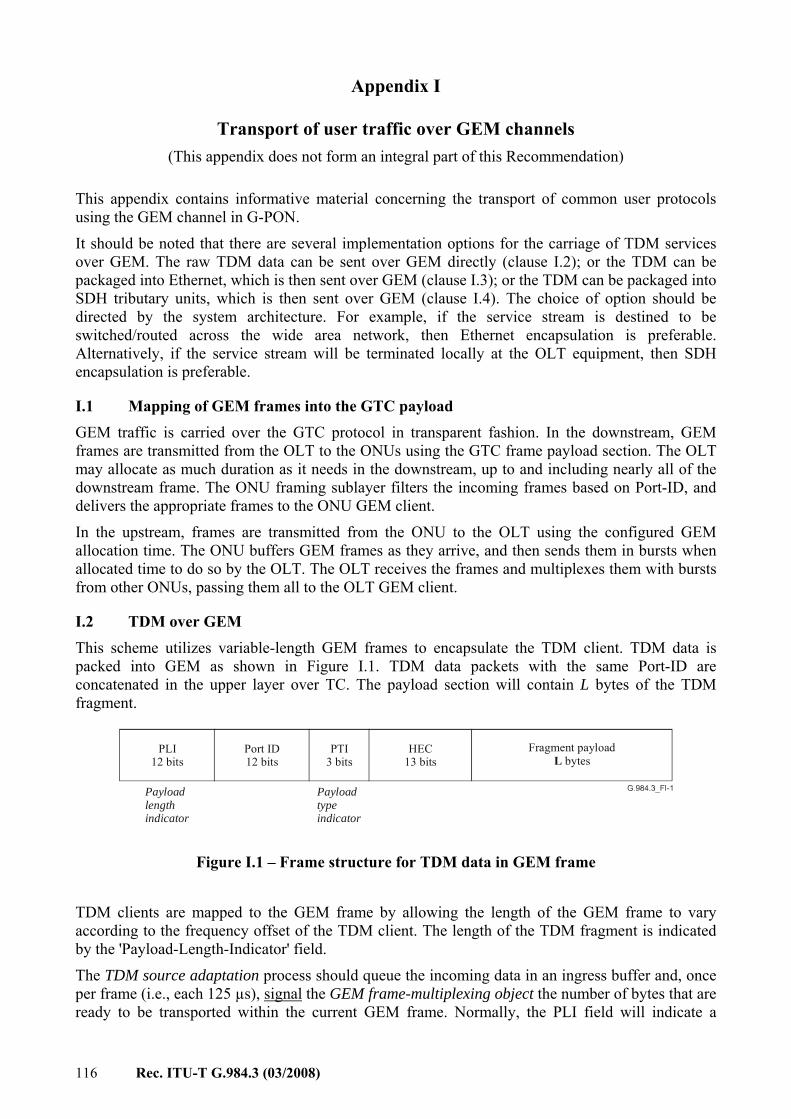
116 Rec. ITU-T G.984.3 (03/2008)
Appendix I
Transport of user traffic over GEM channels (This appendix does not form an integral part of this Recommendation)
This appendix contains informative material concerning the transport of common user protocols using the GEM channel in G-PON.
It should be noted that there are several implementation options for the carriage of TDM services over GEM. The raw TDM data can be sent over GEM directly (clause I.2); or the TDM can be packaged into Ethernet, which is then sent over GEM (clause I.3); or the TDM can be packaged into SDH tributary units, which is then sent over GEM (clause I.4). The choice of option should be directed by the system architecture. For example, if the service stream is destined to be switched/routed across the wide area network, then Ethernet encapsulation is preferable. Alternatively, if the service stream will be terminated locally at the OLT equipment, then SDH encapsulation is preferable.
I.1 Mapping of GEM frames into the GTC payload GEM traffic is carried over the GTC protocol in transparent fashion. In the downstream, GEM frames are transmitted from the OLT to the ONUs using the GTC frame payload section. The OLT may allocate as much duration as it needs in the downstream, up to and including nearly all of the downstream frame. The ONU framing sublayer filters the incoming frames based on Port-ID, and delivers the appropriate frames to the ONU GEM client.
In the upstream, frames are transmitted from the ONU to the OLT using the configured GEM allocation time. The ONU buffers GEM frames as they arrive, and then sends them in bursts when allocated time to do so by the OLT. The OLT receives the frames and multiplexes them with bursts from other ONUs, passing them all to the OLT GEM client.
I.2 TDM over GEM
This scheme utilizes variable-length GEM frames to encapsulate the TDM client. TDM data is packed into GEM as shown in Figure I.1. TDM data packets with the same Port-ID are concatenated in the upper layer over TC. The payload section will contain L bytes of the TDM fragment.
Payloadlengthindicator
PLI12 bits
Port ID12 bits
PTI
3 bits
HEC
13 bits
Fragment payload
bytesL
Payloadtypeindicator
Figure I.1 – Frame structure for TDM data in GEM frame
TDM clients are mapped to the GEM frame by allowing the length of the GEM frame to vary according to the frequency offset of the TDM client. The length of the TDM fragment is indicated by the 'Payload-Length-Indicator' field.
The TDM source adaptation process should queue the incoming data in an ingress buffer and, once per frame (i.e., each 125 µs), signal the GEM frame-multiplexing object the number of bytes that are ready to be transported within the current GEM frame. Normally, the PLI field will indicate a

Rec. ITU-T G.984.3 (03/2008) 117
constant number of bytes according to the nominal TDM rate. From time to time, one more or less byte will need to be transported. This would be reflected in the content of the PLI field.
If the output frequency is faster than the incoming signal frequency, the ingress buffer will start to empty. The buffer fill will eventually fall below the lower threshold. As a result, one less byte would be read from the ingress buffer, and the buffer fill would rise above the lower threshold. Conversely, if the output frequency is slower than the incoming signal frequency, the buffer will start to fill up. The buffer fill will eventually rise above the upper threshold. As a result, one more byte would be read from the ingress buffer, and the buffer fill would decrease below the upper threshold.
Figure I.2 depicts the concepts of mapping variable length TDM fragments into the payload section of a GEM frame.
Figure I.2 – TDM mapping over GEM
I.3 Ethernet over GEM The Ethernet frames are carried directly in the GEM frame payload. The preamble and SFD bytes are discarded prior to GEM encapsulation. Each Ethernet frame shall be mapped to a single GEM frame (as shown in Figure I.3) or multiple GEM frames, in which case the fragmentation rules of clause 8.3.3 apply. A GEM frame shall carry not more than one Ethernet frame.
PLI
Port-ID
PTI
CRC
GEM payload
Preamble
SFDDA
SALength/Type
MAC client data
FCS
7 1
6 6 2
4
5 bytes
Ethernet packet GEM frame
EOF
Inter packet gap12
1
Figure I.3 – Frame structure for Ethernet mapping into GEM frame

118 Rec. ITU-T G.984.3 (03/2008)
I.4 SDH over GEM [ITU-T G.707] defines tributary unit (TU) structures. These structures contain user data as well as several mechanisms to preserve and recover data timing that is independent from the transport system timing. GEM can provide the same type of synchronous transport as SDH, so it is possible to carry TU structures over GEM. This clause lays out the details of this method.
I.4.1 Review of SDH TU structures In SDH transmission structures, a TU includes a low level VC and a TU PTR. There are 4 types of TUs: TU-11, TU-12, TU-2, and TU-3. A TU-11 is used to carry a TDS1 service. A TU-12 is used to carry an E1 service. A TU-2 is used to carry a TDS2 service, and a TU-3 is used to carry a TDS3 or E3 service.
The TU-x structures are illustrated in Figures I.4 and I.5. Note that the bytes shown in the diagram are ordered starting at the upper left, going left to right, then on to the next line, and so forth.
Figure I.4 – The TU-11, TU-12 and TU-2 four-frame multifframe Structures

Rec. ITU-T G.984.3 (03/2008) 119
Figure I.5 – The TU-3 frame structure
The structure and function of the pointers in the V1, V2, V3 and V4 bytes in the TU-11, TU-12 and TU2; and in the H1, H2 and H3 bytes in a TU-3 frame, continue to operate exactly as described in [ITU-T G.707].
I.4.2 Transport of TU structures over GEM The structure about a TU frame mapped into a GEM frame is shown below:
Figure I.6 – GEM frame structure with TU frame data payload
Each TU connection is assigned its own GEM Port-ID. Each TU frame always has a fixed size. This size depends on the type of TU being carried. In addition, the GEM process receives a TU frame exactly once every transmission cycle. This cycle period is measured in the time-base of the G-PON system, which is a synchronous transport system with traceable timing. Hence, clock integrity can be maintained. It should be noted that GEM fragmentation is permitted; however, some implementations may attempt to coordinate the G-PON framing and SDH framing processes such that fragmentation is avoided.

120 Rec. ITU-T G.984.3 (03/2008)
The length and transmission period of TU-11/TU-12/TU-2/TU-3 capsulated in a GEM frame are shown below.
TU type Payload length in GEM [bytes] Transmission cycle
TU-11 4(3 × 9) = 108 TU-12 4(4 × 9) = 144 TU-2 4(12 × 9) = 432
500 μs
TU-3 86 × 9 = 774 125 μs
The payloads are assembled using the structures as shown in Figures I.4 to I.5.
The receiver side can identify the type of the carried TUs in two ways. Primarily, the Port-ID used would have a provisioned association with the TU that it is carrying. Secondarily, the length of the payload would give an additional check on the TU type, since the payload lengths are fixed for each TU type.
Note that while the GEM frame generation process is locked to the G-PON frame timing, there can still be delays in the frame transmission caused by low-level PON processes (e.g., ranging). For typical ranging procedures, two frames at a time are used for ranging. Therefore, the receiving process at the OLT must queue up sufficient TU data so that the client SDH processor can be served with its TU payloads synchronously.
I.5 IP over GEM
The IP packets are carried directly in the GEM frame payload. Each IP packet (or IP packet-fragment) shall be mapped to a single GEM frame (as shown in Figure I.7) or multiple GEM frames, in which case the fragmentation rules of clause 8.3.3 apply. A GEM frame shall carry not more than one IP packet (or IP packet-fragment).
PLIPort-ID
PTI
CRC
Source Addr.
Destination Addr.
V
GEMPayload
Id
CRC
IP Payload
TOS LengthHL
TTL Prot
Frag.OffFL
Figure I.7 – Frame structure for IP mapping into GEM frame

Rec. ITU-T G.984.3 (03/2008) 121
Appendix II
Survivability in GTC-based systems (This appendix does not form an integral part of this Recommendation)
Survivability in G-PON systems is modelled after that found in G.983.1-type PONs, as described in [ITU-T G.983.5]. Every aspect of [ITU-T G.983.5] operates the same in G-PON as in B-PON. The requirements, message exchange, configuration and switching methods are the same.

122 Rec. ITU-T G.984.3 (03/2008)
Appendix III
GEM header error control decoding (This appendix does not form an integral part of this Recommendation)
The structure of the GEM header is shown in Figure III.1.
Figure III.1 – The GEM header structure, showing detail of the 13-bit header error control field
The HEC in GEM is a double error correcting, triple error detecting code. It is composed of two parts. The first part is a truncated BCH(63, 12, 2) code. The generator polynomial for this code is x12 + x10 + x8 + x5 + x4 + x3 + 1. This code is applied to the payload of the header (which is 27 bits), so that the 39-bit result is divisible by the generator polynomial. The properties of this code are such that every single error and every double error has a unique 12-bit syndrome. Thus, all such errors can be corrected. Also, triple errors can produce syndromes that are either unique or match certain double error syndromes, but there is no triple error syndrome that matches a single error syndrome or zero. It is this last property that permits the use of a simple parity bit to detect and exclude triple errors.
The table of error syndromes for this code is given in the table below.
Error bit position
Syndrome (base 16)
Error bit position
Syndrome (base 16)
Error bit position
Syndrome (base 16)
1 977 14 2FF 27 539 2 E27 15 BE3 28 800 3 D8F 16 F6D 29 400 4 C5B 17 D2A 30 200 5 CB1 18 695 31 100 6 CC4 19 9D6 32 080 7 662 20 4EB 33 040 8 331 21 8E9 34 020 9 B04 22 EE8 35 010
10 582 23 774 36 008 11 2C1 24 3BA 37 004 12 BFC 25 1DD 38 002 13 5FE 26 A72 39 001

Rec. ITU-T G.984.3 (03/2008) 123
Because there are 39 unique single error syndromes, there are 741 unique double error syndromes. As there are 4095 possible syndromes in the 12-bit space, this leaves 3315 codes that are not used. These unused codes are considered 'illegal,' in that they can only result from three or more errors.
The second part of the GEM HEC is a simple parity bit. This parity bit is set so that the total number of ones in the header is an even number. This parity then indicates if an odd number of errors have occurred in the header. Note that the BCH code does not include the parity bit in its calculations, but the parity bit does include the BCH code in its calculation.
A few examples of valid GEM headers are given in the following table. Note that these headers are the as-computed value, and do not include the fixed pattern (0x0xB6AB31E055). These can be used to test implementations of the encoding and decoding processes.
528A739F79 B61925D883 BF2D33B47F 9727D4C430 7D3A32AA75 A257E5A295 7F2963C54B 7F0BF34736 7EF99F35F6 974CF521A3 86785F3E30 BB4A72F128
BEDB6545BA CE98AC73EF 7C6CA16F93 E617D9905C 0B2A61476B 95F1933472 BA487424EA 95F8B97926 BAB7C5FC86 BEBBF4A2E7 B9F1AFBA45 04E7E3A963 A6FB9FAEFF 7F4A25750A 9A696E9B88 86EA5F7CE3 CA47E19CFC BEDB7532FA DE1CDF6663 7E59A67E44 8A5CA75CE7 17986C90AB BA47F4EEFF BA9D39E439
The HEC can be decoded at the receiver by calculating the syndrome and the parity at the receiver, and then applying the following logic.
Case BCH syndrome result Parity result Header payload
error status Header payload action
1 No errors Even No errors Correct as is 2 No errors Odd No errors Correct as is 3 Single error Even One error Correctable single error 4 Single error Odd One error Correctable single error 5 Double error Even Two errors Correctable double error 6 Double error Odd 2 or more errors Uncorrectable 7 Illegal code Even 3 or more errors Uncorrectable 8 Illegal code Odd 3 or more errors Uncorrectable
Cases 1, 4 and 5 are such that the BCH and parity check agree in the number of errors. Cases 2 and 3 are situations where the parity bit must contain an error, so it is overridden by the BCH result. In case 6, a triple error must have occurred, since either a double payload error has happened and the parity is wrong, OR a triple payload error has occurred. In either event, the header is rejected. In cases 7 and 8, the BCH code has detected an illegal code, and the header is rejected.
The minimum number of errors required to cause an errored header to be accepted is 4. In the limit of many random errors, the probability of false acceptance is 10%.

124 Rec. ITU-T G.984.3 (03/2008)
Appendix IV
OLT activation procedures overview (This appendix does not form an integral part of this Recommendation)
This appendix describes how the activation process might be implemented in an OLT. This description is given for informative purposes in order to further clarify the interaction between the OLT and the ONU. The actual details of the OLT activation are left to the vendor.
The activation procedure described below gives an example of how the state machines of the OLT might be implemented. The specific details of the OLT implementation are left to the individual vendors.
The functions of the OLT during the activation procedure can be divided into the common part and the ONU-specific part(n). The common part performs a common function in one line interface and the ONU-specific part(n) performs functions pertaining to an individual ONU on a line interface. The states for both parts are described in detail below.
IV.1 Common part The common part deals with OLT functions that are common to one or more ONUs. Examples of this include acquisition of new ONU Serial numbers and the discovery of ONUs that return to service following LOS state.
IV.1.1 States of the OLT common part The states of the OLT Common part are defined as: a) Serial number acquisition standby state (OLT-COM1) OLT waits for a 'new' or 'missing' ONU indication, or for a periodic cycle time-out. b) Serial number acquisition state (OLT-COM2), When entering this state, the OLT starts the serial number acquisition cycle creating a quiet
window by withholding the bandwidth allocations for the active ONUs and transmitting a serial number request. The OLT checks for 'new' or 'missing' ONUs, and assigns an ONU-ID to each newly-discovered ONU.
When there are one or more newly discovered ONUs, the OLT activates an equalization delay measurement cycle for each discovered ONU. The OLT transitions to the equalization delay measurement standby state (OLT-COM3)
c) EQD measurement standby state (OLT-COM3). The OLT common part waits in this state while the various ONU-specific part(n)'s start
their equalization delay measurement cycles. As each equalization delay measurement cycle completes, it sends an indication to the OLT common part. When all equalization delay measurements are complete, the OLT Common part transitions to the serial number acquisition standby state (OLT-COM1).
IV.1.2 Common part state diagram
The OLT common part state diagram is shown in Figure IV.1.

Rec. ITU-T G.984.3 (03/2008) 125
OLT receives 'New' ONUsearch request received
from Ops system
Periodic Serial NumberAcquisition cycle time out
Missing ONU alarm
OLT receives DelayMeasurement Complete orDelay Measurement Failure
for all new ONUs
No Valid S/Ntransmission and
#-of-New-UNUs = 0
Serial Number Acquisitioncycle limit is reached
and #-of-New-ONUs > 0
No Valid Serial Numbertransmission
and #-of-New-ONUs > 0
Serial Number AcquistionStandby State(OLT-COM1)
The ONU waits for event
Serial Number AcquistionState (OLT-COM2)
OLT performs S/N measurement
RTD MeasurementStandby State (OLT-COM3)
OLT waits for ONU-specific partto complete RTD measurement
Serial Number Acquisitioncycle limit is reached
and #-of-New-ONUs =0
Figure IV.1 – OLT common part state diagram
IV.1.3 Functional transition table for the common part The following table describes the functional behaviour of the OLT common part with respect to state transitions. The first column in the table indicates the events that trigger an OLT action. The subsequent columns indicate the OLT action as a function of OLT state.
Serial number acquisition
standby state (OLT-COM1)
Serial number acquisition state (OLT-COM2)
EqD measurement standby state (OLT-COM3)
'New' ONU from OpS ⇒OLT-COM2 – –
Periodic serial number acquisition cycle time-out
⇒OLT-COM2 – –
'Missing' ONUs (LOS state) alarm
⇒OLT-COM2 – –
Received valid Serial_Number transmission for 'new' ONU
Extract SN; allocate free
ONU-ID
–
Received valid Serial_Number transmission for 'missing' ONU
Extract SN; re-assign the
ONU-ID
–
Received unexpected Serial_Number transmission
Deactivate ONU
No valid Serial_Number transmission received and #-of-New-ONUs = 0
⇒OLT-COM1

126 Rec. ITU-T G.984.3 (03/2008)
Serial number acquisition
standby state (OLT-COM1)
Serial number acquisition state (OLT-COM2)
EqD measurement standby state (OLT-COM3)
No valid Serial_Number transmission received and #-of-New-ONUs > 0
⇒OLT-COM3
Serial number acquisition cycle limit is reached and #-of-New-ONUs = 0
⇒OLT-COM1
Serial number acquisition cycle limit is reached and #-of-New-ONUs > 0
⇒OLT-COM3
OLT receives Delay measurement complete or delay measurement failure responses for all new ONUs
⇒OLT-COM1
IV.1.4 Events of the OLT common part The events of the OLT common part are defined as follows: a) 'New' ONU search request from OpS This event is generated when a new ONU is defined by the OpS. b) Periodic serial number acquisition cycle time-out When using the auto-discovery process, the OLT will start an SN cycle even if no ONUs
are missing. This event is generated when the time-out for this periodic operation has expired.
c) 'Missing' ONUs (loss-of-signal – LOS state) alarm This event is generated when the number of active ONUs (not in LOS) is less than the
number of installed ONUs, as defined by the OpS. d) Valid Serial_Number transmission for 'new' ONU This event is generated when a valid serial number response is received for a new ONU
during the SN acquisition cycle. A valid response is one with a valid CRC. The OLT responds by allocating a free ONU-ID and incrementing the #-of-new-ONUs parameter.
e) Valid Serial_Number transmission for 'missing' ONU This event is generated when a valid serial number response with correct ONU-ID is
received for a 'missing' ONU during the SN acquisition cycle. The OLT increments the #-of-new-ONUs parameter by one. While, technically, the missing ONU is not "new", it is necessary to increment this parameter in order to initiate the ranging process.
f) Received unexpected Serial_Number transmission This event is generated when an unexpected serial number is received during the SN
acquisition cycle. g) No valid Serial_Number transmission is received This event is generated when no Serial_Number transmission is received for
two Serial_Number cycles. h) Serial number acquisition cycle limit is reached This event is generated after the 10th serial number acquisition cycle.

Rec. ITU-T G.984.3 (03/2008) 127
i) Delay measurement complete This event is generated by the common part when it has received the delay measurement
complete(n) notification from all the ONU-specific part(n) that were discovered during the above serial number acquisition state. That is, the equalization delay measurements over all the ONUs has ended.
IV.2 ONU-specific part As its name implies, the ONU-specific part(n) deals specifically with the n-th ONU. The OLT will maintain up to 64 separate state machines, one for each ONU.
IV.2.1 States of the ONU-specific part The states of the ONU-specific-part(n) are defined as: a) Initial state (OLT-IDV1) The OLT is waiting for the ranging measurement start order, i.e., ONU(n) is in Initial state,
Standby state or Serial_Number state. b) Ranging measurement state (OLT-IDV2). When entering this state, the OLT starts the equalization delay measurement cycle. c) Operating state (OLT-IDV3) The ONU (n) is in Operation state. d) POPUP State (OLT-IDV4). The ONU (n) is in POPUP state.
IV.2.2 State diagram of the ONU-specific part The ONU-specific part(n) state diagram is shown in Figure IV.2.

128 Rec. ITU-T G.984.3 (03/2008)
Initial State (OLT-IDV1)OLT waits for Ranging start order
OLT detects LOS/LOFPOPUP TestSuccessful
OLT receives RangingMeasurement order (n)
from Common Part
Ranging Measurement State(OLT-IDV2)
OLT performs EqD measurements
Operating State(OLT-IDV3)
The ONU(n) is in Operation State
POPUP State(OLT-IDV4)
The ONU(n) is in POPUP State
OLT issues RangingMeasurement Complete (n)
to Common Part
OLT issues RangingMeasurement Failure
ot Common Part
POPUP TestFails 3 times
Figure IV.2 – ONU-specific part state diagram
IV.2.3 Functional behaviour table for the ONU-specific part The following table describes the functional behaviour in the ONU-specific part(n). The first column in the table indicates the event that generates an OLT response. The remaining columns indicate the resulting OLT actions as a function of OLT state.
Initial state (OLT-IDV1)
Ranging measurement state
(OLT-IDV2)
Operating state (OLT-IDV3)
POPUP state (OLT-IDV4)
Ranging measurement start order (n)
Notification of ranging measurement start (n). ⇒ OLT-IDV2
– – –
Ranging measurement complete (n)
– Send Ranging_time message three times. Notification of ranging measurement end (n). ⇒ OLT-IDV3
– –

Rec. ITU-T G.984.3 (03/2008) 129
Initial state (OLT-IDV1)
Ranging measurement state
(OLT-IDV2)
Operating state (OLT-IDV3)
POPUP state (OLT-IDV4)
Ranging measurement abnormal stop (n)
– Send Deactivate_ONU-ID message three times. Notification of ranging measurement end (n). ⇒ OLT-IDV1
– –
Detect of LOS(n), LOF(n)
– – Notification of LOS (n). ⇒ OLT-IDV4
IV.2.4 Events of the ONU-specific part The events are defined as follows: a) Ranging measurement start order (n) This event is generated when instruction is received from the common part. b) Ranging measurement complete (n) This event is issued by the ONU-specific part to the common part when the n-th
equalization delay measurement has been performed successfully. The n-th Ranging measurement has been performed successfully when the equalization
delay measurement has completed and the Ranging_time message containing the Equalization_Delay has been sent to ONU (n) three times. After issuing the ranging measurement complete (n), the OLT ONU-specific part transitions to the Operating state (OLT-IDV3).
c) Ranging measurement abnormal stop (n) This event is generated when the ranging measurement has failed. The ONU-specific part(n) sends a Deactivate_ONU-ID message to ONU(n) three times,
sends a notification of ranging measurement complete(n) to the OLT common part and the OLT transitions to the Initial state (OLT-IDV1).
d) Detect of LOS(n), LOF(n) This event causes the state to move to the POPUP state (OLT-IDV4).
IV.3 Automatic ONU Discovery Method
The activation procedure described above is applicable for several types of installation methods of ONUs.
The G-PON protocol relies on the unique serial number of the ONU for identification and provisioning purposes. Some operators will use an OpS that pre-provisions ONUs based on serial number. In this case, a directed activation method is used. In all other situations, the serial numbers of the ONUs are unknown initially and therefore must be discovered. G-PON allows for an automatic discovery method to accommodate this situation.
There are three triggers for initiating the activation of an ONU: – The network operator enables the activation process to start when it is known that a new
ONU has been connected. – The OLT automatically initiates the activation process, when one or more of the previously
working ONUs are 'missing', to see if those ONUs can return to service. The frequency of polling is programmable under instruction of the OpS.
130 Rec. ITU-T G.984.3 (03/2008)
– The OLT periodically initiates the activation process, testing to see if any new ONUs have been connected. The frequency of polling is programmable under instruction of the OpS.
IV.3.1 Type of activation process Different situations as described below are possible where the activation process may occur. There are three categories under which the activation process would occur.
IV.3.1.1 Cold PON, cold ONU This situation is characterized when no upstream traffic is running on the PON and the ONU has not yet received ONU-IDs from the OLT.
IV.3.1.2 Warm PON, cold ONU This situation is characterized by the addition of new ONU(s) that have not been previously ranged or by the addition of previously active ONU(s) having power restored and coming back to the PON while traffic is running on the PON.
IV.3.1.3 Warm PON, warm ONU This situation is characterized by a previously active ONU which remains powered on and connected to an active PON, but due to long alarm status, returned to Initial state (O1).
IV.4 POPUP process
The purpose of the POPUP state is to give ONUs, which detected LOS or LOF alarms, a certain period of time to recover and return to the Operation state without moving to the Initial state.
Since the ONU might be using a wrong EqD value (due to network protection operation or internal ONU error), the POPUP function will test the ONU before returning it to the Operation state.
Regarding the POPUP functioning, there are two pathways: • Transmission-Test – The OLT checks that the ONU transmission is received at the
expected location. • Ranging-Test – The OLT re-ranges the ONU.
Method 1 – Transmission-Test (using a directed POPUP message) 1) Following LOS/LOF, ONU enters the POPUP state. As long as the ONU is in the POPUP
state, no US transmission is allowed. All BW allocations are ignored by ONU. a) When entering the POPUP state, ONU activates the TO2 timer. b) Following time-out (TO2), ONU transits to the Initial state.
2) The OLT discovers that the ONU is in the POPUP state: it stops normal allocations to that the ONU, and sends the ONU a directed POPUP message.
3) When the ONU receives the POPUP message, the ONU transitions into the Operation state (this confirms that both sides know that the ONU has experienced an outage). a) When entering the Operation state, ONU stops the TO2 timer.
4) Before returning the ONU to full operation (regular allocations), the OLT can test the ONU by creating an appropriate quiet window and sending a short PLOAMu allocation (PLOAMu = '1', StartTime = X and StopTime = X + 12) to the ONU. a) ONU waits for its assigned EqD and responds to it with a PLOAMu transmission
based on the StartTime value (any PLOAMu is fine, and can be an empty PLOAM as well).

Rec. ITU-T G.984.3 (03/2008) 131
b) If the ONU responds back in the correct time, or the ONUs equalization delay can be adjusted based on the test transmission, OLT considers the ONU recovered and starts sending regular data allocations. Else, the OLT can deactivate the ONU.
Method 2 – Ranging-Test (using a broadcast POPUP message) 1) Following LOS/LOF, the ONU enters the POPUP state. As long as the ONU is in the
POPUP state, no US transmission is allowed. All BW allocations are ignored by the ONU. a) When entering the POPUP state, ONU activates the TO2 timer. b) Following time-out (TO2), ONU transits to the Initial state.
2) The OLT discovers that the ONU is in the POPUP state: it stops normal allocations to that ONU, and sends the ONU a broadcast POPUP message.
3) When the ONU receives the POPUP message, the ONU transitions into the Ranging state (this confirms that both sides know that the ONU has experienced an outage). a) When entering the Ranging state, the ONU stops the TO2 timer and activates the TO1
timer. 4) The OLT sends a ranging request (PLOAMu = "1", StartTime = X, and
StopTime = X + 12). 5) ONU waits for the pre-assigned delay and responds to the ranging request. 6) If the ONU responds, the OLT considers the ONU recovered and sends a ranging time
message. Else, the OLT can deactivate the ONU, or wait until the ONU reaches TO1 and moves back to the Standby state.
7) When the ONU gets the ranging time message, it transits to the Operation state. Else, following time-out (TO1), it transits to the Initial state.

132 Rec. ITU-T G.984.3 (03/2008)
Appendix V
Downstream line data pattern conditioning (This appendix does not form an integral part of this Recommendation)
This appendix describes two methods to control the downstream line pattern that are backward compatible and optional. The first improvement involves sending dummy packets from the OLT whose payload is designed to control the pattern of ones and zeroes on the line to reduce harmful optical effects. The second improvement is the application of AES to all unicast downstream traffic to prevent a user from intentionally disrupting the PON.
V.1 Idle pattern control The basic concept of this technique is for the OLT to send dummy packets during periods of low system utilization. The dummy packets have the characteristics that they have a Port-ID that is not used by any ONU or service, and that their payload is devised such that a desired pattern is impressed on the downstream line signal.
The size of the dummy packets is an arbitrary choice of implementation However, to make the system efficient in both data transport and pattern control, it is advised that the size of the dummy payload range from 48 to 64 bytes. This will make the fraction of controlled line signal greater than 90% in the absence of real data, and it will occupy the line for no longer than 0.23 microseconds.
The Port-ID used for the dummy packets or cells is also an arbitrary choice of implementation. Because the OLT has complete control over the Port-ID address space, it is entirely up to the OLT to choose the 'dummy address'.
There are two implementation methods described in this appendix for determining the contents of the payload for these dummy packets: 1) choose payload that is independent of the scrambler phase, and 2) choose payload that is dependent on the scrambler phase.
V.1.1 Scrambler phase-independent payload This method chooses the dummy packet payload without knowledge of the scrambler phase. In this method, the payload can either be fixed or random. If the payload is fixed, then the fixed payload should be chosen such that it minimizes the peak value of any discrete spectral lines produced after scrambling. There are at least two methods for generating random payload: 1) using a long free-running PN generator (e.g., 243–1), or 2) filling the payload with AES encrypted data.
Figure V.1 illustrates the operation of this idle pattern control scheme. The blue curve shows the spectrum resulting from the exclusive-OR of the repeating 5-byte pattern 0xB6AB31E055 (the GEM idle header) with the 127-bit scrambler sequence with a bit rate of 2.488 Gbit/s. The green curve shows the spectrum resulting from the exclusive-OR of the repeating 53-byte pattern: 0xB5AB 31EA F3C5 EEC0 5212 677E E7E0 CB22 1A12 99E0 F997 26A8 4111 ACB3 86B8 B96E 3724 6C7B 0B70 0505 95CE 5452 8103 BF00 7905 98C3 DA with the 127-bit scrambler sequence with a bit rate of 2.488 Gbit/s, resulting in a 10 dB reduction in the peak relative to the GEM idle header. The red curve shows the spectrum resulting from the exclusive-OR of a repeating 53-byte random payload with the 127-bit scrambler sequence with a bit rate of 2.488 Gbit/s, resulting in a 13.7 dB reduction in the peak relative to the GEM idle header.
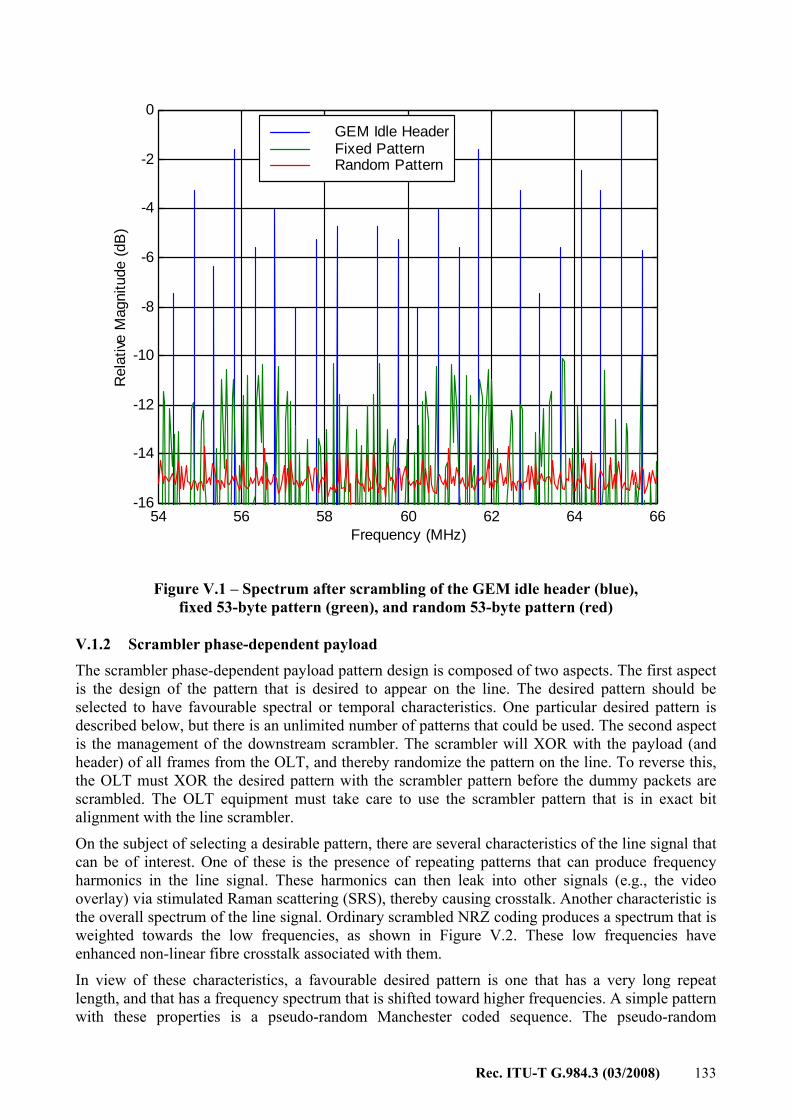
Rec. ITU-T G.984.3 (03/2008) 133
54 56 58 60 62 64 66-16
-14
-12
-10
-8
-6
-4
-2
0
Frequency (MHz)
Rel
ative
Mag
nitu
de (d
B)
GEM Idle HeaderFixed Pattern Random Pattern
Figure V.1 – Spectrum after scrambling of the GEM idle header (blue), fixed 53-byte pattern (green), and random 53-byte pattern (red)
V.1.2 Scrambler phase-dependent payload The scrambler phase-dependent payload pattern design is composed of two aspects. The first aspect is the design of the pattern that is desired to appear on the line. The desired pattern should be selected to have favourable spectral or temporal characteristics. One particular desired pattern is described below, but there is an unlimited number of patterns that could be used. The second aspect is the management of the downstream scrambler. The scrambler will XOR with the payload (and header) of all frames from the OLT, and thereby randomize the pattern on the line. To reverse this, the OLT must XOR the desired pattern with the scrambler pattern before the dummy packets are scrambled. The OLT equipment must take care to use the scrambler pattern that is in exact bit alignment with the line scrambler.
On the subject of selecting a desirable pattern, there are several characteristics of the line signal that can be of interest. One of these is the presence of repeating patterns that can produce frequency harmonics in the line signal. These harmonics can then leak into other signals (e.g., the video overlay) via stimulated Raman scattering (SRS), thereby causing crosstalk. Another characteristic is the overall spectrum of the line signal. Ordinary scrambled NRZ coding produces a spectrum that is weighted towards the low frequencies, as shown in Figure V.2. These low frequencies have enhanced non-linear fibre crosstalk associated with them.
In view of these characteristics, a favourable desired pattern is one that has a very long repeat length, and that has a frequency spectrum that is shifted toward higher frequencies. A simple pattern with these properties is a pseudo-random Manchester coded sequence. The pseudo-random

134 Rec. ITU-T G.984.3 (03/2008)
generator can be selected to have a primitive high-order polynomial (e.g., 243-1), and is configured to operate at half the bit rate of the downstream signal. Then, each pseudo-random digit is encoded as a Manchester code symbol (01 or 10). The resulting pattern will have a spectrum as shown in Figure V.2, illustrated for the case of 2.488 Gbit/s downstream transmission.
One must keep in mind that the idle pattern control is only effective for the fraction of time that the downstream G-PON system is idle. To illustrate this, let's suppose that the system is operating at approximately 25% occupancy, and that the dummy packet payloads are created to be 48 bytes long. In this case, the desired pattern appears on the line approximately 67% of the time. Therefore, the spectrum of the line signal will be the weighted average of the scrambled and Manchester coded spectra. The average reduction in spectral intensity is then as shown in Figure V.2. In the important 50~100 MHz region, the reduction is around 4 dB in this example. This would produce a 3 dB improvement in Raman impairments for overlay signals on the PON. It should be noted that higher downstream utilization will produce less improvement, and vice-versa.
Figure V.2 – Spectra of ordinary scrambled pattern, Manchester-coded pattern, the average code, and the average reduction in spectral intensity
V.2 Intentional PON disruption Because the scrambler sequence in this Recommendation is relatively short (127 bits), it is possible that a user could intentionally disrupt the PON by downloading packets filled with the scrambler sequence. This could lead to excessive consecutive identical digits being transmitted, which will likely result in the ONU receivers losing synchronization. To prevent this possibility, it is recommended that AES be activated on all point-to-point connections on the PON.
0.00
0.20
0.40
0.60
0.80
1.00
1.20
0 622 1244 1866 2488 Frequency (MHz)
Spec
tral
Inte
nsity
-6.0
-4.0
-2.0
0.0
2.0
4.0
6.0
Ram
an R
educ
tion
(dB
)
Scrambled Code Manchester Code
Averaged Code
Averaged Reduction

Rec. ITU-T G.984.3 (03/2008) 135
Bibliography
[b-ITU-T G.652] Recommendation ITU-T G.652 (2005), Characteristics of a single-mode optical fibre and cable.
[b-ITU-T G.671] Recommendation ITU-T G.671 (2005), Transmission characteristics of optical components and subsystems.
[b-ITU-T G.709] Recommendation ITU-T G.709/Y.1331 (2003), Interfaces for the Optical Transport Network (OTN).
[b-ITU-T G.783] Recommendation ITU-T G.783 (2006), Characteristics of synchronous digital hierarchy (SDH) equipment functional blocks.
[b-ITU-T G.841] Recommendation ITU-T G.841 (1998), Types and characteristics of SDH network protection architectures.
[b-ITU-T G.975] Recommendation ITU-T G.975 (2000), Forward error correction for submarine systems.
[b-ITU-T G.984.4] Recommendation ITU-T G.984.4 (2008), Gigabit-capable passive optical networks (G-PON): ONT management and control interface specification.
[b-ITU-T I.610] Recommendation ITU-T I.610 (1999), B-ISDN operation and maintenance principles and functions.
[b-ITU-T J.81] Recommendation ITU-T J.81 (1993), Transmission of component-coded digital television signals for contribution-quality applications at the third hierarchical level of ITU-T Recommendation G.702.
[b-RFC 2597] IETF RFC 2597 (1999), Assured Forwarding PHB Group. <http://www.ietf.org/rfc/rfc2597.txt?number=2597>
[b-RFC 2698] IETF RFC 2698 (1999), A Two Rate Three Color Marker. <http://www.ietf.org/rfc/rfc2698.txt?number=2698>
[b-RFC 4115] IETF RFC 4115 (2005), A Differentiated Service Two-Rate, Three-Color Marker with Efficient Handling of in-Profile Traffic. <http://www.ietf.org/rfc/rfc4115.txt?number=4115>
[b-ANSI T1.220] ATIS-0322000.2005, Representation of the Communications Industry Manufacturers, Suppliers, and Related Service Companies for Information Exchange (Revision of T1.220-2000). <http://webstore.ansi.org/RecordDetail.aspx?sku=ATIS-0322000.2005>


Printed in Switzerland Geneva, 2009
SERIES OF ITU-T RECOMMENDATIONS
Series A Organization of the work of ITU-T
Series D General tariff principles
Series E Overall network operation, telephone service, service operation and human factors
Series F Non-telephone telecommunication services
Series G Transmission systems and media, digital systems and networks
Series H Audiovisual and multimedia systems
Series I Integrated services digital network
Series J Cable networks and transmission of television, sound programme and other multimedia signals
Series K Protection against interference
Series L Construction, installation and protection of cables and other elements of outside plant
Series M Telecommunication management, including TMN and network maintenance
Series N Maintenance: international sound programme and television transmission circuits
Series O Specifications of measuring equipment
Series P Telephone transmission quality, telephone installations, local line networks
Series Q Switching and signalling
Series R Telegraph transmission
Series S Telegraph services terminal equipment
Series T Terminals for telematic services
Series U Telegraph switching
Series V Data communication over the telephone network
Series X Data networks, open system communications and security
Series Y Global information infrastructure, Internet protocol aspects and next-generation networks
Series Z Languages and general software aspects for telecommunication systems