Embed Size (px)
Citation preview
INTERNATIONAL TELECOMMUNICATION UNION
ITU-T Q.1214 TELECOMMUNICATION (03/93) STANDARDIZATION SECTOR OF ITU
GENERAL RECOMMENDATIONS ON TELEPHONE SWITCHING AND SIGNALLING INTELLIGENT NETWORK
DISTRIBUTED FUNCTIONAL PLANE FOR INTELLIGENT NETWORK CS-1 ITU-T Recommendation Q.1214
(Previously �CCITT Recommendation�)
FOREWORD
The ITU Telecommunication Standardization Sector (ITU-T) is a permanent organ of the International Telecom-munication Union. The ITU-T is responsible for studying technical, operating and tariff questions and issuing Recommendations on them with a view to standardizing telecommunications on a worldwide basis.
The World Telecommunication Standardization Conference (WTSC), which meets every four years, established the topics for study by the ITU-T Study Groups which, in their turn, produce Recommendations on these topics.
ITU-T Recommendation Q.1214 was prepared by the ITU-T Study Group XI (1988-1993) and was approved by the WTSC (Helsinki, March 1-12, 1993).
___________________
NOTES
1 As a consequence of a reform process within the International Telecommunication Union (ITU), the CCITT ceased to exist as of 28 February 1993. In its place, the ITU Telecommunication Standardization Sector (ITU-T) was created as of 1 March 1993. Similarly, in this reform process, the CCIR and the IFRB have been replaced by the Radiocommunication Sector.
In order not to delay publication of this Recommendation, no change has been made in the text to references containing the acronyms �CCITT, CCIR or IFRB� or their associated entities such as Plenary Assembly, Secretariat, etc. Future editions of this Recommendation will contain the proper terminology related to the new ITU structure.
2 In this Recommendation, the expression �Administration� is used for conciseness to indicate both a telecommunication administration and a recognized operating agency.
ITU 1993
All rights reserved. No part of this publication may be reproduced or utilized in any form or by any means, electronic or mechanical, including photocopying and microfilm, without permission in writing from the ITU.
Recommendation Q.1214 (03/93) i
CONTENTS Recommendation Q.1214 (03/93)
Page 1 General ........................................................................................................................................................... 1 2 Scope of IN distributed functional plane for capability Set 1 ........................................................................ 1
2.1 End user access ................................................................................................................................. 1 2.2 Service invocation and control ......................................................................................................... 1 2.3 End user interaction .......................................................................................................................... 2 2.4 Service management ......................................................................................................................... 2
3 Distributed functional model for CS-1........................................................................................................... 2 3.1 Explanation of diagram..................................................................................................................... 2 3.2 IN functional model .......................................................................................................................... 3 3.3 Definition of functional entities related to IN service execution ...................................................... 4
4 Functional entity call/service logic processing models .................................................................................. 5 4.1 Overview .......................................................................................................................................... 5 4.2 SSF/CCF model ................................................................................................................................ 5 4.3 Specialized resource function (SRF) model ..................................................................................... 43 4.4 Service control function (SCF) model .............................................................................................. 45 4.5 Service data function (SDF) model .................................................................................................. 50
5 Stage 2 descriptions of service independent building blocks (SIBs) ............................................................. 52 5.1 Introduction ...................................................................................................................................... 52 5.2 SIB stage 2 descriptions.................................................................................................................... 55 5.3 Basic call process SIB....................................................................................................................... 128 5.4 Stage 2 description of other distributed functionality....................................................................... 135 5.5 Mapping of the global functional plane to the distributed functional plane ..................................... 140
6 Relationships between FEs............................................................................................................................. 149 6.1 General.............................................................................................................................................. 149 6.2 Relationships..................................................................................................................................... 149 6.3 Information flows between FEs........................................................................................................ 151 6.4 SCF-SSF relationship ....................................................................................................................... 151 6.5 SCF-SRF relationship ....................................................................................................................... 191 6.6 SCF-SDF relationship....................................................................................................................... 195 6.7 Summary of information flows and related SIBs.............................................................................. 197
Annex A � Communication between call segments ............................................................................................... 204 Annex B � SSF/CCF relationship scenarios........................................................................................................... 207 Appendix I � Aspects of the distributed functional plane Identified as �for further study� (FFS) Appendix I � Relative to CS-1 ............................................................................................................................... 214
I.1 General.............................................................................................................................................. 214 I.2 Information flows (IFs)..................................................................................................................... 214 I.3 Information elements (IE)................................................................................................................. 218 I.4 Chart � IFs, IEs ................................................................................................................................. 220 I.5 BCP SIB Stage 2............................................................................................................................... 221
ii Recommendation Q.1214 (03/93)
SUMMARY
This Recommendation defines the intelligent network (IN) distributed functional plane (DFP) architecture for IN capability set 1 (CS-1). It does define the IN DFP for CS-1 based on the general framework for IN DFP studies provided in Recommendation Q.1204, consistent with the scope of CS-1 defined in Recommendation Q.1211.
This Recommendation provides � the IN DFP architecture for CS-1, in terms of a subset of the general IN DFP architecture encompassing
only the functional entities related to IN service execution; � static and dynamic models of the functional entities related to IN service execution (including service
switching/call control, service control, specialized resource, and service data functions), to define how IN service control interacts with basic call processing and to understand the nature of the functional entity relationships required for CS-1;
� SIB stage 2 descriptions to identify information flows and functional entity actions for CS-1; – detailed information flow descriptions, including information elements and functional descriptions, as the
basis for specifying IN protocols; � a starting point for the study of call party handling capabilities beyond two-party call setup and clearing.
This Recommendation forms a useful basis for gaining implementation experience with the IN DFP. As with any project of this size and complexity, it can be anticipated that there may be difficulties in interworking the various implementations of physical elements based on IN CS-1 DFP functionality. To achieve the IN objective of a multi-vendor environment, this Recommendation may go through some future revision in the light of implementation experience.
Within the Q.121x-Series Recommendations, this Recommendation describes the distribution of global functional plane functionality defined in Recommendation Q.1213 (i.e. service independent building blocks [SIBs] for CS-1) in a service and vendor/implementation independent manner, as constrained by the capabilities of the embedded base of evolvable network technology. This provides the flexibility to allocate distributed functionality into multiple physical network configurations, as described in Recommendation Q.1215, and to evolve IN from CS-1 to some future CS-N. It also provides a framework from which IN protocols are specified for CS-1, as described in Recommendation Q.1218.
Recommendation Q.1214 (03/93) 1
Recommendation Q.1214 Recommendation Q.1214 (03/93)
DISTRIBUTED FUNCTIONAL PLANE FOR INTELLIGENT NETWORK CS-1 (Helsinki, 1993)
1 General General aspects of the DFP are contained in 1/Q.1204.
2 Scope of IN distributed functional plane for capability Set 1 The scope of the IN distributed functional plane (DFP) architecture for IN capability set 1 (CS-1) is driven by the service requirements of desired CS-1 services, and constrained by the capabilities of the embedded base of evolvable network technology. The scope of functionality required to support desired CS-1 services includes functionality to provide:
� end user access to call/service processing; � service invocation and control; � end user interaction with service control; � and service management.
The scope of each of these aspects is addressed below.
2.1 End user access
End user access to call/service processing for CS-1 will be provided via the following access arrangements:1) � analogue line interfaces; � ISDN BRI and PRI; and � traditional trunk and SS No. 7 interfaces.
2.2 Service invocation and control
Call/service processing for CS-1 builds upon the current call processing infrastructure of existing digital exchanges. It does so by using a generic model of existing call control functionality to process basic two-party calls, then adding service switching functionality to invoke and manage IN service logic. Once invoked, IN service logic is executed under the control of service control functionality, in conjunction with service data functionality. With this distributed approach to call/service processing, the existing call control functionality retains ultimate responsibility for the integrity of calls, as well as for the control of call processing resources. The following call/service processing constraints apply for CS-1:
a) Call control and service switching functionality are tightly coupled, thus the relationship between SSF and CCF is not standardized in CS-1.
b) A call is either between two or more end users that are external to the network and addressable via a directory number or combination of directory number and bearer capability, or a call is between one or more end users and the network itself.
c) A call may be initiated by an end user, or by an SCF within the network on behalf of an end user. To supplement a call, IN service logic may either be invoked by an end user served by an IN exchange, or by the network on behalf of an end user.
_______________ 1) This does not preclude the use of these interfaces to support access from private or mobile networks.
2 Recommendation Q.1214 (03/93)
d) A call may span multiple exchanges. As such, each exchange only controls the portion of the call in that exchange � call processing is functionally separated between exchanges. IN service logic invoked on IN exchanges in such an inter-exchange call are managed independently by each IN exchange.
e) Existing exchanges can be viewed as having two functionally separate sets of call processing logic that coordinate call processing activities to create and maintain a basic two-party call. This functional separation is provided between the originating portion of the call and the terminating portion of the call. This functional separation should be maintained in an IN exchange to allow IN service logic invoked on the originating portion of the call (i.e. on behalf of the calling party) to be managed independently of IN service logic invoked on the terminating portion of the call (i.e. on behalf of the called party).
f) It is desirable to allow multiple IN-supported service logic instances to be simultaneously active for a given end user. It is also recognized that non-IN service logic will continue to exist in the network. As such, service feature logic instances mechanisms for CS-1 should:
� determine which service logic to invoke for a given service request. This mechanism should select the appropriate IN-supported service logic or non-IN-supported service logic, and block the invocation of any other service logic for that particular service request;
� limit simultaneously active IN- and non-IN-supported service logic instances;
� ensure that simultaneously active IN-supported service logic instances adhere to the single-ended, single point of control restriction on CS-1 service processing.
g) The distributed approach and added complexity of call/service processing for CS-1 requires mechanisms for fault detection and recovery, allowing graceful termination of calls and appropriate treatments for end users.
2.3 End user interaction
End user interaction with the network to send and receive information is provided by service switching and call control resources, augmented by specialized resources. These specialized resources are controlled by service control functionality, and are connected to end users via call control and service switching functionality.
2.4 Service management
Service management functionality is used to provision and manage the service control functionality, service data functionality, and specialized resource functionality in the network, outside of the context of call/service processing. Standardized interfaces for this functionality are outside the scope of CS-1. However, the ability of a service subscriber to interact directly with subscriber-specific service management information will not be excluded or constrained for CS-1.
3 Distributed functional model for CS-1
3.1 Explanation of diagram
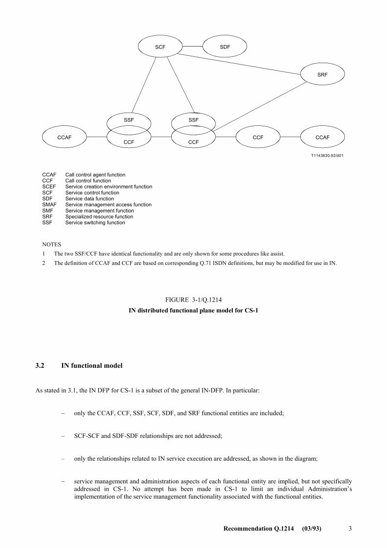
Figure 3-1 identifies the IN DFP model for CS-1. This diagram depicts the functional entities and relationships applicable to CS-1. This diagram is a subset of the generic IN DFP model described in 2/Q.1204. A general explanation of functional entities, relationships, and the diagram are contained in 2.1/Q.1204.
Recommendation Q.1214 (03/93) 3
T1143830-92/d01
SCF SDF
SRF
CCAF CCF CCAF
SSF
CCF
SSF
CCF
CCAFCCFSCEFSCFSDFSMAFSMFSRFSSF
Call control agent functionCall control functionService creation environment functionService control functionService data functionService management access functionService management functionSpecialized resource functionService switching function
NOTES1 The two SSF/CCF have identical functionality and are only shown for some procedures like assist.2 The definition of CCAF and CCF are based on corresponding Q.71 ISDN definitions, but may be modified for use in IN.
FIGURE 3-1/Q.1214IN distributed functional plane model for CS-1
FIGURE 3-1/Q.1214...[D01] = 15 CM
3.2 IN functional model
As stated in 3.1, the IN DFP for CS-1 is a subset of the general IN-DFP. In particular:
� only the CCAF, CCF, SSF, SCF, SDF, and SRF functional entities are included;
� SCF-SCF and SDF-SDF relationships are not addressed;
� only the relationships related to IN service execution are addressed, as shown in the diagram;
� service management and administration aspects of each functional entity are implied, but not specifically addressed in CS-1. No attempt has been made in CS-1 to limit an individual Administration�s implementation of the service management functionality associated with the functional entities.
4 Recommendation Q.1214 (03/93)
3.3 Definition of functional entities related to IN service execution
The CCA function (CCAF): The CCAF is the call control agent (CCA) function that provides access for users. It is the interface between user and network call control functions. It
a) provides for user access, interacting with the user to establish, maintain, modify and release, as required, a call or instance of service;
b) accesses the service-providing capabilities of the call control function (CCF), using service requests (e.g. setup, transfer, hold, etc.) for the establishment, manipulation and release of a call or instance of service;
c) receives indications relating to the call or service from the CCF and relays them to the user as required;
d) maintains call/service state information as perceived by this functional entity.
The CC function (CCF): The CCF is the call control (CC) function in the network that provides call/service processing and control. It
a) establishes, manipulates and releases call/connection as �requested� by the CCAF;
b) provides the capability to associate and relate CCAF functional entities that are involved in a particular call and/or connection instance (that may be due to SSF requests);
c) manages the relationship between CCAF functional entities involved in a call (e.g. supervises the overall perspective of the call and/or connection instance);
d) provides trigger mechanisms to access IN functionality (e.g. passes events to the SSF).
The SS function (SSF): The SSF is the service switching (SS) function, which, associated with the CCF, provides the set of functions required for interaction between the CCF and a service control function (SCF). It
a) extends the logic of the CCF to include recognition of service control triggers and to interact with the SCF;
b) manages signalling between the CCF and the SCF;
c) modifies call/connection processing functions (in the CCF) as required to process requests for IN provided service usage under the control of the SCF.
The SC function (SCF): The SCF is a function that commands call control functions in the processing of IN provided and/or custom service requests. The SCF may interact with other functional entities to access additional logic or to obtain information (service or user data) required to process a call/service logic instance. It
a) interfaces and interacts with service switching function/call control function, specialized resource function (SRF) and service data function (SDF) functional entities;
b) contains the logic and processing capability required to handle IN provided service attempts.
The SD function (SDF): The SDF contains customer and network data for real time access by the SCF in the execution of an IN provided service. It interfaces and interacts with SCFs as required.
NOTE � The SDF contains data relating directly to the provision or operation of IN provided services. Thus it does not necessarily encompass data provided by third party such as credit information, but may provide access to these data.
Recommendation Q.1214 (03/93) 5
The SR function (SRF): The SRF provides the specialized resources required for the execution of IN provided services (e.g., digit receivers, announcements, conference bridges, etc). It
a) interfaces and interacts with SCF and SSF (and with the CCF);
b) may contain the logic and processing capability to receive/send and convert information received from users;
c) may contain functionality similar to the CCF to manage bearer connections to the specialized resources.
4 Functional entity call/service logic processing models
4.1 Overview
IN call/service logic processing encompasses call and connection processing in the SSF/CCF, service logic execution in the SCF, and the use of supporting resources and data in the SRF and SDF, respectively. This subclause describes this IN call/service logic processing in terms of call modelling and modelling of service logic processing.
� Call modelling provides a high-level service and vendor/implementation independent abstraction of IN call and connection processing in the SSF and CCF. This abstraction provides an observable view of SSF/CCF activities and resources to the SCF, enabling the SCF to interact with the SSF in the course of executing service logic.
� The modelling of service logic processing provides an abstraction of SCF activities and resources needed to support this service logic execution, as well as an abstraction of SRF and SDF activities and resources accessible to the SCF.
Since this modelling only provides an observable (i.e. external) view of SSF/CCF, SCF, SRF, and SDF activities and resources, this modelling does not imply an obligation to vendors to implement functional entities into products as a one-to-one mapping of functional entity model components.
The modelling in this subclause is based on the modelling objectives, assumptions, and architecture described in 3/Q.1204, and makes use of the tools identified in its annexes, as applicable to CS-1.
4.2 SSF/CCF model
4.2.1 General
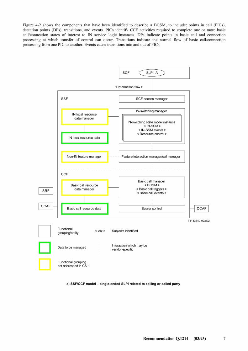
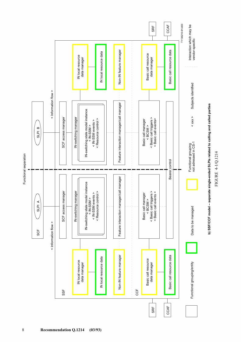
A model of the SSF/CCF is shown in Figures 4-1a) and 4-1b). Figure 4-1a) shows the SSF/CCF model for a single-ended service logic instance related to a calling or called party. Figure 4-1b) shows the SSF/CCF model for separate single-ended service logic instances related to the calling and called parties on the same call. The purpose of this model is to provide a framework for call modelling subjects with respect to the SSF/CCF.
The aspects of the SSF/CCF model briefly described below include the basic call manager (BCM), the IN-switching manager (IN-SM), the feature interactions manager (FIM)/call manager (CM), the relationship of the BCM to the IN-SM, the relationship of the BCM and IN-SM to the FIM/CM, and the functional separation provided in the SSF/CCF. Additional detail is provided in subsequent subclauses.
a) BCM � The entity in the CCF that provides basic call and connection control to establish communication paths for users and interconnects such communication paths, that detects basic call and connection control events that can lead to the invocation of IN service logic instances or should be reported to active IN service logic instances, and that manages CCF resources required to support basic call and connection control. The BCM interacts with the FIM/CM as described in the FIM/CM description below.
b) IN-SM � The entity in the SSF that interacts with the SCF in the course of providing IN service features to users. It provides the SCF with an observable view of SSF/CCF call/connection processing activities, and provides the SCF with access to SSF/CCF capabilities and resources. It also detects IN call/connection processing events that should be reported to active IN service logic instances, and
6 Recommendation Q.1214 (03/93)
manages SSF resources required to support IN service logic instances. The IN-SM interacts with the FIM/CM as described below.
c) FIM/CM � The entity in the SSF that provides mechanisms to support multiple concurrent instances of IN service logic instances and non-IN service logic instances on a single call. In particular, the FIM/CM can prevent multiple instances of IN and non-IN service logic instances from being invoked. The ability of the FIM/CM to arbitrate between multiple instances of IN and non-IN service logic instances is for further study. The FIM/CM integrates these interactions mechanisms with the BCM and IN-FM to provide the SSF with a unified view of call/service processing internal to the SSF for a single call.
d) BCM relationship to IN-SM � The relationship that encompasses the interaction between the BCM and the IN-SM, through the FIM/CM. The information flow related to this interaction is not externally visible and is not standardized for CS-1. However, an understanding of this subject is required to identify how basic call and connection processing and IN call/connection processing may interact.
e) BCM and IN-SM relationships to FIM/CM � The relationships that encompass the interaction between the BCM and the FIM/CM, and the IN-SM and the FIM/CM. The information flows related to these interactions are not externally visible and are not standardized for CS-1. However, an understanding of this subject is required in order to unify the BCM, IN-SM and FIM/CM.
f) Functional separation in the SSF/CCF [Figure 4-1b)] � The functional separation of processes and resources in the SSF/CCF that provides a means of handling service logic instance interactions for CS-1. This functional separation serves to isolate single-ended service logic instances related to the calling party from single-ended service logic instances related to the called party for the same call. Within the scope of CS-1, there is no functionality in the SSF for handling service feature interactions between the separate SSF calling party processes and SSF called party processes.
Other aspects shown in Figure 4-1 are not addressed for CS-1, but are assumed to exist.
4.2.2 Basic call manager (BCM)
A brief description of the BCM is provided in 4.2.1. The particular BCM subjects addressed below include the basic call state model (BCSM), basic call and connection events that can lead to the invocation of IN service logic instances, and basic call and connection events that should be reported to active IN service logic instances. A high-level description of these subjects is provided below.
4.2.2.1 BCSM
The BCSM is a high-level finite state machine description of CCF activities required to establish and maintain communication paths for users. As such, it identifies a set of basic call and connection activities in a CCF and shows how these activities are joined together to process a basic call and connection (i.e. establish and maintain a communication path for a user).
Many aspects of the BCSM are not externally visible to IN service logic instances. However, aspects of the BCSM that are reflected upward to the IN-FM and FIM/CM are visible to IN service logic instances. Only these aspects of the BCSM will be the subject of standardization. As such, the BCSM is primarily an explanatory tool for providing a representation of CCF activities that can be analysed to determine which aspects of the BCSM will be visible to IN service logic instances, if any, and what level of abstraction and granularity is appropriate for this visibility.
The BCSM identifies points in basic call and connection processing when IN service logic instances are permitted to interact with basic call and connection control capabilities. In particular, it provides a framework for describing basic call and connection events that can lead to the invocation of IN service logic instances or should be reported to active IN service logic instances, for describing those points in call and connection processing at which these events are detected, and for describing those points in call and connection processing when the transfer of control can occur.
Recommendation Q.1214 (03/93) 7
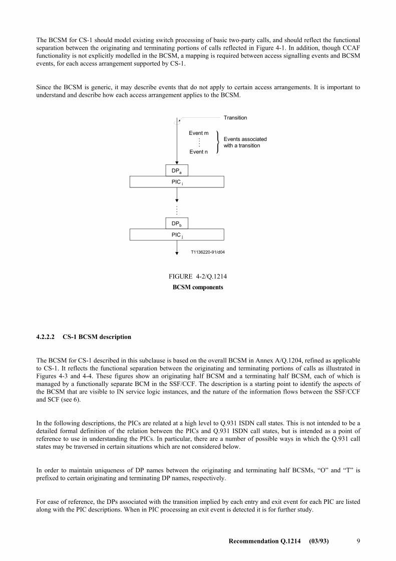
Figure 4-2 shows the components that have been identified to describe a BCSM, to include: points in call (PICs), detection points (DPs), transitions, and events. PICs identify CCF activities required to complete one or more basic call/connection states of interest to IN service logic instances. DPs indicate points in basic call and connection processing at which transfer of control can occur. Transitions indicate the normal flow of basic call/connection processing from one PIC to another. Events cause transitions into and out of PICs.
T1143840-92/d02
SLPI ASCF
SCF access manager
SRF
CCAFCCAF
IN local resourcedata manager
IN local resource data
Non-IN feature manager
Basic call resource data manager
Basic call resource data
Feature interaction manager/call manager
Bearer control
IN-switching manager
IN-switching state model instance< IN-SSM >
< IN-SSM events >< Resource control >
Basic call manager< BCSM >
< Basic call triggers >< Basic call events >
< Information flow >
SSF
CCF
Functionalgrouping/entity
Data to be managed
Functional groupingnot addressed in CS-1
< xxx > Subjects identified
Interaction which may bevendor-specific
a) SSF/CCF model � single-ended SLPI related to calling or called party
FIGURE 4-1a)/Q.1214...[D02] = 18.5 CM
8 Recommendation Q.1214 (03/93)
T113
6210
-91/
d03
Func
tiona
l sep
arat
ion
SC
F
SS
F
CC
F
SLPI
AS
LPI
B
SC
F ac
cess
man
ager
SC
F ac
cess
man
ager
IN lo
cal r
esou
rce
data
man
ager
IN lo
cal r
esou
rce
data
Non
-IN fe
atur
e m
anag
er
IN-s
witc
hing
man
ager
IN-s
witc
hing
sta
te m
odel
inst
ance
< IN
-SSM
><
IN-S
SM
eve
nts
><
Res
ourc
e co
ntro
l >
Feat
ure
inte
ract
ion
man
ager
/cal
l man
ager
SR
F
CC
AF
Bas
ic c
all r
esou
rce
data
man
ager
Bas
ic c
all r
esou
rce
data
Bas
ic c
all m
anag
er<
BC
SM
><
Bas
ic c
all t
rigge
rs >
< B
asic
cal
l eve
nts
>
Bea
rer c
ontro
l
< In
form
atio
n flo
w >
IN-s
witc
hing
man
ager
IN-s
witc
hing
sta
te m
odel
inst
ance
< IN
-SSM
><
IN-S
SM
eve
nts
><
Res
ourc
e co
ntro
l >
Feat
ure
inte
ract
ion
man
ager
/cal
l man
ager
Bas
ic c
all m
anag
er<
BC
SM
><
Bas
ic c
all t
rigge
rs >
< B
asic
cal
l eve
nts>
IN lo
cal r
esou
rce
data
man
ager
IN lo
cal r
esou
rce
data
Non
-IN fe
atur
e m
anag
er
Bas
ic c
all r
esou
rce
data
man
ager
Bas
ic c
all r
esou
rce
data
SR
F
CC
AF
< In
form
atio
n flo
w >
< xx
x >
Sub
ject
s id
entif
ied
Func
tiona
l gro
upin
g/en
tity
D
ata
to b
e m
anag
ed
Fu
nctio
nal g
roup
ing
not a
dres
sed
in C
S-1
Inte
ract
ion
whi
ch m
ay b
eve
ndor
-spe
cific
b) S
SF/C
CF
mod
el �
sep
arat
e si
ngle
-end
ed S
LPIs
rela
ted
to c
allin
g an
d ca
lled
part
ies
FIG
UR
E 4
-1/Q
.121
4
Recommendation Q.1214 (03/93) 9
The BCSM for CS-1 should model existing switch processing of basic two-party calls, and should reflect the functional separation between the originating and terminating portions of calls reflected in Figure 4-1. In addition, though CCAF functionality is not explicitly modelled in the BCSM, a mapping is required between access signalling events and BCSM events, for each access arrangement supported by CS-1.
Since the BCSM is generic, it may describe events that do not apply to certain access arrangements. It is important to understand and describe how each access arrangement applies to the BCSM.
. . . .
. . . .
T1136220-91/d04
Event m
Event n
Events associatedwith a transition
Transition
DPaa
PICii
DPbb
PICjj
FIGURE 4-2/Q.1214BCSM components
FIGURE 4-2/Q.1214...[D04] = 9 CM
4.2.2.2 CS-1 BCSM description
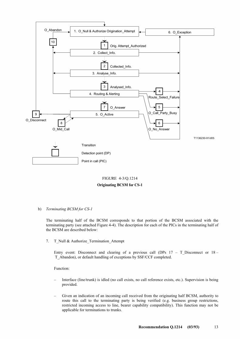
The BCSM for CS-1 described in this subclause is based on the overall BCSM in Annex A/Q.1204, refined as applicable to CS-1. It reflects the functional separation between the originating and terminating portions of calls as illustrated in Figures 4-3 and 4-4. These figures show an originating half BCSM and a terminating half BCSM, each of which is managed by a functionally separate BCM in the SSF/CCF. The description is a starting point to identify the aspects of the BCSM that are visible to IN service logic instances, and the nature of the information flows between the SSF/CCF and SCF (see 6).
In the following descriptions, the PICs are related at a high level to Q.931 ISDN call states. This is not intended to be a detailed formal definition of the relation between the PICs and Q.931 ISDN call states, but is intended as a point of reference to use in understanding the PICs. In particular, there are a number of possible ways in which the Q.931 call states may be traversed in certain situations which are not considered below.
In order to maintain uniqueness of DP names between the originating and terminating half BCSMs, �O� and �T� is prefixed to certain originating and terminating DP names, respectively.
For ease of reference, the DPs associated with the transition implied by each entry and exit event for each PIC are listed along with the PIC descriptions. When in PIC processing an exit event is detected it is for further study.
10 Recommendation Q.1214 (03/93)
a) Originating BCSM for CS-1 The originating half of the BCSM corresponds to that portion of the BCSM associated with the
originating party (see Figure 4-3). The description for each of the PICs in the originating half of the BCSM are described below: 1. O_Null & Authorize_Origination_Attempt Entry event: Disconnect and clearing of a previous call (DPs 9 � O_Disconnect and 10 �
O_Abandon), or default handling of exceptions by SSF/CCF completed. Functions:
� Interface (line/trunk) is idled (no call exists, no call reference exists, etc.) Supervision is being provided.
� Given an indication from an originating party of a desire to place an outgoing call (e.g. offhook, Q.931 Setup message, ISDN-UP IAM message), the authority/ability of the party to place the call with given properties (e.g. bearer capability, line restrictions) is verified. The types of authorization to be performed may vary for different types of originating resources (e.g. for lines vs. trunks).
Exit event: � Indication of desire to place outgoing call (e.g. offhook, Q.931 Setup message, ISDN-UP
IAM message) and authority/ability to place outgoing call verified (DP 1 � Origination_Attempt_Authorized)
� Authority/ability to place outgoing call denied (Exception) Corresponding Q.931 call state: 0. Null 2. Collect_Information Entry event: Indication of desire to place outgoing call (e.g. offhook, Q.931 Setup message,
ISDN-UP IAM message) and authority/ability to place outgoing call verified (DP 1 � Origination_Attempt_Authorized)
Functions: � Initial information package/dialling string (e.g. service codes, prefixes, dialled address digits)
being collected from originating party. Information being examined according to dialling plan to determine end of collection. No further action may be required if an en bloc signalling method is in use (e.g. an ISDN user using en bloc signalling, an incoming SS No. 7 trunk).
Exit events: � Availability of complete initial information package/dialling string from originating party. (This
event may have already occurred in the case of en bloc signalling, in which case the waiting duration in this PIC is zero.) (DP 2 � Collected_Info)
� Originating party abandons call. (10 � O_Abandon) � Information collection error has occurred (e.g. invalid dial string format, digit collection
time-out) (Exception) Comment: Some digit analysis is required to determine the end of dialling. However, it is assumed
that this analysis may be modelled as separable from the rest of digit analysis, which occurs in PIC 3, Analyse_Information. There is no intention to specify an implementation. However, a switch should externally present the separable view described for closed numbering plans.2)
Corresponding Q.931 call state: 1. Call initiated and (optionally) 2. Overlap sending
_______________ 2) This separable view is provided by supporting distinct DPs for DP 2 (Collected_Info) and DP 3 (Analysed_Info), and by
populating information flows accordingly for corresponding TDP and EDP information flows to the SCF.
Recommendation Q.1214 (03/93) 11
3. Analyse_Information
Entry event: Availability of complete initial information package/dialling string from originating party. (DP 2 � Collected_Info)
Function: Information being analysed and/or translated according to dialling plan to determine routing address and call type (e.g. local exchange call, transit exchange call, international exchange call).
Exit events:
� Availability of routing address and nature of address. (DP 3 � Analysed_Info)
� Originating party abandons calls. (DP 10 � O_Abandon)
� Unable to analyse and translate dial string in the dialling plan (e.g. invalid dial string) (Exception)
Comments:
� Note that routing address does not necessarily mean that the final physical route has been determined (e.g. route list has not been searched, hunt groups have not yet been searched, directory number has not yet been translated to physical port address), though this may be the case (e.g. when routing to a specific private facility).
Corresponding Q.931 call state: Not applicable
4. Routing and alerting (encompasses the following general BCSM PICs: Select_Route, Authorize_Call_Setup, Call_Sent, and O_Alerting)
Entry events:
� Availability of routing address and call type. (DP 3 � Analysed_Info)
Functions:
� Routing address and call type being interpreted. The next route is being selected. This may involve sequentially searching a route list, translating a directory number into physical port address, etc. The individual destination resource out of a resource group (e.g. a multi-line hunt group, a trunk group) is not selected. In some cases (e.g. an analogue line interface), a single resource (not a group) is selected.
� Authority of originating party to place this particular call being verified (e.g. checking business group restrictions, toll restrictions, route restrictions). The types of authorization checks to be performed may depend upon the type of originating resource (e.g. line vs. trunk).
� Call is being processed by the terminating half BCSM. Continued processing of call setup (e.g. ringing, audible ring indication) is taking place. Waiting for indication from terminating half BCSM that the call has been answered by terminating party.
Exit events:
� Indication from the terminating half BCSM that the call is accepted and answered by terminating party (e.g. terminating party goes offhook, Q.931 connect message received, ISDN-UP answer message received) (DP 7 � O_Answer)
� Unable to select a route (e.g. unable to determine a correct route, no more routes on route list) or indication from the terminating half BCSM that call cannot be presented to the terminating party (e.g. network congestion) (DP 4 � Route_Select_Failure)
� Indication from the terminating half BCSM that the terminating party is busy (DP 5 � O_Called_Party_Busy)
� Indication from the terminating half BCSM that the terminating party does not answer within a specified time period (DP 6 � O_No_Answer)
12 Recommendation Q.1214 (03/93)
� Originating party abandons call (DP 10 � O_Abandon) � Authority of calling party to place this call is denied (e.g. business group restriction mismatch,
toll restricted calling line) (Exception) Corresponding Q.931 call state: 4. Call delivered 5. O_Active Entry event: Indication from the terminating half BCSM that the call is accepted and answered by
terminating party. (DP 7 � O_Answer) Function: Connection established between originating and terminating party. Message
accounting/charging data may be being collected. Call supervision is being provided. Exit events:
� A service/service feature request is received from the originating party (e.g. DTMF, hook flash, ISDN feature activator, Q.931 HOLD or RETrieve message). (DP 8 � O_Mid_Call)
� A disconnect indication (e.g. onhook, Q.931 disconnect message, SS7 release message) is received from the originating party, or received from the terminating party via the terminating half BCSM. (DP 9 � O_Disconnect)
� A connection failure occurs (Exception) Comments:
� A terminating party may disconnect then reconnect before the expiration of disconnect timing. In this case, the call is considered to remain in the O_Active PIC.
� Disconnect indications and treatment are asymmetrical in the way disconnect timing is applied. Disconnect treatment and timing is different for call attempts originating from ISDN and analogue line interfaces.
Corresponding Q.931 call state: 10. Active Q.931 call states corresponding to disconnect: 11. Disconnect request, 12. Disconnect indication and
19. Release request. 6. O_Exception Entry event: An exception condition is encountered (as described above for each PIC) Function: Default handling of the exception condition is being provided. This includes general
actions necessary to ensure no resources remain inappropriately allocated, such as: � If any relationships exist between the SSF and SCF(s), send an error information flow to the
SCF(s) closing the relationships and indicating that any outstanding call handling instructions will not run to completion (e.g. see Annex B).3)
� If an SCF previously requested that call parameters be provided at the end of the call (see the call information request information flow in 6), these should be included in the error information flow.
� The SSF/CCF should make use of vendor-specific procedures to ensure release of resources within the SSF/CCF so that line, trunk, and other resources are made available for new calls.
Exit event: Default handling of the exception condition by SSF/CCF completed (Transition to O_Null & Authorize_Origination_Attempt PIC).
_______________ 3) This should be handled in the physical plane via an ABORT protocol procedure to close the relationship (i.e. close the TCAP
transaction) and indicate that any outstanding operations will not be run to completion.
Recommendation Q.1214 (03/93) 13
9
7 5
3
1
4
2
6
10
8
T1136230-91/d05
O_Abandon6. O_Exception
Route_Select_Failure
O_Call_Party_Busy
O_No_Answer
O_Disconnect
O_Mid_Call
Orig. Attempt_Authorized
Collected_Info.
Analysed_Info.
O_Answer
1. O_Null & Authorize Origination_Attempt
2. Collect_Info.
3. Analyse_Info.
4. Routing & Alerting
5. O_Active
Transition
Detection point (DP)
Point in call (PIC)
FIGURE 4-3/Q.1214Originating BCSM for CS-1
FIGURE 4-3/Q.1214...[D05] = 14.5 CM
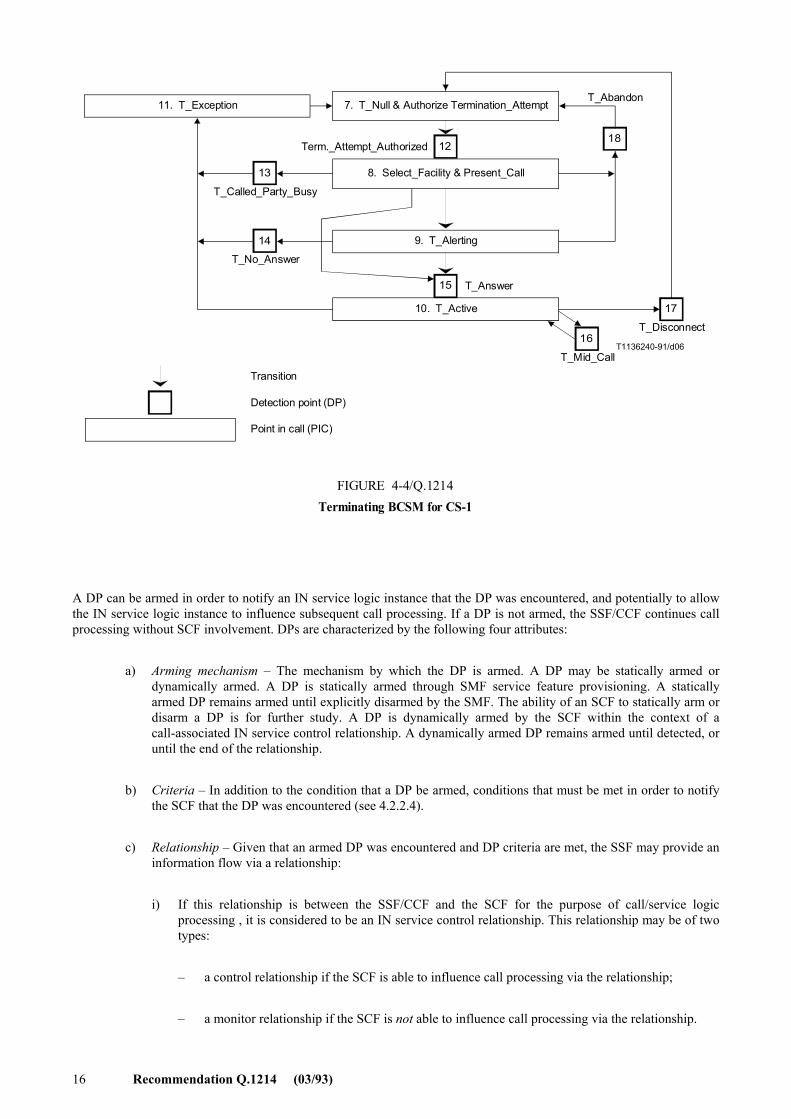
b) Terminating BCSM for CS-1
The terminating half of the BCSM corresponds to that portion of the BCSM associated with the terminating party (see attached Figure 4-4). The description for each of the PICs in the terminating half of the BCSM are described below:
7. T_Null & Authorize_Termination_Attempt
Entry event: Disconnect and clearing of a previous call (DPs 17 � T_Disconnect or 18 � T_Abandon), or default handling of exceptions by SSF/CCF completed.
Function:
� Interface (line/trunk) is idled (no call exists, no call reference exists, etc.). Supervision is being provided.
� Given an indication of an incoming call received from the originating half BCSM, authority to route this call to the terminating party is being verified (e.g. business group restrictions, restricted incoming access to line, bearer capability compatibility). This function may not be applicable for terminations to trunks.
14 Recommendation Q.1214 (03/93)
Exit event:
� Indication of incoming call received from originating half BCSM and authority to route call to a specified terminating resource (or group) verified. (DP 12 � Term_Attempt_Authorized)
� Indication of incoming call received from originating half BCSM and authority to route call to specified terminating resource (or group) denied. (Exception)
Corresponding Q.931 call state: 0. Null
8. Select_Facility & Present_Call
Entry event: Indication of incoming call received from originating half BCSM and authority to route call to a specified terminating resource (or group) verified. (DP 12 � Term_Attempt_Authorized)
Functions:
� A particular available resource in the specified resource group is being selected. It is possible that all resources in the group could be busy. A single resource is treated as a group of size 1.
� Terminating resource informed of incoming call (e.g. line seizure, Q.931 Setup message, ISDN-UP IAM message). In the case of an analogue line, ringing is applied.
Exit events:
� Terminating party is being alerted (e.g. ringing being applied, Q.931 Alerting message, ISDN-UP ACM message). (Transition to T_Alerting PIC)
� All resources in group busy or busy indication received from terminating party. (DP 13 � T_Called_Party_Busy)
� Call is accepted and answered by terminating party (e.g. terminating party goes offhook, Q.931 Connect message received, ISDN-UP answer message received) (DP 15 � T_Answer)
� Indication of originating party abandon received from originating half BCSM. (DP 18 � T_Abandon)
� Cannot present call (e.g. ISDN user determined busy, ISDN-UP release message with busy cause) (Exception)
Corresponding Q.931 call state: 6. Call present
9. T_Alerting
Entry event: Terminating party is being alerted of incoming call
Function: An indication is sent to the originating half BCSM that the terminating party is being alerted. Continued processing of call setup (e.g. ringing, audible ring indication) is taking place. Waiting for the call to be answered by terminating party.
Exit events:
� Terminating party does not answer within a specified duration. (DP 14 � T_No_Answer)
� Call is accepted and answered by terminating party (e.g. terminating party goes offhook, Q.931 connect message received, ISDN-UP answer message received) (DP 15 � T_Answer)
� Indication of originating party abandon received from originating half BCSM. (DP 18 � T_Abandon)
Comment: For terminations to SS No. 7 trunk groups, this PIC is entered upon the receipt of an address complete (ACM) message.
Corresponding Q.931 call states: 7. Call received and 8. Connect request
Recommendation Q.1214 (03/93) 15
10. T_Active Entry Events: Call is accepted and answered by terminating party (e.g. terminating party goes
offhook, Q.931 Connect message received, ISDN-UP answer message received) (DP 15 � T_Answer)
Function: An indication is sent to the originating half BCSM that the terminating party has accepted and answered the call. Connection established between originating and terminating party. Call supervision is being provided.
Exit events: � A service/service feature request is received from the terminating party (e.g. DTMF, hook flash,
ISDN feature activator, Q.931 HOLD or RETrieve message). (DP 16 � T_Mid_Call) � A disconnect indication (e.g. onhook, Q.931 disconnect message, SS7 release message) is
received from the terminating party, or received from the originating party via the originating half BCSM. (DP 17 � T_Disconnect)
� A connection failure occurs. (Exception) Comments:
� A terminating party may disconnect then reconnect before the expiration of disconnect timing. In this case, the call is considered to remain in the T_Active PIC.
� Disconnect indications and treatment are asymmetrical in the way disconnect timing is applied. Corresponding Q.931 call state: 10. Active Q.931 call states corresponding to T_Disconnect: 11. Disconnect request, 12. Disconnect indication,
and 19. Release request 11. T_Exception Entry event: An exception condition is encountered (as described above for each PIC) Function: An indication of the exception condition is sent to the originating half BCSM. Default
handling of the exception condition is being provided. This includes general actions necessary to ensure no resources remain inappropriately allocated, such as: � If any relationships exist between the SSF and SCF(s), send an error information flow to the
SCF(s) closing the relationships and indicating that any outstanding call handling instructions will not be run to completion (e.g. see Annex B).4)
� If an SCF previously requested that call parameters be provided at the end of the call (see the call information request information flow in 6), these should be included in the error information flow.
� The SSF/CCF should make use of vendor-specific procedures to ensure release of resources within the SSF/CCF so that line, trunk, and other resources are made available for new calls.
Exit event: Default handling of the exception condition by SSF/CCF completed (Transition to T_Null & Termination_Attempt_Authorized PIC).
4.2.2.3 BCSM detection points
Certain basic call and connection events may be visible to IN service logic instances. DPs are the points in call processing at which these events are detected. DPs for the BCSM are identified in 4.2.2.2.
_______________ 4) This should be handled in the physical plane via an ABORT protocol procedure to close the relationship (i.e. close the TCAP
transaction) and indicate that any outstanding operations will not be run to completion.
16 Recommendation Q.1214 (03/93)
T1136240-91/d06
13
14
1218
15
16
17
11. T_Exception
8. Select_Facility & Present_Call
9. T_Alerting
10. T_Active
7. T_Null & Authorize Termination_AttemptT_Abandon
T_Disconnect
T_Mid_Call
T_Called_Party_Busy
T_No_Answer
Term._Attempt_Authorized
T_Answer
Transition
Detection point (DP)
Point in call (PIC)
FIGURE 4-4/Q.1214Terminating BCSM for CS-1
FIGURE 4-4/Q.1214...[D06] = 11.5 CM
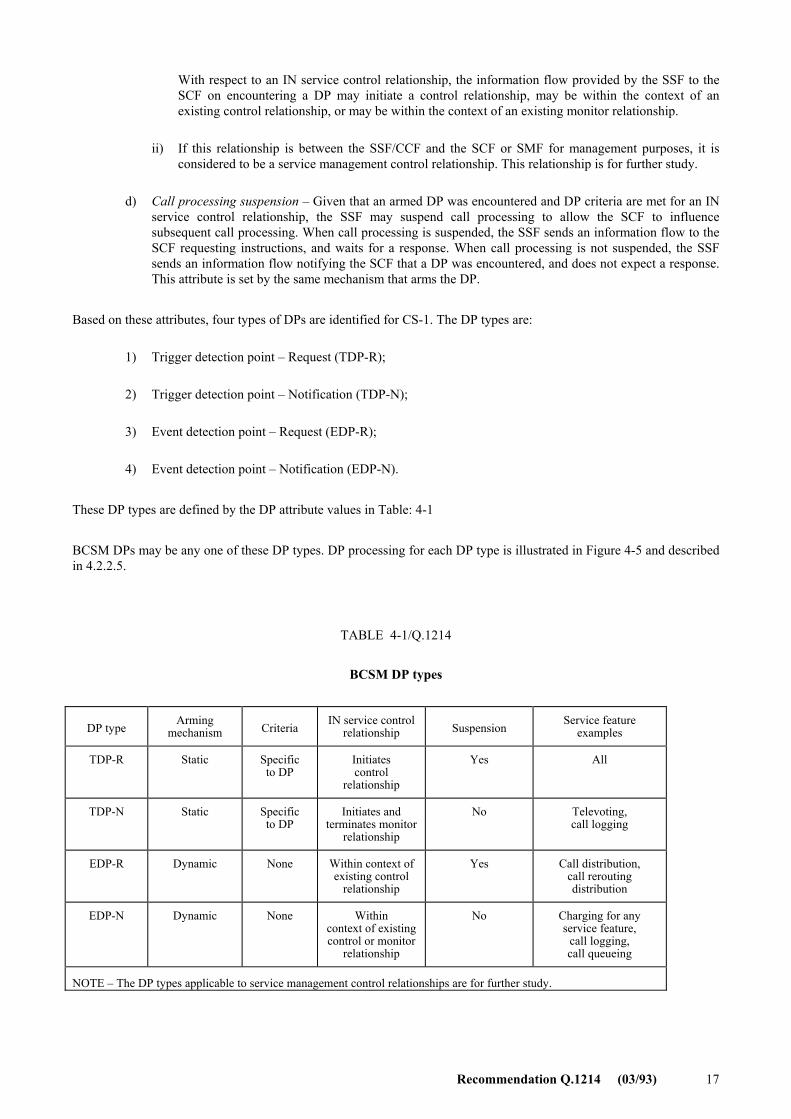
A DP can be armed in order to notify an IN service logic instance that the DP was encountered, and potentially to allow the IN service logic instance to influence subsequent call processing. If a DP is not armed, the SSF/CCF continues call processing without SCF involvement. DPs are characterized by the following four attributes:
a) Arming mechanism � The mechanism by which the DP is armed. A DP may be statically armed or dynamically armed. A DP is statically armed through SMF service feature provisioning. A statically armed DP remains armed until explicitly disarmed by the SMF. The ability of an SCF to statically arm or disarm a DP is for further study. A DP is dynamically armed by the SCF within the context of a call-associated IN service control relationship. A dynamically armed DP remains armed until detected, or until the end of the relationship.
b) Criteria � In addition to the condition that a DP be armed, conditions that must be met in order to notify the SCF that the DP was encountered (see 4.2.2.4).
c) Relationship � Given that an armed DP was encountered and DP criteria are met, the SSF may provide an information flow via a relationship:
i) If this relationship is between the SSF/CCF and the SCF for the purpose of call/service logic processing , it is considered to be an IN service control relationship. This relationship may be of two types:
� a control relationship if the SCF is able to influence call processing via the relationship;
� a monitor relationship if the SCF is not able to influence call processing via the relationship.
Recommendation Q.1214 (03/93) 17
With respect to an IN service control relationship, the information flow provided by the SSF to the SCF on encountering a DP may initiate a control relationship, may be within the context of an existing control relationship, or may be within the context of an existing monitor relationship.
ii) If this relationship is between the SSF/CCF and the SCF or SMF for management purposes, it is considered to be a service management control relationship. This relationship is for further study.
d) Call processing suspension � Given that an armed DP was encountered and DP criteria are met for an IN service control relationship, the SSF may suspend call processing to allow the SCF to influence subsequent call processing. When call processing is suspended, the SSF sends an information flow to the SCF requesting instructions, and waits for a response. When call processing is not suspended, the SSF sends an information flow notifying the SCF that a DP was encountered, and does not expect a response. This attribute is set by the same mechanism that arms the DP.
Based on these attributes, four types of DPs are identified for CS-1. The DP types are:
1) Trigger detection point � Request (TDP-R);
2) Trigger detection point � Notification (TDP-N);
3) Event detection point � Request (EDP-R);
4) Event detection point � Notification (EDP-N).
These DP types are defined by the DP attribute values in Table: 4-1
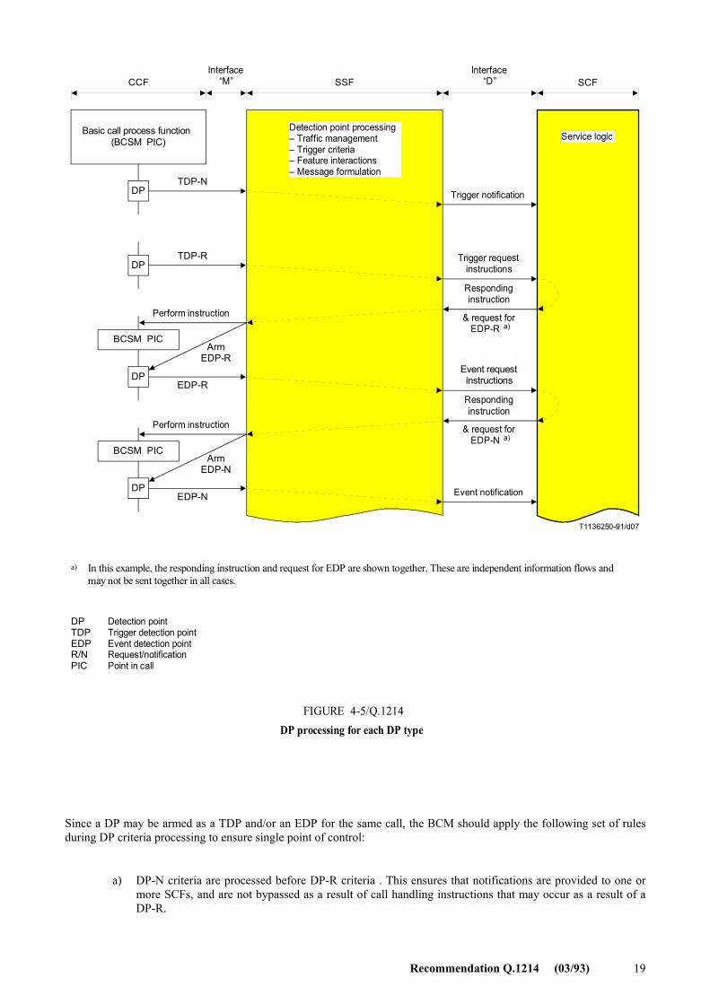
BCSM DPs may be any one of these DP types. DP processing for each DP type is illustrated in Figure 4-5 and described in 4.2.2.5.
TABLE 4-1/Q.1214
BCSM DP types
DP type Arming
mechanism Criteria IN service control
relationship Suspension Service feature
examples
TDP-R Static Specific to DP
Initiates control
relationship
Yes All
TDP-N Static Specific to DP
Initiates and terminates monitor
relationship
No Televoting, call logging
EDP-R Dynamic None Within context of existing control
relationship
Yes Call distribution, call rerouting distribution
EDP-N Dynamic None Within context of existingcontrol or monitor
relationship
No Charging for any service feature,
call logging, call queueing
NOTE � The DP types applicable to service management control relationships are for further study.
18 Recommendation Q.1214 (03/93)
4.2.2.4 DP criteria
As stated in 4.2.2.3, DP criteria are conditions that must be met in order to notify the SCF that the DP was encountered. These criteria can be assigned to a DP from the viewpoint of range of effectiveness, as identified below:
� Individual line/trunk based criteria
This type of criteria applies to each subscriber line or trunk line. For example, SCF processing is invoked when user A makes call origination. This criteria could be said to be specific for user A.
� Group based criteria
This type of criteria applies to a certain group of lines or users. For example, when a call origination from any user in a certain centrex group should invoke SCF processing the trigger should apply to that specific centrex group.
� Office based criteria
This type of criteria applies to the whole office. Any calls generated in the switching system will be subject to this criteria . For example, any call which makes access to the registered freephone number is triggered and SCF processing is invoked.
The following criteria are DP criteria for CS-1, as applicable for a given DP:
� trigger assigned (unconditional/conditional on other criteria);
� Class of service;
� specific B-channel identifier;
� specific digit strings;
� feature codes (e.g. *XX, #);
� prefixes (e.g. 0+, 00+, 0�, 00�, 011, 01, 1+);
� access codes (e.g. 8+) for customized numbering plan;
� specific abbreviated dialling strings for customized numbering plan;
� specific calling party number strings;
� specific called party number strings;
� nature of address (e.g. subscriber significant number, national significant number, international number);
� bearer capability;
� feature activation/indication (unconditional/conditional on specific feature patterns);
� facility information (unconditional/conditional on specific facility information patterns);
� cause (unconditional/conditional on specific cause patterns).
4.2.2.5 BCM DP processing
BCM DP processing involves:
� traffic management actions (see call gapping and service filtering information flows in 5 and 6);
� determining if DP criteria are met (see 4.2.2.4 and this subclause);
� handling service logic instance interactions when invoking new instances of IN and non-IN service logic (see this subclause and 4.2.4.3);
� and formulating information flows to send to one or more SCFs (see this section and Initial DP and event report information flows in sections 5 and 6).
Recommendation Q.1214 (03/93) 19
T1136250-91/d07
Basic call process function(BCSM PIC)
DP
DP
BCSM PIC
DP
BCSM PIC
DP
Interface�M�
Interface�D�CCF SSF SCF
TDP-N
TDP-R
Perform instruction
Perform instruction
Trigger notification
Trigger requestinstructions
Respondinginstruction
Event requestinstructions
Respondinginstruction
Event notification
EDP-R
EDP-N
& request forEDP-R a)a)
& request forEDP-N a)a)
Service logicDetection point processing� Traffic management� Trigger criteria� Feature interactions� Message formulation
ArmEDP-R
ArmEDP-N
In this example, the responding instruction and request for EDP are shown together. These are independent information flows andmay not be sent together in all cases.
a)
DPTDPEDP R/NPIC
Detection pointTrigger detection pointEvent detection pointRequest/notificationPoint in call
FIGURE 4-5/Q.1214DP processing for each DP type
FIGURE 4-5/Q.1214...[D07] = 20 CM
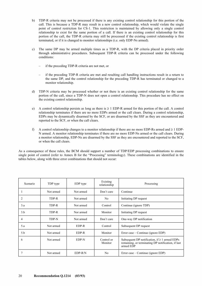
Since a DP may be armed as a TDP and/or an EDP for the same call, the BCM should apply the following set of rules during DP criteria processing to ensure single point of control:
a) DP-N criteria are processed before DP-R criteria . This ensures that notifications are provided to one or more SCFs, and are not bypassed as a result of call handling instructions that may occur as a result of a DP-R.
20 Recommendation Q.1214 (03/93)
b) TDP-R criteria may not be processed if there is any existing control relationship for this portion of the call. This is because a TDP-R may result in a new control relationship, which would violate the single point of control restriction for CS-1. This restriction is maintained by allowing only a single control relationship to exist for the same portion of a call. If there is an existing control relationship for this portion of the call, the TDP-R criteria may still be processed if the existing control relationship is first terminated, or if it is changed to monitor relationships (i.e. only EDP-Ns armed).
c) The same DP may be armed multiple times as a TDP-R, with the DP criteria placed in priority order through administrative procedures. Subsequent TDP-R criteria can be processed under the following conditions:
� if the preceding TDP-R criteria are not met, or
� if the preceding TDP-R criteria are met and resulting call handling instructions result in a return to the same DP, and the control relationship for the preceding TDP-R has terminated or changed to a monitor relationship.
d) TDP-N criteria may be processed whether or not there is an existing control relationship for the same portion of the call, since a TDP-N does not open a control relationship. This procedure has no effect on the existing control relationship.
e) A control relationship persists as long as there is ≥ 1 EDP-R armed for this portion of the call. A control relationship terminates if there are no more EDPs armed or the call clears. During a control relationship, EDPs may be dynamically disarmed by the SCF, or are disarmed by the SSF as they are encountered and reported to the SCF, or when the call clears.
f) A control relationship changes to a monitor relationship if there are no more EDP-Rs armed and ≥ 1 EDP-N armed. A monitor relationship terminates if there are no more EDP-Ns armed or the call clears. During a monitor relationship, EDP-Ns are disarmed by the SSF as they are encountered and reported to the SCF, or when the call clears.
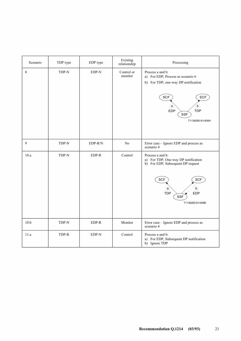
As a consequence of these rules, the BCM should support a number of TDP/EDP processing combinations to ensure single point of control (refer to Annex B for the �Processing� terminology). These combinations are identified in the tables below, along with three error combinations that should not occur:
Scenario TDP type EDP type Existing
relationship Processing
1 Not armed Not armed Don�t care Continue
2 TDP-R Not armed No Initiating DP request
3.a TDP-R Not armed Control Continue (ignore TDP)
3.b TDP-R Nor armed Monitor Initiating DP request
4 TDP-N Not armed Don�t care One-way DP notification
5.a Not armed EDP-R Control Subsequent DP request
5.b Not armed EDP-R Monitor Error case � Continue (ignore EDP)
6 Not armed EDP-N Control or Monitor
Subsequent DP notification, if ≥ 1 armed EDPs remaining, or terminating DP notification, if last armed EDP
7 Not armed EDP-R/N No Error case � Continue (ignore EDP)
Recommendation Q.1214 (03/93) 21
Scenario TDP type EDP type Existing
relationship Processing
8 TDP-N EDP-N Control or monitor
Process a and b: a) For EDP, Process as scenario 6 b) For TDP, one-way DP notification
Figur
a b
T1136260-91/d08A
SCF SCF
SSFEDP TDP
9 TDP-N EDP-R/N No Error case � Ignore EDP and process as scenario 4
10.a TDP-N EDP-R Control Process a and b: a) For TDP, One-way DP notification b) For EDP, Subsequent DP request
a b
T1136260-91/d08B
SCF SCF
SSFTDP EDP
10.b TDP-N EDP-R Monitor Error case � Ignore EDP and process as scenario 4
11.a TDP-R EDP-N Control Process a and b: a) For EDP, Subsequent DP notification b) Ignore TDP
22 Recommendation Q.1214 (03/93)
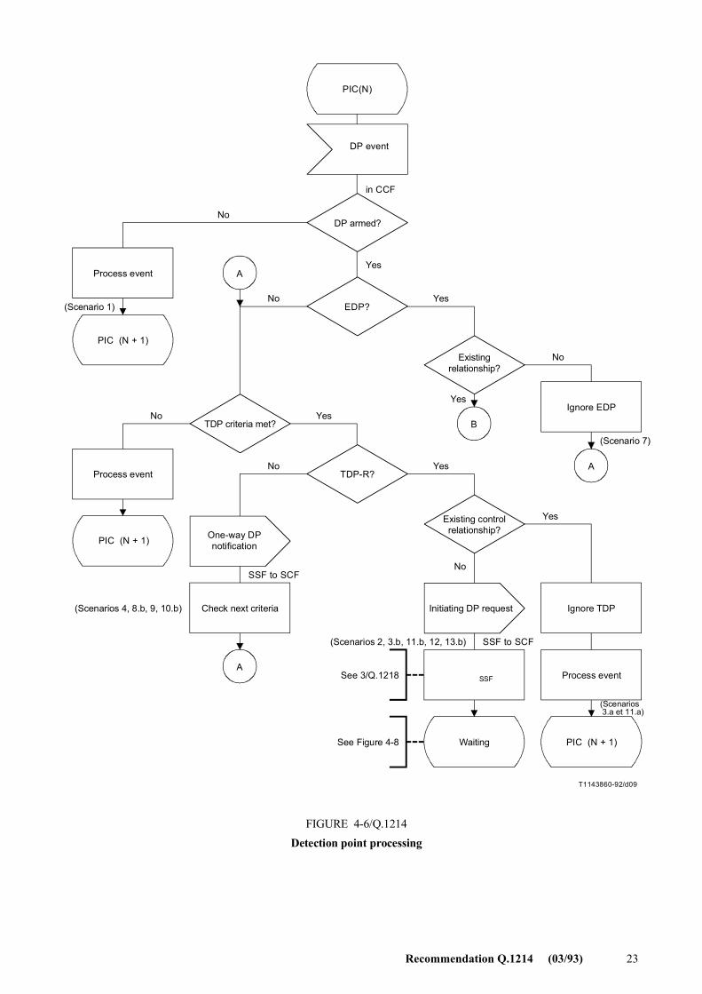
These DP processing combinations are illustrated in the SDL diagrams in Figures 4-6 through 4-10.
4.2.3 IN-switching manager (IN-SM)
A brief description of the IN-SM is provided in 4.2. The IN-SM centres around the IN-switching state model (IN-SSM) which provides a description of SSF/CCF IN call/connection processing in terms of IN call/connection states. Object-oriented techniques are used to describe the IN-SSM, based on the concepts and principles outlined in Annex B/Q.1204.
The IN-SM subjects described in the following subclauses include the IN-SSM, IN-SSM events that can be reported to active IN service logic instances, and SSF resource control. A high-level description of these subjects is provided.
4.2.3.1 IN-Switching state model (IN-SSM)
The IN-SSM provides an object-oriented finite state machine description of SSF/CCF IN call/connection processing in terms of IN call/connection states. It provides a framework for describing the scope of view and control of SSF/CCF activities offered to an SCF. The extent to which the IN-SSM is visible to the SCF is defined by the information flows identified for CS-1 between the SSF/CCF and SCF. Though this framework is consistent with the scope of CS-1 as identified in Recommendation Q.1211, not all of the capabilities implied by the IN-SSM are supported by the information flows and information elements defined in 6. In particular, the information flows for manipulating individual call parties, and information elements reflecting IN-SSM call/connection states, are for further study. A starting point for these studies is contained in Appendix I.
IN call/connection states can be described in terms of the IN-SSM, which defines the set of SSF/CCF objects visible to the SCF. Each IN-SSM instance provides the SCF with a limited aperture of visibility and influence into SSF/CCF IN call/connection processing. This aperture of visibility and influence is defined by the objects that constitute the IN-SSM. These objects are abstractions of SSF/CCF resources accessible to the SCF.
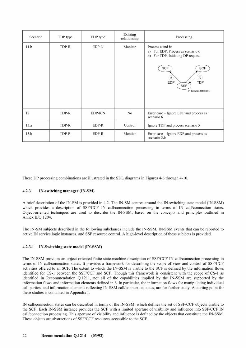
Scenario TDP type EDP type Existing
relationship Processing
11.b TDP-R EDP-N Monitor Process a and b: a) For EDP, Process as scenario 6 b) For TDP, Initiating DP request
a b
T1136260-91/d08C
SCF SCF
SSFEDP TDP
12 TDP-R EDP-R/N No Error case � Ignore EDP and process as scenario 6
13.a TDP-R EDP-R Control Ignore TDP and process scenario 5
13.b TDP-R EDP-R Montior Error case � Ignore EDP and process as scenario 3.b
Recommendation Q.1214 (03/93) 23
T1143860-92/d09
A
B
A
A
PIC(N)
Process event
PIC (N + 1)
EDP?
TDP criteria met?
Existingrelationship?
Ignore EDP
Process event TDP-R?
Existing controlrelationship?
PIC (N + 1) One-way DPnotification
Check next criteria Initiating DP request Ignore TDP
Set TSSFSSF Process event
Waiting PIC (N + 1)
in CCF
Yes
SSF to SCF
SSF to SCF
No
No Yes
No
No Yes
No Yes
Yes
Yes
No
(Scenario 1)
(Scenario 7)
(Scenarios 3.a et 11.a)
(Scenarios 4, 8.b, 9, 10.b)
(Scenarios 2, 3.b, 11.b, 12, 13.b)
See 3/Q.1218
See Figure 4-8
FIGURE 4-6/Q.1214Detection point processing
DP armed?
DP event
FIGURE 4-6/Q.1214...[D09] = 21 CM PLEINE PAGE
24 Recommendation Q.1214 (03/93)
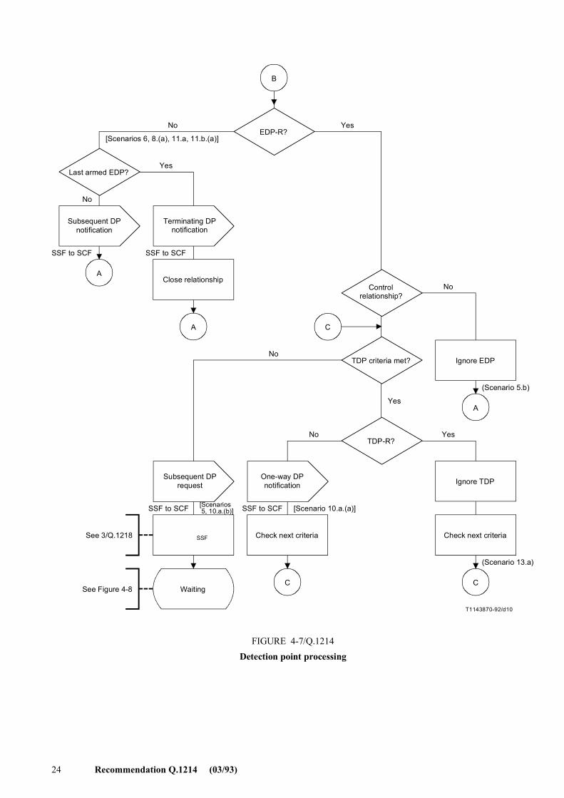
B
A
A
A
C
CC
T1143870-92/d10
EDP-R?
Last armed EDP?
Subsequent DPnotification
Terminating DPnotification
Close relationshipControl
relationship?
TDP criteria met? Ignore EDP
TDP-R?
Ignore TDPSubsequent DP
requestOne-way DPnotification
Check next criteria Check next criteria
Waiting
Set TSSFSSF
No Yes
Yes
No
No
No Yes
[Scenarios 6, 8.(a), 11.a, 11.b.(a)]
Yes
(Scenario 5.b)
(Scenario 13.a)
[Scenarios 5, 10.a.(b)] [Scenario 10.a.(a)]
No
SSF to SCF SSF to SCF
SSF to SCF SSF to SCF
See 3/Q.1218
See Figure 4-8
FIGURE 4-7/Q.1214Detection point processing
FIGURE 4-7/Q.1214...[D10] = 21 CM PLEINE PAGE
Recommendation Q.1214 (03/93) 25
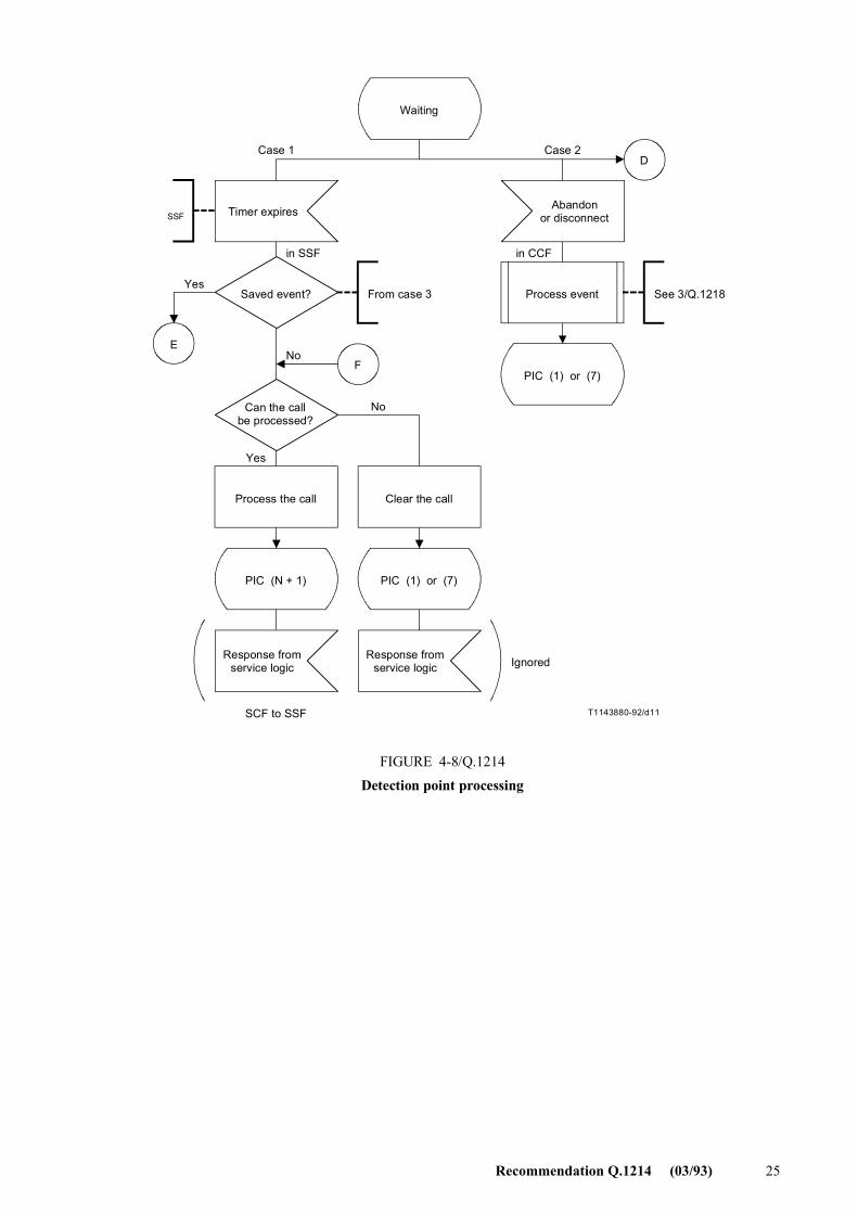
T1143880-92/d11
E
D
F
Waiting
Timer expires Abandonor disconnect
Saved event? Process event
PIC (1) or (7)
Can the callbe processed?
Process the call Clear the call
PIC (N + 1) PIC (1) or (7)
Response fromservice logic
Response fromservice logic
Yes
No
in SSF
From case 3
No
Ignored
See 3/Q.1218
SCF to SSF
Yes
in CCF
TSSFSSF
FIGURE 4-8/Q.1214Detection point processing
Case 1 Case 2
FIGURE 4-8/Q.1214...[D11] = 17.5 CM
26 Recommendation Q.1214 (03/93)
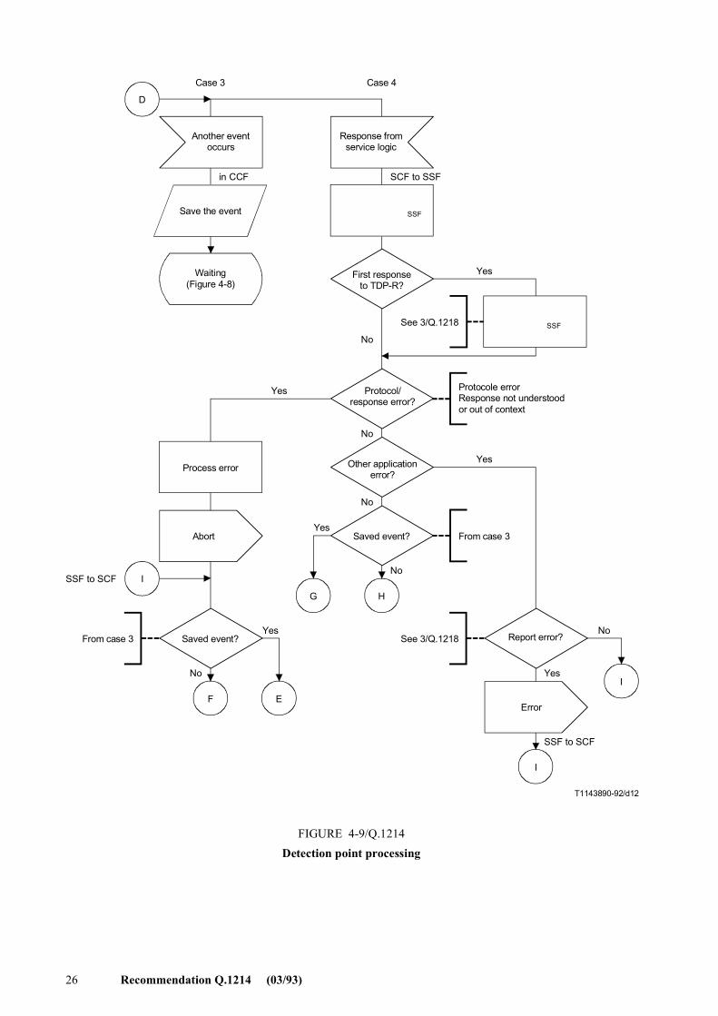
D
I
F E
G H
I
T1143890-92/d12
I
Another eventoccurs
Response fromservice logic
Save the event
Waiting(Figure 4-8)
Cancel timer TSSFSSF
First responseto TDP-R?
Reset TSSFSSF
Protocol/response error?
Other applicationerror?
Saved event?
Report error?
Error
Process error
Abort
Saved event?
Case 3 Case 4
Yes
Yes
Yes
Yes
Yes
in CCF SCF to SSF
Protocole errorResponse not understoodor out of context
From case 3
No
Yes
See 3/Q.1218
No
No
No
See 3/Q.1218
SSF to SCF
From case 3
No
No
SSF to SCF
FIGURE 4-9/Q.1214Detection point processing
FIGURE 4-9/Q.1214...[D12] = 21 CM PLEINE PAGE
Recommendation Q.1214 (03/93) 27
T1143900-92/d13
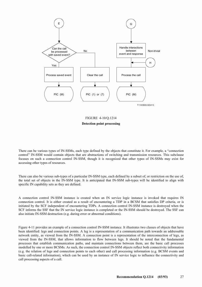
E G
H
Can the callbe processed
with saved event?No
Handle interactionsbetween
event and response
Process the callClear the callProcess saved event
PIC (M) PIC (1) or (7) PIC (M)
Non-trivial
Yes
FIGURE 4-10/Q.1214Detection point processing
FIGURE 4-10/Q.1214...[D13] = 11 CM
There can be various types of IN-SSMs, each type defined by the objects that constitute it. For example, a �connection control� IN-SSM would contain objects that are abstractions of switching and transmission resources. This subclause focuses on such a connection control IN-SSM, though it is recognized that other types of IN-SSMs may exist for accessing other types of resources.
There can also be various sub-types of a particular IN-SSM type, each defined by a subset of, or restriction on the use of, the total set of objects in the IN-SSM type. It is anticipated that IN-SSM sub-types will be identified to align with specific IN capability sets as they are defined.
A connection control IN-SSM instance is created when an IN service logic instance is invoked that requires IN connection control. It is either created as a result of encountering a TDP in a BCSM that satisfies DP criteria, or is initiated by the SCF independent of encountering TDPs. A connection control IN-SSM instance is destroyed when the SCF informs the SSF that the IN service logic instance is completed or the IN-SSM should be destroyed. The SSF can also initiate IN-SSM destruction (e.g. during error or abnormal conditions).
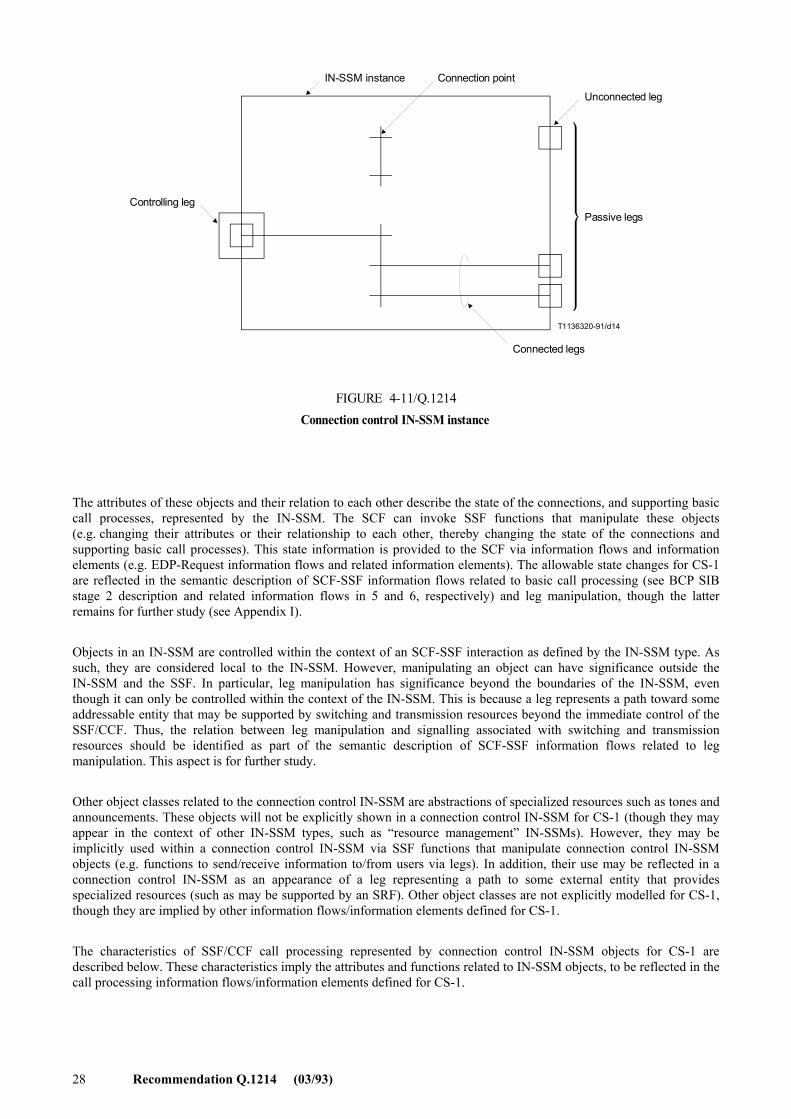
Figure 4-11 provides an example of a connection control IN-SSM instance. It illustrates two classes of objects that have been identified: legs and connection points. A leg is a representation of a communication path towards an addressable network entity, as viewed from the IN-SSM. A connection point is a representation of the interconnection of legs, as viewed from the IN-SSM, that allows information to flow between legs. It should be noted that the fundamental processes that establish communication paths, and maintain connections between them, are the basic call processes modelled by one or more BCSMs. As such, the connection control IN-SSM objects reflect both connectivity information (e.g. the relation of legs and connection points to each other) and call processing information (e.g. BCSM events and basic call-related information), which can be used by an instance of IN service logic to influence the connectivity and call processing aspects of a call.
28 Recommendation Q.1214 (03/93)
T1136320-91/d14
IN-SSM instance Connection point
Unconnected leg
Passive legs
Connected legs
Controlling leg
FIGURE 4-11/Q.1214Connection control IN-SSM instance
FIGURE 4-11/Q.1214...[D14] = 9.5 CM
The attributes of these objects and their relation to each other describe the state of the connections, and supporting basic call processes, represented by the IN-SSM. The SCF can invoke SSF functions that manipulate these objects (e.g. changing their attributes or their relationship to each other, thereby changing the state of the connections and supporting basic call processes). This state information is provided to the SCF via information flows and information elements (e.g. EDP-Request information flows and related information elements). The allowable state changes for CS-1 are reflected in the semantic description of SCF-SSF information flows related to basic call processing (see BCP SIB stage 2 description and related information flows in 5 and 6, respectively) and leg manipulation, though the latter remains for further study (see Appendix I).
Objects in an IN-SSM are controlled within the context of an SCF-SSF interaction as defined by the IN-SSM type. As such, they are considered local to the IN-SSM. However, manipulating an object can have significance outside the IN-SSM and the SSF. In particular, leg manipulation has significance beyond the boundaries of the IN-SSM, even though it can only be controlled within the context of the IN-SSM. This is because a leg represents a path toward some addressable entity that may be supported by switching and transmission resources beyond the immediate control of the SSF/CCF. Thus, the relation between leg manipulation and signalling associated with switching and transmission resources should be identified as part of the semantic description of SCF-SSF information flows related to leg manipulation. This aspect is for further study.
Other object classes related to the connection control IN-SSM are abstractions of specialized resources such as tones and announcements. These objects will not be explicitly shown in a connection control IN-SSM for CS-1 (though they may appear in the context of other IN-SSM types, such as �resource management� IN-SSMs). However, they may be implicitly used within a connection control IN-SSM via SSF functions that manipulate connection control IN-SSM objects (e.g. functions to send/receive information to/from users via legs). In addition, their use may be reflected in a connection control IN-SSM as an appearance of a leg representing a path to some external entity that provides specialized resources (such as may be supported by an SRF). Other object classes are not explicitly modelled for CS-1, though they are implied by other information flows/information elements defined for CS-1.
The characteristics of SSF/CCF call processing represented by connection control IN-SSM objects for CS-1 are described below. These characteristics imply the attributes and functions related to IN-SSM objects, to be reflected in the call processing information flows/information elements defined for CS-1.
Recommendation Q.1214 (03/93) 29
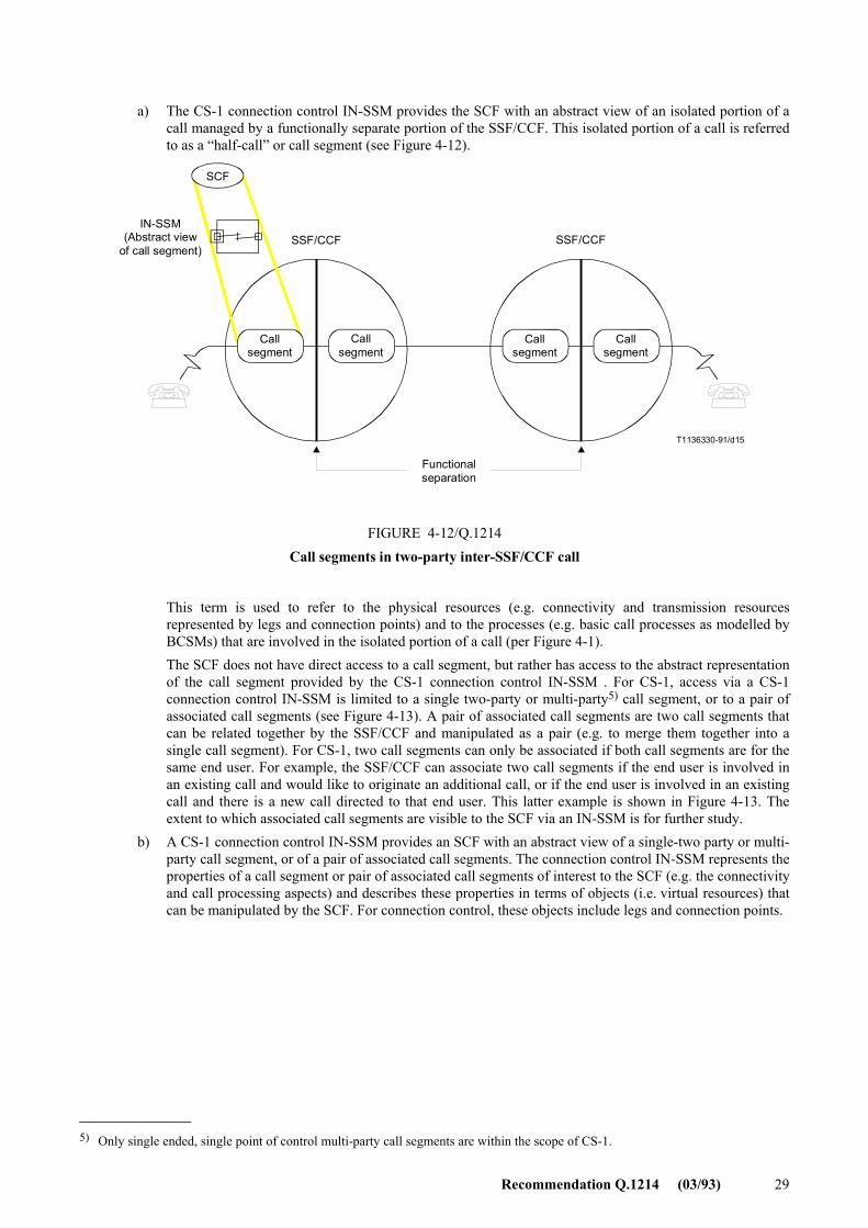
a) The CS-1 connection control IN-SSM provides the SCF with an abstract view of an isolated portion of a
call managed by a functionally separate portion of the SSF/CCF. This isolated portion of a call is referred to as a �half-call� or call segment (see Figure 4-12).
T1136330-91/d15
SCF
Functionalseparation
Callsegment
Callsegment
Callsegment
Callsegment
IN-SSM(Abstract view
of call segment)SSF/CCF SSF/CCF
FIGURE 4-12/Q.1214Call segments in two-party inter-SSF/CCF call
This term is used to refer to the physical resources (e.g. connectivity and transmission resources
represented by legs and connection points) and to the processes (e.g. basic call processes as modelled by BCSMs) that are involved in the isolated portion of a call (per Figure 4-1).
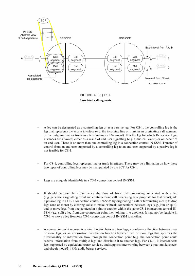
The SCF does not have direct access to a call segment, but rather has access to the abstract representation of the call segment provided by the CS-1 connection control IN-SSM . For CS-1, access via a CS-1 connection control IN-SSM is limited to a single two-party or multi-party5) call segment, or to a pair of associated call segments (see Figure 4-13). A pair of associated call segments are two call segments that can be related together by the SSF/CCF and manipulated as a pair (e.g. to merge them together into a single call segment). For CS-1, two call segments can only be associated if both call segments are for the same end user. For example, the SSF/CCF can associate two call segments if the end user is involved in an existing call and would like to originate an additional call, or if the end user is involved in an existing call and there is a new call directed to that end user. This latter example is shown in Figure 4-13. The extent to which associated call segments are visible to the SCF via an IN-SSM is for further study.
b) A CS-1 connection control IN-SSM provides an SCF with an abstract view of a single-two party or multi-party call segment, or of a pair of associated call segments. The connection control IN-SSM represents the properties of a call segment or pair of associated call segments of interest to the SCF (e.g. the connectivity and call processing aspects) and describes these properties in terms of objects (i.e. virtual resources) that can be manipulated by the SCF. For connection control, these objects include legs and connection points.
_______________ 5) Only single ended, single point of control multi-party call segments are within the scope of CS-1.
30 Recommendation Q.1214 (03/93)
T1136340-91/d16
A
C
B
SCF
SSF/CCF SSF/CCF
Existing call from A to B
New call from C to A
IN-SSM(Abstract view
of call segments)
FIGURE 4-13/Q.1214Associated call segments
Callsegment
Callsegment
Callsegment
Callsegment
Callsegment
Callsegment
Callsegment
Callsegment
Associatedcall segments
FIGURE 4-13/Q.1214...[D16] = 9.5 CM
� A leg can be designated as a controlling leg or as a passive leg. For CS-1, the controlling leg is the leg that represents the access interface (e.g. the incoming line or trunk in an originating call segment, or the outgoing line or trunk in a terminating call Segment). It is the leg for which IN service logic instances are invoked, either as a result of end user signalling (e.g. a mid-call event) or on behalf of an end user. There is no more than one controlling leg in a connection control IN-SSM. Transfer of control from an end user supported by a controlling leg to an end user supported by a passive leg is not feasible for CS-1.
� For CS-1, controlling legs represent line or trunk interfaces. There may be a limitation on how these two types of controlling legs may be manipulated by the SCF for CS-1.
� Legs are uniquely identifiable in a CS-1 connection control IN-SSM.
� It should be possible to: influence the flow of basic call processing associated with a leg (e.g. generate a signalling event and continue basic call processing as appropriate for that event); add a passive leg to a CS-1 connection control IN-SSM by originating a call or terminating a call; to drop legs (one or more) by clearing calls; to make or break connections between legs (e.g. join or split); and to move legs from one connection point to another within the same CS-1 connection control IN-SSM (e.g. split a leg from one connection point then joining it to another). It may not be feasible in CS-1 to move a leg from one CS-1 connection control IN-SSM to another.
� A connection point represents a joint function between two legs, a conference function between three or more legs, or an information distribution function between two or more legs that specifies the directionality of information flow through the connection point (e.g. the connection point could receive information from multiple legs and distribute it to another leg). For CS-1, it interconnects legs supported by equivalent bearer services, and supports interworking between circuit mode/speech and circuit mode/3.1 kHz audio bearer services.
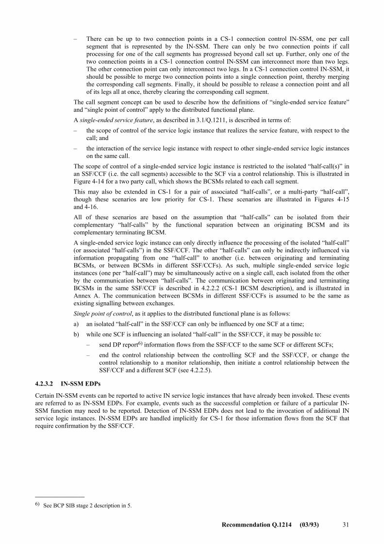
Recommendation Q.1214 (03/93) 31
� There can be up to two connection points in a CS-1 connection control IN-SSM, one per call segment that is represented by the IN-SSM. There can only be two connection points if call processing for one of the call segments has progressed beyond call set up. Further, only one of the two connection points in a CS-1 connection control IN-SSM can interconnect more than two legs. The other connection point can only interconnect two legs. In a CS-1 connection control IN-SSM, it should be possible to merge two connection points into a single connection point, thereby merging the corresponding call segments. Finally, it should be possible to release a connection point and all of its legs all at once, thereby clearing the corresponding call segment.
The call segment concept can be used to describe how the definitions of �single-ended service feature� and �single point of control� apply to the distributed functional plane.
A single-ended service feature, as described in 3.1/Q.1211, is described in terms of: � the scope of control of the service logic instance that realizes the service feature, with respect to the
call; and � the interaction of the service logic instance with respect to other single-ended service logic instances
on the same call. The scope of control of a single-ended service logic instance is restricted to the isolated �half-call(s)� in
an SSF/CCF (i.e. the call segments) accessible to the SCF via a control relationship. This is illustrated in Figure 4-14 for a two party call, which shows the BCSMs related to each call segment.
This may also be extended in CS-1 for a pair of associated �half-calls�, or a multi-party �half-call�, though these scenarios are low priority for CS-1. These scenarios are illustrated in Figures 4-15 and 4-16.
All of these scenarios are based on the assumption that �half-calls� can be isolated from their complementary �half-calls� by the functional separation between an originating BCSM and its complementary terminating BCSM.
A single-ended service logic instance can only directly influence the processing of the isolated �half-call� (or associated �half-calls�) in the SSF/CCF. The other �half-calls� can only be indirectly influenced via information propagating from one �half-call� to another (i.e. between originating and terminating BCSMs, or between BCSMs in different SSF/CCFs). As such, multiple single-ended service logic instances (one per �half-call�) may be simultaneously active on a single call, each isolated from the other by the communication between �half-calls�. The communication between originating and terminating BCSMs in the same SSF/CCF is described in 4.2.2.2 (CS-1 BCSM description), and is illustrated in Annex A. The communication between BCSMs in different SSF/CCFs is assumed to be the same as existing signalling between exchanges.
Single point of control, as it applies to the distributed functional plane is as follows: a) an isolated �half-call� in the SSF/CCF can only be influenced by one SCF at a time; b) while one SCF is influencing an isolated �half-call� in the SSF/CCF, it may be possible to:
� send DP report6) information flows from the SSF/CCF to the same SCF or different SCFs; � end the control relationship between the controlling SCF and the SSF/CCF, or change the
control relationship to a monitor relationship, then initiate a control relationship between the SSF/CCF and a different SCF (see 4.2.2.5).
4.2.3.2 IN-SSM EDPs
Certain IN-SSM events can be reported to active IN service logic instances that have already been invoked. These events are referred to as IN-SSM EDPs. For example, events such as the successful completion or failure of a particular IN-SSM function may need to be reported. Detection of IN-SSM EDPs does not lead to the invocation of additional IN service logic instances. IN-SSM EDPs are handled implicitly for CS-1 for those information flows from the SCF that require confirmation by the SSF/CCF.
_______________ 6) See BCP SIB stage 2 description in 5.
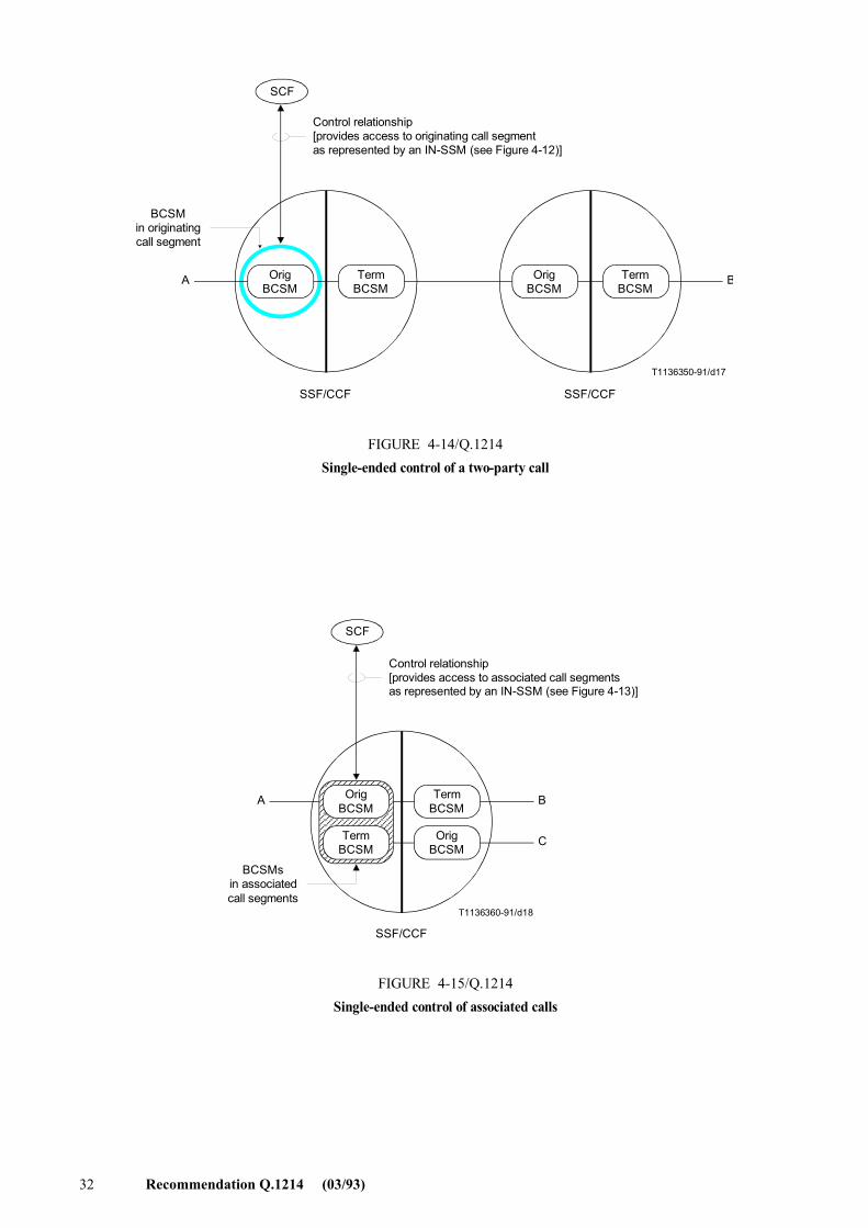
32 Recommendation Q.1214 (03/93)
A B
T1136350-91/d17
SCF
OrigBCSM
TermBCSM
OrigBCSM
TermBCSM
SSF/CCF SSF/CCF
Control relationship[provides access to originating call segmentas represented by an IN-SSM (see Figure 4-12)]
BCSMin originatingcall segment
FIGURE 4-14/Q.1214Single-ended control of a two-party call
FIGURE 4-14/Q.1214...[D17] = 9.5 CM
A
C
B
T1136360-91/d18
SCF
OrigBCSM
TermBCSM
TermBCSM
OrigBCSM
SSF/CCF
Control relationship[provides access to associated call segmentsas represented by an IN-SSM (see Figure 4-13)]
BCSMsin associatedcall segments
FIGURE 4-15/Q.1214Single-ended control of associated calls
FIGURE 4-15/Q.1214...[D18] = 9.5 CM
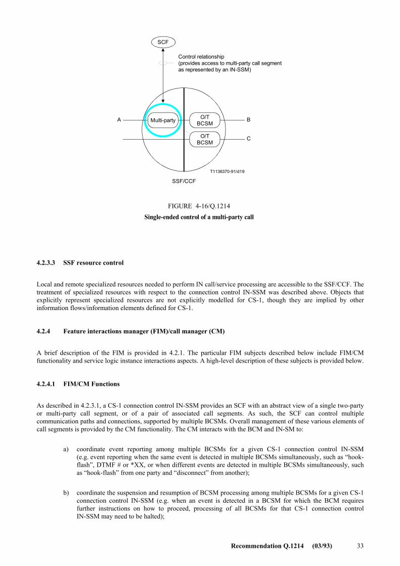
Recommendation Q.1214 (03/93) 33
A B
T1136370-91/d19
C
SCF
Multi-party O/TBCSM
O/TBCSM
SSF/CCF
Control relationship(provides access to multi-party call segmentas represented by an IN-SSM)
FIGURE 4-16/Q.1214Single-ended control of a multi-party call
FIGURE 4-16/Q.1214...[D19] = 9.5 CM
4.2.3.3 SSF resource control
Local and remote specialized resources needed to perform IN call/service processing are accessible to the SSF/CCF. The treatment of specialized resources with respect to the connection control IN-SSM was described above. Objects that explicitly represent specialized resources are not explicitly modelled for CS-1, though they are implied by other information flows/information elements defined for CS-1.
4.2.4 Feature interactions manager (FIM)/call manager (CM)
A brief description of the FIM is provided in 4.2.1. The particular FIM subjects described below include FIM/CM functionality and service logic instance interactions aspects. A high-level description of these subjects is provided below.
4.2.4.1 FIM/CM Functions
As described in 4.2.3.1, a CS-1 connection control IN-SSM provides an SCF with an abstract view of a single two-party or multi-party call segment, or of a pair of associated call segments. As such, the SCF can control multiple communication paths and connections, supported by multiple BCSMs. Overall management of these various elements of call segments is provided by the CM functionality. The CM interacts with the BCM and IN-SM to:
a) coordinate event reporting among multiple BCSMs for a given CS-1 connection control IN-SSM (e.g. event reporting when the same event is detected in multiple BCSMs simultaneously, such as �hook-flash�, DTMF # or *XX, or when different events are detected in multiple BCSMs simultaneously, such as �hook-flash� from one party and �disconnect� from another);
b) coordinate the suspension and resumption of BCSM processing among multiple BCSMs for a given CS-1 connection control IN-SSM (e.g. when an event is detected in a BCSM for which the BCM requires further instructions on how to proceed, processing of all BCSMs for that CS-1 connection control IN-SSM may need to be halted);
34 Recommendation Q.1214 (03/93)
c) enforce rules and restrictions applicable to a CS-1 connection control IN-SSM (e.g. rules and restrictions on when and how the SCF can manipulate legs, associate a pair of call segments, and merge a pair of associated call segments).
FIM functionality is described below.
d) The FIM should provide a service logic instance selection mechanism to determine which service logic instance to invoke at a DP. This mechanism should select the appropriate IN service logic instance or non-IN service logic instance, and for CS-1, may block the invocation of any other service logic instances for that particular DP (see 4.2.4.3).
e) The FIM may not always allow simultaneously active IN and non-IN service logic instance for CS-1 that control the call/connection. There are both static and dynamic mechanisms of realizing this restriction. The static mechanism may involve service management functionality (e.g. via service provisioning), whereas the dynamic mechanism may involve more complex FIM capabilities. For CS-1, the simplest mechanism should be implemented (see 4.2.4.2).
f) The FIM should provide mechanisms to support simple, restricted service logic instance interactions between simultaneously active service logic instances from different SCFs acting on the same call segment (see 4.2.4.3).
4.2.4.2 Service logic instance interactions considerations
It is recognized that services provided by an IN-structured network will be composed of one or more service features, which are constructed from one or more reusable units of capabilities (e.g. SIBs) provided to users by the network. It is also recognized that one or more service features may be simultaneously active on a single call. Finally, it is recognized that both IN service features and non-IN service features may be simultaneously active on a single call. A service feature interactions mechanism is needed to manage the potential interactions (both desirable and undesirable) between such service features. Given that these service features are realized by service logic instances, this mechanism needs to be described in terms of rules and procedures relative to triggering, compatibility, precedence, invocation, execution, and event reporting for multiple service logic instances. This subclause addresses the static and dynamic aspects of service logic instance interactions management, as well as mechanisms for determining compatibility and precedence.
a) Static and dynamic aspects
There are two aspects to service logic instance interactions management, to include the static and dynamic aspects. These two aspects are discussed below.
� Static aspects
The static aspects of service logic instance interactions management concerns the provision of service features to end users. To illustrate this, consider the following example: end user A already has service feature X, and it is known that service feature X and service feature Y are mutually incompatible; if an attempt is made to provision the invocation of a service logic instance for service feature Y to end user A using OAM procedures, then this attempt should be rejected.
� Dynamic aspects
There are three items to be considered under the dynamic aspects of service logic instance interaction management.
� If at a particular DP there is more than one service logic instance which can be invoked, then a decision must be made as to which of these service logic instances will be invoked first (i.e. service logic instance selection).
� If a service logic instance can be invoked, then a decision must be made as to whether or not the new service logic instance is compatible with any service logic instances already active on the same call segment.
Recommendation Q.1214 (03/93) 35
� If the new service logic instance is compatible with any service logic instances already active on the same call segment, then a decision must be made as to its precedence for call processing events (such as signalling messages) with respect to other active service logic instances; if the new service logic instance is incompatible, it should be blocked.
For the latter two items, there are at least two potential approaches to service logic instance interactions management.
� The first approach is to make decisions as part of DP processing; with this approach, decisions about service logic instance compatibility and precedence are made before a service logic instance is invoked.
� The second approach is to make decisions independent of DP processing; with this approach, decisions about service logic instance compatibility and precedence are made after a service logic instance is triggered.
The first approach is simpler, though restrictive, since it can prevent service logic instances from being invoked, only requiring the management of a limited number of service logic instance interactions. The second approach is more complex, though flexible, since it does not prevent service logic instance from being invoked, thus requiring a mechanism that can manage all possible service logic instance interactions. Due to this complexity, the second approach is considered beyond the scope of CS-1.
b) Mechanisms for determining compatibility and precedence
At present, knowledge concerning the compatibility of service features and their precedence is �hard-coded� in to the SSF/CCF. This mechanism relies on specifying each possible interaction for every possible combination of service features. As the number of service features gets large (one of the aims of IN), this specification quickly becomes complex, complicating the task of the service designer. Furthermore, as each new service feature is added, its many possible interactions must be identified and specific rules and data must be introduced into the SSF/CCF or SCF to specify how each interaction is to be resolved.
A more general mechanism than �hard-coding� would be a �data-driven� mechanism in which the service designer could specify service feature compatibility and precedence during service creation and provisioning. The service creation environment could provide the service designer with information about the specific service features for a particular subscriber, enabling the service designer to specify such things as which service features are blocked by a new service feature, the relative precedence of the new service feature to other service features, and the DP at which the service logic instance for the service feature should be invoked. The output of such a mechanism could be introduced directly into the SSF/CCF or SCF from the service creation environment.
The ultimate mechanism would be to use an expert system approach to reduce the burden on the service designer.
For CS-1, the existing mechanisms for service logic instance interactions management will have to be used beyond what is described in 4.2.2.5 for IN-IN service logic instance interactions in the SSF/CCF, and 4.2.4.2.c), 4.2.4.2.d), and 4.2.4.3 for IN-non IN service logic instance interactions in the SSF/CCF. That is, the interactions between service logic instances (both IN and non-IN) will have to be specified as part of the service feature description, with vendor-specific mechanisms to resolve remaining interactions in the specified manner. In addition, it may be possible to adopt a data-driven approach if mechanisms can be incorporated into the service creation environment to prompt the service designer for compatibility and precedence information, then download the appropriate data into the SSF/CCF or SCF. The expert system approach is considered to be beyond the scope of CS-1.
c) IN and non-IN service logic instance interactions
There are desirable and undesirable IN and non-IN service logic instance interactions in the SSF/CCF. The Table 4-2 identifies these for CS-1.
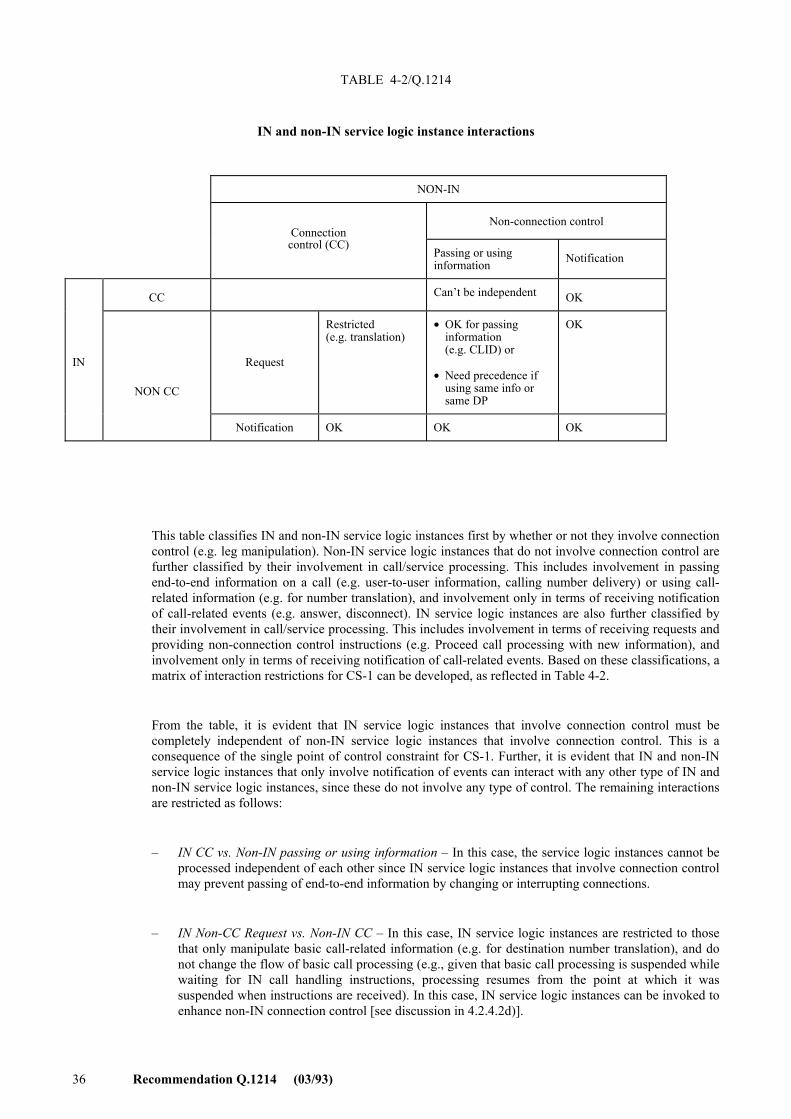
36 Recommendation Q.1214 (03/93)
TABLE 4-2/Q.1214
IN and non-IN service logic instance interactions
This table classifies IN and non-IN service logic instances first by whether or not they involve connection control (e.g. leg manipulation). Non-IN service logic instances that do not involve connection control are further classified by their involvement in call/service processing. This includes involvement in passing end-to-end information on a call (e.g. user-to-user information, calling number delivery) or using call-related information (e.g. for number translation), and involvement only in terms of receiving notification of call-related events (e.g. answer, disconnect). IN service logic instances are also further classified by their involvement in call/service processing. This includes involvement in terms of receiving requests and providing non-connection control instructions (e.g. Proceed call processing with new information), and involvement only in terms of receiving notification of call-related events. Based on these classifications, a matrix of interaction restrictions for CS-1 can be developed, as reflected in Table 4-2.
From the table, it is evident that IN service logic instances that involve connection control must be completely independent of non-IN service logic instances that involve connection control. This is a consequence of the single point of control constraint for CS-1. Further, it is evident that IN and non-IN service logic instances that only involve notification of events can interact with any other type of IN and non-IN service logic instances, since these do not involve any type of control. The remaining interactions are restricted as follows:
� IN CC vs. Non-IN passing or using information � In this case, the service logic instances cannot be processed independent of each other since IN service logic instances that involve connection control may prevent passing of end-to-end information by changing or interrupting connections.
� IN Non-CC Request vs. Non-IN CC � In this case, IN service logic instances are restricted to those that only manipulate basic call-related information (e.g. for destination number translation), and do not change the flow of basic call processing (e.g., given that basic call processing is suspended while waiting for IN call handling instructions, processing resumes from the point at which it was suspended when instructions are received). In this case, IN service logic instances can be invoked to enhance non-IN connection control [see discussion in 4.2.4.2d)].
NON-IN
Connection
Non-connection control
control (CC)
Passing or using information Notification
CC Can�t be independent OK
IN
NON CC
Request
Restricted (e.g. translation)
• OK for passing information (e.g. CLID) or
• Need precedence if using same info or same DP
OK
Notification OK OK OK

Recommendation Q.1214 (03/93) 37
� IN Non-CC Request vs Non-IN passing or using information � In this case, passing end-to-end information should be transparent to IN service logic instances. However, IN and non-IN service logic instances may be competing for the same call-related events or information. Straightforward precedence and exclusion mechanisms can be used to resolve this contention for CS-1. These mechanisms are described in 4.2.4.3.
These restrictions are identified as guidelines to assist implementors in managing these types of interactions in a proprietary manner in those cases where mechanisms are not described in this Recommendation.
d) Applying �Type A� IN technology to �Type B� services
There are some circumstances in which it will be possible to apply �Type A� IN technology to certain aspects of �Type B� services. This applies to switch-based services in general, whether these services be of �Type A� or �Type B�, and to �Type B� services in general, whether these be switch-based or CS-n based.
�Type A� services are characterized as �single-ended� and �single point of control�. It also happens that CS-1 is limited to �single medium� (as opposed to �multi-media�) services. By implication, �Type B� services differ from �Type A� services in at least one of the dimensions: (ends, points of control, media). Of main interest in the shorter term is variation of the number of ends affected. Some examples of �Type A� services are: Freephone, virtual private network (VPN), universal personal telecommunications (UPT), originating and terminating call screening, selective call forward on busy/don�t answer, credit card calling, televoting, malicious call identification, and completion of call to busy subscriber. Currently defined �Type B� services are generally available using switch-based technology. It may be expected that equipment vendors will provide support and interworking of �Type A� and �Type B� services in their product portfolios. Such interworking will not necessarily be part of the standards for CS-1.
i) Situations when �Type A� capabilities may be used with �Type B� or switch-based services
In circumstances where a request for a �Type B� or switch-based service requires a check to see whether such a service may be performed, �Type A� technology may be applied before proceeding with the service.
In circumstances where several variations in a �Type B� or switch-based service are possible, a check to see which variation is to be performed may make use of �Type A� technology.
ii) Determining when to use �Type A� capabilities
In the active phase of a call, certain means for gaining the attention of the exchange (e.g. switch-hook flash) are context specific. In these circumstances, the context needs to be considered first to determine whether a �Type A� service request should occur. For example, after receiving call waiting tone, a series of switch-hook flashes may be used to toggle between the two calls. In the absence of call waiting, a switch-hook flash may indicate a desire to add in a third party, with a subsequent switch-hook flash joining the three subscribers.
From these two cases, it can be seen that some care needs to be taken in determining whether or not it is appropriate to launch a �Type A� service query. In the example described, it would not be appropriate once the call waiting tone has been applied, nor after the waiting call has been answered. In the second case, it would be appropriate to see what should be done. Some options that could be indicated to the switch might be: ignore the switch-hook flash, proceed with normal three party call, add-in fixed third party (e.g. supervisor), etc.
Taking full advantage of this approach will require some extension of the SSF � SCF interface to include identification of the specific service and instruction to proceed or not with (standardized) services. The extent to which this can be standardized for CS-1 will depend on the time and resources available to do it as the standardization for the base capabilities to support �Type A� services proceeds.
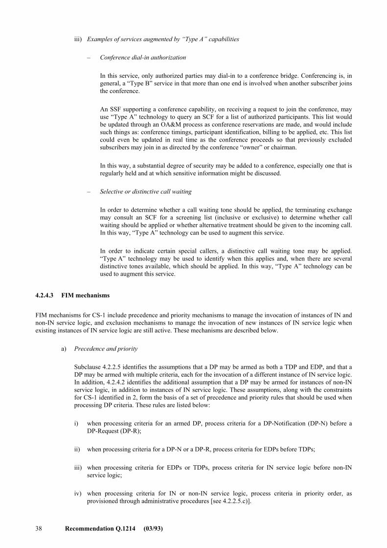
38 Recommendation Q.1214 (03/93)
iii) Examples of services augmented by �Type A� capabilities
� Conference dial-in authorization
In this service, only authorized parties may dial-in to a conference bridge. Conferencing is, in general, a �Type B� service in that more than one end is involved when another subscriber joins the conference.
An SSF supporting a conference capability, on receiving a request to join the conference, may use �Type A� technology to query an SCF for a list of authorized participants. This list would be updated through an OA&M process as conference reservations are made, and would include such things as: conference timings, participant identification, billing to be applied, etc. This list could even be updated in real time as the conference proceeds so that previously excluded subscribers may join in as directed by the conference �owner� or chairman.
In this way, a substantial degree of security may be added to a conference, especially one that is regularly held and at which sensitive information might be discussed.
� Selective or distinctive call waiting
In order to determine whether a call waiting tone should be applied, the terminating exchange may consult an SCF for a screening list (inclusive or exclusive) to determine whether call waiting should be applied or whether alternative treatment should be given to the incoming call. In this way, �Type A� technology can be used to augment this service.
In order to indicate certain special callers, a distinctive call waiting tone may be applied. �Type A� technology may be used to identify when this applies and, when there are several distinctive tones available, which should be applied. In this way, �Type A� technology can be used to augment this service.
4.2.4.3 FIM mechanisms
FIM mechanisms for CS-1 include precedence and priority mechanisms to manage the invocation of instances of IN and non-IN service logic, and exclusion mechanisms to manage the invocation of new instances of IN service logic when existing instances of IN service logic are still active. These mechanisms are described below.
a) Precedence and priority
Subclause 4.2.2.5 identifies the assumptions that a DP may be armed as both a TDP and EDP, and that a DP may be armed with multiple criteria, each for the invocation of a different instance of IN service logic. In addition, 4.2.4.2 identifies the additional assumption that a DP may be armed for instances of non-IN service logic, in addition to instances of IN service logic. These assumptions, along with the constraints for CS-1 identified in 2, form the basis of a set of precedence and priority rules that should be used when processing DP criteria. These rules are listed below:
i) when processing criteria for an armed DP, process criteria for a DP-Notification (DP-N) before a DP-Request (DP-R);
ii) when processing criteria for a DP-N or a DP-R, process criteria for EDPs before TDPs;
iii) when processing criteria for EDPs or TDPs, process criteria for IN service logic before non-IN service logic;
iv) when processing criteria for IN or non-IN service logic, process criteria in priority order, as provisioned through administrative procedures [see 4.2.2.5.c)].
Recommendation Q.1214 (03/93) 39
Application of these rules results in the following precedence ordering, with a priority ordering of multiple service logic instances at each level:
� EDP-N for an instance of IN service logic � A control or monitor relationship exists with an SCF for an existing IN service logic instance; the event detected at the DP is reported to the SCF in the context of the existing relationship and the next DP criteria is processed immediately. No response is expected from the SCF.
� EDP-N for an instance of Non-IN service logic � The EDP is for an existing non-IN service logic instance in the SSF/CCF; the event detected at the DP is reported to the non-IN FM and the next DP criteria is processed immediately. No response is expected from the non-IN FM.
� TDP-N for an instance of IN service logic � The event detected at the DP is reported to the SCF via a new monitor relationship and the next DP criteria is processed immediately. No response is expected from the SCF.
� TDP-N for an instance of Non-IN service logic � The TDP is for a non-IN service logic instance in the SSF/CCF; the event detected at the DP is reported to the non-IN FM and the next DP criteria is processed immediately. No response is expected from the non-IN FM.
� EDP-R for an instance of IN service logic � A control relationship exists with an SCF for an existing IN service logic instance; the event detected at the DP is reported to the SCF in the context of the existing control relationship. Call processing is suspended and a response is expected from the SCF.
� EDP-R for an instance of Non-IN service logic � The EDP is for an existing non-IN service logic instance in the SSF/CCF; the event detected at the DP is reported to the non-IN FM. Call processing is suspended and a response is expected from the non-IN FM.
� TDP-R for an instance of IN service logic � No control relationship exists with an SCF; the event detected at the DP is reported to the SCF via a new control relationship. Call processing is suspended and a response is expected from the SCF.
� TDP-R for an instance of Non-IN service logic � The TDP is for a non-IN service logic instance in the SSF/CCF; the event detected at the DP is reported to the non-IN FM. Call processing is suspended and a response is expected from the non-IN FM.
For those cases in which a response is expected and the response indicates that call processing should continue from the point at which it was suspended (i.e. the DP at which criteria were met and the event was reported), then the remaining DP criteria should be processed. If the response indicates that call processing should continue at a new point in call, then any remaining DP criteria at the point of suspension are not processed.
b) Exclusion
There is no explicit mechanism in CS-1 for managing exclusion of new instances of IN service logic when existing instances of IN service logic are still active. However, there are implicit exclusion mechanisms for CS-1 that have already been described. Subclause 4.2.2.5 describes rules that allow only one IN service logic instance at a time to control the same call segment (i.e. to send responses to the SSF/CCF). These rules exclude multiple IN service logic instances simultaneously controlling the same call segment, but do not exclude multiple IN service logic instances from receiving notification of events detected in a call segment that is being controlled by another IN service logic instance. In addition, subclause 4.2.4.3.a) above describes precedence and priority rules for processing DP criteria for service logic instances. These rules identify that service logic instances at a lower precedence level or priority may not be invoked, depending on the disposition of previous service logic instances. This implies that DP criteria for multiple service logic instances at the same DP can be ordered in such a way as to manage this exclusion.
40 Recommendation Q.1214 (03/93)
4.2.5 Relationship of SSF/CCF model components
Recommendation Q.1214 (03/93)
4.2.5.1 General
Subclause 4.2.1 identifies relationships between the major components of the SSF/CCF model. The major relationships are those between the SCF and the IN-SM (via the SCF Access Function), between the IN-SM and the FIM/CM, and between the FIM/CM and the BCM. The relationship between the SCF and IN-SM is external to the SSF/CCF, and is a subject for standardization. The definition of this relationship follows the methodology described in 3/Q.1201. The other relationships are internal to the SSF/CCF, and are not subjects for standardization. These latter relationships are assumed to exist for explanatory purposes only, to better understand and describe the SSF/CCF model.
All of these relationships are described by the information flows between components. Information flows in the SSF/CCF model are identified in Figure 4-17, which only shows the relationships in half of Figure 4-1. These information flows are described below.
T1136380-91/d20
SCF
IN-switching manager
Basic call manager
Feature interactionsmanager/call manager
Non-INfeature manager
Non-IN eventindication
Non-IN controlrequest
BCM eventindication
IN eventindication
SSF/CCF
SSFinformation
flow
BCM controlrequest
IN controlrequest
FIGURE 4-17/Q.1214SSF/CCF model information flows
SCFinformationflow
FIGURE 4-17/Q.1214...[D20] = 11 CM
a) Relationship between SCF and IN-SM:
� SSF information flow � Information from the IN-SM to the SCF (via the SCF access manager in the SSF) that reports a call/connection processing event, as well as the current state of the call/connection instance in which the event is detected, as identified in 6.
� SCF information flow � Information from the SCF to the IN-SM (via the SCF access manager in the SSF) that requests the manipulation of the state of a call/service instance, invoking the types of functions identified in 6.
Recommendation Q.1214 (03/93) 41
b) Relationship between IN-SM and FIM/CM:
� IN event indication � Information from the FIM/CM to the IN-SM that reports a call processing event, the current state of the call in which the event is detected, and whether the event is to be handled by a new instance of IN service logic or an existing active instance.
� IN control request � Information from the IN-SM to the FIM/CM that indicates call/service processing functions requested by the SCF.
c) Relationship between FIM/CM and BCM:
� BCM event indication � Information from the BCM to the FIM/CM that reports a BCSM event and the current state of the BCSM in which the event is detected.
� BCM control request � Information from the FIM/CM to the BCM that requests the manipulation of one or more BCSMs to influence call/service processing.
d) Relationship between FIM/CM and Non-IN FM:
� Non-IN event indication � Information from the FIM/CM to the non-IN FM.
� Non-IN control request � Information from the non-IN FM to the FIM/CM.
The use of these information flows is illustrated in the following subclause.
4.2.5.2 Typical sequence of model actions
This subclause describes a typical sequence of actions in the SSF/CCF model to illustrate the roles and relationships of the major model components. This illustration is not intended to imply or reflect any specific implementation. This scenario provides an example in which a new instance of an IN-SSM is invoked to provide an IN service feature to a user. At the start of this scenario, no IN service logic instances or non-IN service logic instances are active, and there is no existing relationship between the SCF and SSF/CCF.
1. A user is interacting with the SSF/CCF via the CCAF to request the setup of a call. The BCM creates a BCSM to represent the basic call control functions required to establish and maintain this call for the user.
2. In the course of call setup for the user, an event is detected in the BCSM associated with the user�s call.
3. The BCM processes the event at a DP in the BCSM to determine if the event should be reported (i.e. it determines if the DP is armed and DP criteria are met). If so, it sends a BCSM event indication reporting the event to the FIM/CM, along with the state of the BCSM at the time the event was detected. If the BCM needs instructions on how to proceed, BCSM processing is halted at the DP until instructions are received. If not, the BCM continues normal BCSM processing. Thus, three scenarios are possible:
� the BCM determines that the event should not be reported; BCSM processing continues (e.g. no TDP armed);
� the BCM determines that the event should be reported, but does not need further instructions; BCSM processing continues (e.g. TDP-N armed);
� the BCM determines that the event should be reported, and needs further instructions (e.g. TDP-R armed); BCSM processing is halted and the BCM may continue to detect additional events before receiving instructions (the handling of these additional events is not addressed in this example).
4. The FIM/CM receives and processes the BCM event indication to determine if the event is to be processed by an IN service logic instance or a non-IN service logic instance. It also determines if the event is to be processed by a new instance of a service logic instance or an existing active instance.
5.a Assuming the BCM event is to be processed by a new instance of IN service logic, the FIM/CM sends an IN event indication to the IN-SM reporting the event, the state of the BCSM in which it was detected, and indicating that a new instance of IN service logic is to be invoked. Go to step 6.
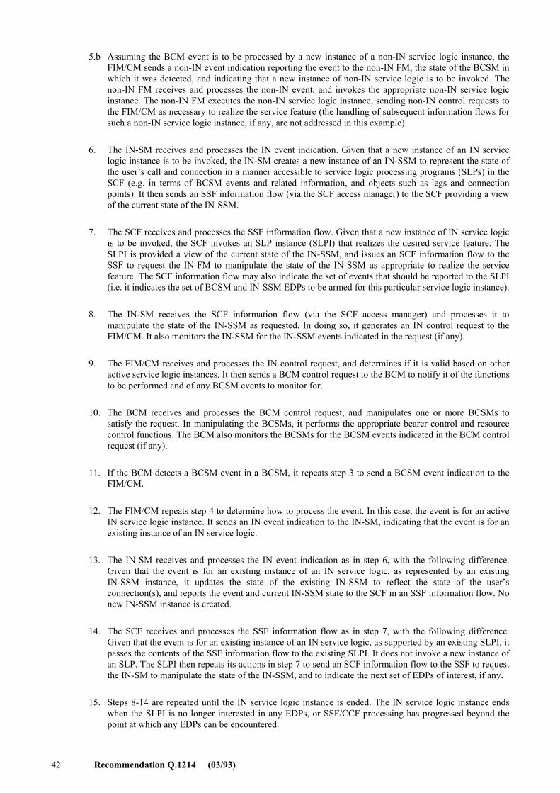
42 Recommendation Q.1214 (03/93)
5.b Assuming the BCM event is to be processed by a new instance of a non-IN service logic instance, the FIM/CM sends a non-IN event indication reporting the event to the non-IN FM, the state of the BCSM in which it was detected, and indicating that a new instance of non-IN service logic is to be invoked. The non-IN FM receives and processes the non-IN event, and invokes the appropriate non-IN service logic instance. The non-IN FM executes the non-IN service logic instance, sending non-IN control requests to the FIM/CM as necessary to realize the service feature (the handling of subsequent information flows for such a non-IN service logic instance, if any, are not addressed in this example).
6. The IN-SM receives and processes the IN event indication. Given that a new instance of an IN service logic instance is to be invoked, the IN-SM creates a new instance of an IN-SSM to represent the state of the user�s call and connection in a manner accessible to service logic processing programs (SLPs) in the SCF (e.g. in terms of BCSM events and related information, and objects such as legs and connection points). It then sends an SSF information flow (via the SCF access manager) to the SCF providing a view of the current state of the IN-SSM.
7. The SCF receives and processes the SSF information flow. Given that a new instance of IN service logic is to be invoked, the SCF invokes an SLP instance (SLPI) that realizes the desired service feature. The SLPI is provided a view of the current state of the IN-SSM, and issues an SCF information flow to the SSF to request the IN-FM to manipulate the state of the IN-SSM as appropriate to realize the service feature. The SCF information flow may also indicate the set of events that should be reported to the SLPI (i.e. it indicates the set of BCSM and IN-SSM EDPs to be armed for this particular service logic instance).
8. The IN-SM receives the SCF information flow (via the SCF access manager) and processes it to manipulate the state of the IN-SSM as requested. In doing so, it generates an IN control request to the FIM/CM. It also monitors the IN-SSM for the IN-SSM events indicated in the request (if any).
9. The FIM/CM receives and processes the IN control request, and determines if it is valid based on other active service logic instances. It then sends a BCM control request to the BCM to notify it of the functions to be performed and of any BCSM events to monitor for.
10. The BCM receives and processes the BCM control request, and manipulates one or more BCSMs to satisfy the request. In manipulating the BCSMs, it performs the appropriate bearer control and resource control functions. The BCM also monitors the BCSMs for the BCSM events indicated in the BCM control request (if any).
11. If the BCM detects a BCSM event in a BCSM, it repeats step 3 to send a BCSM event indication to the FIM/CM.
12. The FIM/CM repeats step 4 to determine how to process the event. In this case, the event is for an active IN service logic instance. It sends an IN event indication to the IN-SM, indicating that the event is for an existing instance of an IN service logic.
13. The IN-SM receives and processes the IN event indication as in step 6, with the following difference. Given that the event is for an existing instance of an IN service logic, as represented by an existing IN-SSM instance, it updates the state of the existing IN-SSM to reflect the state of the user�s connection(s), and reports the event and current IN-SSM state to the SCF in an SSF information flow. No new IN-SSM instance is created.
14. The SCF receives and processes the SSF information flow as in step 7, with the following difference. Given that the event is for an existing instance of an IN service logic, as supported by an existing SLPI, it passes the contents of the SSF information flow to the existing SLPI. It does not invoke a new instance of an SLP. The SLPI then repeats its actions in step 7 to send an SCF information flow to the SSF to request the IN-SM to manipulate the state of the IN-SSM, and to indicate the next set of EDPs of interest, if any.
15. Steps 8-14 are repeated until the IN service logic instance is ended. The IN service logic instance ends when the SLPI is no longer interested in any EDPs, or SSF/CCF processing has progressed beyond the point at which any EDPs can be encountered.
Recommendation Q.1214 (03/93) 43
4.2.6 Relationship of SSF/CCF to SCF
This subclause only addresses call associated relationships as supported by a CS-1 connection control IN-SSM.
a) An SSF/CCF can have call associated relationships with multiple SCFs, and an SCF can have call associated relationships with multiple SSF/CCFs. Each relationship is treated as a one-to-one relationship.
b) When the SSF/CCF initiates a relationship, it reports the state of the IN-SSM in which the TDP was detected. The state information that is included in the information flows between the SSF/CCF and the SCF is defined by the information elements included in the information flows, based on the analysis of CS-1 SIBs and detailed DFP modelling.
c) Once a control relationship is established between the SSF/CCF and the SCF, the SCF can request the SSF/CCF to monitor for and report subsequent events (i.e. arm EDPs), as well as to stop monitoring (i.e. disarm EDPs).
Annex B addresses the nature of the relationship between the SSF/CCF and the SCF. It describes general terminology and possible control and monitor scenarios for both normal and abnormal situations.
4.3 Specialized resource function (SRF) model
4.3.1 General
A model of the SRF is shown in Figure 4-18. The purpose of this model is to provide a framework for specialized resource functionality subjects with respect to the SRF.
SRF provides various specialized resources as shown in 4.3.4. The SRF is managed to place resources in or out of service, e.g. for provisioning, administration and maintenance purpose. The SRF management by the SMF is, however, for further study. But in any case, it is activated by a request from another functional entity, and never takes action by itself.
For call/service processing, the SRF has a logical relationship with the SSF/CCF and the SCF. The SCF controls the connection between the SSF/CCF and the SRF, and sends instructions to the SRF.
As part of the process of formulating a response to the SSF, the SCF may need to enter into a dialogue with a calling or a called party. This could, for example, take the form of a prompt and collect digits sequence.
The SCF in CS-1 will instruct the SRF to start a dialogue with a user after setting up a path between the SSF/CCF and the SRF. The dialogue between the SRF and the user allows the SRF to play an announcement and if appropriate, collect digits. If digits have been collected, the SRF will pass the digit information to the SCF.
A user, being prompted from the SRF, inputs MF tones, for example, to the SRF so that the collected digits can be reported to the SCF. When the service logic in the SCF does not need the resources anymore, the SCF requests the SSF/CCF to release the connection with the SRF and the resource in the SRF will be released.
4.3.2 SRF components
To provide the functionality defined in the previous subclause, the SRF includes the following functions as illustrated in Figure 4-18.
Functional entity access manager (FEAM)
The FEAM provides the functionality necessary for the SRF to exchange information with other functional entities via messages as follows:
� provide reliable message transfer;
� ensure sequential message delivery;
� allow message request/response pairs to be correlated;
� allow multiple messages to be associated with each other; and
� comply with OSI structures and principles.
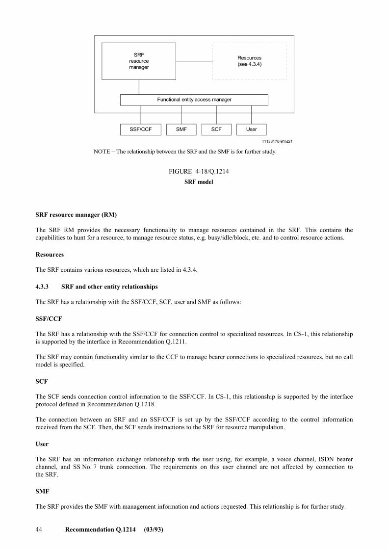
44 Recommendation Q.1214 (03/93)
T1133170-91/d21
SRFresourcemanager
Resources(see 4.3.4)
Functional entity access manager
SSF/CCF SMF SCF User
FIGURE 4-18/Q.1214SRF model
NOTE � The relationship between the SRF and the SMF is for further study.
FIGURE 4-18/Q.1214...[D021] = 8 CM
SRF resource manager (RM)
The SRF RM provides the necessary functionality to manage resources contained in the SRF. This contains the capabilities to hunt for a resource, to manage resource status, e.g. busy/idle/block, etc. and to control resource actions.
Resources
The SRF contains various resources, which are listed in 4.3.4.
4.3.3 SRF and other entity relationships
The SRF has a relationship with the SSF/CCF, SCF, user and SMF as follows:
SSF/CCF
The SRF has a relationship with the SSF/CCF for connection control to specialized resources. In CS-1, this relationship is supported by the interface in Recommendation Q.1211.
The SRF may contain functionality similar to the CCF to manage bearer connections to specialized resources, but no call model is specified.
SCF
The SCF sends connection control information to the SSF/CCF. In CS-1, this relationship is supported by the interface protocol defined in Recommendation Q.1218.
The connection between an SRF and an SSF/CCF is set up by the SSF/CCF according to the control information received from the SCF. Then, the SCF sends instructions to the SRF for resource manipulation.
User
The SRF has an information exchange relationship with the user using, for example, a voice channel, ISDN bearer channel, and SS No. 7 trunk connection. The requirements on this user channel are not affected by connection to the SRF.
SMF
The SRF provides the SMF with management information and actions requested. This relationship is for further study.
Recommendation Q.1214 (03/93) 45
4.3.4 Objects of SRF management
Examples of specialized resources managed by the SRF are as follows:
� DTMF receiver.
� Tone generator.
� Announcements.
� Message sender/receiver.
� Synthesized voice/speech recognition devices with interactive prompting facilities.
� Text to speech synthesis.
� Protocol converters.
� Audio conference bridge.
� Information distribution bridge.
The following four objects are supported in CS-1 and defined as follows:
1) DTMF receiver
This resource receives dual tone multi-frequency (DTMF) from a linked resource, and recognizes it as a standardized signal input.
2) Tone generator/announcements
This resource provides in-channel information to the specified virtual resource.
3) Message sender/receiver
This resource sends or receives messages, such as electronic messages, voice messages, etc., to/from users.
4) Synthesized voice/speech recognition device with interactive prompting facilities
This resource receives in-channel speech information from a linked virtual resource, and recognizes it as a standardized signal input. When the information is input from a user, it is recognized by this resource and this resource converts it to IN perceivable signals. When this resource receives an instruction to send a voice message with source-information, it is converted to voice message. Usually, such action is performed with interactive prompting.
The following four objects are for further study:
5) Audio conference bridge
Receiving in-channel audio information from any other linked virtual resources, this resource mixes this information and sends the mixed information to all the linked virtual resources. Another new virtual resource can be joined to or any virtual resources linked to it can be split from this connection resource. It is used as an audio conference bridge.
6) Information distribution bridge
Receiving in-channel information from a linked virtual resource, this resource distributes the information to all the other linked virtual resources. Another new virtual resource can be joined to or any virtual resources which receive distributed information can be split from the connection resource. It is used as a broadcasting device.
7) Text to speech synthesis
8) Protocol converters
4.4 Service control function (SCF) model
4.4.1 General
A model of the SCF is shown in Figure 4-19. The purpose of this model is to provide a framework for service logic processing subjects with respects to the SCF.
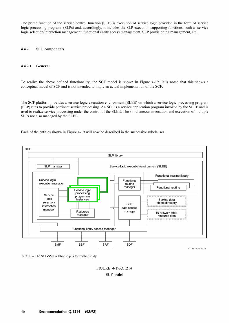
46 Recommendation Q.1214 (03/93)
The prime function of the service control function (SCF) is execution of service logic provided in the form of service logic processing programs (SLPs) and, accordingly, it includes the SLP execution supporting functions, such as service logic selection/interaction management, functional entity access management, SLP provisioning management, etc.
4.4.2 SCF components
4.4.2.1 General
To realize the above defined functionality, the SCF model is shown in Figure 4-19. It is noted that this shows a conceptual model of SCF and is not intended to imply an actual implementation of the SCF.
The SCF platform provides a service logic execution environment (SLEE) on which a service logic processing program (SLP) runs to provide pertinent service processing. An SLP is a service application program invoked by the SLEE and is used to realize service processing under the control of the SLEE. The simultaneous invocation and execution of multiple SLPs are also managed by the SLEE.
Each of the entities shown in Figure 4-19 will now be described in the successive subclauses.
T1133180-91/d22
SLP library
SCF
SLP manager Service logic execution environment (SLEE)
Servicelogic
selection/interactionmanager
Service logicprocessingprogrammeinstances
Resourcemanager
Service logicexecution manager
Functionalroutine
manager
SCFdata access
manager
Functional routine library
Functional routine
Service dataobject directory
IN network-wideresource data
Functional entity access manager
SMF SSF SRF SDF
NOTE � The SCF-SMF relationship is for further study.
FIGURE 4-19/Q.1214SCF model
FIGURE 4-19/Q.1214...[D22] = 12 CM
Recommendation Q.1214 (03/93) 47
4.4.2.2 Service logic execution manager (SLEM)
4.4.2.2.1 General
The SLEM is the functionality that handles and controls the total service logic execution action. The SLEM contains service logic processing program instances (SLPIs), service logic selection/interaction manager, and resource manager. It also interacts with SCF data access manager and functional entity access manager to support SLPI execution. In addition to these aspects, the SLEM needs functionality to:
� execute SLPIs and maintain transient data associated with SLPIs (i.e. information that only persists during the lifetime of the SLPI, such as SLPI state information);
� execute functional routines in support of SLPI execution;
� manage SLPI access to SCF and SDF data via the SCF data access manager (see 4.4.2.3);
� manage the exchange of information between SLPIs and entities in other functional entities via the functional entity access manager (see 4.4.2.5).
4.4.2.2.2 Service logic selection/interaction manager (SLSIM)
The SLSIM is the entity that selects an SLP for execution and controls the simultaneous execution and/or execution order of multiple SLPs in the same SCF. It is for further study whether or not the SLSIM is explicitly divided into two different entities, i.e. the service logic selection manager and the service logic interaction manager.
As part of the functionality, the SLSIM provides a means to manage service interactions by managing interactions among multiple SLPIs in the same SCF that are simultaneously active on a single call. The relationship between SLSIM and the feature interaction manager/call manager in the SSF/CCF is for further study.
SLP selection is performed via the SLSIM in response to:
� an external event from another functional entity;
� the occurrence of internally recognized conditions (e.g. time of day or other internal events); and
� the execution of a functional routine via an SLPI that requests the execution of another SLP.
In addition, the SLSIM should invoke the execution of the selected SLP and provide for mutual exclusion and precedence during this SLP selection and invocation:
� mutual exclusion prevents the invocation of an SLP whose execution would be incompatible with a currently executing SLPI;
� precedence provides a scheme to select a particular SLP from a set of SLPs which meet the same selection criteria.
4.4.2.2.3 Service logic processing program instance (SLPI)
A service logic processing program (SLP) is a service application program invoked by the SLEE and used to realize service processing. It contains logical constructs which, when executed, control the flow of service execution, and statements that, when executed, invoke functional routines in the SCF to access network resources and data needed for service execution. When an SLP is selected and invoked, it is referred to as a service logic processing program instance (SLPI). In contrast to an SLP, a corresponding SLPI is a dynamic entity that actively controls the flow of service execution and invokes SCF functional routines.
Functional routines are the functionality in the SCF that can be invoked by SLPIs to cause a sequence of functional entity actions to be performed in the network in support of service execution. This sequence of functional entity actions provides the functionality defined for a service independent building block (SIB) on the global functional plane. Therefore, functional routines are considered to be service independent. Potential categories of functional routines are described in 4.4.3.
48 Recommendation Q.1214 (03/93)
4.4.2.2.4 Resource manager
The resource manager provides the functionality to control the allocation of local SCF resources and provides access to network resources in support of SLPI execution. The resource manager contains functionality to:
� identify and locate local SCF resources;
� identify and locate network resources via the SCF data access manager and IN network-wide resource data (see 4.4.2.3.3);
� identify one or more local SCF resources requested by a particular SLPI;
� release one or more local SCF resources no longer needed by a particular SLPI; and
� interact with other functional entities via the functional entity access manager to provide for the reservation and release of network resources to be used by SLPIs.
It is noted that SRF selection is not always performed by the SLEM resource manager, in some cases, selection is performed by an SSF, for example, upon assist/hand-off procedure being used.
4.4.2.3 SCF data access manager
4.4.2.3.1 General
The SCF data access manager provides the functionality needed to provide for the storage, management, and access of shared and persistent information in the SCF (i.e. information that persists beyond the lifetime of a SLPI). The SCF data access manager also provides the functionality needed to access remote information in SDFs. The SCF data access manager interacts with the SLEM to provide these functionalities to SLPIs.
Figure 4-19 identifies two structures that contain SCF data. These include:
� the service data object directory; and
� the IN network-wide resource data.
These are described in the following subclauses.
4.4.2.3.2 Service data object directory
Figure 4-19 identifies a service data object directory. It provides a means to address the appropriate SCF for access to a specific data object.
The SLEM interacts with the SCF data access manager to access service data objects in SDFs. The SDF data access manager uses the service data object directory to locate service data objects in the network in a manner transparent to the SLEM (and its SLPI). As such, the SLEM (and its SLPIs) has a global and uniform view of service data objects in the network.
4.4.2.3.3 IN network-wide resource data
This is a structure in which information resides about the location and capabilities of resources in the network accessible to SLPIs. It provides a means to address the appropriate functional entity (e.g. SRF) for access to specific resources with the appropriate capabilities.
The SLEM resource manager interacts with the SCF data access manager to access network resource data. The SLEM resource manager provides SLPIs with access to network resources in a manner transparent to SLPIs. As such, SLPIs have a global and uniform view of resources in the network.
4.4.2.4 Functional routine manager
Functional routine manager will be used for reception and distribution of functional routines to functional routine library via functional entity access manager. This entity also manages the addition, deletion and suspension of a particular functional routine. Such management of functional routines by the SMF is for further study.
Functional routine library is an entity where the actual functional routines are residing.
Recommendation Q.1214 (03/93) 49
4.4.2.5 Functional entity access manager (FEAM)
The functional entity access manager provides the functionality needed by the SLEM to exchange information with other functional entities via messages. This message handling functionality should
� be transparent to SLPIs;
� provide reliable message transfer;
� ensure sequential message delivery;
� allow message request/response pairs to be correlated;
� allow multiple messages to be associated with each other; and
� comply with OSI structures and principles.
4.4.2.6 SLP manager
The SLP manager manages the reception and distribution function of SLPs from other entities. The SLP manager, therefore, interworks with functional entity access manager (FEAM). This entity also manages addition, deletion and suspension of a particular SLP. Such management of the SLP by the SMF is for further study.
4.4.3 Functional routine categories
The following categories of functional routines are proposed as framework for describing the SCF functionality accessible to SLPIs:
SLPI management functional routines
� functional routines to facilitate SLPI initialization and termination;
� functional routines to invoke other SLPs.
SLPI communication functional routines
� functional routines to support communication between SLPIs.
Timer management functional routines
� functional routines to retrieve the current time and date;
� functional routines to manage asynchronous timers in the SCF;
� functional routines to block the invocation of an SLP for a certain defined period.
Data management interface functional routines
� functional routines to access and manipulate SCF data (i.e. service data object directory and IN network-wide resource data) and network data (i.e. in an SDF) globally and uniformly via the SCF data access manager.
Asynchronous event handling functional routines
� functional routines to perform appropriate functions in response to asynchronous events (e.g. events reported by other functional entities, SLPI execution error events, and internal SCF events);
� functional routines to facilitate termination of a service execution and initialization of related resources.
Connection management functional routines
� functional routines to manipulate legs and connection points via interaction with the IN-feature manager in the SSF.
Specialized resource management functional routines
� functional routines to access and use specialized network resources globally and uniformly via the SLEM resource manager (interacting with the SRF).
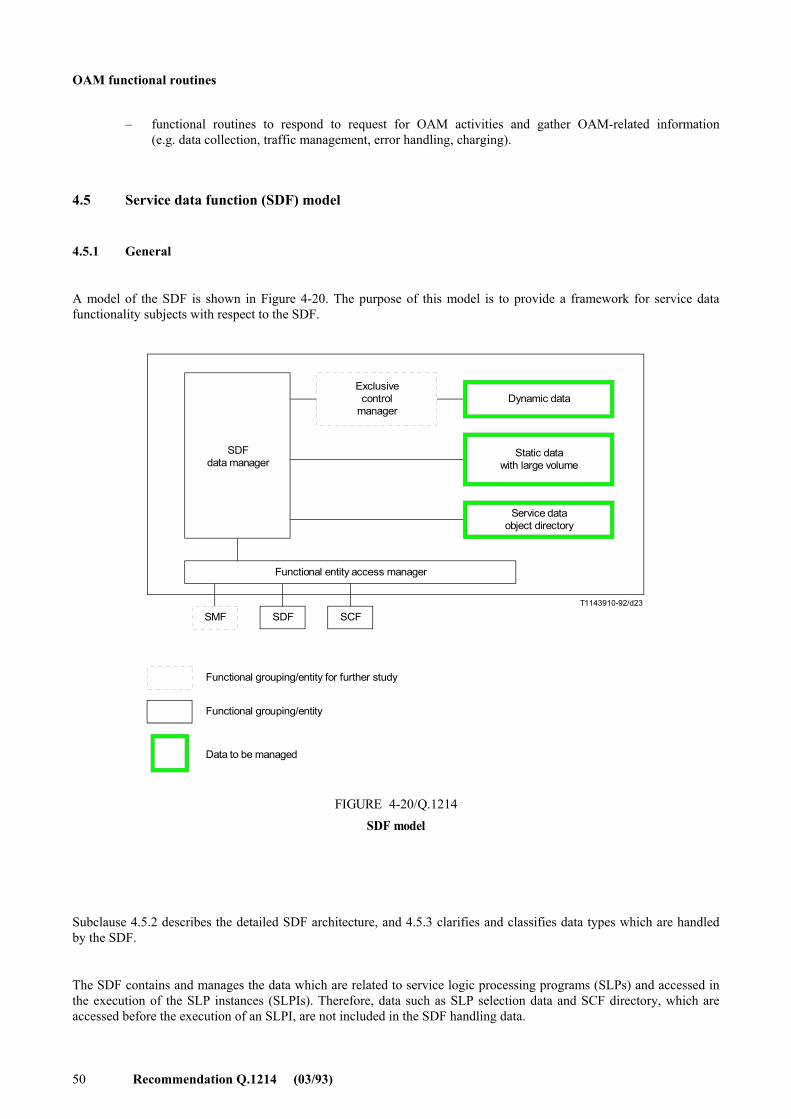
50 Recommendation Q.1214 (03/93)
OAM functional routines
� functional routines to respond to request for OAM activities and gather OAM-related information (e.g. data collection, traffic management, error handling, charging).
4.5 Service data function (SDF) model
4.5.1 General
A model of the SDF is shown in Figure 4-20. The purpose of this model is to provide a framework for service data functionality subjects with respect to the SDF.
T1143910-92/d23
SDFdata manager
Exclusivecontrol
managerDynamic data
Static datawith large volume
Service dataobject directory
Functional entity access manager
SMF SDF SCF
Functional grouping/entity for further study
Functional grouping/entity
Data to be managed
FIGURE 4-20/Q.1214SDF model
FIGURE 4-20/Q.1214...[D23] = 12.5 CM
Subclause 4.5.2 describes the detailed SDF architecture, and 4.5.3 clarifies and classifies data types which are handled by the SDF.
The SDF contains and manages the data which are related to service logic processing programs (SLPs) and accessed in the execution of the SLP instances (SLPIs). Therefore, data such as SLP selection data and SCF directory, which are accessed before the execution of an SLPI, are not included in the SDF handling data.
Recommendation Q.1214 (03/93) 51
4.5.2 SDF components
4.5.2.1 General
To realize the above defined functionality, the recommended SDF model is shown in Figure 4-20. Each of the functional entities shown in Figure 4-20 will be described in the successive subclauses. This is not meant to imply any specific implementation.
4.5.2.2 SDF data manager
The SDF data manager provides the functionality needed for storing, managing and accessing information in the SDF. If, for example, the data are physically structured as a data base, the SDF data manager may also handle data base accessing language such as an SQL.
4.5.2.3 Functional entity access manager
The functional entity access manager provides the functionality needed by the SDF data manager to exchange information with other functional entities, i.e. SCF, SDF and SMF, via messages. This message handling functionality should
� provide reliable message transfer;
� ensure sequential message delivery;
� allow message request/response pairs to be correlated;
� allow multiple messages to be associated with each other; and
� comply with OSI structures and principles.
Here, the functional entity access manager may access other SDFs, because the data distribution in the network can completely be transparent to the SCF. However, this point as well as the functional relationship with the SMF is outside the scope of CS-1.
4.5.2.4 Exclusive control manager
The exclusive control manager provides the functionality needed to provide exclusive control, for example lock-unlock control, to ensure data integrity. However, this functional grouping/entity and its action method, such as whether the exclusive control is always necessary or is necessary for some methods of data access, are for further study.
4.5.3 Data types handled by SDF
The data which are handled by the SDF can be classified into the following types.
While Recommendation Q.1290 defines the terms �static� and �dynamic� in terms of call processing concepts, here these terms are defined for specific purposes of the DFP as follows:
a) The data that are �read-only� as far as SLPs are concerned are called static.
b) The data that can be changed by SLPs are called dynamic.
These types of data are further subdivided as follows:
1) Type 1 data � These are dynamic data that are local to an SLPI, e.g. call instance data parameters like the dialled number.
2) Type 2 data � These are static data that are feature-specific and are shared by SLPIs, e.g. subscription data parameters like day of week or time of day screening.
3) Type 3 data � These are dynamic data that are feature-specific and are shared by SLPIs, e.g. sum of charging or a counter for a call number limiting service.
Here, it is assumed that an SLP includes type 1 data. Other than the above data, there can exist the following data types which may commonly be accessed among SLPIs for multiple service features.
4) Type 4 data � These are static data that belong to multiple service features and are shared by SLPIs, e.g. a subscriber�s phone number list to connect.
52 Recommendation Q.1214 (03/93)
5) Type 5 data � These are dynamic data that belong to multiple service features and are shared by SLPIs, e.g. subscriber�s location data used by a service such as UPT.
Besides the locally available service data objects, additional data is used to locate service data objects in other SDFs in the network. The additional data is used in a manner which is transparent to the SLEM (and its SLPI) in the SCF requesting the locally unavailable data.
6) Type 6 data � Service data object directory.
Upon a data object retrieval request by the SCF, the SDF data manager will try to locate the data object locally. When the requested data object is not available, it will try to retrieve a reference to another SDF from the SDOD. If a reference is available, the SDF will either refer this back to the requesting SCF, or try to retrieve the requested data directly from the referenced SDF. However, the latter mechanism is outside the scope of CS-1. If a reference is not available, the SDF data manager will return a failure to the requesting SCF.
Figure 4-21 illustrates the image of each data type.
5 Stage 2 descriptions of service independent building blocks (SIBs)
This clause provides stage 2 descriptions for service independent building blocks (SIBs) for the intelligent network that are used in executing supplemented services. The functional entities involved, information flows and functional entity actions required to provide the SIBs are defined. Each SIB, along with other SIBs, can be used and reused as an element of various supplemented services. While SIBs are defined in the global functional plane, their interface requirements may be seen in the distributed functional plane of the intelligent network conceptual model.
5.1 Introduction
An intelligent network has two realms related to call/service processing:
1) basic call processing (network functions that provide basic bearer services); and
2) service control (functions that add service elements to basic calls by modifying and/or otherwise controlling call processing functions, thus creating supplemented services).
Basic call processing functions are defined in ISDN Recommendation Q.71 wherein basic bearer service call setup and release are depicted. The functional entities involved are the call control agent function (CCAF) and the call control function (CCF).
Service control resides in the service control functional (SCF) entity and it interacts with basic call processing via a service switching functional (SSF) entity associated with the CCF. The responsibilities of the SSF include management of communications with the SCF, adding logic to the CCF to allow it to recognize when bids for IN service control should be initiated, and reacting to instructions or information from service control in order to execute supplemented services.
5.1.1 Functional model
Figure 5-1 depicts the functional entities and their relationships that are used in describing SIBs in the distributed functional plane of the intelligent network. It also shows the relationship of service control to basic call processing functional entities.
5.1.2 Description of functional entities
Functional entities are described in 2.
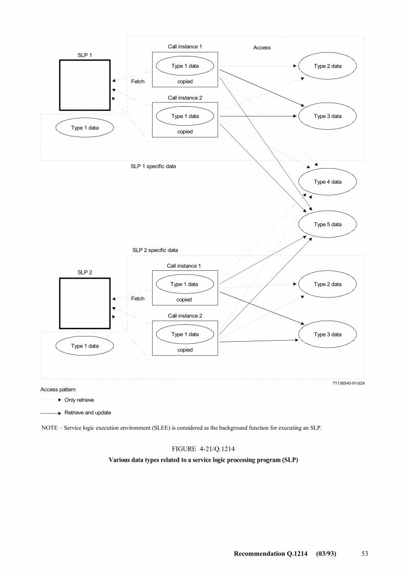
Recommendation Q.1214 (03/93) 53
T1136540-91/d24
SLP 1
Type 1 data
Type 1 data
Call instance 1
copied
Type 2 data
Type 3 data
Type 4 data
Type 5 data
Type 2 data
Type 3 data
Type 1 data
Access
Fetch
SLP 1 specific data
SLP 2
Fetch
Access pattern
Only retrieve
Retrieve and update
NOTE � Service logic execution environment (SLEE) is considered as the background function for executing an SLP.
FIGURE 4-21/Q.1214Various data types related to a service logic processing program (SLP)
Type 1 data
Call instance 2
copied
Type 1 data
Call instance 1
copied
Type 1 data
Call instance 2
copied
SLP 2 specific data
FIGURE 4-21/Q.1214...[D24] = 21 CM PAGE PLEINE
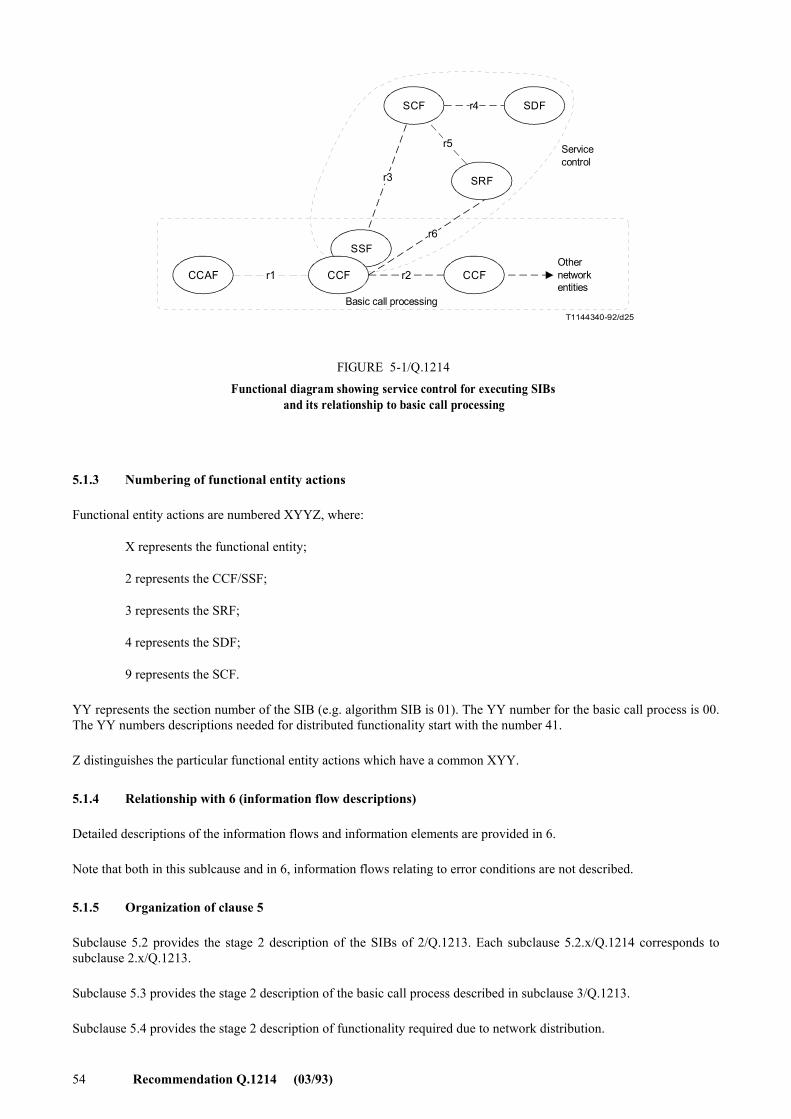
54 Recommendation Q.1214 (03/93)
T1144340-92/d25
CCAF
SSF
CCF CCF
SRF
SCF SDF
r1 r2
r3
r4
r5
r6
Servicecontrol
Othernetworkentities
Basic call processing
FIGURE 5-1/Q.1214
Functional diagram showing service control for executing SIBsand its relationship to basic call processing
FIGURE 5-1/Q.1214...[D25] = 9.5 CM
5.1.3 Numbering of functional entity actions
Functional entity actions are numbered XYYZ, where:
X represents the functional entity;
2 represents the CCF/SSF;
3 represents the SRF;
4 represents the SDF;
9 represents the SCF.
YY represents the section number of the SIB (e.g. algorithm SIB is 01). The YY number for the basic call process is 00. The YY numbers descriptions needed for distributed functionality start with the number 41.
Z distinguishes the particular functional entity actions which have a common XYY.
5.1.4 Relationship with 6 (information flow descriptions)
Detailed descriptions of the information flows and information elements are provided in 6.
Note that both in this sublcause and in 6, information flows relating to error conditions are not described.
5.1.5 Organization of clause 5
Subclause 5.2 provides the stage 2 description of the SIBs of 2/Q.1213. Each subclause 5.2.x/Q.1214 corresponds to subclause 2.x/Q.1213.
Subclause 5.3 provides the stage 2 description of the basic call process described in subclause 3/Q.1213.
Subclause 5.4 provides the stage 2 description of functionality required due to network distribution.
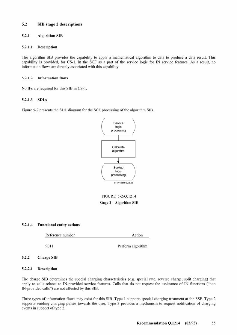
Recommendation Q.1214 (03/93) 55
5.2 SIB stage 2 descriptions
5.2.1 Algorithm SIB
5.2.1.1 Description
The algorithm SIB provides the capability to apply a mathematical algorithm to data to produce a data result. This capability is provided, for CS-1, in the SCF as a part of the service logic for IN service features. As a result, no information flows are directly associated with this capability.
5.2.1.2 Information flows
No IFs are required for this SIB in CS-1.
5.2.1.3 SDLs
Figure 5-2 presents the SDL diagram for the SCF processing of the algorithm SIB.
T1144350-92/d26
Servicelogic
processing
Calculatealgorithm
FIGURE 5-2/Q.1214Stage 2 � Algorithm SIB
Servicelogic
processing
FIGURE 5-2/Q.1214...[D26] = 7 CM
5.2.1.4 Functional entity actions
Reference number Action
9011 Perform algorithm
5.2.2 Charge SIB
5.2.2.1 Description
The charge SIB determines the special charging characteristics (e.g. special rate, reverse charge, split charging) that apply to calls related to IN-provided service features. Calls that do not request the assistance of IN functions (�non IN-provided calls�) are not affected by this SIB.
Three types of information flows may exist for this SIB. Type 1 supports special charging treatment at the SSF. Type 2 supports sending charging pulses towards the user. Type 3 provides a mechanism to request notification of charging events in support of type 2.
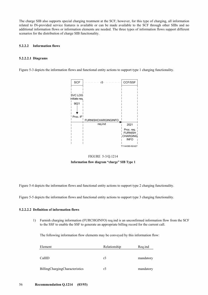
56 Recommendation Q.1214 (03/93)
The charge SIB also supports special charging treatment at the SCF; however, for this type of charging, all information related to IN-provided service features is available or can be made available to the SCF through other SIBs and no additional information flows or information elements are needed. The three types of information flows support different scenarios for the distribution of charge SIB functionality.
5.2.2.2 Information flows
5.2.2.2.1 Diagrams
Figure 5-3 depicts the information flows and functional entity actions to support type 1 charging functionality.
T1144360-92/d27
SCF CCF/SSFr3
Proc. IFFURNISHCHARGINGINFO
req.ind 2021
Proc. req.FURNISH
CHARGINGINFO
FIGURE 5-3/Q.1214Information flow diagram �charge� SIB Type 1
SVC LOGinitiate req.
9021
FIGURE 5-3/Q.1214...[D27] = 9 CM
Figure 5-4 depicts the information flows and functional entity actions to support type 2 charging functionality.
Figure 5-5 depicts the information flows and functional entity actions to support type 3 charging functionality.
5.2.2.2.2 Definition of information flows
1) Furnish charging information (FURCHGINFO) req.ind is an unconfirmed information flow from the SCF to the SSF to enable the SSF to generate an appropriate billing record for the current call.
The following information flow elements may be conveyed by this information flow:
Element Relationship Req.ind
CallID r3 mandatory
BillingChargingCharacteristics r3 mandatory
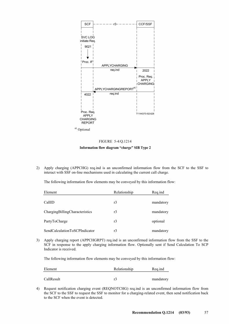
Recommendation Q.1214 (03/93) 57
T1144370-92/d28
SCF CCF/SSFr3
Proc. IFAPPLYCHARGING
req.ind 2022
FIGURE 5-4/Q.1214
Information flow diagram �charge� SIB Type 2
9021
APPLYCHARGINGREPORTreq.ind
Proc. Req.APPLY
CHARGING
4022
Proc. Req.APPLY
CHARGINGREPORT
a)
Optionala)
SVC LOGinitiate Req.
FIGURE 5-4/Q.1214...[D28] = 12 CM
2) Apply charging (APPCHG) req.ind is an unconfirmed information flow from the SCF to the SSF to interact with SSF on-line mechanisms used in calculating the current call charge.
The following information flow elements may be conveyed by this information flow:
Element Relationship Req.ind
CallID r3 mandatory
ChargingBillingCharacteristics r3 mandatory
PartyToCharge r3 optional
SendCalculationToSCPIndicator r3 mandatory
3) Apply charging report (APPCHGRPT) req.ind is an unconfirmed information flow from the SSF to the SCF in response to the apply charging information flow. Optionally sent if Send Calculation To SCP Indicator is received.
The following information flow elements may be conveyed by this information flow:
Element Relationship Req.ind
CallResult r3 mandatory
4) Request notification charging event (REQNOTCHG) req.ind is an unconfirmed information flow from the SCF to the SSF to request the SSF to monitor for a charging-related event, then send notification back to the SCF when the event is detected.
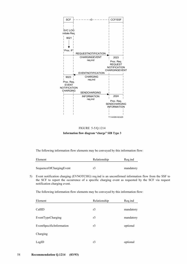
58 Recommendation Q.1214 (03/93)
T1144380-92/d29
SCF CCF/SSFr3
REQUESTNOTIFICATIONCHARGINGEVENT
req.ind2023
EVENTNOTIFICATIONCHARGING
req.ind
Proc. Req.REQUEST
NOTIFICATIONCHARGINGEVENT
9023
Proc. Req.EVENT
NOTIFICATIONCHARGING
SENDCHARGINGINFORMATION
req.ind2024
Proc. Req.SENDCHARGING
INFORMATION
Proc. IF
FIGURE 5-5/Q.1214Information flow diagram �charge� SIB Type 3
9021
SVC LOGinitiate Req.
FIGURE 5-5/Q.1214...[D29] = 13.5 CM
The following information flow elements may be conveyed by this information flow:
Element Relationship Req.ind
SequenceOfChargingEvent r3 mandatory
5) Event notification charging (EVNOTCHG) req.ind is an unconfirmed information flow from the SSF to the SCF to report the occurrence of a specific charging event as requested by the SCF via request notification charging event.
The following information flow elements may be conveyed by this information flow:
Element Relationship Req.ind
CallID r3 mandatory
EventTypeCharging r3 mandatory
EventSpecificInformation r3 optional
Charging
LegID r3 optional
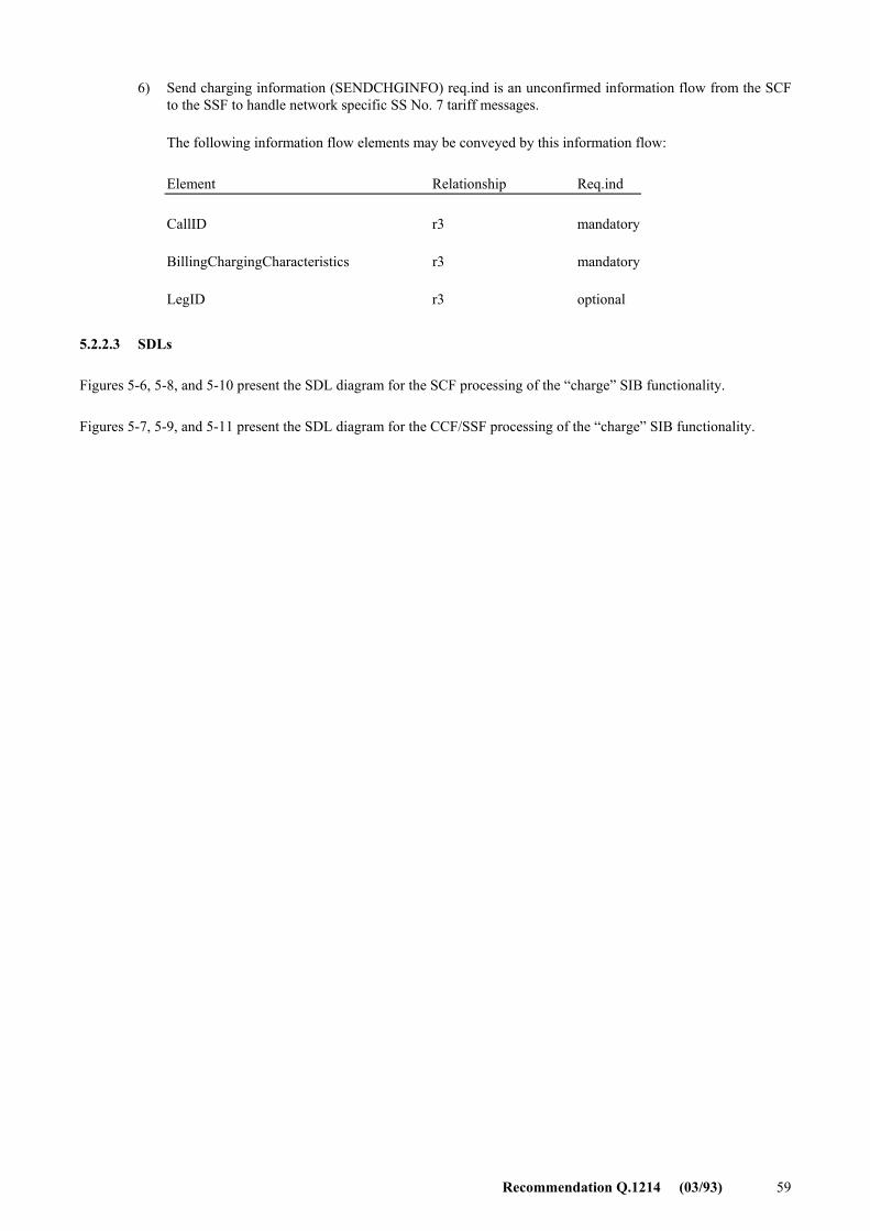
Recommendation Q.1214 (03/93) 59
6) Send charging information (SENDCHGINFO) req.ind is an unconfirmed information flow from the SCF to the SSF to handle network specific SS No. 7 tariff messages.
The following information flow elements may be conveyed by this information flow:
Element Relationship Req.ind
CallID r3 mandatory
BillingChargingCharacteristics r3 mandatory
LegID r3 optional
5.2.2.3 SDLs
Figures 5-6, 5-8, and 5-10 present the SDL diagram for the SCF processing of the �charge� SIB functionality.
Figures 5-7, 5-9, and 5-11 present the SDL diagram for the CCF/SSF processing of the �charge� SIB functionality.
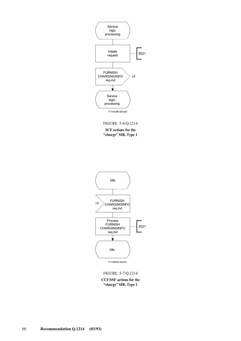
60 Recommendation Q.1214 (03/93)
T1144390-92/d30
9021
r3
Servicelogic
processing
Initiaterequest
FURNISHCHARGINGINFO
req.ind
FIGURE 5-6/Q.1214SCF actions for the
�charge� SIB, Type 1
Servicelogic
processing
FIGURE 5-6/Q.1214...[D30] = 10 CM
T1144400-92/d31
2021
r3
Idle
FIGURE 5-7/Q.1214CCF/SSF actions for the
�charge� SIB, Type 1
Idle
FURNISHCHARGINGINFO
req.ind
ProcessFURNISH
CHARGINGINFOreq.ind
FIGURE 5-7/Q.1214...[D31] = 10 CM
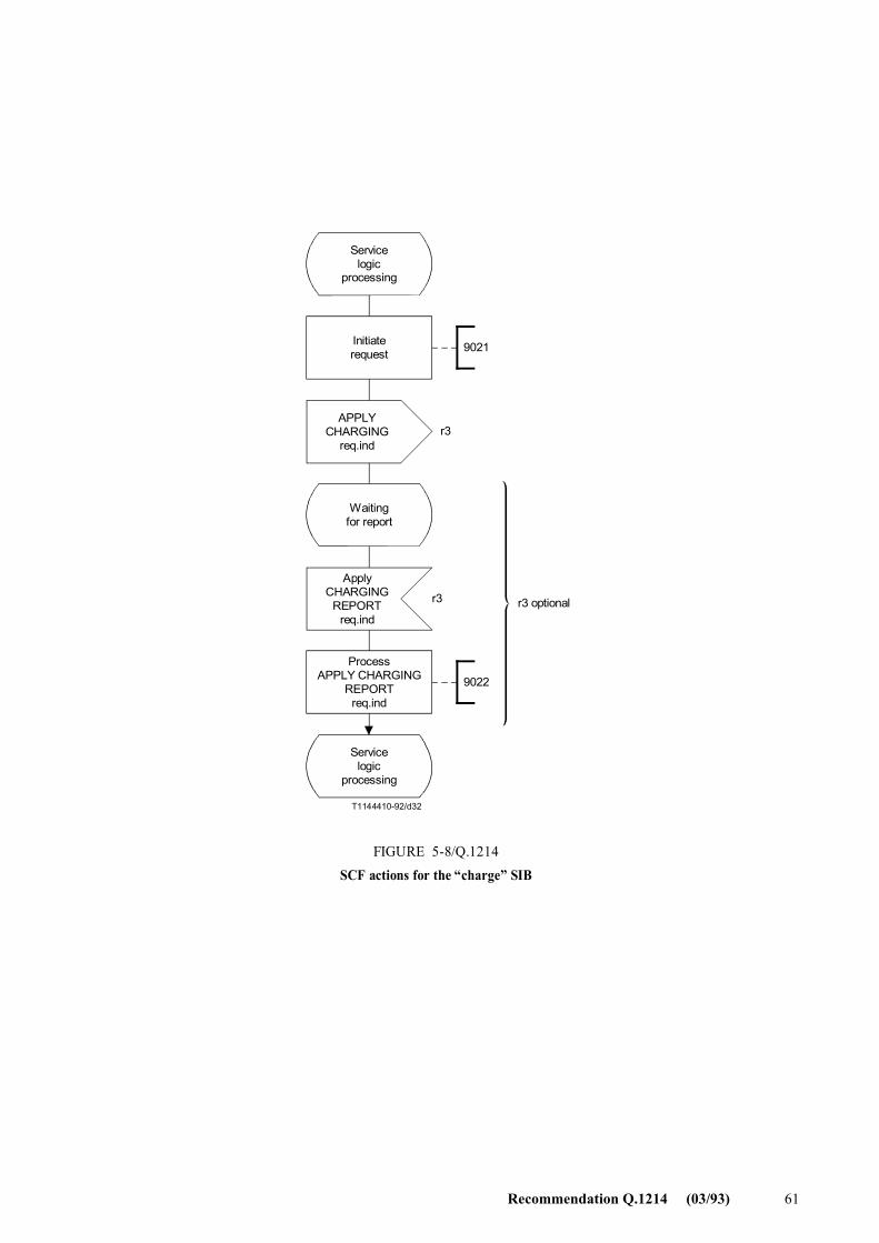
Recommendation Q.1214 (03/93) 61
T1144410-92/d32
9021
9022
r3
r3
Servicelogic
processing
Initiaterequest
APPLYCHARGING
req.ind
Waitingfor report
ApplyCHARGING
REPORTreq.ind
ProcessAPPLY CHARGING
REPORTreq.ind
Servicelogic
processing
r3 optional
FIGURE 5-8/Q.1214SCF actions for the �charge� SIB
FIGURE 5-8/Q.1214...[D32] = 16 CM
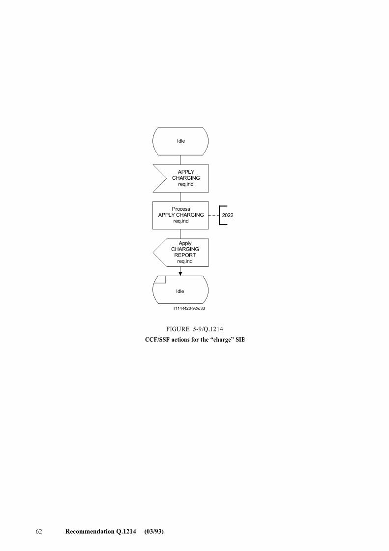
62 Recommendation Q.1214 (03/93)
T1144420-92/d33
2022
Idle
APPLYCHARGING
req.ind
ApplyCHARGING
REPORTreq.ind
ProcessAPPLY CHARGING
req.ind
FIGURE 5-9/Q.1214CCF/SSF actions for the �charge� SIB
Idle
FIGURE 5-9/Q.1214...[D33] = 12 CM
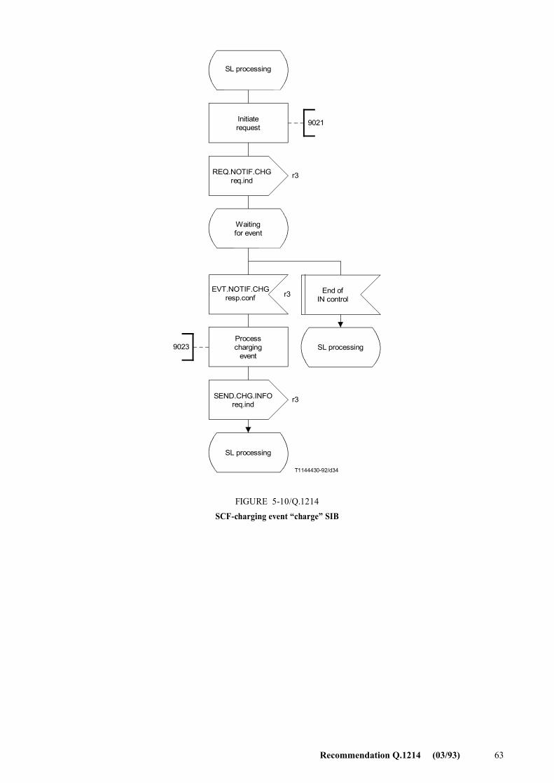
Recommendation Q.1214 (03/93) 63
T1144430-92/d34
9021
9023
r3
r3
r3
SL processing
Initiaterequest
REQ.NOTIF.CHGreq.ind
Waitingfor event
EVT.NOTIF.CHGresp.conf
End ofIN control
Processcharging
eventSL processing
SEND.CHG.INFOreq.ind
FIGURE 5-10/Q.1214SCF-charging event �charge� SIB
SL processing
FIGURE 5-10/Q.1214...[D34] = 18.5 CM
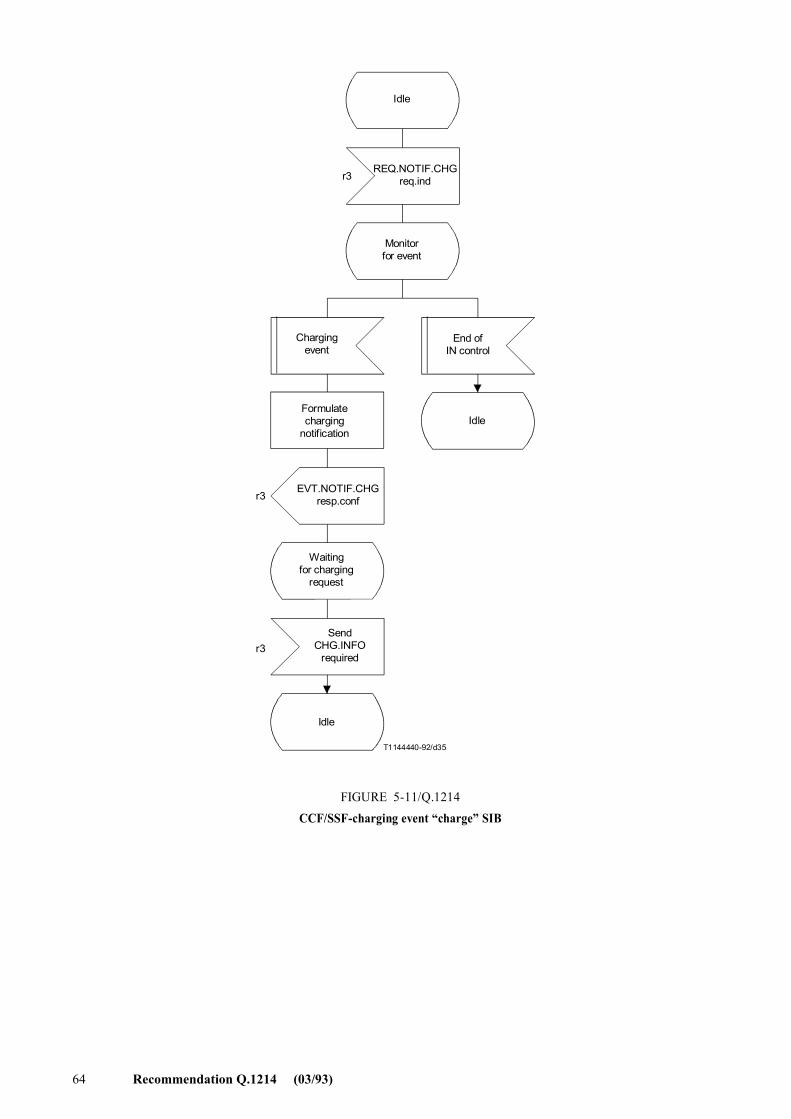
64 Recommendation Q.1214 (03/93)
T1144440-92/d35
r3
r3
r3
Idle
REQ.NOTIF.CHGreq.ind
EVT.NOTIF.CHGresp.conf
End ofIN control
Waitingfor charging
request
Formulatecharging
notification
SendCHG.INFO
required
Monitorfor event
Chargingevent
Idle
Idle
FIGURE 5-11/Q.1214CCF/SSF-charging event �charge� SIB
FIGURE 5-11/Q.1214...[D35] = 21 CM PAGE PLEINE
Recommendation Q.1214 (03/93) 65
5.2.2.4 Functional entity actions
Functional entities are assumed to have the basic capabilities required to properly perform their assigned function in the IN. Only functional entity actions (FEAs) pertinent to the �charge� SIB are shown in the information flow diagrams. Reference numbers have been arbitrarily assigned to cross-reference the FEAs shown in Figures 5-3, 5-4, and 5-5 with these descriptions:
Reference number Action
9021 Initiate request
� initiate a furnish charging information req.ind, or
� initiate an apply charging req.ind and await a response, or
� initiate a request notification charging event req.ind and await a response
2021 Process furnish charging information req.ind
� receive and analyse furnish charging information req.ind
� apply specified furnish charging information procedures
2022 Process apply charging req.ind
� receive and analyse apply charging req.ind
� apply specified apply charging procedures (generate pulses)
9022 Process apply charging report req.ind
� return an apply charging report req.ind
2023 Process request notification charging event req.ind
� receive and analyse request notification charging event req.ind
� apply specified request notification charging event procedures
� monitor for specified charging event
9023 Process event notification charging req.ind
� on detection of specified charging event, send event notification
� charging req.ind
2024 Process send charging information req.ind
� receive and analyse send charging information req.ind
� apply specified send charging information procedures.
5.2.3 Compare SIB
5.2.3.1 Description
The compare SIB provides the capability to compare an identifier against a specified reference value and will return in one of three possible solutions, (<, >, or =). This capability is provided, for CS-1, in the SCF as a part of the service logic for IN service features. As a result, no information flows are directly associated with this capability.
5.2.3.2 Information flows
No IFs are required for this SIB in CS-1.
5.2.3.3 SDLs
Figure 5-12 presents the SDL diagram for the SCF processing of the compare SIB.
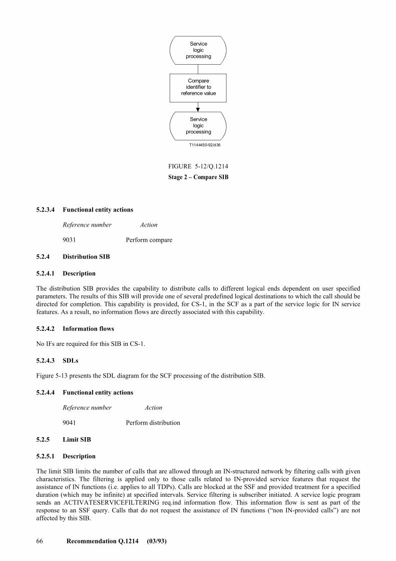
66 Recommendation Q.1214 (03/93)
T1144450-92/d36
Servicelogic
processing
Compareidentifier to
reference value
FIGURE 5-12/Q.1214Stage 2 � Compare SIB
Servicelogic
processing
FIGURE 5-12/Q.1214...[D36] = 7.5 CM
5.2.3.4 Functional entity actions
Reference number Action
9031 Perform compare
5.2.4 Distribution SIB
5.2.4.1 Description
The distribution SIB provides the capability to distribute calls to different logical ends dependent on user specified parameters. The results of this SIB will provide one of several predefined logical destinations to which the call should be directed for completion. This capability is provided, for CS-1, in the SCF as a part of the service logic for IN service features. As a result, no information flows are directly associated with this capability.
5.2.4.2 Information flows
No IFs are required for this SIB in CS-1.
5.2.4.3 SDLs
Figure 5-13 presents the SDL diagram for the SCF processing of the distribution SIB.
5.2.4.4 Functional entity actions
Reference number Action
9041 Perform distribution
5.2.5 Limit SIB
5.2.5.1 Description
The limit SIB limits the number of calls that are allowed through an IN-structured network by filtering calls with given characteristics. The filtering is applied only to those calls related to IN-provided service features that request the assistance of IN functions (i.e. applies to all TDPs). Calls are blocked at the SSF and provided treatment for a specified duration (which may be infinite) at specified intervals. Service filtering is subscriber initiated. A service logic program sends an ACTIVATESERVICEFILTERING req.ind information flow. This information flow is sent as part of the response to an SSF query. Calls that do not request the assistance of IN functions (�non IN-provided calls�) are not affected by this SIB.
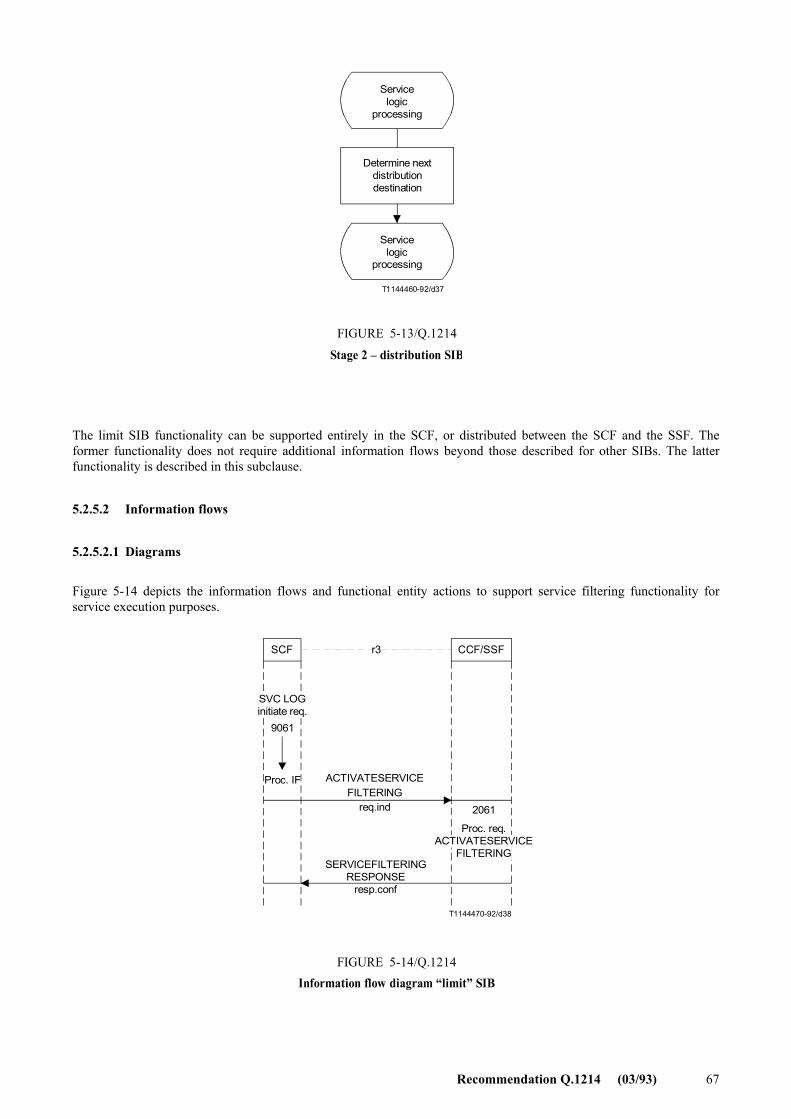
Recommendation Q.1214 (03/93) 67
T1144460-92/d37
Servicelogic
processing
Determine nextdistributiondestination
FIGURE 5-13/Q.1214
Stage 2 � distribution SIB
Servicelogic
processing
FIGURE 5-13/Q.1214...[D37] = 7.5 CM
The limit SIB functionality can be supported entirely in the SCF, or distributed between the SCF and the SSF. The former functionality does not require additional information flows beyond those described for other SIBs. The latter functionality is described in this subclause.
5.2.5.2 Information flows
5.2.5.2.1 Diagrams
Figure 5-14 depicts the information flows and functional entity actions to support service filtering functionality for service execution purposes.
T1144470-92/d38
SCF CCF/SSFr3
Proc. IF ACTIVATESERVICEFILTERING
req.ind
FIGURE 5-14/Q.1214Information flow diagram �limit� SIB
SVC LOGinitiate req.
9061
SERVICEFILTERINGRESPONSE
resp.conf
2061
Proc. req.ACTIVATESERVICE
FILTERING
FIGURE 5-14/Q.1214 [D38] = 9.5 CM = 9 CM
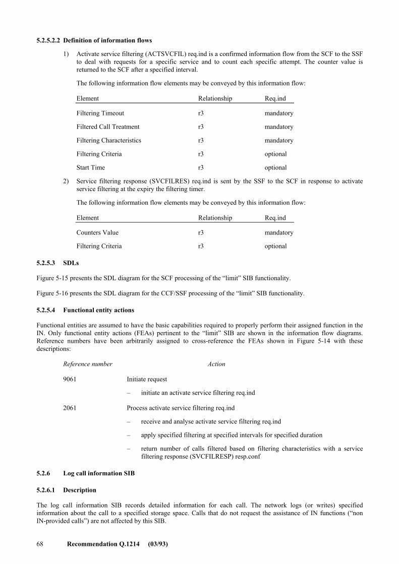
68 Recommendation Q.1214 (03/93)
5.2.5.2.2 Definition of information flows
1) Activate service filtering (ACTSVCFIL) req.ind is a confirmed information flow from the SCF to the SSF to deal with requests for a specific service and to count each specific attempt. The counter value is returned to the SCF after a specified interval.
The following information flow elements may be conveyed by this information flow:
Element Relationship Req.ind
Filtering Timeout r3 mandatory
Filtered Call Treatment r3 mandatory
Filtering Characteristics r3 mandatory
Filtering Criteria r3 optional
Start Time r3 optional
2) Service filtering response (SVCFILRES) req.ind is sent by the SSF to the SCF in response to activate service filtering at the expiry the filtering timer.
The following information flow elements may be conveyed by this information flow:
Element Relationship Req.ind
Counters Value r3 mandatory
Filtering Criteria r3 optional
5.2.5.3 SDLs
Figure 5-15 presents the SDL diagram for the SCF processing of the �limit� SIB functionality.
Figure 5-16 presents the SDL diagram for the CCF/SSF processing of the �limit� SIB functionality.
5.2.5.4 Functional entity actions
Functional entities are assumed to have the basic capabilities required to properly perform their assigned function in the IN. Only functional entity actions (FEAs) pertinent to the �limit� SIB are shown in the information flow diagrams. Reference numbers have been arbitrarily assigned to cross-reference the FEAs shown in Figure 5-14 with these descriptions:
Reference number Action
9061 Initiate request
� initiate an activate service filtering req.ind
2061 Process activate service filtering req.ind
� receive and analyse activate service filtering req.ind
� apply specified filtering at specified intervals for specified duration
� return number of calls filtered based on filtering characteristics with a service filtering response (SVCFILRESP) resp.conf
5.2.6 Log call information SIB
5.2.6.1 Description
The log call information SIB records detailed information for each call. The network logs (or writes) specified information about the call to a specified storage space. Calls that do not request the assistance of IN functions (�non IN-provided calls�) are not affected by this SIB.
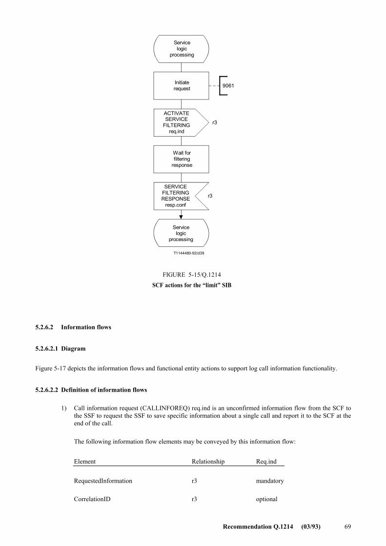
Recommendation Q.1214 (03/93) 69
T1144480-92/d39
9061
r3
r3
Servicelogic
processing
Initiaterequest
ACTIVATESERVICE
FILTERINGreq.ind
Wait forfiltering
response
FIGURE 5-15/Q.1214SCF actions for the �limit� SIB
SERVICEFILTERINGRESPONSE
resp.conf
Servicelogic
processing
FIGURE 5-15/Q.1214...[D39] = 14 CM
5.2.6.2 Information flows
5.2.6.2.1 Diagram
Figure 5-17 depicts the information flows and functional entity actions to support log call information functionality.
5.2.6.2.2 Definition of information flows
1) Call information request (CALLINFOREQ) req.ind is an unconfirmed information flow from the SCF to the SSF to request the SSF to save specific information about a single call and report it to the SCF at the end of the call.
The following information flow elements may be conveyed by this information flow:
Element Relationship Req.ind
RequestedInformation r3 mandatory
CorrelationID r3 optional
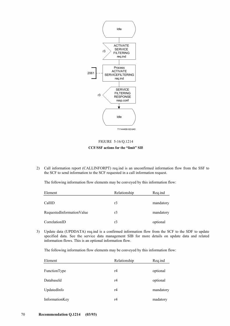
70 Recommendation Q.1214 (03/93)
T1144490-92/d40
2061
r3
r3
Idle
ACTIVATESERVICE
FILTERINGreq.ind
FIGURE 5-16/Q.1214CCF/SSF actions for the �limit� SIB
Idle
ProcessACTIVATE
SERVICEFILTERINGreq.ind
SERVICEFILTERINGRESPONSE
resp.conf
FIGURE 5-16/Q.1214...[D40] = 12 CM
2) Call information report (CALLINFORPT) req.ind is an unconfirmed information flow from the SSF to the SCF to send information to the SCF requested in a call information request.
The following information flow elements may be conveyed by this information flow:
Element Relationship Req.ind
CallID r3 mandatory
RequestedInformationValue r3 mandatory
CorrelationID r3 optional
3) Update data (UPDDATA) req.ind is a confirmed information flow from the SCF to the SDF to update specified data. See the service data management SIB for more details on update data and related information flows. This is an optional information flow.
The following information flow elements may be conveyed by this information flow:
Element Relationship Req.ind
FunctionType r4 optional
DatabaseId r4 optional
UpdatedInfo r4 mandatory
InformationKey r4 madatory
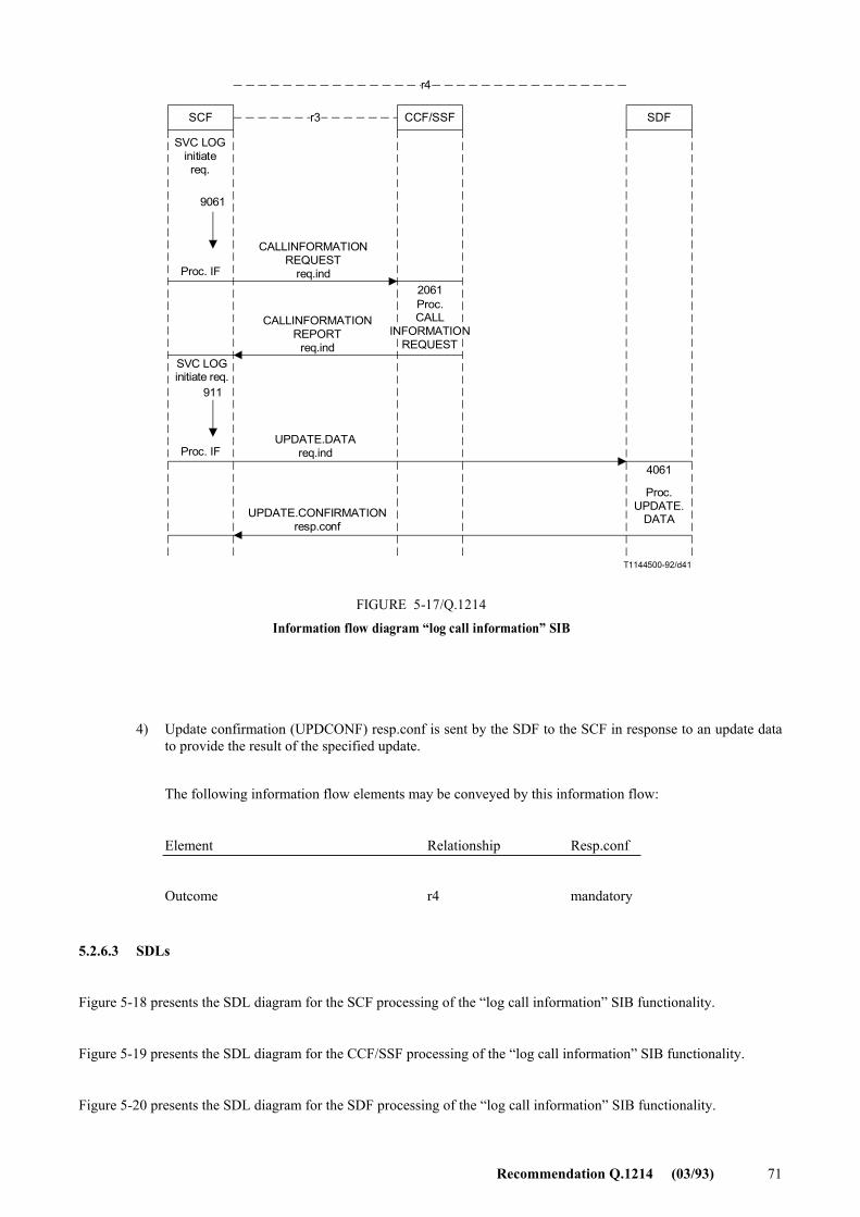
Recommendation Q.1214 (03/93) 71
T1144500-92/d41
CCF/SSFr3SCF SDF
r4
SVC LOGinitiatereq.
9061
Proc. IF
911
CALLINFORMATIONREQUEST
req.ind
CALLINFORMATIONREPORT
req.ind
UPDATE.DATAreq.ind
UPDATE.CONFIRMATIONresp.conf
2061
4061
Proc.UPDATE.
DATA
FIGURE 5-17/Q.1214
Information flow diagram �log call information� SIB
SVC LOGinitiate req.
Proc. IF
Proc.CALL
INFORMATIONREQUEST
FIGURE 5-17/Q.1214...[D41] = 14 CM
4) Update confirmation (UPDCONF) resp.conf is sent by the SDF to the SCF in response to an update data to provide the result of the specified update.
The following information flow elements may be conveyed by this information flow:
Element Relationship Resp.conf
Outcome r4 mandatory
5.2.6.3 SDLs
Figure 5-18 presents the SDL diagram for the SCF processing of the �log call information� SIB functionality.
Figure 5-19 presents the SDL diagram for the CCF/SSF processing of the �log call information� SIB functionality.
Figure 5-20 presents the SDL diagram for the SDF processing of the �log call information� SIB functionality.
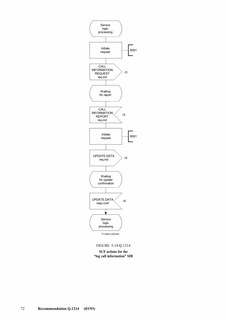
72 Recommendation Q.1214 (03/93)
T1144510-92/d42
9061
9061
r3
r3
r4
r4
Servicelogic
processing
Initiaterequest
CALLINFORMATION
REQUESTreq.ind
Waitingfor report
FIGURE 5-18/Q.1214SCF actions for the
�log call information� SIB
CALLINFORMATION
REPORTreq.ind
Initiaterequest
UPDATE.DATAreq.ind
Waitingfor update
confirmation
UPDATE.DATAresp.conf
Servicelogic
processing
FIGURE 5-18/Q.1214...[D42] = 21 CM PAGE PLEINE
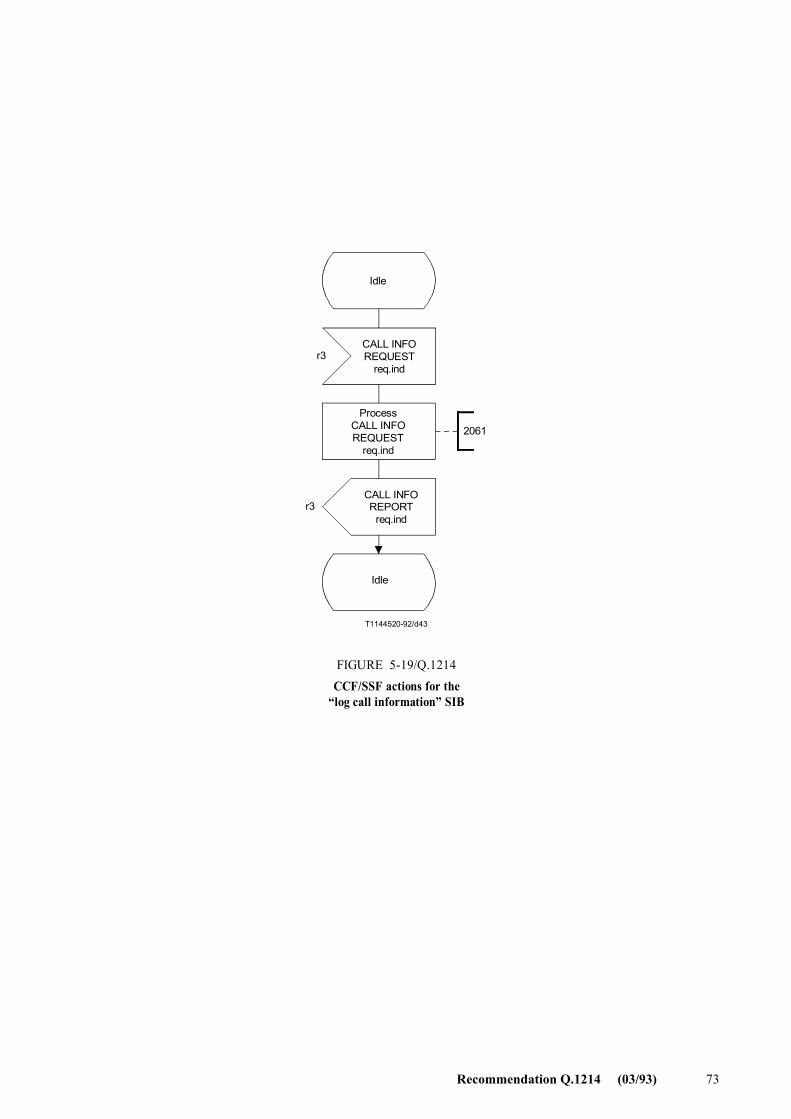
Recommendation Q.1214 (03/93) 73
T1144520-92/d43
2061
r3
r3
Idle
CALL INFOREQUEST
req.ind
FIGURE 5-19/Q.1214CCF/SSF actions for the
�log call information� SIB
CALL INFOREPORT
req.ind
ProcessCALL INFOREQUEST
req.ind
Idle
FIGURE 5-19/Q.1214...[D43] = 12.5 CM
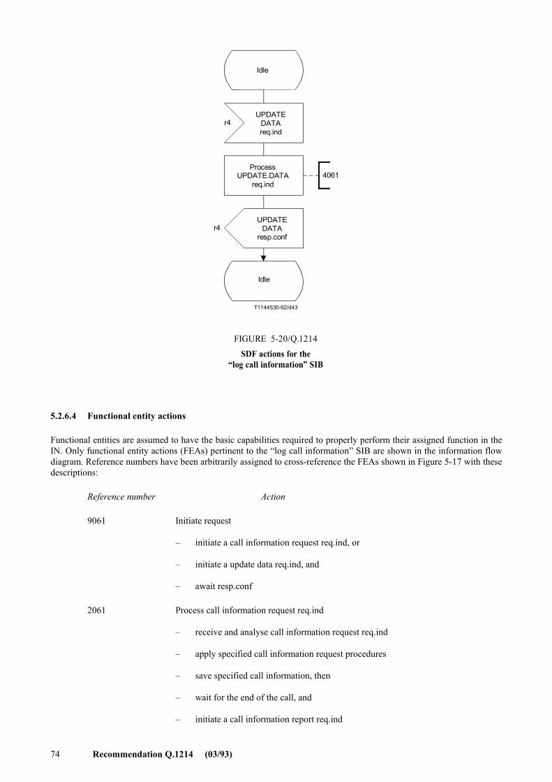
74 Recommendation Q.1214 (03/93)
T1144530-92/d43
4061
r4
r4
Idle
UPDATEDATAreq.ind
FIGURE 5-20/Q.1214
SDF actions for the�log call information� SIB
UPDATEDATA
resp.conf
ProcessUPDATE.DATA
req.ind
Idle
FIGURE 5-20/Q.1214...[D44] = 12.5 CM
5.2.6.4 Functional entity actions
Functional entities are assumed to have the basic capabilities required to properly perform their assigned function in the IN. Only functional entity actions (FEAs) pertinent to the �log call information� SIB are shown in the information flow diagram. Reference numbers have been arbitrarily assigned to cross-reference the FEAs shown in Figure 5-17 with these descriptions:
Reference number Action
9061 Initiate request
� initiate a call information request req.ind, or
� initiate a update data req.ind, and
� await resp.conf
2061 Process call information request req.ind
� receive and analyse call information request req.ind
� apply specified call information request procedures
� save specified call information, then
� wait for the end of the call, and
� initiate a call information report req.ind
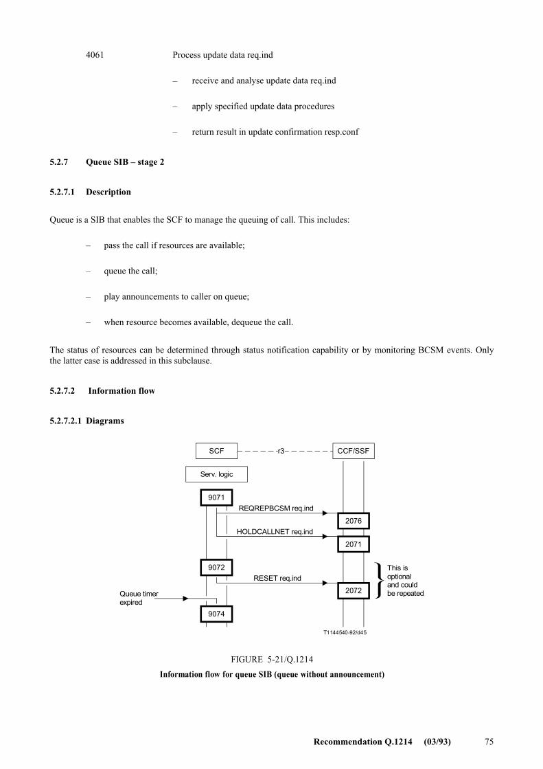
Recommendation Q.1214 (03/93) 75
4061 Process update data req.ind
� receive and analyse update data req.ind
� apply specified update data procedures
� return result in update confirmation resp.conf
5.2.7 Queue SIB � stage 2
5.2.7.1 Description
Queue is a SIB that enables the SCF to manage the queuing of call. This includes:
� pass the call if resources are available;
� queue the call;
� play announcements to caller on queue;
� when resource becomes available, dequeue the call.
The status of resources can be determined through status notification capability or by monitoring BCSM events. Only the latter case is addressed in this subclause.
5.2.7.2 Information flow
5.2.7.2.1 Diagrams
T1144540-92/d45
SCF CCF/SSFr3
9071
9072
9074
2076
2071
2072
Serv. logic
REQREPBCSM req.ind
HOLDCALLNET req.ind
RESET req.ind
Queue timerexpired
This isoptionaland couldbe repeated
FIGURE 5-21/Q.1214
Information flow for queue SIB (queue without announcement)
FIGURE 5-21/Q.1214...[D45] = 9 CM
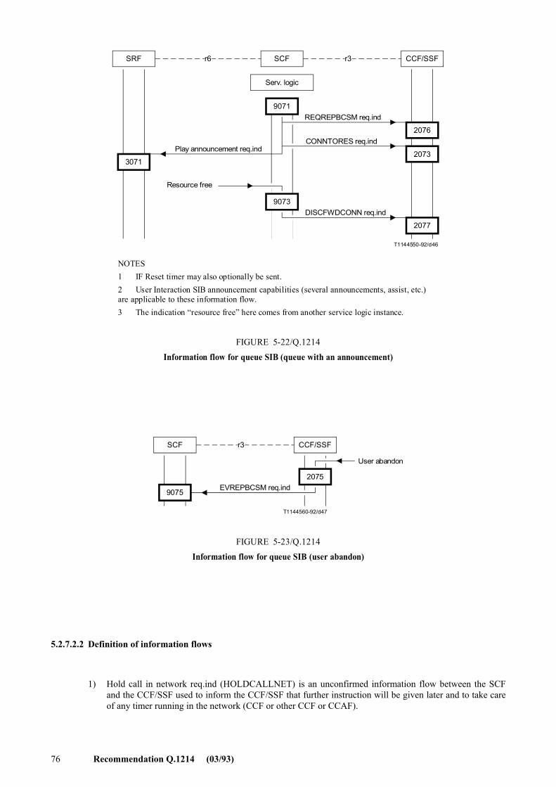
76 Recommendation Q.1214 (03/93)
T1144550-92/d46
SCF CCF/SSFr3
9071
9073
2076
2073
2077
SRF r6
3071
Serv. logic
REQREPBCSM req.ind
CONNTORES req.ind
DISCFWDCONN req.ind
Resource free
Play announcement req.ind
NOTES1 IF Reset timer may also optionally be sent.2 User Interaction SIB announcement capabilities (several announcements, assist, etc.) are applicable to these information flow.3 The indication �resource free� here comes from another service logic instance.
FIGURE 5-22/Q.1214Information flow for queue SIB (queue with an announcement)
FIGURE 5-22/Q.1214...[D46] = 11.5 CM
T1144560-92/d47
SCF CCF/SSFr3
9075
2075EVREPBCSM req.ind
User abandon
FIGURE 5-23/Q.1214Information flow for queue SIB (user abandon)
FIGURE 5-2/3Q.1214...[D47] = 5 CM
5.2.7.2.2 Definition of information flows
1) Hold call in network req.ind (HOLDCALLNET) is an unconfirmed information flow between the SCF and the CCF/SSF used to inform the CCF/SSF that further instruction will be given later and to take care of any timer running in the network (CCF or other CCF or CCAF).
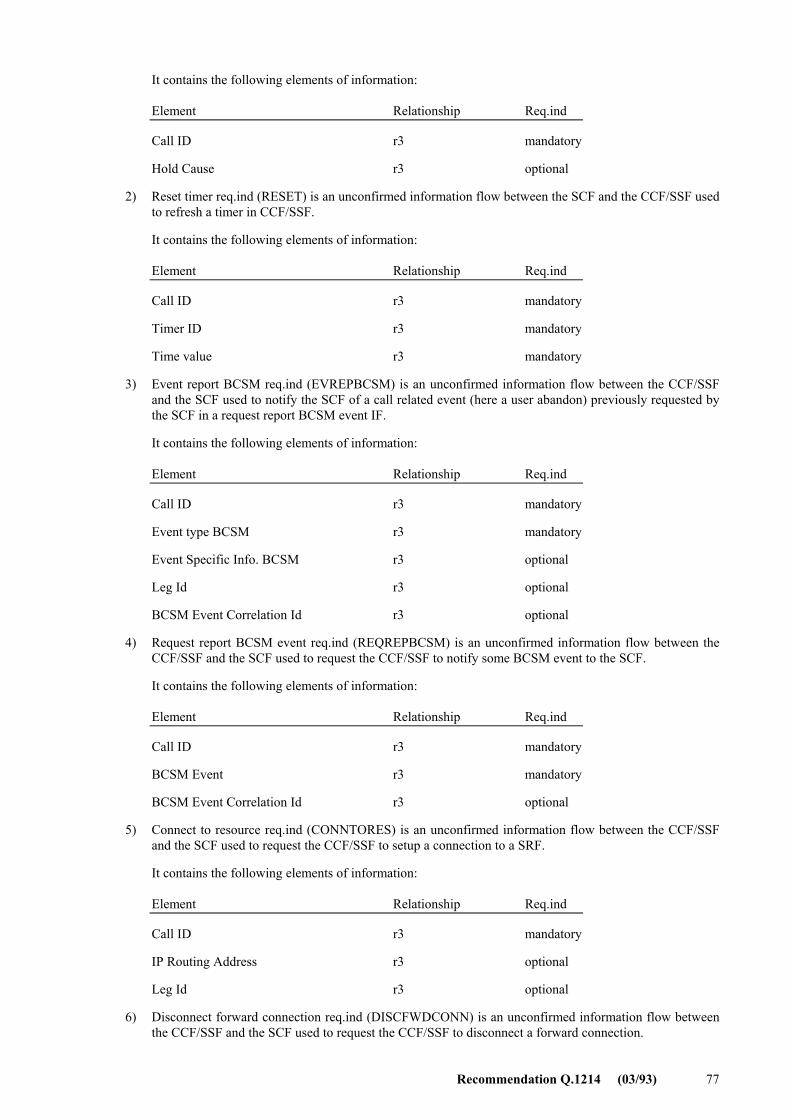
Recommendation Q.1214 (03/93) 77
It contains the following elements of information:
Element Relationship Req.ind
Call ID r3 mandatory
Hold Cause r3 optional
2) Reset timer req.ind (RESET) is an unconfirmed information flow between the SCF and the CCF/SSF used to refresh a timer in CCF/SSF.
It contains the following elements of information:
Element Relationship Req.ind
Call ID r3 mandatory
Timer ID r3 mandatory
Time value r3 mandatory
3) Event report BCSM req.ind (EVREPBCSM) is an unconfirmed information flow between the CCF/SSF and the SCF used to notify the SCF of a call related event (here a user abandon) previously requested by the SCF in a request report BCSM event IF.
It contains the following elements of information:
Element Relationship Req.ind
Call ID r3 mandatory
Event type BCSM r3 mandatory
Event Specific Info. BCSM r3 optional
Leg Id r3 optional
BCSM Event Correlation Id r3 optional
4) Request report BCSM event req.ind (REQREPBCSM) is an unconfirmed information flow between the CCF/SSF and the SCF used to request the CCF/SSF to notify some BCSM event to the SCF.
It contains the following elements of information:
Element Relationship Req.ind
Call ID r3 mandatory
BCSM Event r3 mandatory
BCSM Event Correlation Id r3 optional
5) Connect to resource req.ind (CONNTORES) is an unconfirmed information flow between the CCF/SSF and the SCF used to request the CCF/SSF to setup a connection to a SRF.
It contains the following elements of information:
Element Relationship Req.ind
Call ID r3 mandatory
IP Routing Address r3 optional
Leg Id r3 optional
6) Disconnect forward connection req.ind (DISCFWDCONN) is an unconfirmed information flow between the CCF/SSF and the SCF used to request the CCF/SSF to disconnect a forward connection.
78 Recommendation Q.1214 (03/93)
It contains the following elements of information:
Element Relationship Req.ind
Call ID r3 mandatory
7) Play announcement req.ind (PLAYANN) is an unconfirmed information flow between the SCF and the SRF used to request the SRF to play an announcement.
It contains the following elements of information:
Element Relationship Req.ind
SRF Connect Id r3 mandatory
Information to Send r3 mandatory
Disconnect from IP forbidden r3 optional
5.2.7.2.3 SDLs
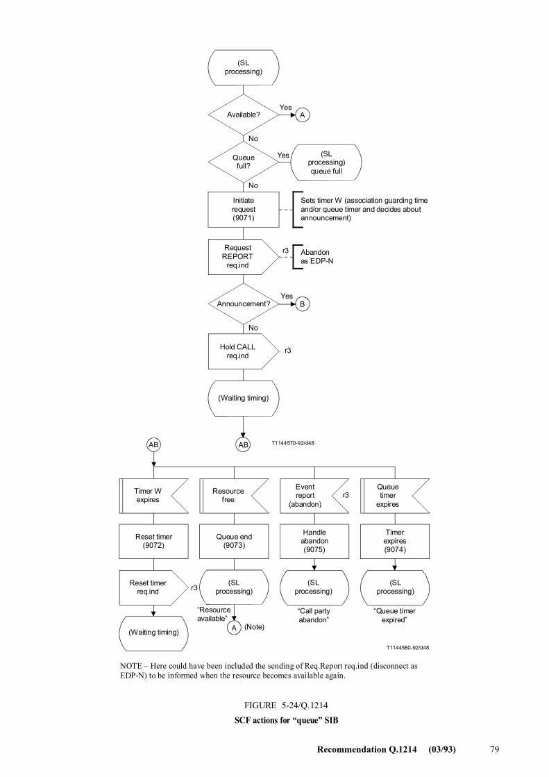
Recommendation Q.1214 (03/93) 79
T1144570-92/d48
A
B
AB
A
AB
T1144580-92/d48
r3
r3
r3
(SLprocessing)
Available?
Queuefull?
Yes
No
Yes
No
(SLprocessing)queue full
Initiaterequest(9071)
RequestREPORT
req.ind
Sets timer W (association guarding timeand/or queue timer and decides aboutannouncement)
Abandonas EDP-N
r3
Announcement?
No
Hold CALLreq.ind
(Waiting timing)
Timer Wexpires
Resourcefree
Eventreport
(abandon)
Queuetimer
expires
Reset timer(9072)
Queue end(9073)
Handleabandon(9075)
Timerexpires(9074)
Reset timerreq.ind
(SLprocessing)
�Resourceavailable�
(Note)
�Call partyabandon�
�Queue timerexpired�
(Waiting timing)
NOTE � Here could have been included the sending of Req.Report req.ind (disconnect as EDP-N) to be informed when the resource becomes available again.
FIGURE 5-24/Q.1214SCF actions for �queue� SIB
Yes
(SLprocessing)
(SLprocessing)
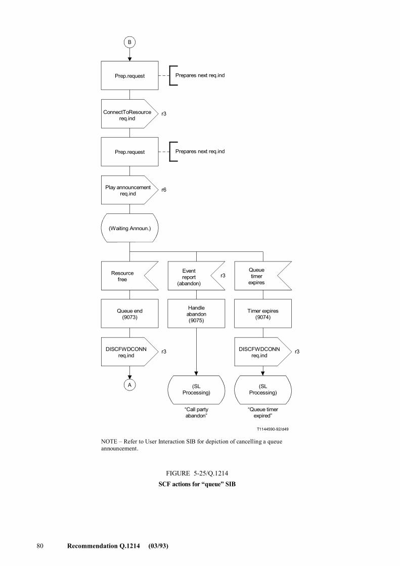
80 Recommendation Q.1214 (03/93)
T1144590-92/d49
B
A
r3
r6
r3
r3 r3
Prep.request Prepares next req.ind
ConnectToResourcereq.ind
Play announcementreq.ind
(Waiting Announ.)
Resourcefree
Eventreport
(abandon)
Queuetimer
expires
Queue end(9073)
Handleabandon(9075)
Timer expires(9074)
DISCFWDCONNreq.ind
(SLProcessing)
�Call partyabandon�
�Queue timerexpired�
NOTE � Refer to User Interaction SIB for depiction of cancelling a queue announcement.
FIGURE 5-25/Q.1214SCF actions for �queue� SIB
Prepares next req.indPrep.request
DISCFWDCONNreq.ind
(SLProcessing)
FIGURE 5-25/Q.1214...[D49] = 21 CM PAGE PLEINE
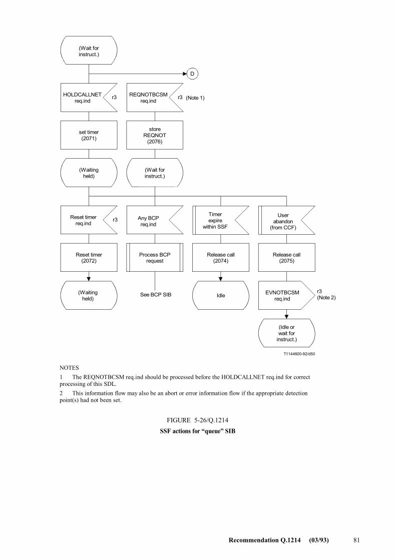
Recommendation Q.1214 (03/93) 81
D
T1144600-92/d50
r3 r3
r3
r3
(Wait forinstruct.)
HOLDCALLNETreq.ind
REQNOTBCSMreq.ind
set timer(2071)
storeREQNOT
(2076)
(Waitingheld)
(Wait forinstruct.)
Reset timerreq.ind
Any BCPreq.ind
Timerexpire
within SSF
Userabandon
(from CCF)
Reset timer(2072)
Process BCPrequest
Release call(2074)
Release call(2075)
(Waitingheld) Idle EVNOTBCSM
req.ind
(Idle orwait for
instruct.)
See BCP SIB (Note 2)
(Note 1)
NOTES1 The REQNOTBCSM req.ind should be processed before the HOLDCALLNET req.ind for correct processing of this SDL.2 This information flow may also be an abort or error information flow if the appropriate detection point(s) had not been set.
FIGURE 5-26/Q.1214SSF actions for �queue� SIB
FIGURE 5-26/Q.1214...[D50] = 21 CM PAGE PLEINE
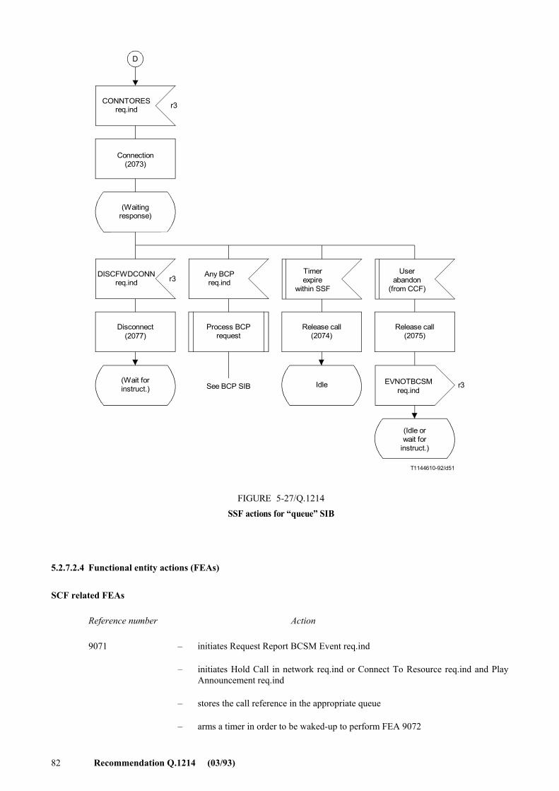
82 Recommendation Q.1214 (03/93)
T1144610-92/d51
D
r3
r3
r3
CONNTORESreq.ind
DISCFWDCONNreq.ind
(Waitingresponse)
(Wait forinstruct.)
Any BCPreq.ind
Timerexpire
within SSF
Userabandon
(from CCF)
Connection(2073)
Process BCPrequest
Release call(2074)
Release call(2075)
Disconnect(2077)
Idle EVNOTBCSMreq.ind
(Idle orwait for
instruct.)
See BCP SIB
FIGURE 5-27/Q.1214SSF actions for �queue� SIB
FIGURE 5-27/Q.1214...[D51] = 17.5 CM
5.2.7.2.4 Functional entity actions (FEAs)
SCF related FEAs
Reference number Action
9071 � initiates Request Report BCSM Event req.ind
� initiates Hold Call in network req.ind or Connect To Resource req.ind and Play Announcement req.ind
� stores the call reference in the appropriate queue
� arms a timer in order to be waked-up to perform FEA 9072
Recommendation Q.1214 (03/93) 83
9072 � wakes up from timer set in FEA 9071
� initiates Reset Timer req.ind
� arms a timer in order to be waked-up to start FEA 9072 again
9073 � dequeues call attempt based on availability of destination
� initiates, when needed, Forward Disconnect req.ind
� updates the resource status (here increases the line busy counter related to concerned destination)
� gives control back to service logic with �resource available�
9074 � wakes up from application queue timer
� gives control back to service logic with �timer expired�
9075 � receives Event Report BCSM req.ind, indicating user abandon
� gives control back to service logic with �call party abandon�
SSF related FEAs
Reference number Action
2071 � receives Hold Call in network req.ind
� requests the CCF to take care of all setup timers running in any CCF or CCAF in the network (how to perform that in CCF is ffs. In ISDN calls, the CALL PROGRESS ISUP message can be used)
2072 � receives Reset Timer req.ind
� updates the value of in_SSF_running timer with the received value
2073 � receives Connect to Resource req.ind
� requests the CCF to connect the party to the relevant SRF
2074 � wakes up from in_SSF_running timer
� takes care of the release of all SSF resources on this call
2075 � receives an user abandon indication from the CCF
� checks that Report of user abandon was requested as EDP
� sends Event Report BCSM req.ind, indicating user abandon
� depending on still armed EDP, either releases all SSF resources on this call, or stay waiting for further SCF instructions
2076 � receives Request Report BCSM Event req.ind from the SCF
� stores the requested Report
2077 � receives Forward Disconnect req.ind
� requests the CCF to disconnect the party from the SRF
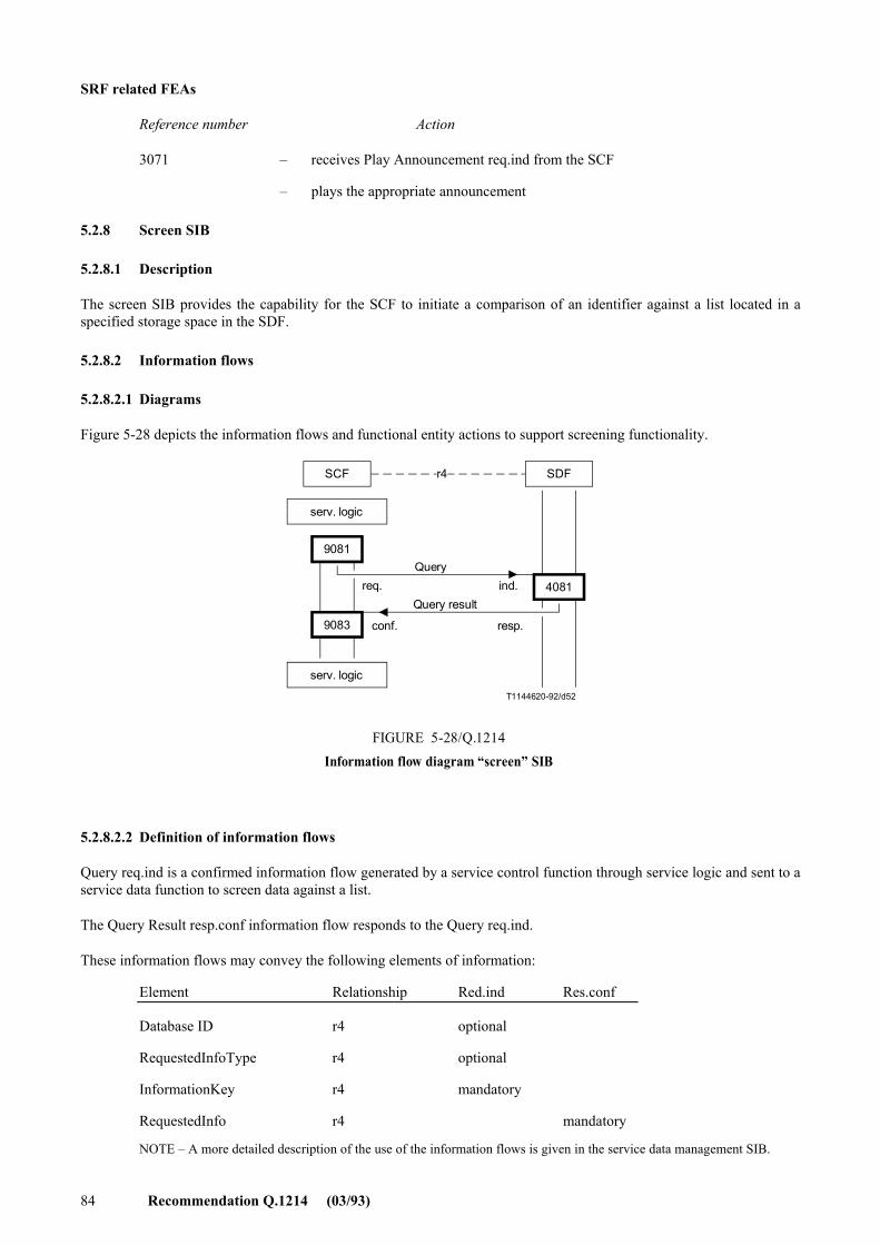
84 Recommendation Q.1214 (03/93)
SRF related FEAs
Reference number Action
3071 � receives Play Announcement req.ind from the SCF
� plays the appropriate announcement
5.2.8 Screen SIB
5.2.8.1 Description
The screen SIB provides the capability for the SCF to initiate a comparison of an identifier against a list located in a specified storage space in the SDF.
5.2.8.2 Information flows
5.2.8.2.1 Diagrams
Figure 5-28 depicts the information flows and functional entity actions to support screening functionality.
T1144620-92/d52
SCF SDFr4
9081
9083
4081
serv. logic
Queryreq. ind.
conf. resp.
FIGURE 5-28/Q.1214Information flow diagram �screen� SIB
serv. logic
Query result
FIGURE 5-28/Q.1214...[D52] = 7.5 CM
5.2.8.2.2 Definition of information flows
Query req.ind is a confirmed information flow generated by a service control function through service logic and sent to a service data function to screen data against a list.
The Query Result resp.conf information flow responds to the Query req.ind.
These information flows may convey the following elements of information:
Element Relationship Red.ind Res.conf
Database ID r4 optional
RequestedInfoType r4 optional
InformationKey r4 mandatory
RequestedInfo r4 mandatory
NOTE � A more detailed description of the use of the information flows is given in the service data management SIB.
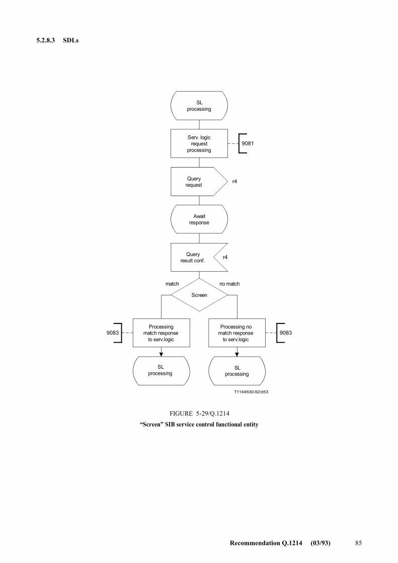
Recommendation Q.1214 (03/93) 85
5.2.8.3 SDLs
T1144630-92/d53
9081
90839083
r4
r4
SLprocessing
Serv. logicrequest
processing
Queryrequest
Awaitresponse
Queryresult conf.
Screen
match no match
Processingmatch response
to serv.logic
SLprocessing
FIGURE 5-29/Q.1214
�Screen� SIB service control functional entity
Processing nomatch response
to serv.logic
SLprocessing
FIGURE 5-29/Q.1214...[D53] = 17.5 CM
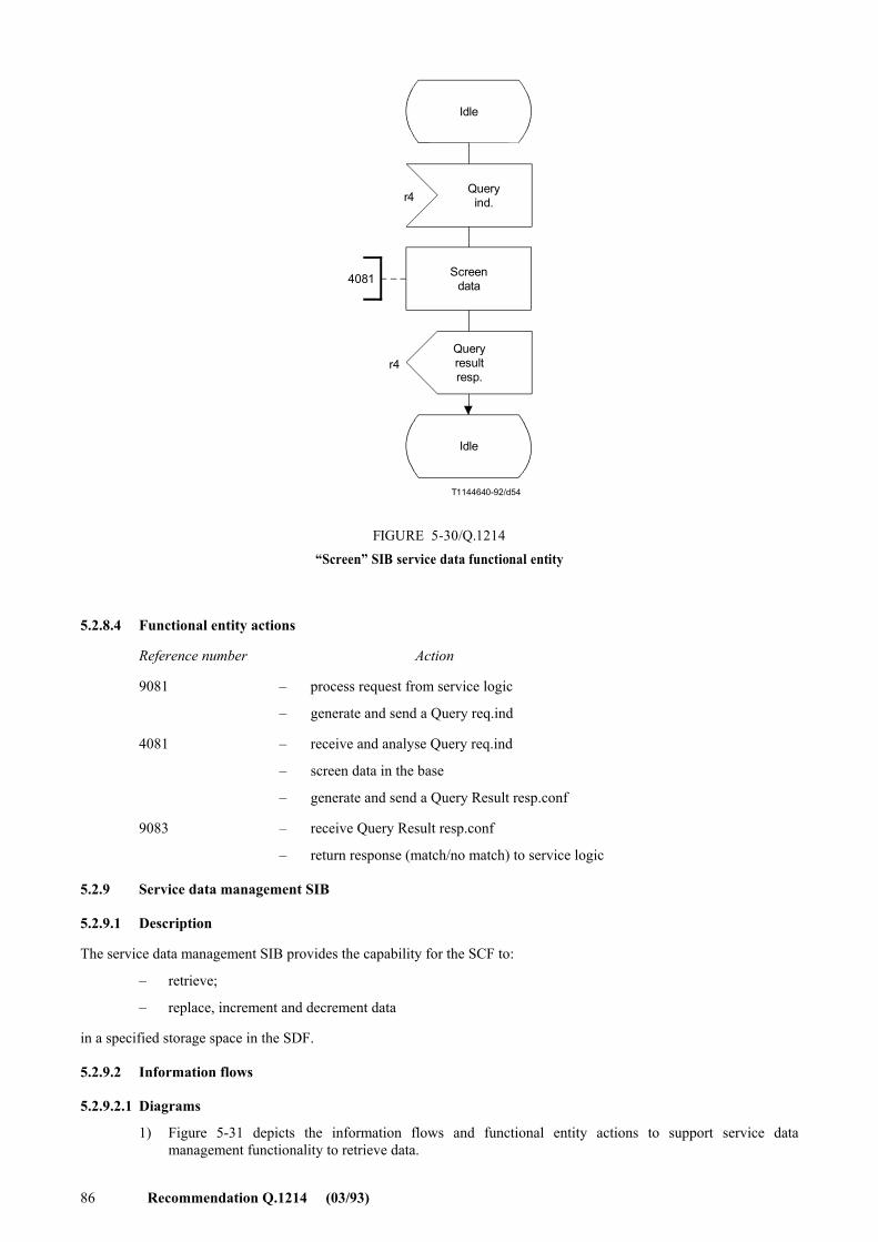
86 Recommendation Q.1214 (03/93)
T1144640-92/d54
4081
r4
r4
Idle
Queryind.
Screendata
Queryresultresp.
FIGURE 5-30/Q.1214�Screen� SIB service data functional entity
Idle
FIGURE 5-30/Q.1214...[D54] = 11 CM
5.2.8.4 Functional entity actions
Reference number Action
9081 � process request from service logic
� generate and send a Query req.ind
4081 � receive and analyse Query req.ind
� screen data in the base
� generate and send a Query Result resp.conf
9083 � receive Query Result resp.conf
� return response (match/no match) to service logic
5.2.9 Service data management SIB
5.2.9.1 Description
The service data management SIB provides the capability for the SCF to:
� retrieve;
� replace, increment and decrement data
in a specified storage space in the SDF.
5.2.9.2 Information flows
5.2.9.2.1 Diagrams
1) Figure 5-31 depicts the information flows and functional entity actions to support service data management functionality to retrieve data.
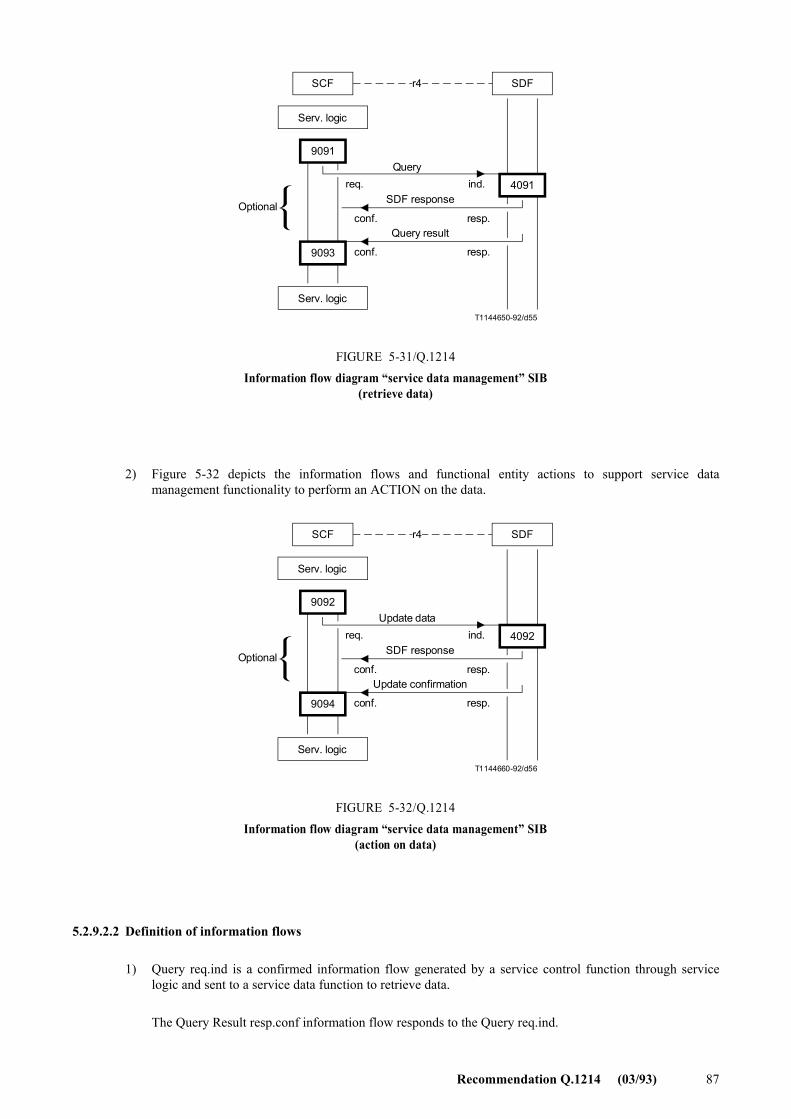
Recommendation Q.1214 (03/93) 87
T1144650-92/d55
SCF SDFr4
9091
9093
4091
Serv. logic
Queryreq. ind.
conf. resp.
FIGURE 5-31/Q.1214Information flow diagram �service data management� SIB
(retrieve data)
Serv. logic
Query result
Optionalconf. resp.
SDF response
FIGURE 5-31/Q.1214...[D55] = 8.5 CM
2) Figure 5-32 depicts the information flows and functional entity actions to support service data management functionality to perform an ACTION on the data.
T1144660-92/d56
SCF SDFr4
9092
9094
4092
Serv. logic
Update datareq. ind.
conf. resp.
FIGURE 5-32/Q.1214Information flow diagram �service data management� SIB
(action on data)
Serv. logic
Update confirmation
Optionalconf. resp.
SDF response
FIGURE 5-32/Q.1214...[D56] = 8.5 CM
5.2.9.2.2 Definition of information flows
1) Query req.ind is a confirmed information flow generated by a service control function through service logic and sent to a service data function to retrieve data.
The Query Result resp.conf information flow responds to the Query req.ind.
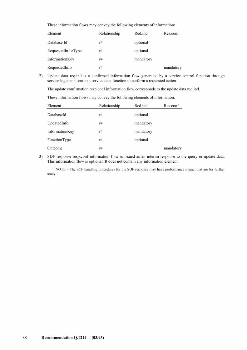
88 Recommendation Q.1214 (03/93)
These information flows may convey the following elements of information:
Element Relationship Red.ind Res.conf
Database Id r4 optional
RequestedInforType r4 optional
InformationKey r4 mandatory
RequestedInfo r4 mandatory
2) Update data req.ind is a confirmed information flow generated by a service control function through service logic and sent to a service data function to perform a requested action.
The update confirmation resp.conf information flow corresponds to the update data req.ind.
These information flows may convey the following elements of information:
Element Relationship Red.ind Res.conf
DatabaseId r4 optional
UpdatedInfo r4 mandatory
InformationKey r4 mandatory
FunctionType r4 optional
Outcome r4 mandatory
3) SDF response resp.conf information flow is issued as an interim response to the query or update data. This information flow is optional. It does not contain any information element.
NOTE � The SCF handling procedures for the SDF response may have performance impact that are for further study.
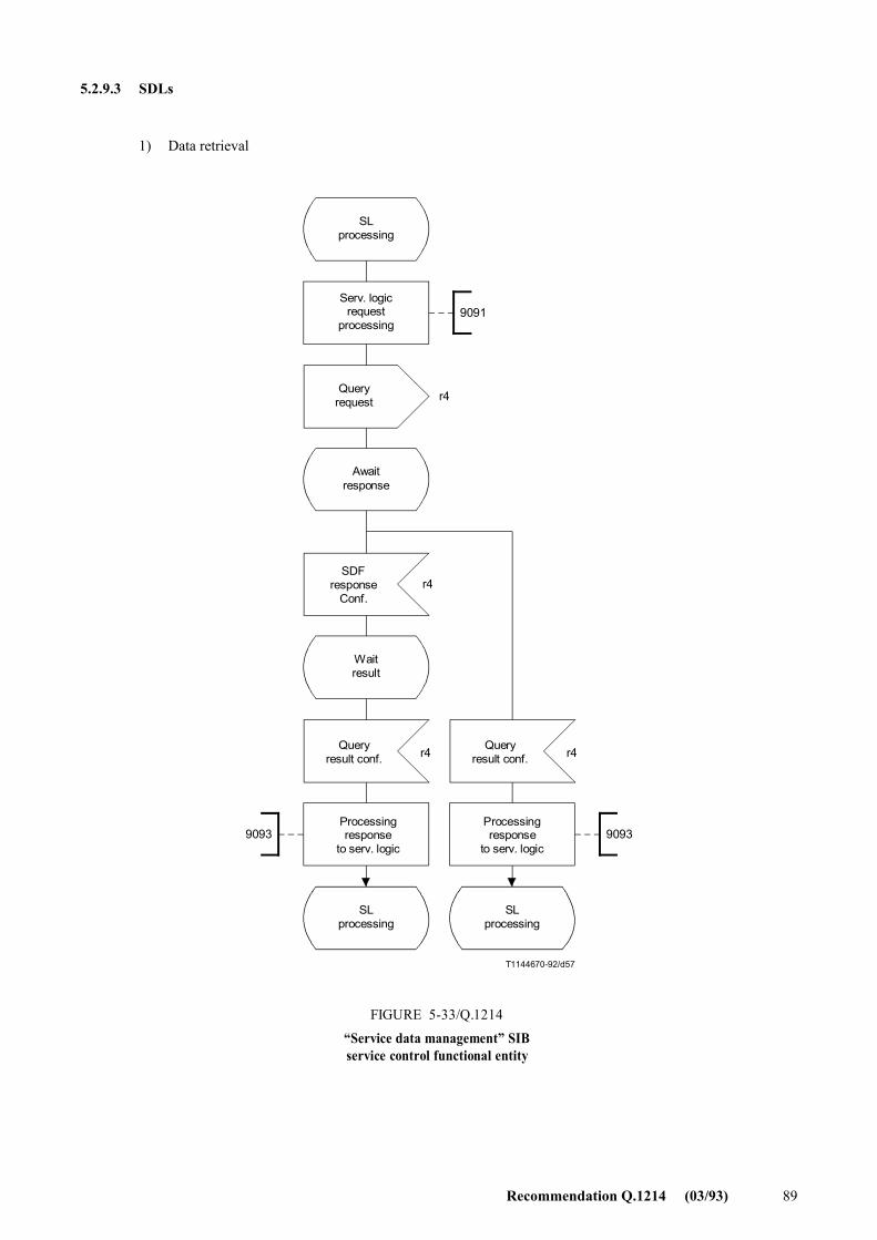
Recommendation Q.1214 (03/93) 89
5.2.9.3 SDLs
1) Data retrieval
T1144670-92/d57
9093 9093
9091
r4
r4
r4 r4
SLprocessing
Serv. logicrequest
processing
Queryrequest
Awaitresponse
Queryresult conf.
SLprocessing
FIGURE 5-33/Q.1214�Service data management� SIBservice control functional entity
SLprocessing
SDFresponse
Conf.
Waitresult
Queryresult conf.
Processingresponse
to serv. logic
Processingresponse
to serv. logic
FIGURE 5-33/Q.1214...[D57] = 21 CM PAGE PLEINE
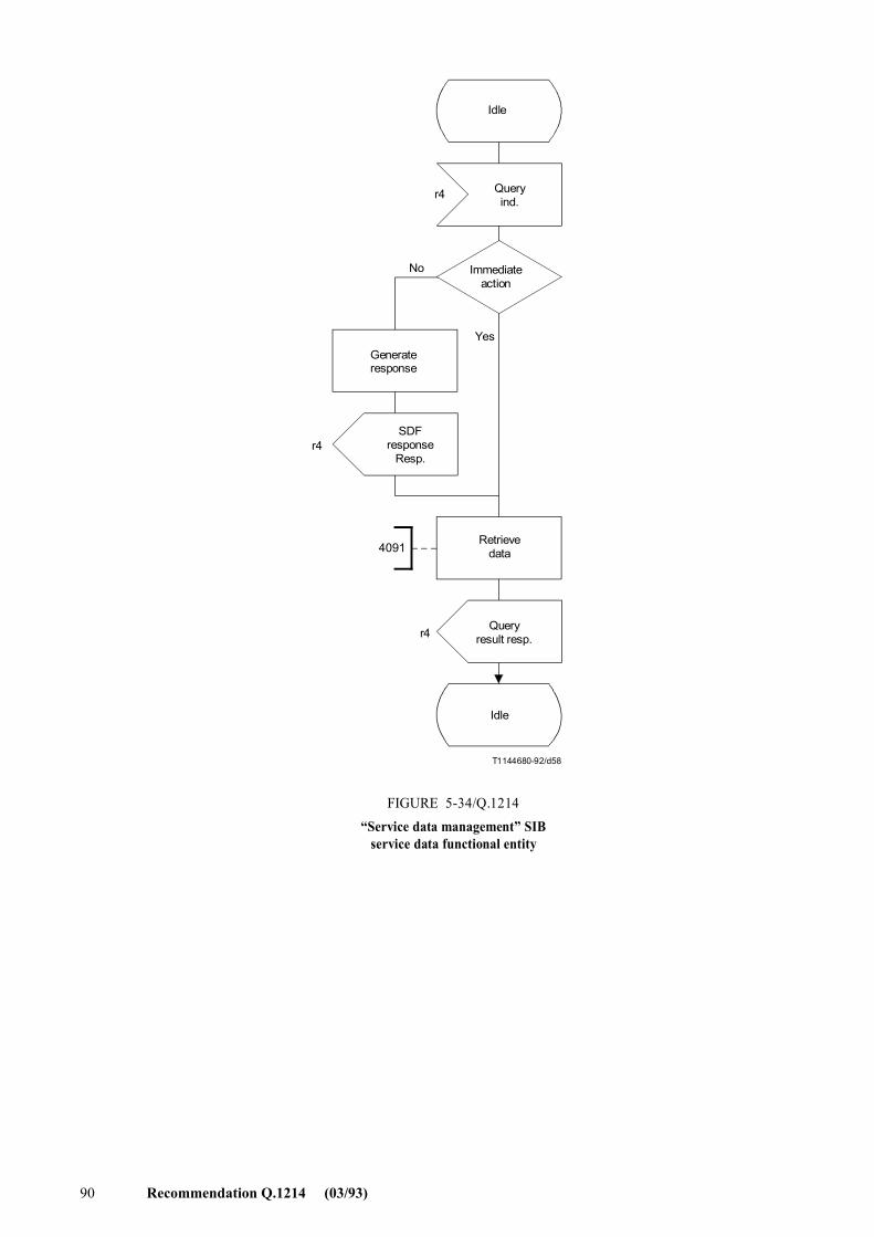
90 Recommendation Q.1214 (03/93)
T1144680-92/d58
4091
r4
r4
r4
Idle
Queryind.
Immediateaction
Queryresult resp.
FIGURE 5-34/Q.1214�Service data management� SIB
service data functional entity
SDFresponse
Resp.
Retrievedata
Idle
No
YesGenerateresponse
FIGURE 5-34/Q.1214...[D58] = 18.5 CM
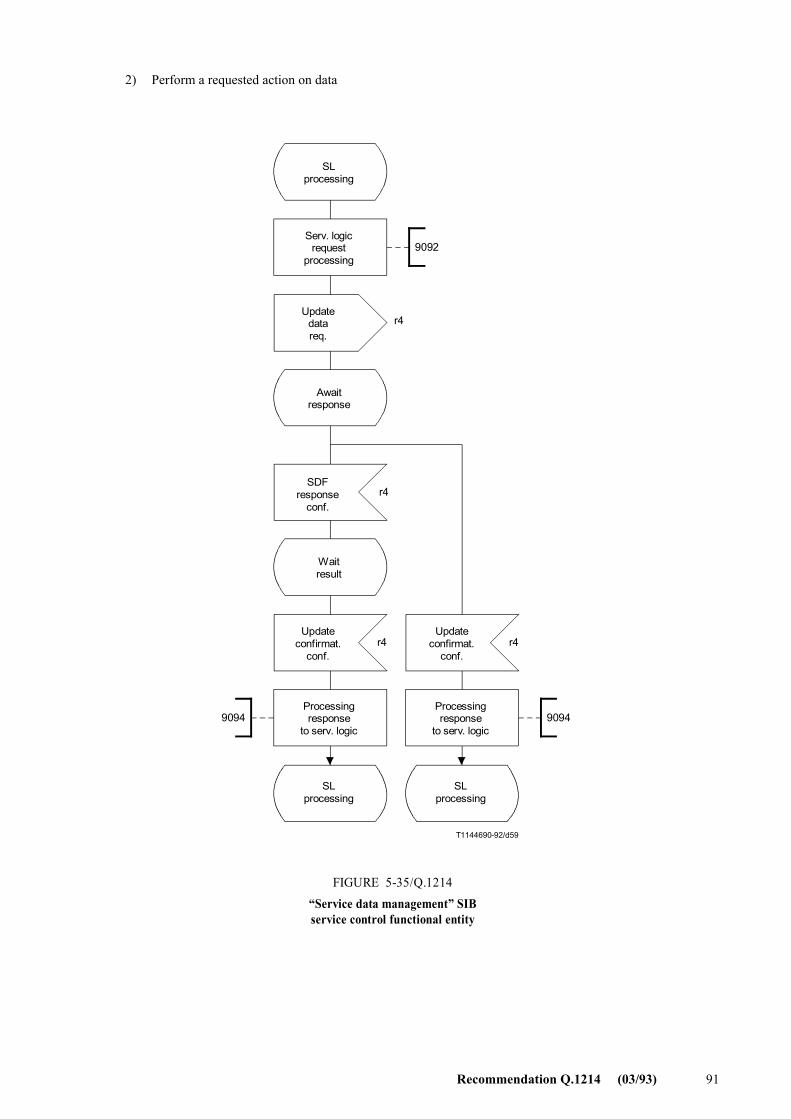
Recommendation Q.1214 (03/93) 91
2) Perform a requested action on data
T1144690-92/d59
9092
90949094
r4
r4
r4 r4
SLprocessing
Serv. logicrequest
processing
Updatedatareq.
Awaitresponse
Updateconfirmat.
conf.
SLprocessing
FIGURE 5-35/Q.1214�Service data management� SIBservice control functional entity
SLprocessing
SDFresponse
conf.
Waitresult
Processingresponse
to serv. logic
Processingresponse
to serv. logic
Updateconfirmat.
conf.
FIGURE 5-35/Q.1214...[D59] = 21 CM PAGE PLEINE
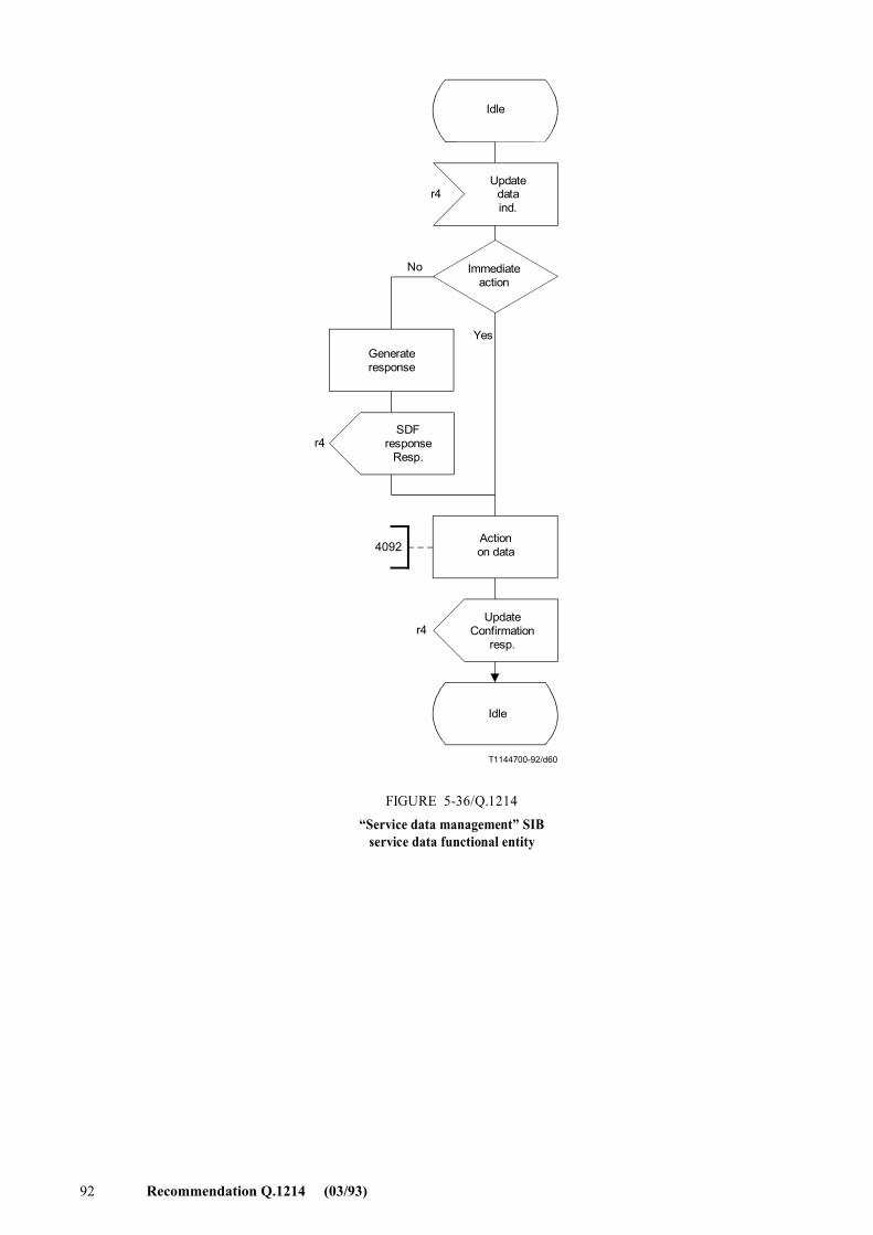
92 Recommendation Q.1214 (03/93)
T1144700-92/d60
4092
r4
r4
r4
Idle
Updatedataind.
Immediateaction
UpdateConfirmation
resp.
FIGURE 5-36/Q.1214�Service data management� SIB
service data functional entity
SDFresponse
Resp.
Actionon data
Idle
No
YesGenerateresponse
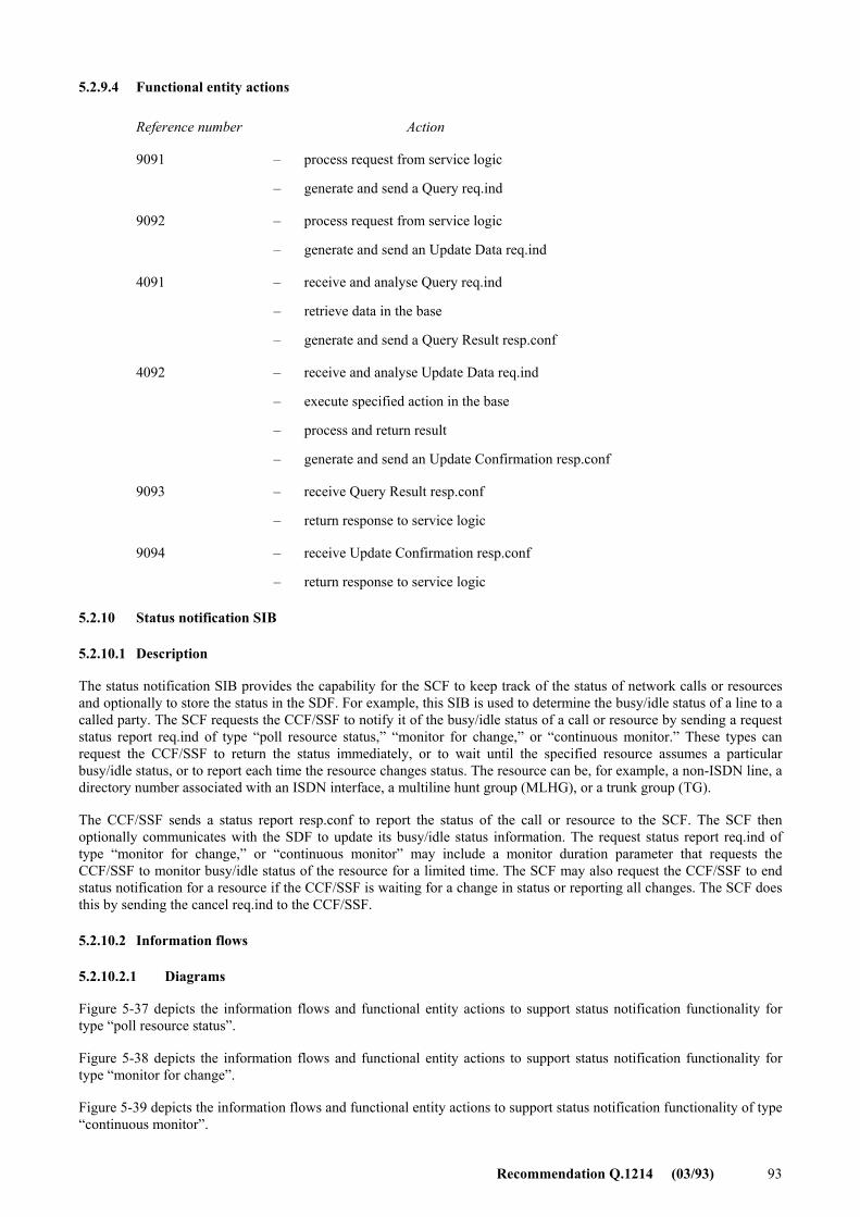
Recommendation Q.1214 (03/93) 93
5.2.9.4 Functional entity actions
Reference number Action
9091 � process request from service logic
� generate and send a Query req.ind
9092 � process request from service logic
� generate and send an Update Data req.ind
4091 � receive and analyse Query req.ind
� retrieve data in the base
� generate and send a Query Result resp.conf
4092 � receive and analyse Update Data req.ind
� execute specified action in the base
� process and return result
� generate and send an Update Confirmation resp.conf
9093 � receive Query Result resp.conf
� return response to service logic
9094 � receive Update Confirmation resp.conf
� return response to service logic
5.2.10 Status notification SIB
5.2.10.1 Description
The status notification SIB provides the capability for the SCF to keep track of the status of network calls or resources and optionally to store the status in the SDF. For example, this SIB is used to determine the busy/idle status of a line to a called party. The SCF requests the CCF/SSF to notify it of the busy/idle status of a call or resource by sending a request status report req.ind of type �poll resource status,� �monitor for change,� or �continuous monitor.� These types can request the CCF/SSF to return the status immediately, or to wait until the specified resource assumes a particular busy/idle status, or to report each time the resource changes status. The resource can be, for example, a non-ISDN line, a directory number associated with an ISDN interface, a multiline hunt group (MLHG), or a trunk group (TG).
The CCF/SSF sends a status report resp.conf to report the status of the call or resource to the SCF. The SCF then optionally communicates with the SDF to update its busy/idle status information. The request status report req.ind of type �monitor for change,� or �continuous monitor� may include a monitor duration parameter that requests the CCF/SSF to monitor busy/idle status of the resource for a limited time. The SCF may also request the CCF/SSF to end status notification for a resource if the CCF/SSF is waiting for a change in status or reporting all changes. The SCF does this by sending the cancel req.ind to the CCF/SSF.
5.2.10.2 Information flows
5.2.10.2.1 Diagrams
Figure 5-37 depicts the information flows and functional entity actions to support status notification functionality for type �poll resource status�.
Figure 5-38 depicts the information flows and functional entity actions to support status notification functionality for type �monitor for change�.
Figure 5-39 depicts the information flows and functional entity actions to support status notification functionality of type �continuous monitor�.
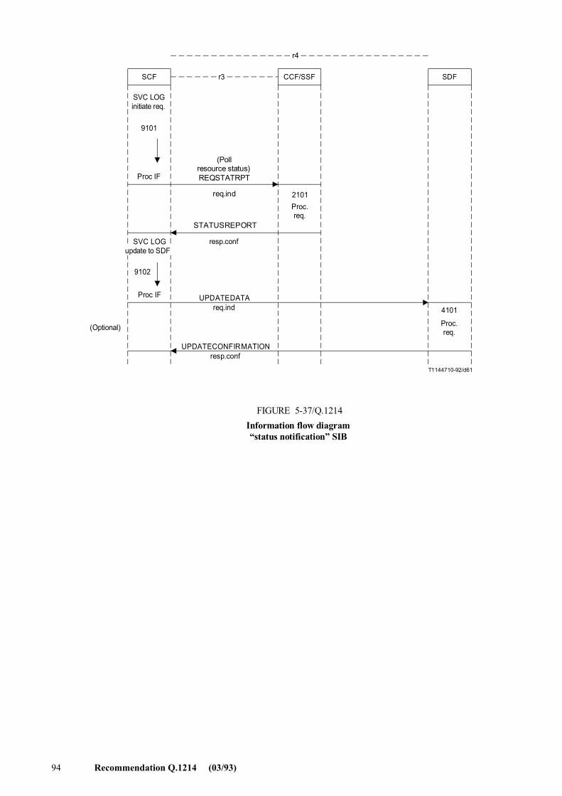
94 Recommendation Q.1214 (03/93)
T1144710-92/d61
CCF/SSFr3SCF SDF
r4
SVC LOGinitiate req.
9101
Proc IF
Proc IF
9102
(Optional)
(Pollresource status)REQSTATRPT
2101Proc.req.
4101
Proc.req.
resp.conf
FIGURE 5-37/Q.1214Information flow diagram�status notification� SIB
UPDATECONFIRMATIONresp.conf
UPDATEDATAreq.ind
SVC LOGupdate to SDF
req.ind
STATUSREPORT
FIGURE 5-37/Q.1214...[D61] = 14.5 CM
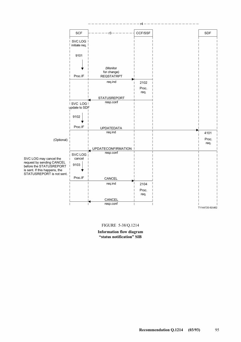
Recommendation Q.1214 (03/93) 95
T1144720-92/d62
CCF/SSFr3SCF SDF
r4
SVC LOGinitiate req.
9101
Proc.IF
9102
Proc.IF
2102
Proc.req.
4101
Proc.req.
(Optional)
SVC LOGcancel
9103
Proc.IF
SVC LOG may cancel therequest by sending CANCELbefore the STATUSREPORTis sent. If this happens, theSTATUSREPORT is not sent.
req.ind 2104
Proc.req.
FIGURE 5-38/Q.1214Information flow diagram�status notification� SIB
STATUSREPORTresp.conf
UPDATEDATAreq.ind
UPDATECONFIRMATIONresp.conf
(Monitorfor change)
req.ind
REQSTATRPT
CANCELresp.conf
SVC LOGupdate to SDF
CANCEL
FIGURE 5-38/Q.1214...[D62] = 18.5 CM
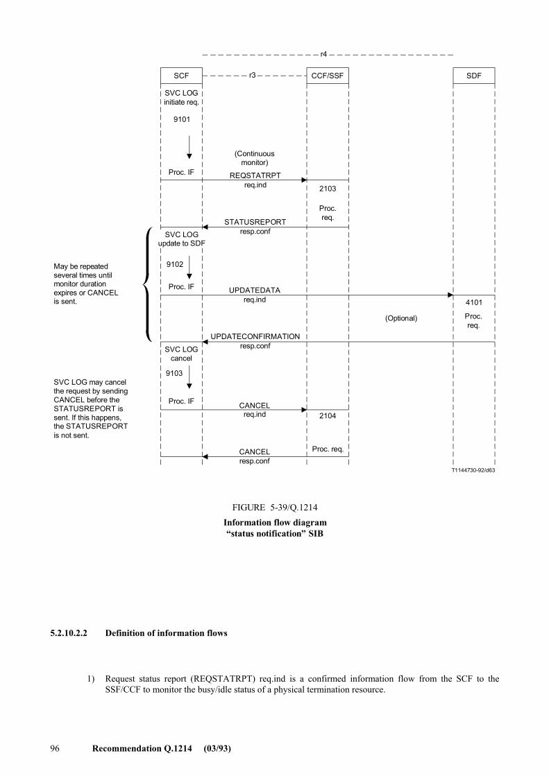
96 Recommendation Q.1214 (03/93)
T1144730-92/d63
CCF/SSFr3SCF SDF
r4
SVC LOGinitiate req.
9101
Proc. IF
SVC LOGupdate to SDF
9102
Proc. IF
(Optional)
4101
Proc.req.
2103
Proc.req.
SVC LOGcancel
9103
Proc. IF
2104
Proc. req.
May be repeatedseveral times untilmonitor durationexpires or CANCELis sent.
SVC LOG may cancelthe request by sendingCANCEL before theSTATUSREPORT issent. If this happens,the STATUSREPORTis not sent.
FIGURE 5-39/Q.1214Information flow diagram�status notification� SIB
STATUSREPORTresp.conf
UPDATEDATA req.ind
UPDATECONFIRMATIONresp.conf
CANCELreq.ind
CANCELresp.conf
(Continuousmonitor)
REQSTATRPTreq.ind
FIGURE 5-39/Q.1214...[D63] = 18.5 CM
5.2.10.2.2 Definition of information flows
1) Request status report (REQSTATRPT) req.ind is a confirmed information flow from the SCF to the SSF/CCF to monitor the busy/idle status of a physical termination resource.
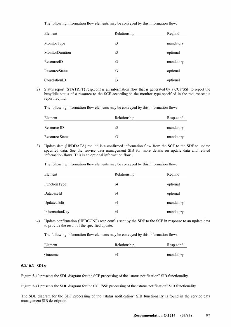
Recommendation Q.1214 (03/93) 97
The following information flow elements may be conveyed by this information flow:
Element Relationship Req.ind
MonitorType r3 mandatory
MonitorDuration r3 optional
ResourceID r3 mandatory
ResourceStatus r3 optional
CorrelationID r3 optional
2) Status report (STATRPT) resp.conf is an information flow that is generated by a CCF/SSF to report the busy/idle status of a resource to the SCF according to the monitor type specified in the request status report req.ind.
The following information flow elements may be conveyed by this information flow:
Element Relationship Resp.conf
Resource ID r3 mandatory
Resource Status r3 mandatory
3) Update data (UPDDATA) req.ind is a confirmed information flow from the SCF to the SDF to update specified data. See the service data management SIB for more details on update data and related information flows. This is an optional information flow.
The following information flow elements may be conveyed by this information flow:
Element Relationship Req.ind
FunctionType r4 optional
DatabaseId r4 optional
UpdatedInfo r4 mandatory
InformationKey r4 mandatory
4) Update confirmation (UPDCONF) resp.conf is sent by the SDF to the SCF in response to an update data to provide the result of the specified update.
The following information flow elements may be conveyed by this information flow:
Element Relationship Resp.conf
Outcome r4 mandatory
5.2.10.3 SDLs
Figure 5-40 presents the SDL diagram for the SCF processing of the �status notification� SIB functionality.
Figure 5-41 presents the SDL diagram for the CCF/SSF processing of the �status notification� SIB functionality.
The SDL diagram for the SDF processing of the �status notification� SIB functionality is found in the service data management SIB description.
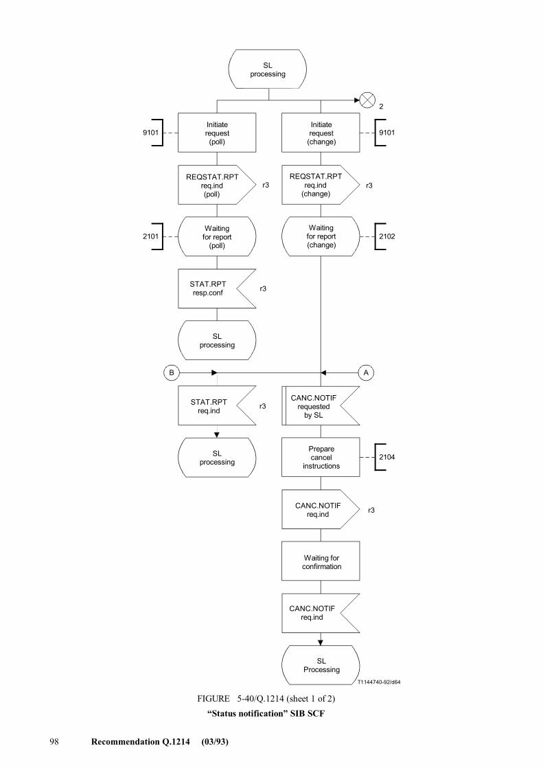
98 Recommendation Q.1214 (03/93)
T1144740-92/d64
B A
9101
2102
2104
9101
2
2101
r3
r3r3
r3
r3
SLprocessing
Initiaterequest(poll)
Initiaterequest
(change)
REQSTAT.RPTreq.ind(poll)
REQSTAT.RPTreq.ind
(change)
Waitingfor report
(poll)
Waitingfor report(change)
STAT.RPTresp.conf
SLprocessing
STAT.RPTreq.ind
SLprocessing
CANC.NOTIFrequested
by SL
Preparecancel
instructions
CANC.NOTIFreq.ind
Waiting forconfirmation
CANC.NOTIFreq.ind
SLProcessing
FIGURE 5-40/Q.1214 (sheet 1 of 2)�Status notification� SIB SCF
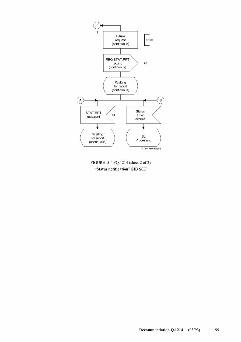
Recommendation Q.1214 (03/93) 99
9101
A B
T1144750-92/d65
1
r3
r3
Initiaterequest
(continuous)
REQ.STAT.RPTreq.ind
(continuous)
Waitingfor report
(continuous)
STAT.RPTresp.conf
Waitingfor report
(continuous)
SLProcessing
Statustimer
expires
FIGURE 5-40/Q.1214 (sheet 2 of 2)�Status notification� SIB SCF
FIGURE 5-40/Q.1214...[D65] = 13 CM
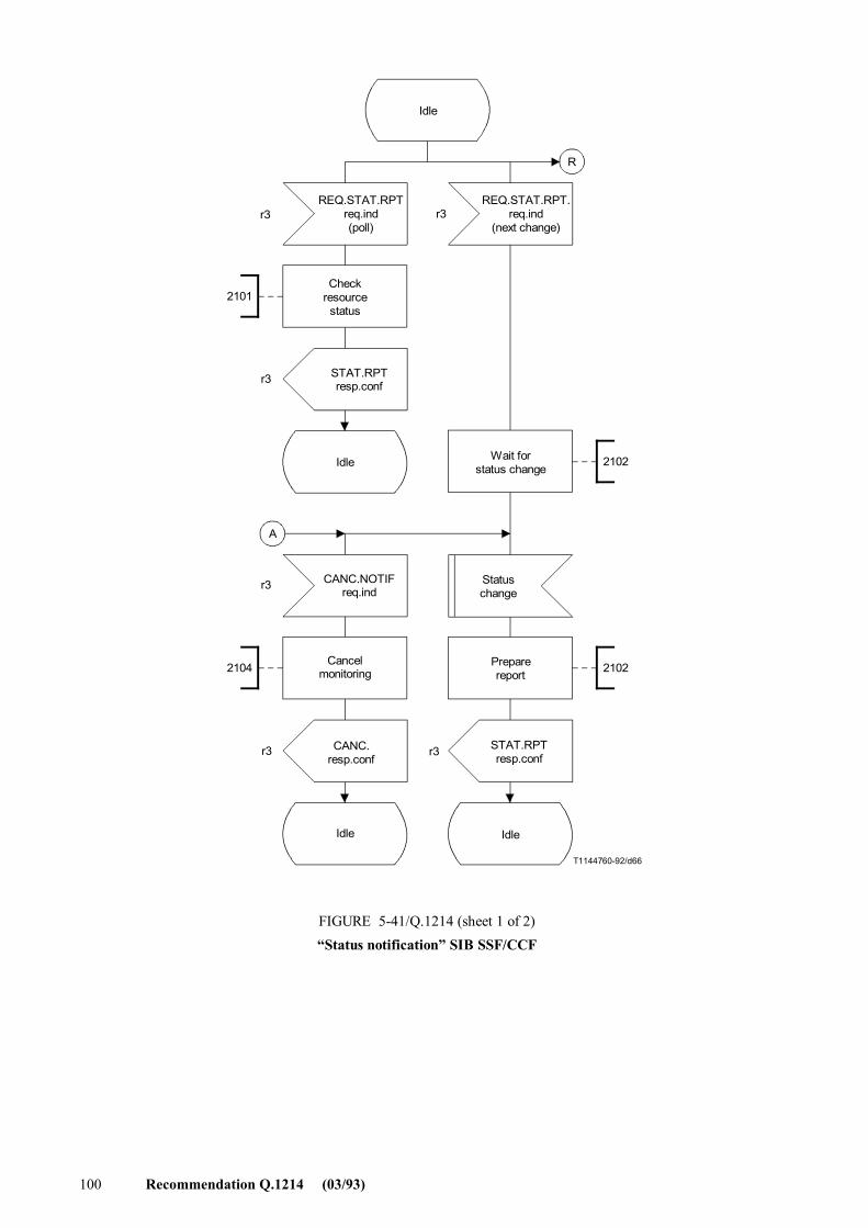
100 Recommendation Q.1214 (03/93)
T1144760-92/d66
R
A
2104
2101
2102
2102
r3r3
r3
r3
r3 r3
Idle
REQ.STAT.RPTreq.ind(poll)
REQ.STAT.RPT.req.ind
(next change)
Checkresource
status
STAT.RPTresp.conf
Idle Wait forstatus change
CANC.NOTIFreq.ind
Cancelmonitoring
CANC.resp.conf
Idle
Statuschange
Preparereport
STAT.RPTresp.conf
Idle
FIGURE 5-41/Q.1214 (sheet 1 of 2)�Status notification� SIB SSF/CCF
FIGURE 5-41/Q.1214...[D66] = 21 CM PLEINE PAGE
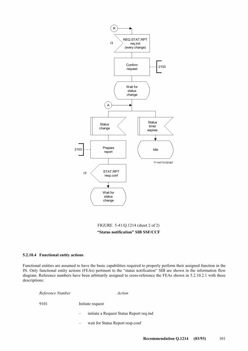
Recommendation Q.1214 (03/93) 101
2103
2103
R
T1144770-92/d67
A
r3
r3
REQ.STAT.RPTreq.ind
(every change)
Confirmrequest
Wait forstatuschange
Statuschange
Preparereport
STAT.RPTresp.conf
Wait forstatuschange
Statustimer
expires
Idle
FIGURE 5-41/Q.1214 (sheet 2 of 2)�Status notification� SIB SSF/CCF
FIGURE 5-41/Q.1214...[D67] = 17.5 CM
5.2.10.4 Functional entity actions
Functional entities are assumed to have the basic capabilities required to properly perform their assigned function in the IN. Only functional entity actions (FEAs) pertinent to the �status notification� SIB are shown in the information flow diagram. Reference numbers have been arbitrarily assigned to cross-reference the FEAs shown in 5.2.10.2.1 with these descriptions:
Reference Number Action
9101 Initiate request
� initiate a Request Status Report req.ind
� wait for Status Report resp.conf
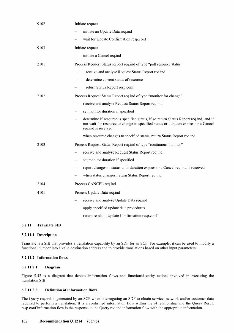
102 Recommendation Q.1214 (03/93)
9102 Initiate request
� initiate an Update Data req.ind
� wait for Update Confirmation resp.conf
9103 Initiate request
� initiate a Cancel req.ind
2101 Process Request Status Report req.ind of type �poll resource status�
� receive and analyse Request Status Report req.ind
� determine current status of resource
� return Status Report resp.conf
2102 Process Request Status Report req.ind of type �monitor for change�
� receive and analyse Request Status Report req.ind
� set monitor duration if specified
� determine if resource is specified status, if so return Status Report req.ind, and if not wait for resource to change to specified status or duration expires or a Cancel req.ind is received
� when resource changes to specified status, return Status Report req.ind
2103 Process Request Status Report req.ind of type �continuous monitor�
� receive and analyse Request Status Report req.ind
� set monitor duration if specified
� report changes in status until duration expires or a Cancel req.ind is received
� when status changes, return Status Report req.ind
2104 Process CANCEL req.ind
4101 Process Update Data req.ind
� receive and analyse Update Data req.ind
� apply specified update data procedures
� return result in Update Confirmation resp.conf
5.2.11 Translate SIB
5.2.11.1 Description
Translate is a SIB that provides a translation capability by an SDF for an SCF. For example, it can be used to modify a functional number into a valid destination address and to provide translations based on other input parameters.
5.2.11.2 Information flows
5.2.11.2.1 Diagram
Figure 5-42 is a diagram that depicts information flows and functional entity actions involved in executing the translation SIB.
5.2.11.2.2 Definition of information flows
The Query req.ind is generated by an SCF when interrogating an SDF to obtain service, network and/or customer data required to perform a translation. It is a confirmed information flow within the r4 relationship and the Query Result resp.conf information flow is the response to the Query req.ind information flow with the appropriate information.
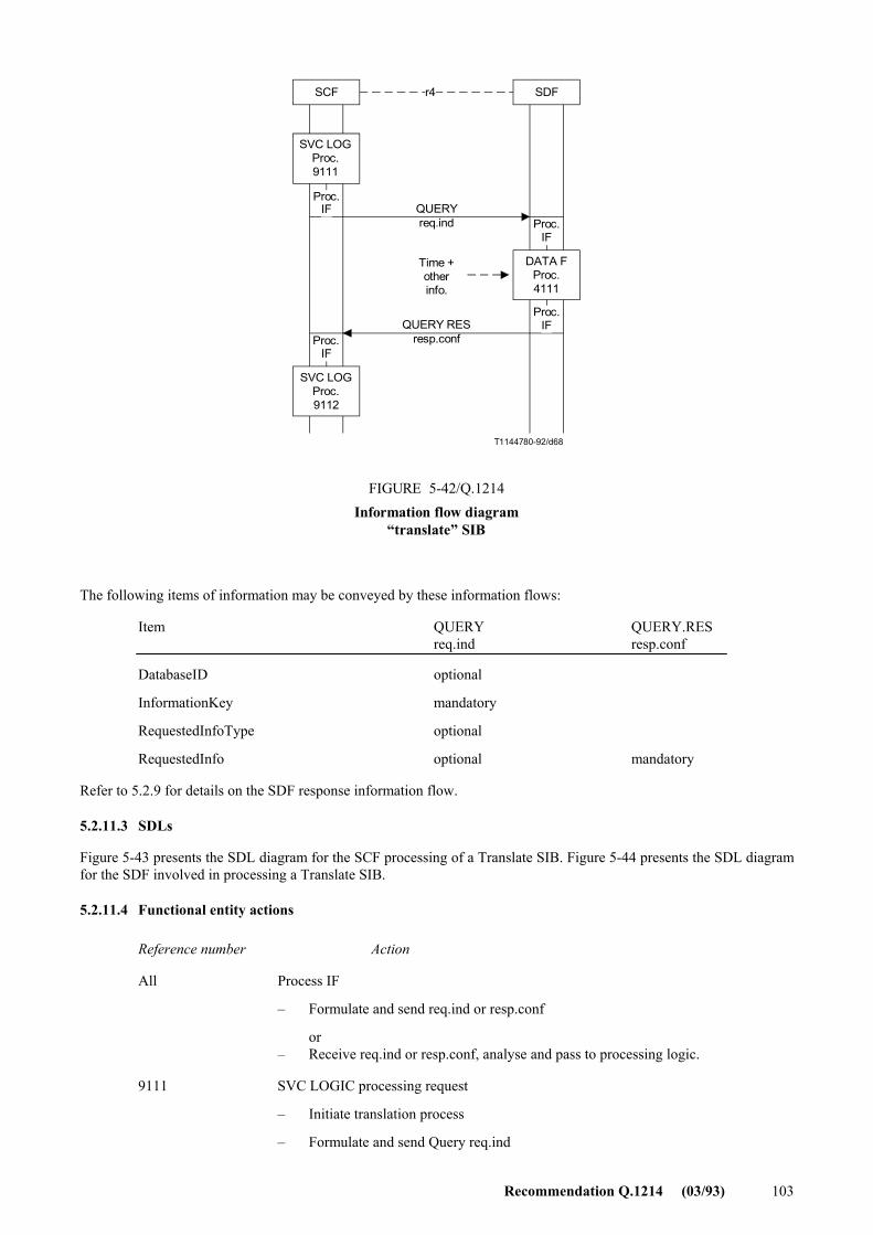
Recommendation Q.1214 (03/93) 103
T1144780-92/d68
SCF SDFr4
SVC LOGProc.9111
QUERYreq.ind
DATA FProc.4111
Time +otherinfo.
QUERY RESresp.conf
SVC LOGProc.9112
FIGURE 5-42/Q.1214Information flow diagram
�translate� SIB
Proc.IF
Proc.IF
Proc.IF
Proc.IF
FIGURE 5-42/Q.1214...[D68] = 10.5 CM
The following items of information may be conveyed by these information flows:
Item QUERY QUERY.RES req.ind resp.conf
DatabaseID optional
InformationKey mandatory
RequestedInfoType optional
RequestedInfo optional mandatory
Refer to 5.2.9 for details on the SDF response information flow.
5.2.11.3 SDLs
Figure 5-43 presents the SDL diagram for the SCF processing of a Translate SIB. Figure 5-44 presents the SDL diagram for the SDF involved in processing a Translate SIB.
5.2.11.4 Functional entity actions
Reference number Action
All Process IF
� Formulate and send req.ind or resp.conf
or � Receive req.ind or resp.conf, analyse and pass to processing logic.
9111 SVC LOGIC processing request
� Initiate translation process
� Formulate and send Query req.ind
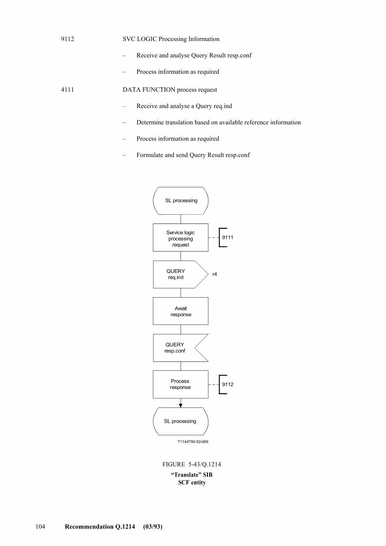
104 Recommendation Q.1214 (03/93)
9112 SVC LOGIC Processing Information
� Receive and analyse Query Result resp.conf
� Process information as required
4111 DATA FUNCTION process request
� Receive and analyse a Query req.ind
� Determine translation based on available reference information
� Process information as required
� Formulate and send Query Result resp.conf
T1144790-92/d69
9111
9112
r4
SL processing
Service logicprocessing
request
QUERYreq.ind
Awaitresponse
QUERYresp.conf
FIGURE 5-43/Q.1214�Translate� SIB
SCF entity
Processresponse
SL processing
FIGURE 5-43/Q.1214...[D69] = 16.5 CM
Recommendation Q.1214 (03/93) 105
T1144800-92/d70
4111
r4
r4
Idle
QUERYreq.ind
Processtranslaterequest
QUERYresp.conf
Idle
FIGURE 5-44/Q.1214�Translate� SIB
SDF entity
FIGURE 5-44/Q.1214...[D70] = 12.5 CM
5.2.12 User interaction SIB
5.2.12.1 Description
User interaction is a SIB wherein the SCF directs the connection of a user to a specialized resource (i.e. SRF), the playing of an announcement toward and, in some cases, the collection of information from a user. The announcement and/or collected information can be in the form of audio messages, DTMF tones, etc.
5.2.12.2 Information flows
5.2.12.2.1 Diagrams
Figures 5-45 and 5-46 depict information flows and functional entity actions involved in executing the user interaction SIB for playing an announcement and/or obtaining additional information from a user over the bearer channel, e.g. 64 kbit/s circuit. Execution of the user interaction SIB to interact with an ISDN user via his D-channel is for further study.
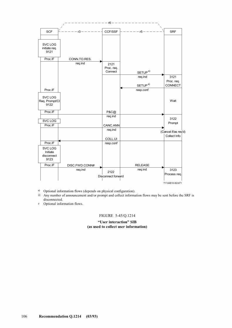
106 Recommendation Q.1214 (03/93)
r5
T1144810-92/d71
CCF/SSFr3SCF SRF
r6
SVC LOGinitiate req.
9121
Proc.IF
Proc.IF
SVC LOGReq. Prompt/CI
9122
2121Proc. req.Connect
CONN.TO.RES.req.ind
SETUPreq.ind
SETUPresp.conf
3121Proc. req.
CONNECT
Wait
Proc.IF
SVC LOGProc.IF
Proc.IF
SVC LOGInitiate
disconnect9123
Proc.IF DISC.FWD.CONN#req.ind
RELEASEreq.ind
CANC.ANNreq.ind
COLL.UIresp.conf
3122Prompt
3123Process req.
FIGURE 5-45/Q.1214�User interaction� SIB
(as used to collect user information)
a)
a)
Optional information flows (depends on physical configuration).Any number of announcement and/or prompt and collect information flows may be sent before the SRF isdisconnected.Optional information flows.
a)
@
#
(Cancel if/as req'd)Collect Info
2122Disconnect forward
FIGURE 5-45/Q.1214...[D71] = 19 CM
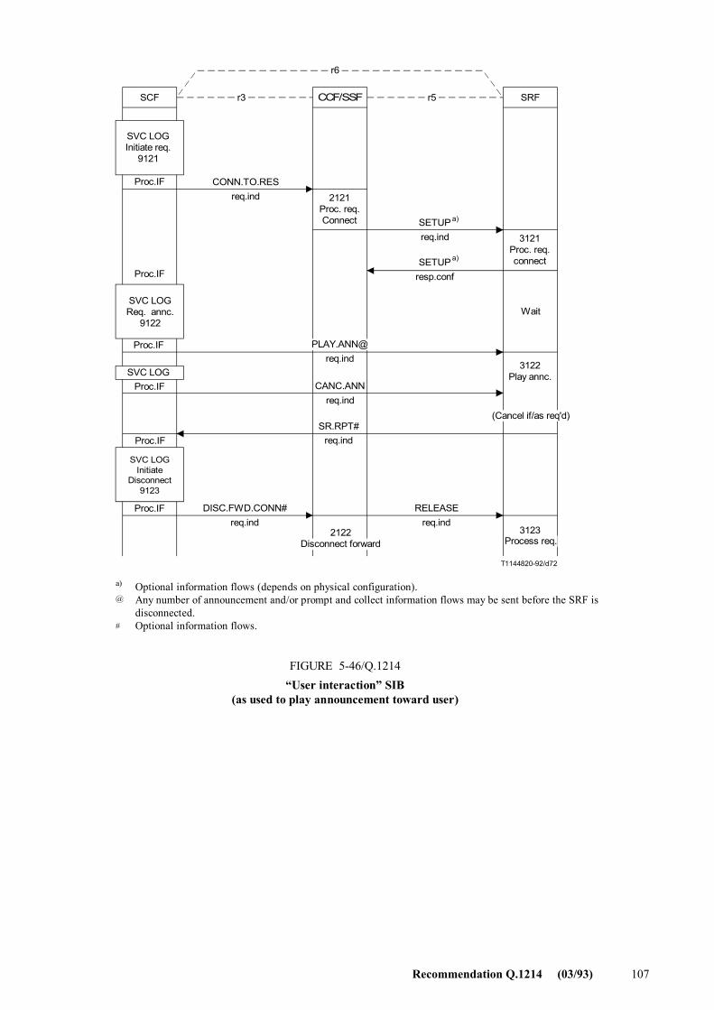
Recommendation Q.1214 (03/93) 107
r5
T1144820-92/d72
CCF/SSFr3SCF SRF
r6
SVC LOGInitiate req.
9121
Proc.IF
SVC LOGReq. annc.
9122
Proc.IF
2121Proc. req.Connect
3121Proc. req.connect
CONN.TO.RESreq.ind
SETUPreq.ind
SETUPresp.conf
Wait
SVC LOG3122
Play annc.
(Cancel if/as req'd)
SVC LOGInitiate
Disconnect9123
DISC.FWD.CONN#req.ind
RELEASEreq.ind
FIGURE 5-46/Q.1214�User interaction� SIB
(as used to play announcement toward user)
Proc.IF
Proc.IF
Proc.IF
Proc.IF
CANC.ANNreq.ind
SR.RPT#req.ind
a)
a)
Optional information flows (depends on physical configuration).Any number of announcement and/or prompt and collect information flows may be sent before the SRF isdisconnected.Optional information flows.
3123Process req.
2122Disconnect forward
a)
@
#
FIGURE 5-46/Q.1214...[D72] = 19 CM
108 Recommendation Q.1214 (03/93)
5.2.12.2.2 Definition of information flows
1) Connect To Resource req.ind is an unconfirmed information flow used by the SCF to request that the CCF/SSF extend a connection toward an SRF so that interaction with the end user can take place. This information flow occurs in the r3 relationship and contains the following items of information:
Item CONN.TO.RES. req.ind
Call ID mandatory
IP Routing address optional
Party ID optional
2) Setup req.ind is a confirmed information flow that is defined in Recommendation Q.71 for ISDN basic call setup. It occurs in the r5 relationship and carries the items of information required by the SRF to establish an appropriate connection to the proper SRF termination(s). Setup resp.conf confirms to the CCF/SSF that the SRF has established the required connection(s).
NOTE � Use of the ISDN basic call setup information flow does not imply that the SRF-to-CCF/SSF interface needs to be ISDN.
3) Prompt And Collect User Information req.ind is a confirmed information flow initiated by the SCF to an SRF to request that the required prompt/announcement be applied on the connection toward a call party and that information from the call party be received and returned to the SCF. The Collected User Information resp.conf conveys this information to the SCF. These information flows occur in the r6 relationship and convey the following items of information:
Item P&C COLL.UI req.ind resp.conf
SRF Connect ID mandatory mandatory
Information To Send mandatory
Disconnection from IP Forbidden mandatory
Collected Info Format Received info mandatory mandatory
4) Play Announcement req.ind is an optionally confirmed information flow initiated by an SCF to an SRF to direct that a specific announcement be applied on the connection toward the call party. The SRF Report is sent from the SRF back to the SCF at the end of playing the announcement. These information flows occur in the r6 relationship and contain the following items of information:
Item PLAY.ANN SRF.RPT req.ind resp.conf
SRF Connect ID mandatory mandatory
Information To Send mandatory
Disconnection from IP Forbidden mandatory
Request Ann. Completed Indication mandatory
Recommendation Q.1214 (03/93) 109
5) Cancel Announcement req.ind is an unconfirmed information flow in the r6 relationship wherein the SCF directs the SRF to discontinue playing an announcement to a call party.
Item CANC.ANN req.ind
Operation identifier mandatory
6) Disconnect Forward Connection req.ind is an information flow in the r3 relationship initiated by the SCF to direct the CCF/SSF to initiate disconnection of the SRF from the connection toward the user. In the case of service assist it is also used to clear the connection between the Assisting SSF and the Initiating SSF.
Item DISC.FWD.CONN req.ind
SRF Connect ID mandatory
7) Disconnect req.ind is a confirmed information flow that is defined in Recommendation Q.71 for ISDN basic call setup. It occurs in the r5 relationship and carries the items of information required by the SRF to release a connection to the specified SRF termination(s).
5.2.12.3 SDLs
Figure 5-47 is an SDL that shows the actions at an SCF involved in executing the user interaction SIB.
Figure 5-48 is an SDL that shows the actions at a CCF/SSF involved in executing the user interaction SIB.
Figure 5-49 is an SDL that shows the actions at an SRF involved in executing the user interaction SIB.
5.2.12.4 Functional entity actions
Reference number Action
All Process IF (IF = Information flow)
� React to service logic to formulate and send a req.ind or resp.conf, or
� Receive req.ind or resp.conf and pass to service logic
9121 Initiate request
� Initiate a CONN.TO.RES req.ind
9122 Request Prompt/Collect Information or Announcement
� Initiate a P&C or PLAY.ANN req.ind and send to the SRF
9123 Initiate disconnect
� Initiate a DISC.FWD.CONN req.ind and send to the CCF/SSF
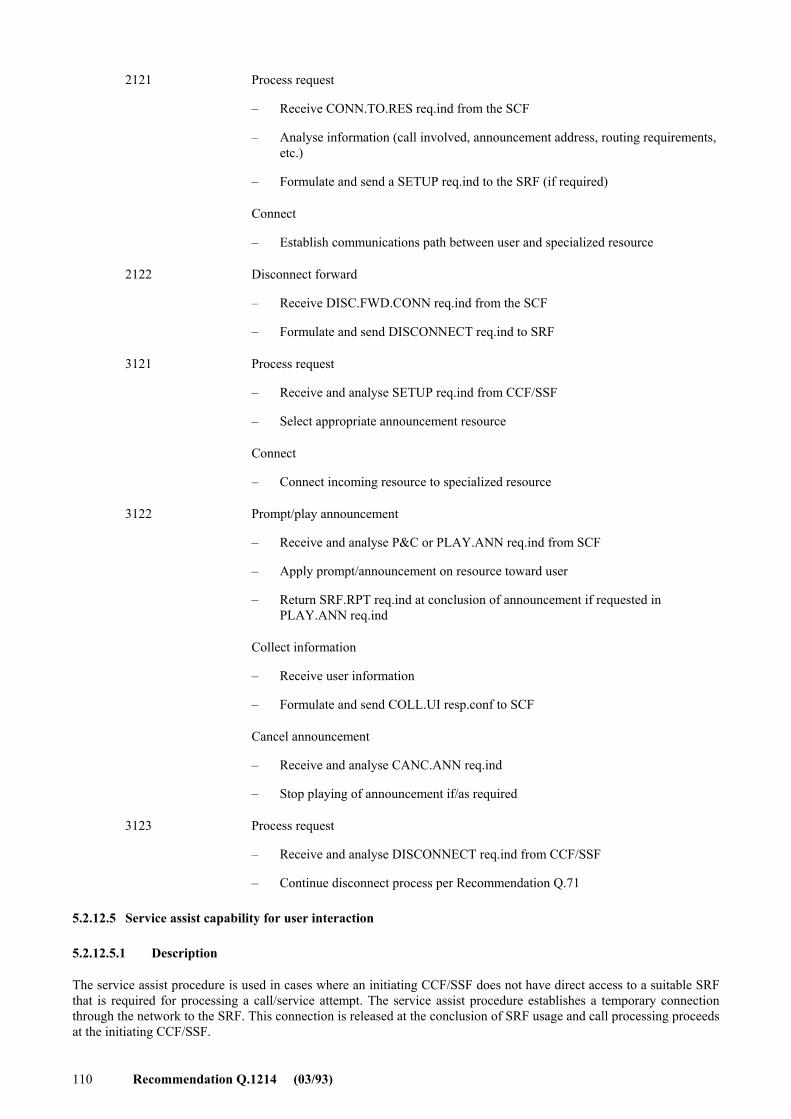
110 Recommendation Q.1214 (03/93)
2121 Process request
� Receive CONN.TO.RES req.ind from the SCF
� Analyse information (call involved, announcement address, routing requirements, etc.)
� Formulate and send a SETUP req.ind to the SRF (if required)
Connect
� Establish communications path between user and specialized resource
2122 Disconnect forward
� Receive DISC.FWD.CONN req.ind from the SCF
� Formulate and send DISCONNECT req.ind to SRF
3121 Process request
� Receive and analyse SETUP req.ind from CCF/SSF
� Select appropriate announcement resource
Connect
� Connect incoming resource to specialized resource
3122 Prompt/play announcement
� Receive and analyse P&C or PLAY.ANN req.ind from SCF
� Apply prompt/announcement on resource toward user
� Return SRF.RPT req.ind at conclusion of announcement if requested in PLAY.ANN req.ind
Collect information
� Receive user information
� Formulate and send COLL.UI resp.conf to SCF
Cancel announcement
� Receive and analyse CANC.ANN req.ind
� Stop playing of announcement if/as required
3123 Process request
� Receive and analyse DISCONNECT req.ind from CCF/SSF
� Continue disconnect process per Recommendation Q.71
5.2.12.5 Service assist capability for user interaction
5.2.12.5.1 Description
The service assist procedure is used in cases where an initiating CCF/SSF does not have direct access to a suitable SRF that is required for processing a call/service attempt. The service assist procedure establishes a temporary connection through the network to the SRF. This connection is released at the conclusion of SRF usage and call processing proceeds at the initiating CCF/SSF.
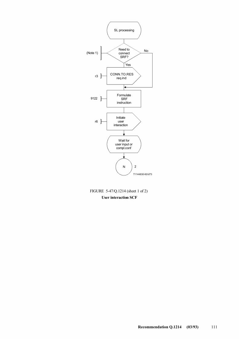
Recommendation Q.1214 (03/93) 111
T1144830-92/d73
r3
9122
r6
N 2
SL processing
Need toconnectSRF?
(Note 1) No
Yes
CONN.TO.RESreq.ind
FormulateSRF
instruction
Initiateuser
interaction
Wait foruser input orcompl.conf
FIGURE 5-47/Q.1214 (sheet 1 of 2)User interaction SCF
FIGURE 5-47/Q.1214...[D73] = 15.5 CM
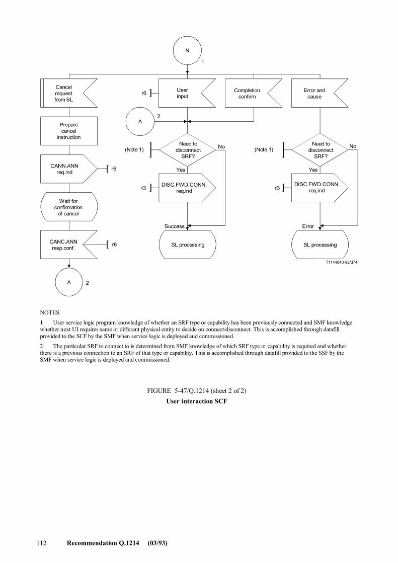
112 Recommendation Q.1214 (03/93)
T1144840-92/d74
N
A
A
r6
r6
2
r3
r6
r3
2
1
Cancelrequestfrom SL
Preparecancel
instruction
CANN.ANNreq.ind
Wait forconfirmation
of cancel
Userinput
Completionconfirm
Error andcause
Need todisconnect
SRF?
DISC.FWD.CONN.req.ind
(Note 1) No No
Yes Yes
SL processingSL processing
ErrorSuccess
(Note 1)
CANC.ANNresp.conf.
FIGURE 5-47/Q.1214 (sheet 2 of 2)User interaction SCF
Need todisconnect
SRF?
DISC.FWD.CONN.req.ind
NOTES
1 User service logic program knowledge of whether an SRF type or capability has been previously connected and SMF knowledge whether next UI requires same or different physical entity to decide on connect/disconnect. This is accomplished through datafill provided to the SCF by the SMF when service logic is deployed and commissioned.
2 The particular SRF to connect to is determined from SMF knowledge of which SRF type or capability is required and whether there is a previous connection to an SRF of that type or capability. This is accomplished through datafill provided to the SSF by the SMF when service logic is deployed and commissioned.
FIGURE 5-47/Q.1214...[D74] = 20 CM PLEINE PAGE
Recommendation Q.1214 (03/93) 113
T1144850-92/d75
r3
r3
2122
2121
DETECTIONPT
wait state
CONN. TO. RES.req.ind
Processrequest and
connect to SRF
Userconnected
to SRF
DISC. FWD. CONN.req.ind
Disconnectforward
DetectionPT
wait state
FIGURE 5-48/Q.1214UI SSF
FIGURE 5-48/Q.1214...[D75] = 163 CM
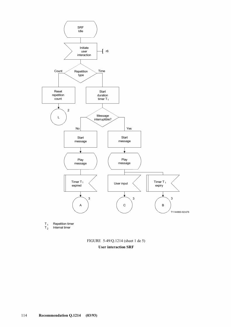
114 Recommendation Q.1214 (03/93)
T1144860-92/d76
L
A C B
r6
2
3 3 3
SRFIdle
Initiateuser
interaction
Repetitiontype
Resetrepetition
count
Startdurationtimer T 1
Messageinterruptible?
Startmessage
Playmessage
Timer Texpired
1 User input Timer Texpiry
1
Count Time
No Yes
T T
12
Repetition timerInternal timer
FIGURE 5-49/Q.1214 (sheet 1 de 5)User interaction SRF
Startmessage
Playmessage
FIGURE 5-49/Q.1214...[D76] = 21 CM PLEINE PAGE
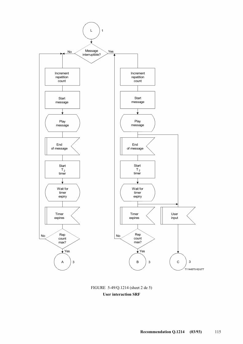
Recommendation Q.1214 (03/93) 115
L
A B C
T1144870-92/d77
3 3 3
1
Messageinterruptible?
No Yes
Incrementrepetition
count
Incrementrepetition
count
Startmessage
Playmessage
End of message
StartT
timer2
StartT
timer2
Wait fortimerexpiry
Timerexpires
Timerexpires
Userinput
Repcountmax?
Repcountmax?
FIGURE 5-49/Q.1214 (sheet 2 de 5)User interaction SRF
No No
Yes Yes
Startmessage
Playmessage
End of message
Wait fortimerexpiry
FIGURE 5-49/Q.1214...[D77] = 24 CM PLEINE PAGE
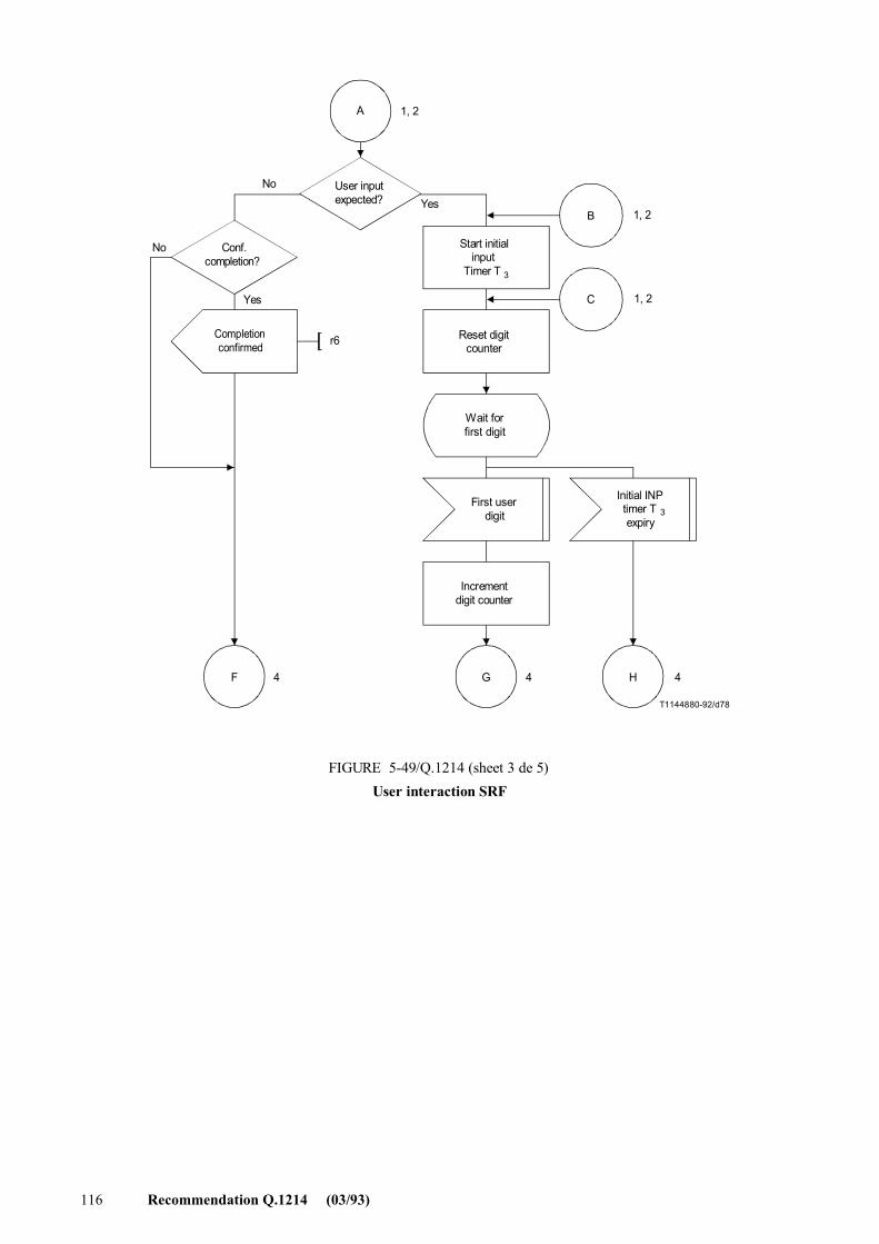
116 Recommendation Q.1214 (03/93)
T1144880-92/d78
A
B
C
F G H
1, 2
1, 2
1, 2
r6
4 4 4
User inputexpected?
Conf.completion?
Completionconfirmed
No
No
Yes
Start initialinput
Timer T 3
Reset digitcounter
Wait forfirst digit
First userdigit
Initial INPtimer Texpiry
3
Incrementdigit counter
FIGURE 5-49/Q.1214 (sheet 3 de 5)User interaction SRF
Yes
FIGURE 5-49/Q.1214...[D78] = 17 CM
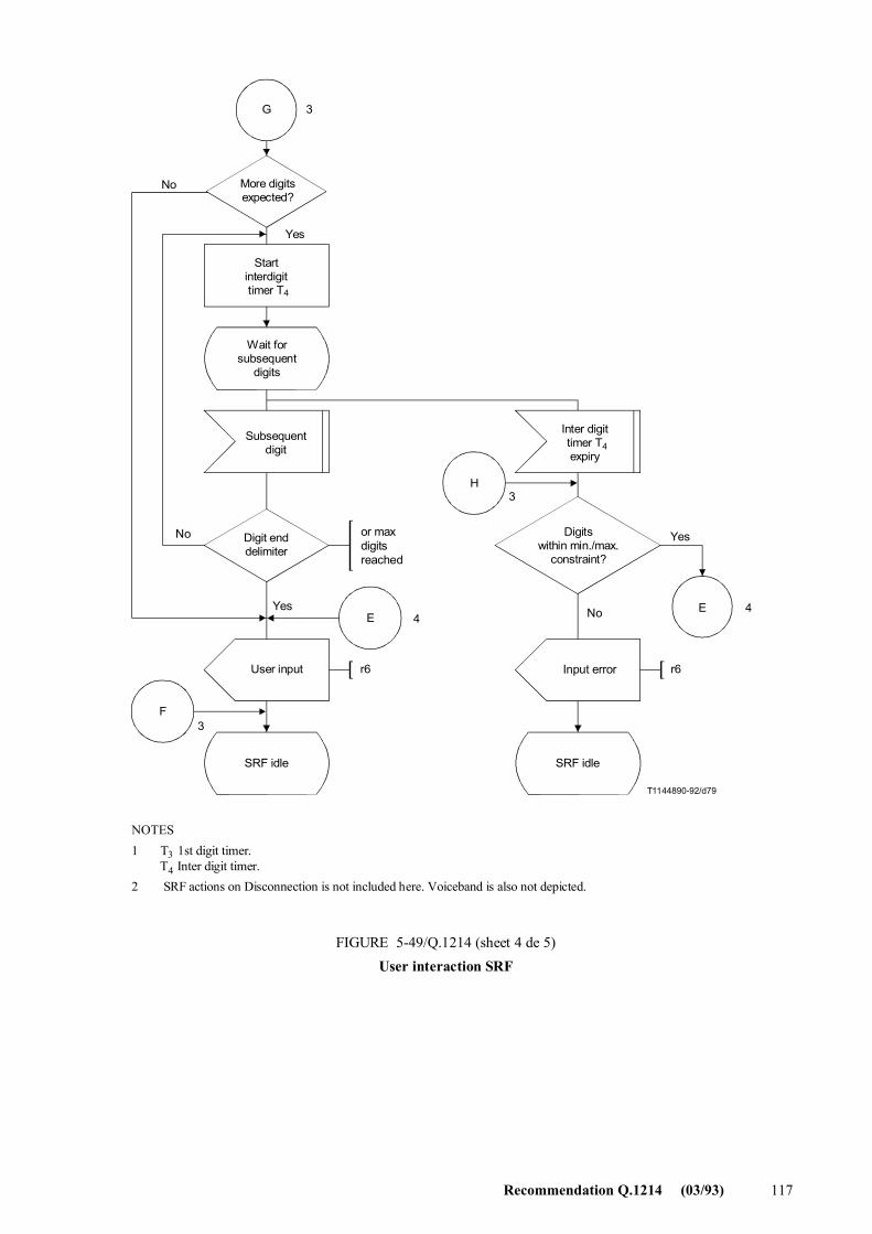
Recommendation Q.1214 (03/93) 117
G
E
F
H
E
T1144890-92/d79
3
3
4
3
4
r6 r6
More digitsexpected?
No
Yes
Startinterdigittimer T4
Wait forsubsequent
digits
Subsequentdigit
Inter digittimer Texpiry
4
Digit enddelimiter
User input
SRF idle
Digitswithin min./max.
constraint?
SRF idle
NOTES1 T 1st digit timer. T Inter digit timer.2 SRF actions on Disconnection is not included here. Voiceband is also not depicted.
3
4
FIGURE 5-49/Q.1214 (sheet 4 de 5)User interaction SRF
No
Yes No
Yesor maxdigitsreached
Input error
FIGURE 5-49/Q.1214...[D79] = 21 CM PLEINE PAGE
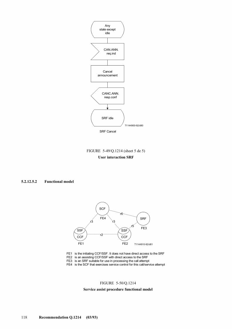
118 Recommendation Q.1214 (03/93)
T1144900-92/d80
Anystate except
idle
CAN.ANN.req.ind
Cancelannouncement
CANC.ANN.resp.conf
SRF idle
SRF Cancel
FIGURE 5-49/Q.1214 (sheet 5 de 5)User interaction SRF
FIGURE 5-49/Q.1214...[D80] = 12 CM
5.2.12.5.2 Functional model
SSF
CCF
SSF
CCF
SCF
SRF
T1144910-92/d81
FE4
FE1 FE2
FE3
r2
r3 r3
r6
r5
FE1 is the initiating CCF/SSF. It does not have direct access to the SRFFE2 is an assisting CCF/SSF with direct access to the SRFFE3 is an SRF suitable for use in processing the call attemptFE4 is the SCF that exercises service control for this call/service attempt
FIGURE 5-50/Q.1214Service assist procedure functional model
FIGURE 5-50/Q.1214...[D81] = 8 CM
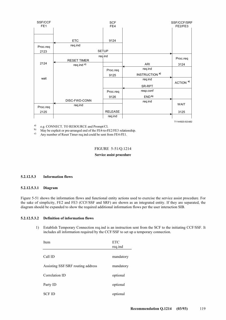
Recommendation Q.1214 (03/93) 119
9124
9125
9126
3124
3125
2123
2124
2125
T1144920-92/d82
SSF/CCFFE1
SCFFE4
SSF/CCF/SRFFE2/FE3
Proc.req
wait
Proc.req
ETCreq.ind
RESET TIMERreq.ind
a)
c)
DISC-FWD-CONNreq.ind
Proc.req
Proc.req
RELEASEreq.ind
ARIreq.ind
INSTRUCTIONreq.ind
SR-RPTresp.conf
ENDreq.ind
Proc.req
ACTION a)
b)
a)b)c)
e.g. CONNECT. TO RESOURCE and Prompt/CI.May be explicit or pre-arranged end of the FE4-to-FE2/FE3 relationship.Any number of Reset Timer req.ind could be sent from FE4-FE1.
FIGURE 5-51/Q.1214Service assist procedure
WAIT
SETUPreq.ind
FIGURE 5-51/Q.1214...[D82] = 12.5 CM
5.2.12.5.3 Information flows
5.2.12.5.3.1 Diagram
Figure 5-51 shows the information flows and functional entity actions used to exercise the service assist procedure. For the sake of simplicity, FE2 and FE3 (CCF/SSF and SRF) are shown as an integrated entity. If they are separated, the diagram should be expanded to show the required additional information flows per the user interaction SIB.
5.2.12.5.3.2 Definition of information flows
1) Establish Temporary Connection req.ind is an instruction sent from the SCF to the initiating CCF/SSF. It includes all information required by the CCF/SSF to set up a temporary connection.
Item ETC req.ind
Call ID mandatory
Assisting SSF/SRF routing address mandatory
Correlation ID optional
Party ID optional
SCF ID optional
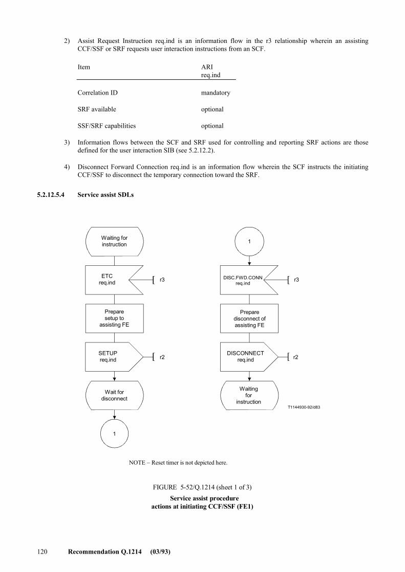
120 Recommendation Q.1214 (03/93)
2) Assist Request Instruction req.ind is an information flow in the r3 relationship wherein an assisting CCF/SSF or SRF requests user interaction instructions from an SCF.
Item ARI req.ind
Correlation ID mandatory
SRF available optional
SSF/SRF capabilities optional
3) Information flows between the SCF and SRF used for controlling and reporting SRF actions are those defined for the user interaction SIB (see 5.2.12.2).
4) Disconnect Forward Connection req.ind is an information flow wherein the SCF instructs the initiating CCF/SSF to disconnect the temporary connection toward the SRF.
5.2.12.5.4 Service assist SDLs
1
1
T1144930-92/d83
r3 r3
r2 r2
Waiting forinstruction
ETCreq.ind
Preparesetup to
assisting FE
SETUPreq.ind
Wait fordisconnect
DISC.FWD.CONNreq.ind
Preparedisconnect ofassisting FE
DISCONNECTreq.ind
Waitingfor
instruction
NOTE � Reset timer is not depicted here.
FIGURE 5-52/Q.1214 (sheet 1 of 3)Service assist procedure
actions at initiating CCF/SSF (FE1)
FIGURE 5-52/Q.1214...[D83] = 15 CM
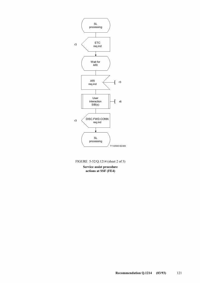
Recommendation Q.1214 (03/93) 121
T1144940-92/d84
r3
r3
r3
r6
SLprocessing
ETCreq.ind
Wait forARI
ARIreq.ind
Userinteraction
SIB(s)
DISC.FWD.CONNreq.ind
SLprocessing
FIGURE 5-52/Q.1214 (sheet 2 of 3)Service assist procedure
actions at SSF (FE4)
FIGURE 5-52/Q.1214...[D84] = 16.5 CM
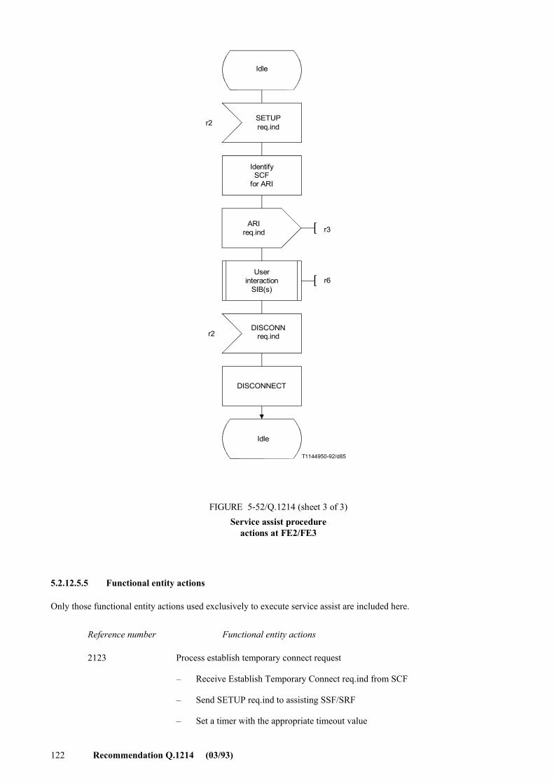
122 Recommendation Q.1214 (03/93)
T1144950-92/d85
r2
r2
r3
r6
Idle
SETUPreq.ind
IdentifySCF
for ARI
ARIreq.ind
Userinteraction
SIB(s)
DISCONNreq.ind
DISCONNECT
Idle
FIGURE 5-52/Q.1214 (sheet 3 of 3)Service assist procedure
actions at FE2/FE3
FIGURE 5-52/Q.1214...[D85] = 18.5 CM
5.2.12.5.5 Functional entity actions
Only those functional entity actions used exclusively to execute service assist are included here.
Reference number Functional entity actions
2123 Process establish temporary connect request
� Receive Establish Temporary Connect req.ind from SCF
� Send SETUP req.ind to assisting SSF/SRF
� Set a timer with the appropriate timeout value
Recommendation Q.1214 (03/93) 123
2124 Reset timer
� Update the value of the timer with the value received from SCF
2125 Process Forward Disconnect
� Receive Forward Disconnect req.ind from SCF
� Send DISCONNECT req.ind to the assisting SSF/SRF
9124 Request Temporary Connection
� Send Establish Temporary Connect req.ind to SSF
� Wait for assisting SSF/SRF
9125 Process assist request instructions
� Receive Assist Request Instruction req.ind from assisting SSF
� Proceed with user interaction information flows
9126 End Assist
� Send Clear Assist req.ind to assisting SSF/SRF
� Send Forward Disconnect req.ind to initiating SSF
� Proceed with instructions to initiating SSF
3124 Detect assist request
� Detect service assist trigger during call processing
� Send Assist Request Instruction req.ind to proper SCF
� Wait for user interaction instructions from SCF
3125 Receive end assist
� Receive Clear Assist req.ind from SCF
� End service assist procedure
� Wait for Disconnect req.ind from initiating SSF
5.2.12.6 Service hand-off capability
5.2.12.6.1 Description
The service hand-off procedure is used where an initiating CCF/SSF does not have direct access to a suitable SRF required for processing a call/service attempt. The service hand-off procedure allows the initiating CCF/SSF to advance the attempt to a CCF/SSF that has direct access to the SRF. At the conclusion of SRF usage, the call attempt is advanced from the latter CCF/SSF.
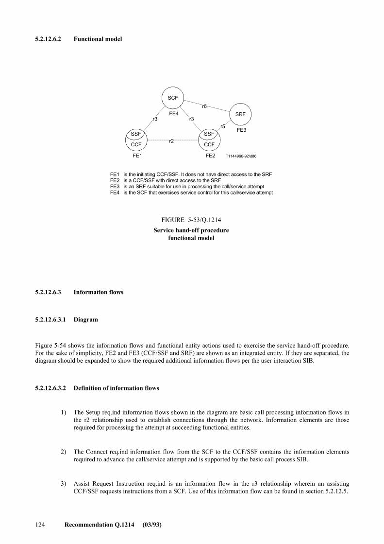
124 Recommendation Q.1214 (03/93)
5.2.12.6.2 Functional model
SSF
CCF
SSF
CCF
SCF
SRF
T1144960-92/d86
FE4
FE1 FE2
FE3
r2
r3 r3
r6
r5
FE1 is the initiating CCF/SSF. It does not have direct access to the SRFFE2 is a CCF/SSF with direct access to the SRFFE3 is an SRF suitable for use in processing the call/service attemptFE4 is the SCF that exercises service control for this call/service attempt
FIGURE 5-53/Q.1214Service hand-off procedure
functional model
FIGURE 5-53/Q.1214...[D86] = 8 CM
5.2.12.6.3 Information flows
5.2.12.6.3.1 Diagram
Figure 5-54 shows the information flows and functional entity actions used to exercise the service hand-off procedure. For the sake of simplicity, FE2 and FE3 (CCF/SSF and SRF) are shown as an integrated entity. If they are separated, the diagram should be expanded to show the required additional information flows per the user interaction SIB.
5.2.12.6.3.2 Definition of information flows
1) The Setup req.ind information flows shown in the diagram are basic call processing information flows in the r2 relationship used to establish connections through the network. Information elements are those required for processing the attempt at succeeding functional entities.
2) The Connect req.ind information flow from the SCF to the CCF/SSF contains the information elements required to advance the call/service attempt and is supported by the basic call process SIB.
3) Assist Request Instruction req.ind is an information flow in the r3 relationship wherein an assisting CCF/SSF requests instructions from a SCF. Use of this information flow can be found in section 5.2.12.5.

Recommendation Q.1214 (03/93) 125
T1144970-92/d87
SSF/CCFFE1
SCFFE4
CCF/SSF/SRFFE2/FE3
CONNECTreq.ind
Proc.req
9125
Proc.Info
ARIreq.ind
INSTRUCTION
req.ind
a)
SR-RPTresp.conf
b)
Proc.req3124
ACTION
a)b)
e.g. CONNECT. TO. RESOURCE and Prompt/CI.Only illustrative. See 5.2.12.2. for details.
FIGURE 5-54/Q.1214Service hand-off procedure
a)
SETUPreq.ind
Proc.req
FIGURE 5-54/Q.1214...[D87] = 11.5 CM
5.2.12.6.4 Service hand-off SDLs
T1144980-92/D88
r3
r2
Waitingfor
instruction
CONNECTreq.ind
SETUPreq.ind
Idle
FIGURE 5-55/Q.1214Service hand-off procedure
actions at initiating CCF/SSF (FE)
FIGURE 5-55/Q.1214...[D88] = 10 CM
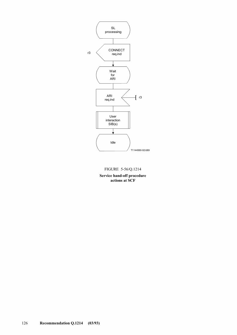
126 Recommendation Q.1214 (03/93)
T1144990-92/d89
r3
r3
SL processing
CONNECTreq.ind
WaitforARI
ARIreq.ind
Userinteraction
SIB(s)
Idle
FIGURE 5-56/Q.1214Service hand-off procedure
actions at SCF
FIGURE 5-56/Q.1214...[D89] = 14 CM
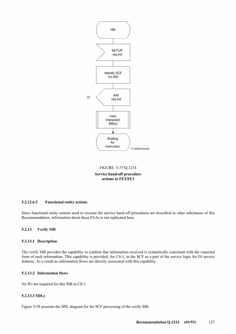
Recommendation Q.1214 (03/93) 127
T1145000-92/d90
r3
Idle
SETUPreq.ind
Identify SCFfor ARI
ARIreq.ind
Userinteraction
SIB(s)
Waitingfor
instruction
FIGURE 5-57/Q.1214Service hand-off procedure
actions at FE2/FE3
FIGURE 5-57/Q.1214...[D90] = 14 CM
5.2.12.6.5 Functional entity actions
Since functional entity actions used to execute the service hand-off procedures are described in other subclauses of this Recommendation, information about these FEAs is not replicated here.
5.2.13 Verify SIB
5.2.13.1 Description
The verify SIB provides the capability to confirm that information received is syntactically consistent with the expected form of such information. This capability is provided, for CS-1, in the SCF as a part of the service logic for IN service features. As a result no information flows are directly associated with this capability.
5.2.13.2 Information flows
No IFs are required for this SIB in CS-1.
5.2.13.3 SDLs
Figure 5-58 presents the SDL diagram for the SCF processing of the verify SIB.
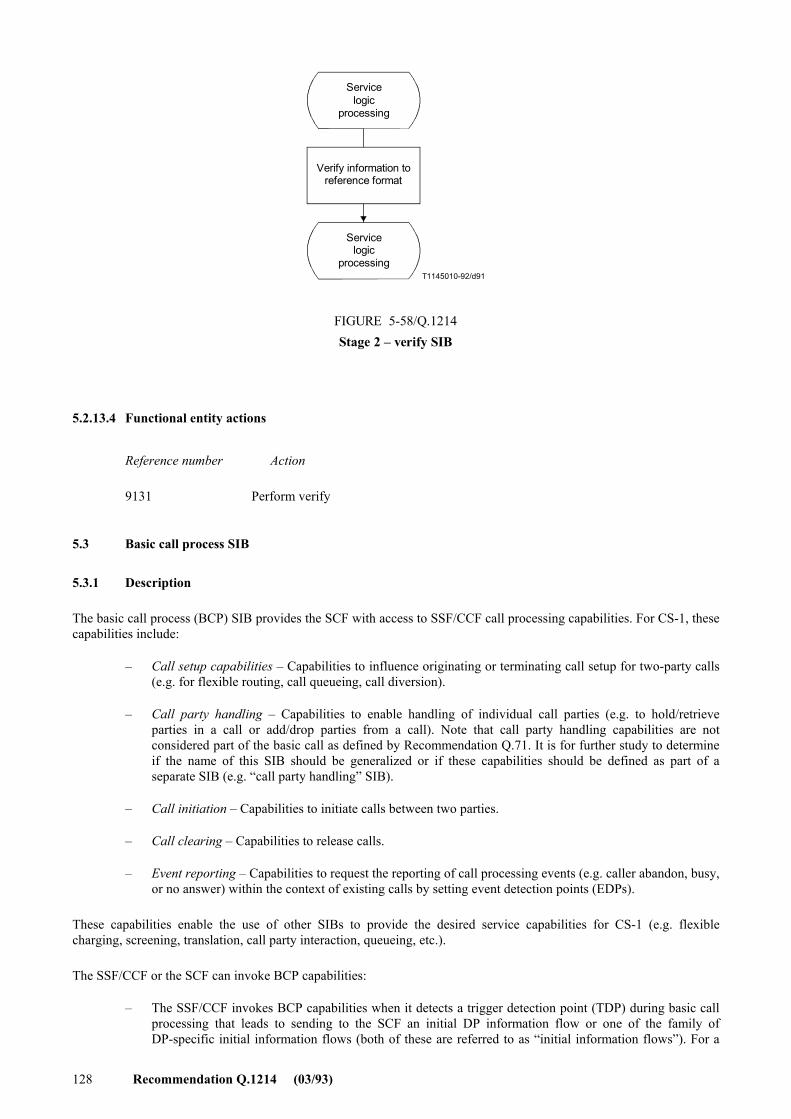
128 Recommendation Q.1214 (03/93)
T1145010-92/d91
Servicelogic
processing
Verify information toreference format
Servicelogic
processing
FIGURE 5-58/Q.1214Stage 2 � verify SIB
FIGURE 5-58/Q.1214...[D91] = 7.5 CM
5.2.13.4 Functional entity actions
Reference number Action
9131 Perform verify
5.3 Basic call process SIB
5.3.1 Description
The basic call process (BCP) SIB provides the SCF with access to SSF/CCF call processing capabilities. For CS-1, these capabilities include:
� Call setup capabilities � Capabilities to influence originating or terminating call setup for two-party calls (e.g. for flexible routing, call queueing, call diversion).
� Call party handling � Capabilities to enable handling of individual call parties (e.g. to hold/retrieve parties in a call or add/drop parties from a call). Note that call party handling capabilities are not considered part of the basic call as defined by Recommendation Q.71. It is for further study to determine if the name of this SIB should be generalized or if these capabilities should be defined as part of a separate SIB (e.g. �call party handling� SIB).
� Call initiation � Capabilities to initiate calls between two parties.
� Call clearing � Capabilities to release calls.
� Event reporting � Capabilities to request the reporting of call processing events (e.g. caller abandon, busy, or no answer) within the context of existing calls by setting event detection points (EDPs).
These capabilities enable the use of other SIBs to provide the desired service capabilities for CS-1 (e.g. flexible charging, screening, translation, call party interaction, queueing, etc.).
The SSF/CCF or the SCF can invoke BCP capabilities:
� The SSF/CCF invokes BCP capabilities when it detects a trigger detection point (TDP) during basic call processing that leads to sending to the SCF an initial DP information flow or one of the family of DP-specific initial information flows (both of these are referred to as �initial information flows�). For a
Recommendation Q.1214 (03/93) 129
TDP-Request, these information flows establish a control relationship between the SSF/CCF and the SCF, enabling the SCF to return instructions to the SSF/CCF. For a TDP-Notification, these information flows do not establish a control relationship.
� The SCF invokes BCP capabilities when it sends an initiate call information flow to the SSF/CCF outside the context of an existing control relationship (i.e. �out-of-the-blue�)7) This information flow may or may not establish a new control relationship between the SSF/CCF and the SCF, as dictated by the SCF.
Once a control relationship is established, the SCF can send call processing instructions to the SSF/CCF in the form of one or more information flows (e.g. connect plus request report BCSM event, as described below). These instructions may directly follow an initial information flow, or may follow a previous call processing instruction. The former is referred to as an �immediate instruction,� and the latter as a �subsequent instruction.�
In the context of a control relationship, the SCF can also request the SSF/CCF to report subsequent call processing events. It does so via the request report BCSM event information flow, which arms event detection points (EDPs) in call processing. When the SSF/CCF detects an armed EDP, it reports it to the SCF in the event report BCSM information flow or one of the family of DP-specific information flows (both of these are referred to as �report information flows�). For an EDP-Request, the SSF/CCF sends the appropriate report information flow, then waits for additional instructions from the SCF; for an EDP-Notification, the SSF/CCF sends the appropriate report information flow, then continues call processing without waiting for additional instructions. Note that the request report BCSM event information flow may be combined with other call processing information flows.
These SSF/CCF-SCF information flow interactions are illustrated in the information flow diagrams in 5.3.2.1, and the individual information flows are briefly described in 5.3.2.2.
The valid call processing information flows that the SCF can send to the SSF/CCF at a given point in time depend on the context of the call at that time (i.e. the state of the call and call party connections). These information flows can be grouped into those that are valid during two-party call setup and clearing, those that are valid during the active state of a call, and those that are valid for multiparty calls. Subclause 5.3.3 provides information flow SDLs for two-party call setup and clearing. Appendix I provides a starting point for the latter SDLs, which remain for further study.
5.3.2 Information flows
5.3.2.1 Diagrams
Figure 5-59 depicts the general information flows and functional entity actions to support BCP capabilities invoked by the SSF/CCF (left-hand column) or by the SCF (right-hand column).
5.3.2.2 Definition of information flows
This subclause briefly defines the BCP information flows. See subclause 6 for detailed information flow and information element descriptions.
1) Initial and report information flows a) Initial DP req.ind � Information flow from the SSF to the SCF to request instructions from the SCF.
The SSF generates it when a trigger is detected at any DP in the BCSM. b) DP-specific Initial information flow family � Family of information flows from the SSF to the SCF
to request instructions from the SCF. This family is an alternative to the Initial DP req.ind. When a
_______________ 7) Initiate_Call may also be used within the context of an existing control relationship, independent of whether the SSF/CCF or SCF
initiated the relationship. This is for further study (see Appendix I).
130 Recommendation Q.1214 (03/93)
trigger is detected at a specific DP in the BCSM, the SSF generates the corresponding DP-specific Initial information flow. The specific BCSM DP is reflected in the corresponding information flow name.
� Origination Attempt Authorized req.ind ;
� Collected Information req.ind;
� Analysed Information req.ind;
� Route Select Failure req.ind;
� OCalledPartyBusy req.ind;
� ONoAnswer req.ind;
� OAnswer req.ind;
� OMidCall req.ind;
� ODisconnect req.ind;
� Term Attempt Authorized req.ind;
� TCalledPartyBusy req.ind;
� TNoAnswer req.ind;
� TAnswer req.ind;
� TMidCall req.ind;
� TDisconnect req.ind;
c) Event Report BCSM req.ind � Information flow from the SSF to the SCF to notify the SCF that an armed EDP was encountered, as previously requested by the SCF in a request report BCSM event information flow. For an EDP-R, this information flow serves to request instructions from the SCF within the context of an existing control relationship.
d) DP-specific report information flow family � Family of information flows from the SSF to the SCF to notify the SCF that an armed EDP was encountered, as previously requested by the SCF in a request report BCSM event information flow. This family is an alternative to the event report BCSM req.ind The DP-specific initial information flow family is used for both initial and report information flows.
2) Call setup and clearing
a) Connect req.ind (Route to a Destination) � Information flow from the SCF to the SSF during the call setup phase to complete a call to a defined destination, or to forward a call to another destination.
b) Proceed with Call Processing family � Family of information flows from the SCF to the SSF to resume call processing at a specific point in call (PIC) of the BCSM. The specific BCSM PIC is reflected in the name of the corresponding information flow. These information flows are valid when the SSF has suspended call processing at specific DPs, as identified for each information flow.
� Collect Information req.ind � This information flow is valid when call processing is suspended at one of the following DPs:
• Origination_Attempt_Authorized
• Collected_Info
• Analysed_Info
• Route_Select_Failure
• O_Called_Party_Busy
• O_No_Answer
• O_Disconnect (called party disconnect only)
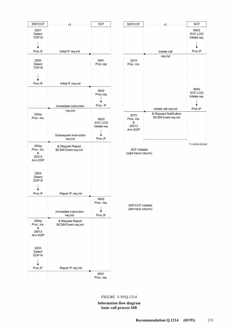
Recommendation Q.1214 (03/93) 131
r3 r3
T1145020-92/d92
SSF/CCF SCF SSF/CCF SCF
2001DetectTDP-N
Proc.IF
2002DetectTDP-R
Proc.IF
9001Proc.req
9002Proc.req
Proc. IF
2015Proc. ins.
Initial IF req.ind Initiate callreq.ind
Proc.IF
Proc.IF
Initiate call req.indImmediate instruction
req.ind200xy
Proc. ins.
Subsequent instructionreq.ind Proc.IF
2015Proc. ins.
&20013
Arm EDP
& Request NotificationBCSM Event req.ind
SCF initiated(right-hand column)
200xyProc. ins.
&20013
Arm EDP
& Request ReportBCSM Event req.ind
Proc.IF
Report IF req.ind
9002Proc. req.
Proc.IF
2004DetectEDP-R
Immediate instructionreq.ind
SSF/CCF initiated(left-hand column)
& Request ReportBCSM Event req.ind
200xyProc. ins.
&20013
Arm EDP
2003DetectEDP-N
Proc.IF Report IF req.ind
9001Proc. req.
FIGURE 5-59/Q.1214Information flow diagram
basic call process SIB
9003SVC LOGInitiate req.
Initial IF req.ind
9003SVC LOGInitiate req.
9003SVC LOGInitiate req.
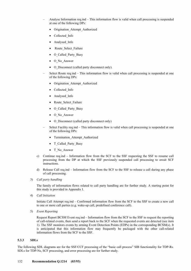
132 Recommendation Q.1214 (03/93)
� Analyse Information req.ind � This information flow is valid when call processing is suspended at one of the following DPs:
• Origination_Attempt_Authorized
• Collected_Info
• Analysed_Info
• Route_Select_Failure
• O_Called_Party_Busy
• O_No_Answer
• O_Disconnect (called party disconnect only).
� Select Route req.ind � This information flow is valid when call processing is suspended at one of the following DPs:
• Origination_Attempt_Authorized
• Collected_Info
• Analysed_Info
• Route_Select_Failure
• O_Called_Party_Busy
• O_No_Answer
• O_Disconnect (called party disconnect only)
� Select Facility req.ind � This information flow is valid when call processing is suspended at one of the following DPs:
• Termination_Attempt_Authorized
• T_Called_Party_Busy
• T_No_Answer
c) Continue req.ind � Information flow from the SCF to the SSF requesting the SSF to resume call processing from the DP at which the SSF previously suspended call processing to await SCF instructions.
d) Release Call req.ind � Information flow from the SCF to the SSF to release a call during any phase of call processing.
3) Call party handling
The family of information flows related to call party handling are for further study. A starting point for this study is provided in Appendix I.
4) Call Initiation
Initiate Call Attempt req.ind � Confirmed information flow from the SCF to the SSF to create a new call to one or more call parties (e.g. wake-up call, predefined conference call).
5) Event Reporting
Request Report BCSM Event req.ind � Information flow from the SCF to the SSF to request the reporting of call-related events, then send a report back to the SCF when the requested events are detected (see item 1). The SSF monitors events by arming Event Detection Points (EDPs) in the corresponding BCSM(s). It is anticipated that this information flow may frequently be packaged with the other call-related information flows from the SCF to the SSF.
5.3.3 SDLs
The following SDL diagrams are for the SSF/CCF processing of the �basic call process� SIB functionality for TDP-Rs. SDLs for TDP-Ns, SCF processing, and error processing are for further study.
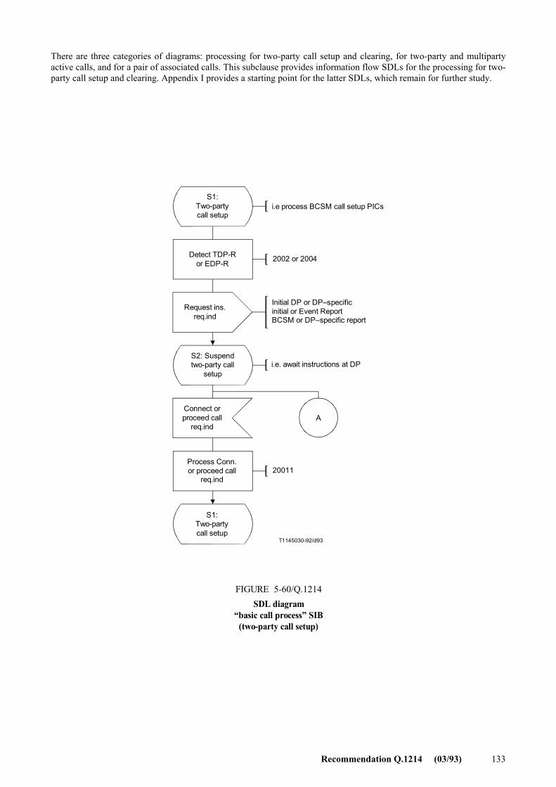
Recommendation Q.1214 (03/93) 133
There are three categories of diagrams: processing for two-party call setup and clearing, for two-party and multiparty active calls, and for a pair of associated calls. This subclause provides information flow SDLs for the processing for two-party call setup and clearing. Appendix I provides a starting point for the latter SDLs, which remain for further study.
T1145030-92/d93
A
S1:Two-partycall setup
i.e process BCSM call setup PICs
Detect TDP-Ror EDP-R 2002 or 2004
Request ins.req.ind
Initial DP or DP�specificinitial or Event ReportBCSM or DP�specific report
S2: Suspendtwo-party call
setupi.e. await instructions at DP
Connect orproceed call
req.ind
Process Conn.or proceed call
req.ind20011
S1:Two-partycall setup
FIGURE 5-60/Q.1214SDL diagram
�basic call process� SIB(two-party call setup)
FIGURE 5-60/Q.1214...[D93] = 17 CM
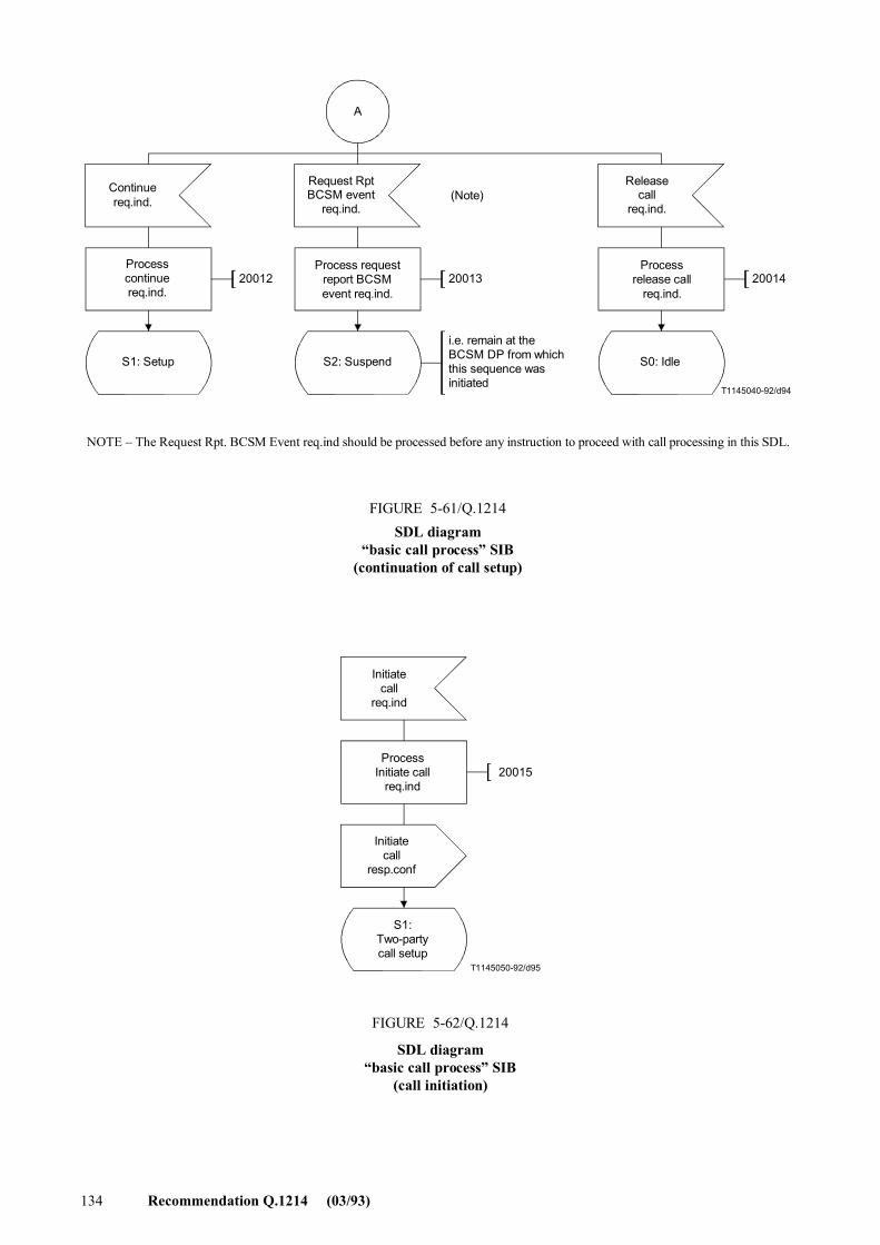
134 Recommendation Q.1214 (03/93)
200142001320012
T1145040-92/d94
A
Continuereq.ind.
Request RptBCSM event
req.ind.
Releasecall
req.ind.
Processcontinuereq.ind.
Process requestreport BCSMevent req.ind.
Processrelease call
req.ind.
S1: Setup S2: Suspend S0: Idle
(Note)
i.e. remain at theBCSM DP from whichthis sequence wasinitiated
NOTE � The Request Rpt. BCSM Event req.ind should be processed before any instruction to proceed with call processing in this SDL.
FIGURE 5-61/Q.1214SDL diagram
�basic call process� SIB(continuation of call setup)
FIGURE 5-61/Q.1214...[D94] = 12 CM
T1145050-92/d95
20015
Initiatecall
req.ind
ProcessInitiate call
req.ind
Initiatecall
resp.conf
S1:Two-partycall setup
FIGURE 5-62/Q.1214
SDL diagram�basic call process� SIB
(call initiation)
FIGURE 5-62/Q.1214...[D95] = 10.5 CM
Recommendation Q.1214 (03/93) 135
5.3.4 Functional entity actions
Functional entities are assumed to have the basic capabilities required to properly perform their assigned function in the IN. Only functional entity actions (FEAs) pertinent to the �basic call process� SIB are shown in the information flow diagram and SDLs. Reference numbers have been arbitrarily assigned to cross-reference the FEAs shown in 5.3.2.1 and 5.3.3 with these descriptions:
Reference number Action
9001 Process request
� process initial information flow (e.g. Initial DP or DP-specific)
9002 Process request and send immediate instruction
� process initial or report information flow (e.g. Initial DP, DP-specific, or event report BCSM) and send one or more BCP information flows in response
9003 Initiate request
� send one or more BCP information flows
2001 Detect trigger detection point � notification
� send initial DP or DP-specific Initial req.ind
2002 Detect trigger detection point � request
� send initial DP or DP-specific initial req.ind and suspend call processing
2003 Detect event detection point � notification
� send event report BCSM or DP-specific report req.ind
2004 Detect event detection point � request
� send Event Report BCSM or DP-specific report req.ind and suspend call processing
200xy Process one or more BCP information flows from SCF
20011 Process Connect or Proceed with Call Processing req.ind
20012 Process Continue req.ind
20013 Process Request Report BCSM Event req.ind
� Arm EDP(s)
20014 Process Release Call req.ind
20015 Process Initiate Call Attempt req.ind
5.4 Stage 2 description of other distributed functionality
Due to the mapping of global functionality in the global functional plane, as represented by SIBs, to distributed functionality in the distributed functional plane, as represented by information flows and functional entity actions, there is a need for additional distributed functionality that is not reflected in SIBs (e.g. to protect the network against overload, distributed processing errors, or physical network failures). This functionality exists to manage the information flows between functional entities, which only exist on the distributed functional plane. For CS-1, this functionality consists of activity test and call gap functionality, as described in this subclause.
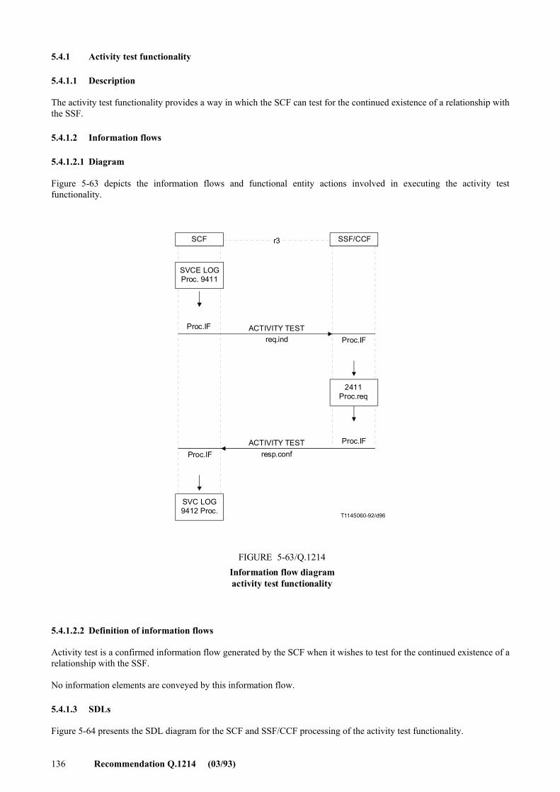
136 Recommendation Q.1214 (03/93)
5.4.1 Activity test functionality
5.4.1.1 Description
The activity test functionality provides a way in which the SCF can test for the continued existence of a relationship with the SSF.
5.4.1.2 Information flows
5.4.1.2.1 Diagram
Figure 5-63 depicts the information flows and functional entity actions involved in executing the activity test functionality.
r3
T1145060-92/d96
SCF SSF/CCF
SVCE LOGProc. 9411
Proc.IF ACTIVITY TESTreq.ind
SVC LOG9412 Proc.
2411Proc.req
ACTIVITY TESTresp.conf
Proc.IF
Proc.IF
Proc.IF
FIGURE 5-63/Q.1214Information flow diagramactivity test functionality
FIGURE 5-63/Q.1214...[D96] = 13.4 CM
5.4.1.2.2 Definition of information flows
Activity test is a confirmed information flow generated by the SCF when it wishes to test for the continued existence of a relationship with the SSF.
No information elements are conveyed by this information flow.
5.4.1.3 SDLs
Figure 5-64 presents the SDL diagram for the SCF and SSF/CCF processing of the activity test functionality.
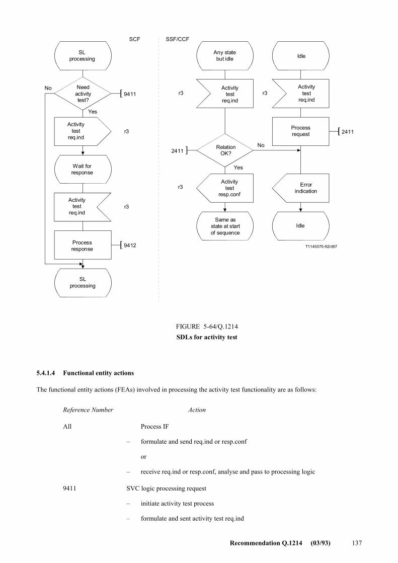
Recommendation Q.1214 (03/93) 137
2411
2411
9411
9412 T1145070-92/d97
SCF SSF/CCF
r3
r3
r3
r3
r3
SLprocessing
No
Yes
No
Yes
Needactivitytest?
Activitytest
req.ind
Wait forresponse
Activitytest
req.ind
Processresponse
Any statebut idle
Activitytest
req.ind
RelationOK?
Activitytest
resp.conf
Same asstate at startof sequence
Idle
Activitytest
req.ind
Processrequest
Errorindication
Idle
SLprocessing
FIGURE 5-64/Q.1214SDLs for activity test
FIGURE 5-64/Q.1214...[D97] = 16 CM
5.4.1.4 Functional entity actions
The functional entity actions (FEAs) involved in processing the activity test functionality are as follows:
Reference Number Action
All Process IF
� formulate and send req.ind or resp.conf
or
� receive req.ind or resp.conf, analyse and pass to processing logic
9411 SVC logic processing request
� initiate activity test process
� formulate and sent activity test req.ind
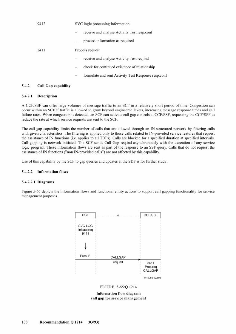
138 Recommendation Q.1214 (03/93)
9412 SVC logic processing information
� receive and analyse Activity Test resp.conf
� process information as required
2411 Process request
� receive and analyse Activity Test req.ind
� check for continued existence of relationship
� formulate and sent Activity Test Response resp.conf
5.4.2 Call Gap capability
5.4.2.1 Description
A CCF/SSF can offer large volumes of message traffic to an SCF in a relatively short period of time. Congestion can occur within an SCF if traffic is allowed to grow beyond engineered levels, increasing message response times and call failure rates. When congestion is detected, an SCF can activate call gap controls at CCF/SSF, requesting the CCF/SSF to reduce the rate at which service requests are sent to the SCF.
The call gap capability limits the number of calls that are allowed through an IN-structured network by filtering calls with given characteristics. The filtering is applied only to those calls related to IN-provided service features that request the assistance of IN functions (i.e. applies to all TDPs). Calls are blocked for a specified duration at specified intervals. Call gapping is network initiated. The SCF sends Call Gap req.ind asynchronously with the execution of any service logic program. These information flows are sent as part of the response to an SSF query. Calls that do not request the assistance of IN functions (�non IN-provided calls�) are not affected by this capability.
Use of this capability by the SCF to gap queries and updates at the SDF is for further study.
5.4.2.2 Information flows
5.4.2.2.1 Diagrams
Figure 5-65 depicts the information flows and functional entity actions to support call gapping functionality for service management purposes.
r3
T1145080-92/d98
SCF CCF/SSF
SVC LOGInitiate req
9411
Proc.IF CALLGAPreq.ind 2411
Proc.reqCALLGAP
FIGURE 5-65/Q.1214Information flow diagram
call gap for service management
FIGURE 5-65/Q.1214...[D98] = 8 CM
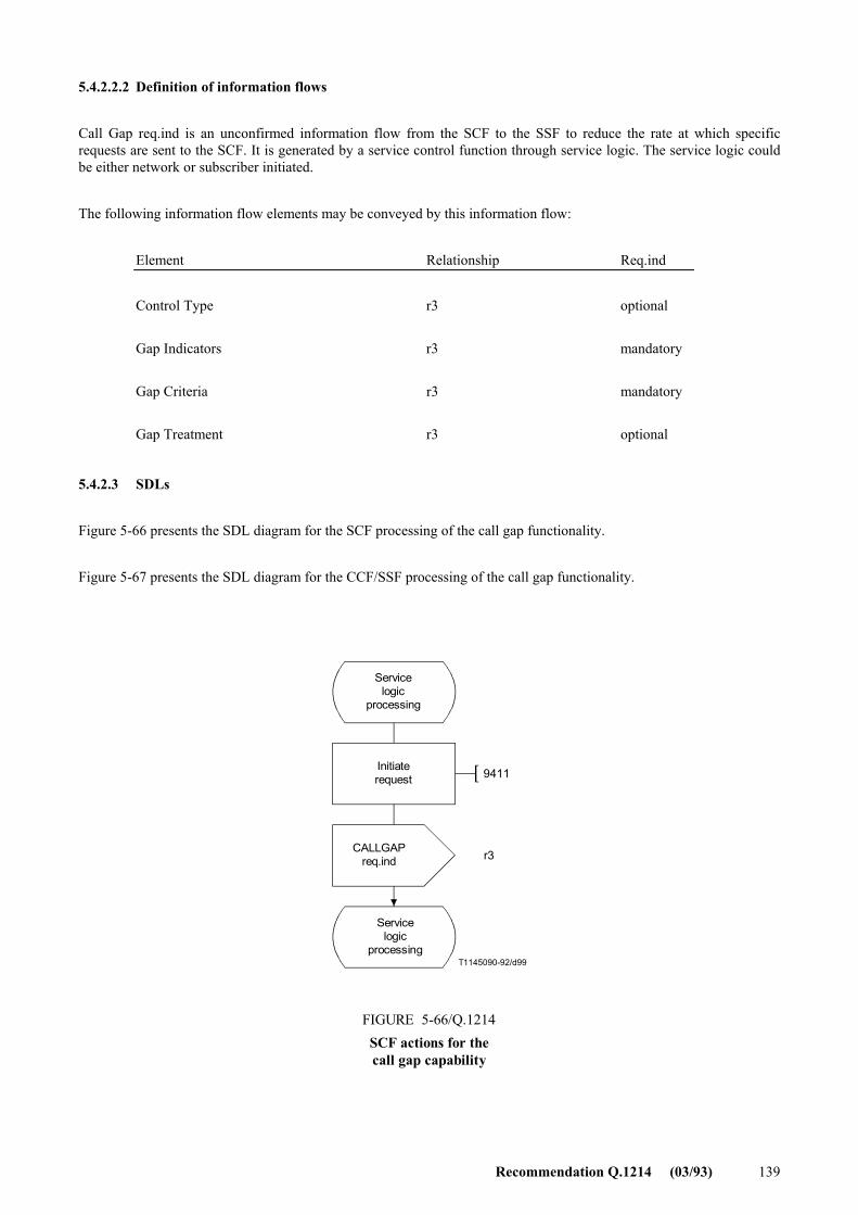
Recommendation Q.1214 (03/93) 139
5.4.2.2.2 Definition of information flows
Call Gap req.ind is an unconfirmed information flow from the SCF to the SSF to reduce the rate at which specific requests are sent to the SCF. It is generated by a service control function through service logic. The service logic could be either network or subscriber initiated.
The following information flow elements may be conveyed by this information flow:
Element Relationship Req.ind
Control Type r3 optional
Gap Indicators r3 mandatory
Gap Criteria r3 mandatory
Gap Treatment r3 optional
5.4.2.3 SDLs
Figure 5-66 presents the SDL diagram for the SCF processing of the call gap functionality.
Figure 5-67 presents the SDL diagram for the CCF/SSF processing of the call gap functionality.
T1145090-92/d99
9411
r3
Servicelogic
processing
Initiaterequest
CALLGAPreq.ind
Servicelogic
processing
FIGURE 5-66/Q.1214SCF actions for thecall gap capability
FIGURE 5-66/Q.1214...[D99] = 10.5 CM
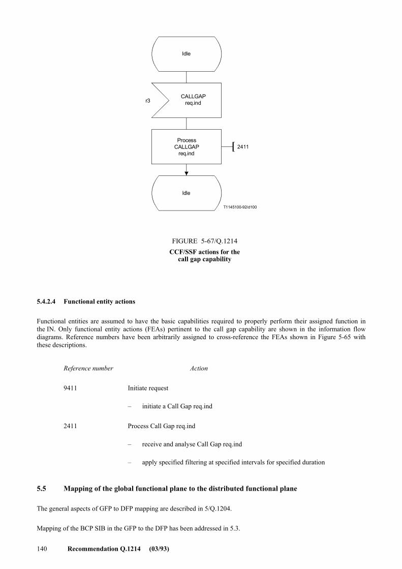
140 Recommendation Q.1214 (03/93)
2411
T1145100-92/d100
r3
Idle
CALLGAPreq.ind
ProcessCALLGAP
req.ind
Idle
FIGURE 5-67/Q.1214CCF/SSF actions for the
call gap capability
FIGURE 5-67/Q.1214...[D100] = 12.5 CM
5.4.2.4 Functional entity actions
Functional entities are assumed to have the basic capabilities required to properly perform their assigned function in the IN. Only functional entity actions (FEAs) pertinent to the call gap capability are shown in the information flow diagrams. Reference numbers have been arbitrarily assigned to cross-reference the FEAs shown in Figure 5-65 with these descriptions.
Reference number Action
9411 Initiate request
� initiate a Call Gap req.ind
2411 Process Call Gap req.ind
� receive and analyse Call Gap req.ind
� apply specified filtering at specified intervals for specified duration
5.5 Mapping of the global functional plane to the distributed functional plane
The general aspects of GFP to DFP mapping are described in 5/Q.1204.
Mapping of the BCP SIB in the GFP to the DFP has been addressed in 5.3.
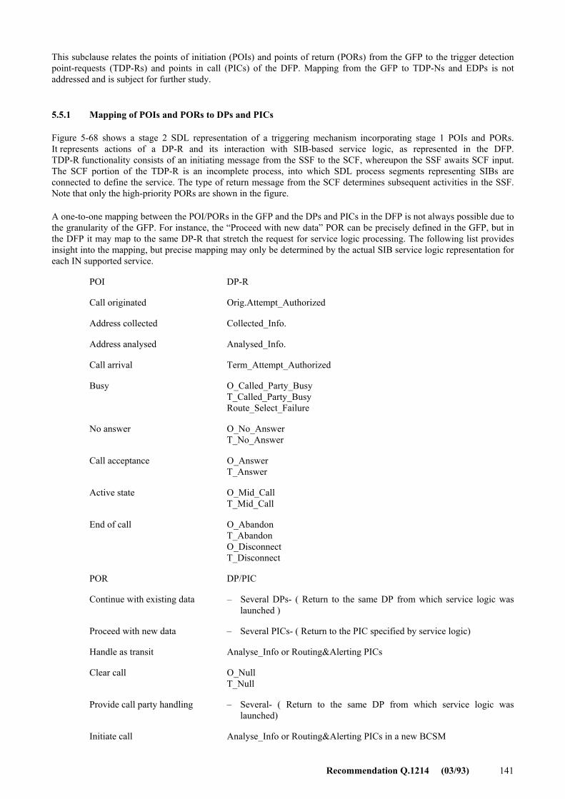
Recommendation Q.1214 (03/93) 141
This subclause relates the points of initiation (POIs) and points of return (PORs) from the GFP to the trigger detection point-requests (TDP-Rs) and points in call (PICs) of the DFP. Mapping from the GFP to TDP-Ns and EDPs is not addressed and is subject for further study. Recommendation Q.1214 (03/93)
5.5.1 Mapping of POIs and PORs to DPs and PICs
Figure 5-68 shows a stage 2 SDL representation of a triggering mechanism incorporating stage 1 POIs and PORs. It represents actions of a DP-R and its interaction with SIB-based service logic, as represented in the DFP. TDP-R functionality consists of an initiating message from the SSF to the SCF, whereupon the SSF awaits SCF input. The SCF portion of the TDP-R is an incomplete process, into which SDL process segments representing SIBs are connected to define the service. The type of return message from the SCF determines subsequent activities in the SSF. Note that only the high-priority PORs are shown in the figure.
A one-to-one mapping between the POI/PORs in the GFP and the DPs and PICs in the DFP is not always possible due to the granularity of the GFP. For instance, the �Proceed with new data� POR can be precisely defined in the GFP, but in the DFP it may map to the same DP-R that stretch the request for service logic processing. The following list provides insight into the mapping, but precise mapping may only be determined by the actual SIB service logic representation for each IN supported service.
POI DP-R
Call originated Orig.Attempt_Authorized
Address collected Collected_Info.
Address analysed Analysed_Info.
Call arrival Term_Attempt_Authorized
Busy O_Called_Party_Busy T_Called_Party_Busy Route_Select_Failure
No answer O_No_Answer T_No_Answer
Call acceptance O_Answer T_Answer
Active state O_Mid_Call T_Mid_Call
End of call O_Abandon T_Abandon O_Disconnect T_Disconnect
POR DP/PIC
Continue with existing data � Several DPs- ( Return to the same DP from which service logic was launched )
Proceed with new data � Several PICs- ( Return to the PIC specified by service logic)
Handle as transit Analyse_Info or Routing&Alerting PICs
Clear call O_Null T_Null
Provide call party handling � Several- ( Return to the same DP from which service logic was launched)
Initiate call Analyse_Info or Routing&Alerting PICs in a new BCSM
142 Recommendation Q.1214 (03/93)
A
B
Τ11
4511
0−92
/d10
1
TDP
crite
riam
et?
Yes
No
Trig
ger
mes
sage
Wai
t for
retu
rn
Trig
ger
mes
sage
Idle
Idle
Con
tinue
with
exi
stin
gda
ta
Con
tinue
with
exis
ting
data
Proc
eed
with
new
dat
aPr
ocee
dw
ithne
w d
ata
Han
dle
as tr
ansi
t
Subs
titut
ene
w d
ata
Subs
titut
ene
w d
ata
Cle
arca
ll
Cle
arca
ll
Han
dle
as tr
ansi
t
Cle
arca
ll
Han
dle
as tr
ansi
t
SIB
LOG
IC
SS
FS
CF
FIG
UR
E 5
-68/
Q.1
214
Stag
e 2
SDL
repr
esen
tatio
n of
a tr
igge
ring
mec
hani
sm in
corp
orat
ing
POIs
and
PO
Rs
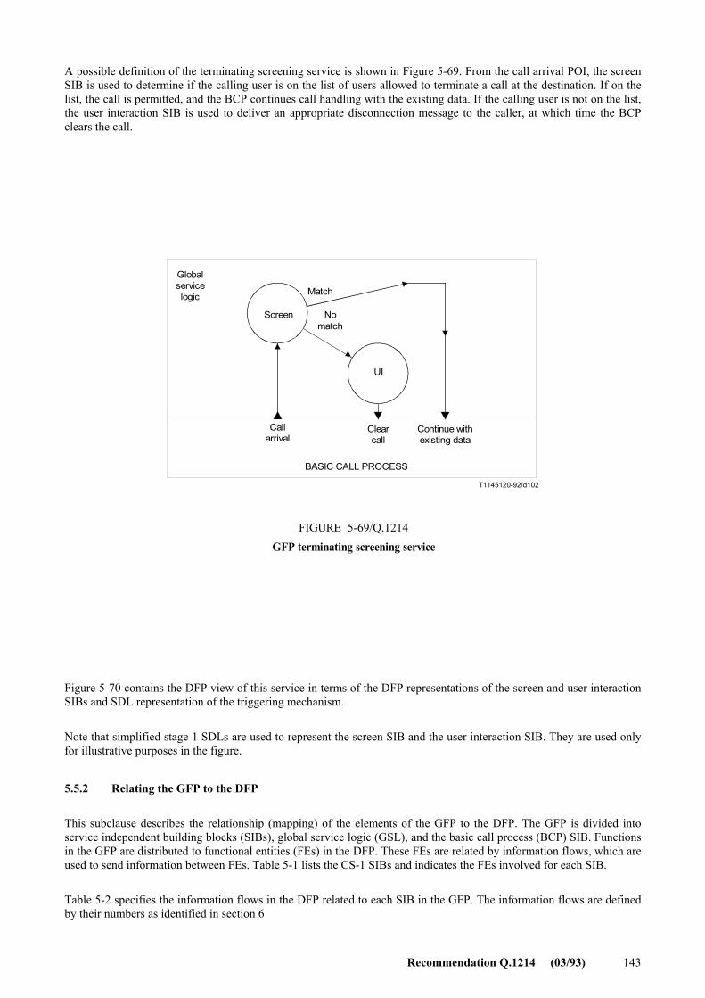
Recommendation Q.1214 (03/93) 143
A possible definition of the terminating screening service is shown in Figure 5-69. From the call arrival POI, the screen SIB is used to determine if the calling user is on the list of users allowed to terminate a call at the destination. If on the list, the call is permitted, and the BCP continues call handling with the existing data. If the calling user is not on the list, the user interaction SIB is used to deliver an appropriate disconnection message to the caller, at which time the BCP clears the call.
T1145120-92/d102
Globalservicelogic Match
Screen Nomatch
Callarrival
Clearcall
Continue withexisting data
BASIC CALL PROCESS
FIGURE 5-69/Q.1214GFP terminating screening service
UI
FIGURE 5-69/Q.1214...[D102] = 8,5 (332%)
Figure 5-70 contains the DFP view of this service in terms of the DFP representations of the screen and user interaction SIBs and SDL representation of the triggering mechanism.
Note that simplified stage 1 SDLs are used to represent the screen SIB and the user interaction SIB. They are used only for illustrative purposes in the figure.
5.5.2 Relating the GFP to the DFP
This subclause describes the relationship (mapping) of the elements of the GFP to the DFP. The GFP is divided into service independent building blocks (SIBs), global service logic (GSL), and the basic call process (BCP) SIB. Functions in the GFP are distributed to functional entities (FEs) in the DFP. These FEs are related by information flows, which are used to send information between FEs. Table 5-1 lists the CS-1 SIBs and indicates the FEs involved for each SIB.
Table 5-2 specifies the information flows in the DFP related to each SIB in the GFP. The information flows are defined by their numbers as identified in section 6
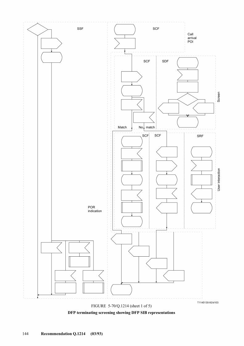
144 Recommendation Q.1214 (03/93)
T1145130-92/d103
SSF SCF
CallarrivalPOI
SCF SDF
Match No match
SCF SCF SRF
Scr
een
Use
r int
erac
tion
PORindication
FIGURE 5-70/Q.1214 (sheet 1 of 5)DFP terminating screening showing DFP SIB representations
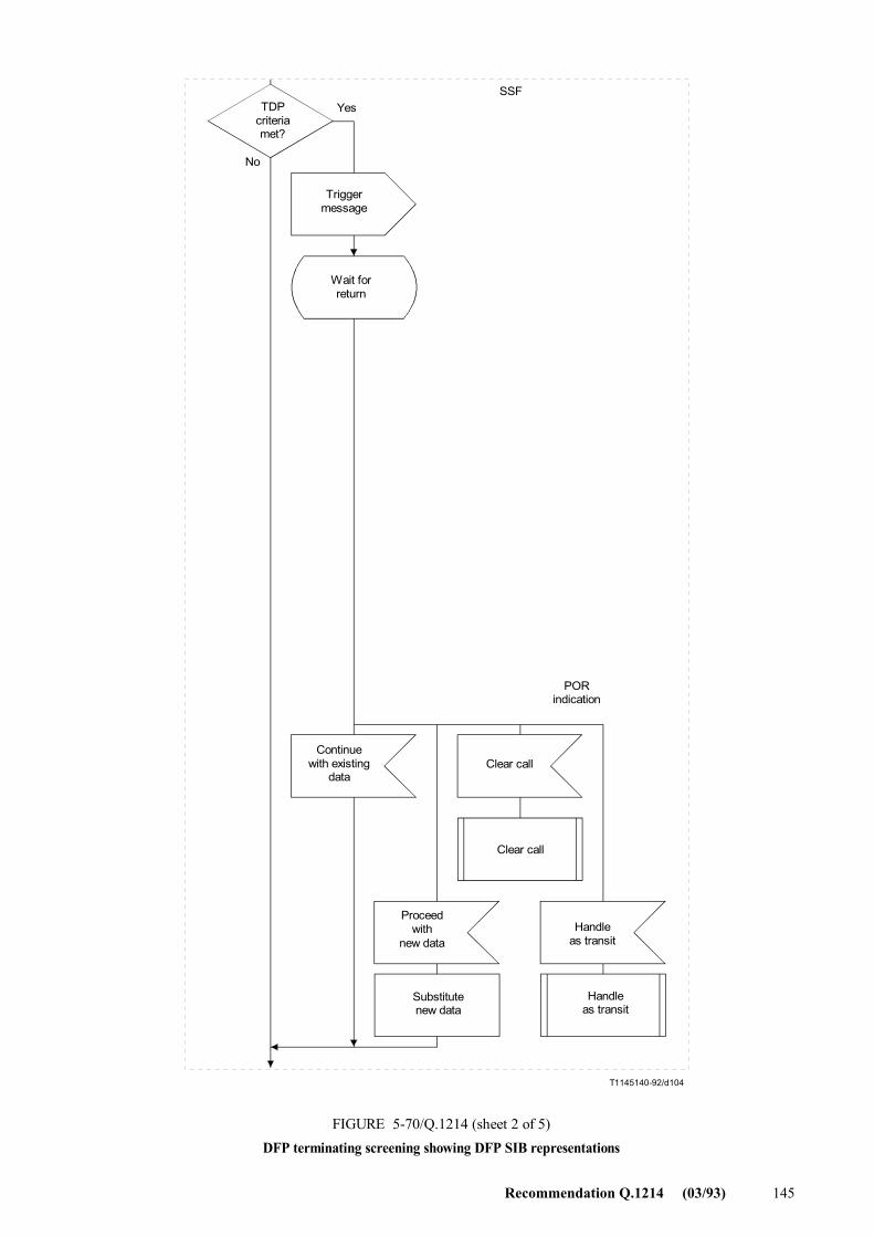
Recommendation Q.1214 (03/93) 145
T1145140-92/d104
TDPcriteriamet?
Triggermessage
Wait forreturn
Yes
No
SSF
Continuewith existing
dataClear call
Clear call
Proceedwith
new dataHandle
as transit
Substitutenew data
Handleas transit
FIGURE 5-70/Q.1214 (sheet 2 of 5)DFP terminating screening showing DFP SIB representations
PORindication
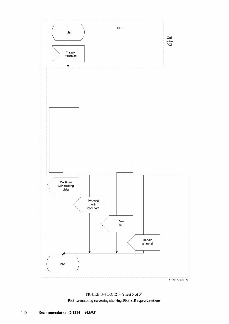
146 Recommendation Q.1214 (03/93)
T1145150-92/d105
Idle
Triggermessage
SCF
Continuewith existing
data
Proceedwith
new data
Clearcall
Handleas transit
Idle
FIGURE 5-70/Q.1214 (sheet 3 of 5)DFP terminating screening showing DFP SIB representations
CallarrivalPOI
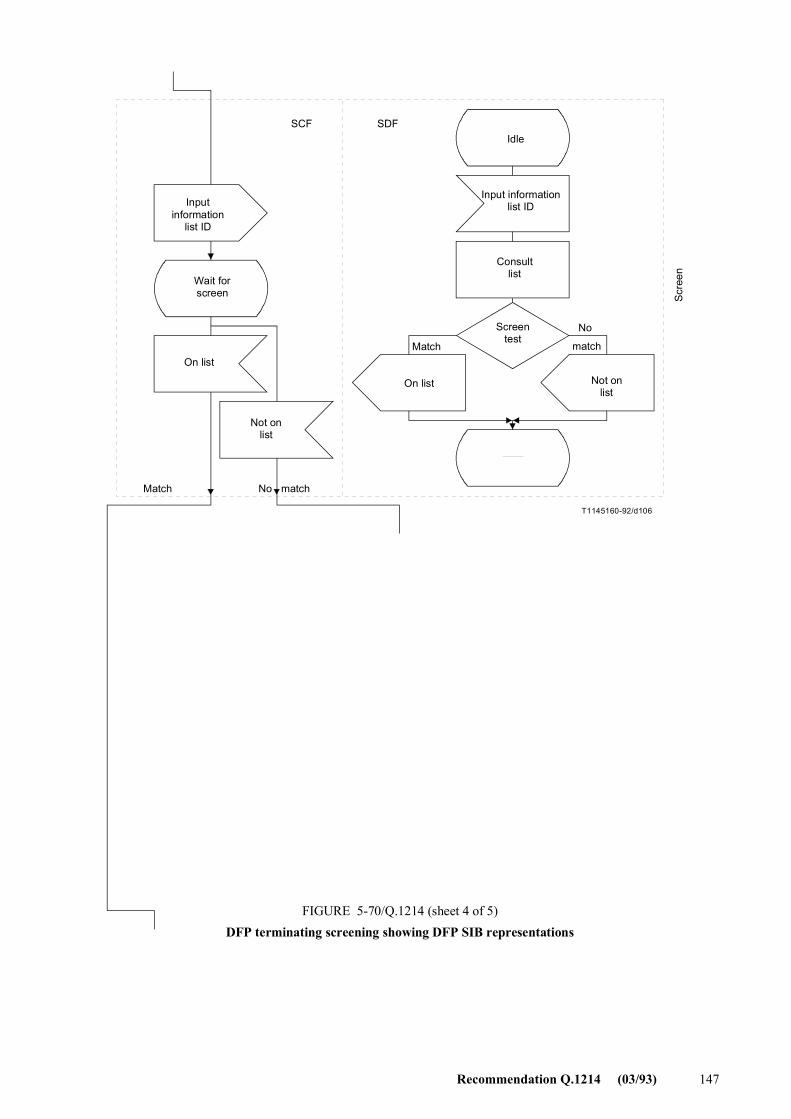
Recommendation Q.1214 (03/93) 147
T1145160-92/d106
SCF SDFIdle
Inputinformation
list ID
Input informationlist ID
Wait forscreen
Consultlist
On list
Screentest
Not onlist
On list Not onlist
Match match
No
Match No match
Scr
een
FIGURE 5-70/Q.1214 (sheet 4 of 5)DFP terminating screening showing DFP SIB representations
FIGURE 5-70/Q.1214.(4/5).[D106] = 23 CM (899%)
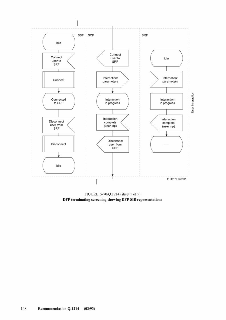
148 Recommendation Q.1214 (03/93)
T1145170-92/d107
Idle
Connectuser toSRF
Connect
Connectedto SRF
Disconnectuser from
SRF
Disconnect
Idle
Connectuser toSRF
Disconnectuser from
SRF
Interaction/parameters
Interactionin progress
Interactioncomplete(user inp)
Interactioncomplete(user inp)
Idle
Interaction/parameters
FIGURE 5-70/Q.1214 (sheet 5 of 5)DFP terminating screening showing DFP SIB representations
SSF SCF SRF
Use
r int
erac
tion
Interactionin progress
FIGURE 5-70/Q.1214.(5/5).[D107] = 17.5 CM (684%)
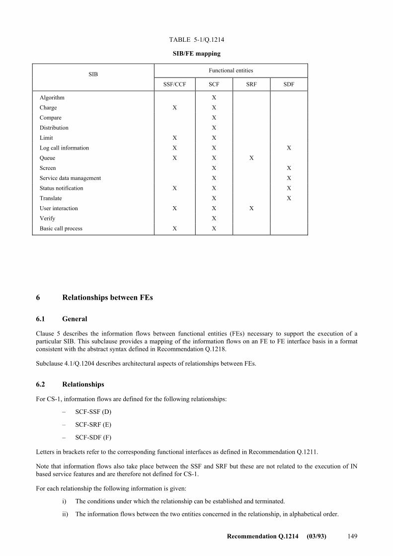
Recommendation Q.1214 (03/93) 149
TABLE 5-1/Q.1214
SIB/FE mapping
6 Relationships between FEs
6.1 General
Clause 5 describes the information flows between functional entities (FEs) necessary to support the execution of a particular SIB. This subclause provides a mapping of the information flows on an FE to FE interface basis in a format consistent with the abstract syntax defined in Recommendation Q.1218.
Subclause 4.1/Q.1204 describes architectural aspects of relationships between FEs.
6.2 Relationships
For CS-1, information flows are defined for the following relationships:
� SCF-SSF (D)
� SCF-SRF (E)
� SCF-SDF (F)
Letters in brackets refer to the corresponding functional interfaces as defined in Recommendation Q.1211.
Note that information flows also take place between the SSF and SRF but these are not related to the execution of IN based service features and are therefore not defined for CS-1.
For each relationship the following information is given:
i) The conditions under which the relationship can be established and terminated.
ii) The information flows between the two entities concerned in the relationship, in alphabetical order.
SIB Functional entities
SSF/CCF SCF SRF SDF
Algorithm X
Charge X X
Compare X
Distribution X
Limit X X
Log call information X X X
Queue X X X
Screen X X
Service data management X X
Status notification X X X
Translate X X
User interaction X X X
Verify X
Basic call process X X
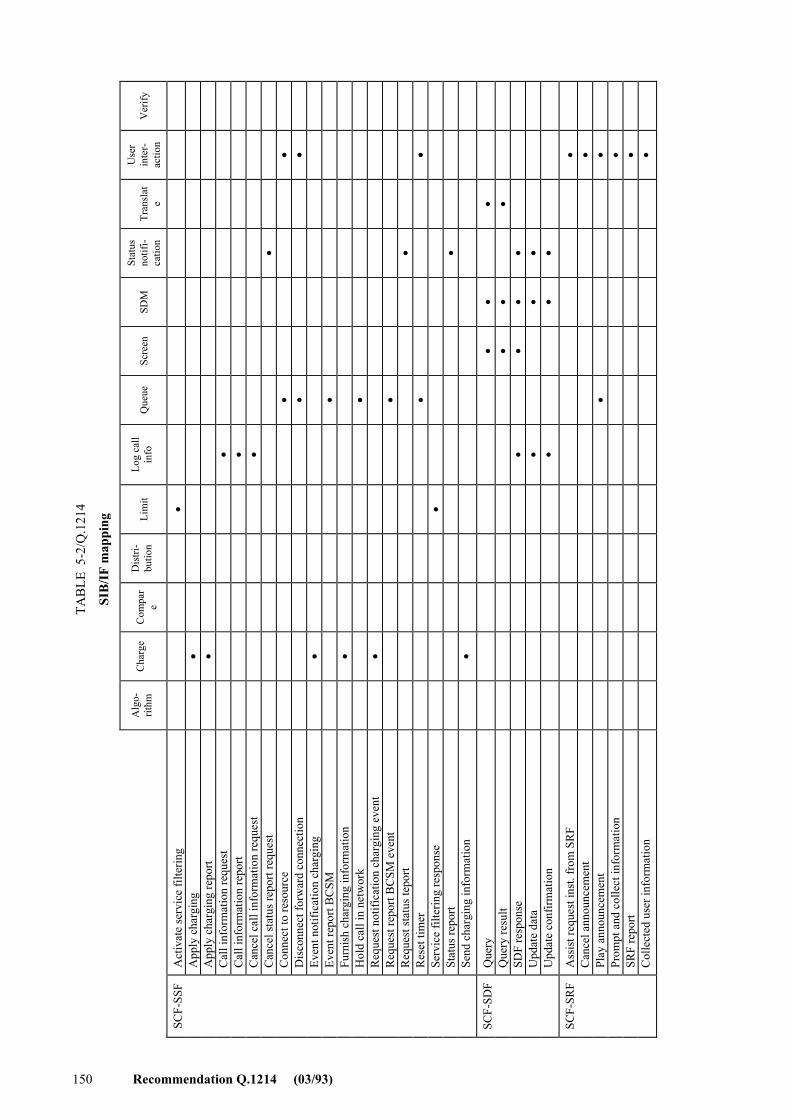
TAB
LE 5
-2/Q
.121
4
SIB
/IF
map
ping
Alg
o-
rithm
C
harg
e
Com
par
e
Dis
tri-
butio
n
Lim
it Lo
g ca
ll in
fo
Q
ueue
Scre
en
SD
M
Stat
us
notif
i-ca
tion
Tr
ansl
ate
Use
r in
ter-
actio
n
V
erify
SCF-
SSF
Act
ivat
e se
rvic
e fil
terin
g
•
A
pply
cha
rgin
g
•
A
pply
cha
rgin
g re
port
•
Cal
l inf
orm
atio
n re
ques
t
•
C
all i
nfor
mat
ion
repo
rt
•
C
ance
l cal
l inf
orm
atio
n re
ques
t
•
C
ance
l sta
tus r
epor
t req
uest
•
C
onne
ct to
reso
urce
•
•
D
isco
nnec
t for
war
d co
nnec
tion
•
•
Even
t not
ifica
tion
char
ging
•
Ev
ent r
epor
t BC
SM
•
Furn
ish
char
ging
info
rmat
ion
•
Hol
d ca
ll in
net
wor
k
•
R
eque
st n
otifi
catio
n ch
argi
ng e
vent
•
R
eque
st re
port
BC
SM e
vent
•
R
eque
st st
atus
tepo
rt
•
R
eset
tim
er
•
•
Serv
ice
filte
ring
resp
onse
•
St
atus
repo
rt
•
Se
nd c
harg
ing
info
rmat
ion
•
SCF-
SDF
Que
ry
•
•
•
Que
ry re
sult
•
•
•
SDF
resp
onse
•
• •
•
U
pdat
e da
ta
•
• •
Upd
ate
conf
irmat
ion
•
• •
SCF-
SRF
Ass
ist r
eque
st in
st. f
rom
SR
F
•
C
ance
l ann
ounc
emen
t
•
Pl
ay a
nnou
ncem
ent
•
•
Prom
pt a
nd c
olle
ct in
form
atio
n
•
SR
F re
port
•
Col
lect
ed u
ser i
nfor
mat
ion
•
150 Recommendation Q.1214 (03/93)
Recommendation Q.1214 (03/93) 151
For each information flow, the following is listed.
a) The name of the information flow.
b) The FE relationship involved (e.g. SSF to SCF, or SCF to SSF).
c) The names of each of the information elements in the information flow. For each IE it is stated whether it is mandatory (M), i.e. it must be included in the IF, or it is optional (O) i.e. there are some circumstances in which the IE may be omitted. If the IE is optional, then the precise circumstances under which it is optional, and any default values are given.
d) The description of each of the IEs. The mapping of IEs to parameters in the signalling protocol is given in 2/Q.1218.
e) Where appropriate, the mapping between this IF and the corresponding FE model(s). This is described in terms of the conditions involved before (pre-condition) and after (post-condition) the IF concerned is either sent or received. For IFs where this is not appropriate reference is made to the corresponding SIB description, in 5. Note that only mappings to two-party call segments are described. Based on appendices, it is FFS whether or not CS-1 will provide capabilities to support multi-party call segments (e.g. for conferencing). However, it is assumed that CS-1 IN capabilities will interwork with non-IN capabilities (e.g. switch-based conferencing features) that may support multi-party call segments [see 4.2.4.2d)] �Applying type A IN technology to type B services�. As such, CS-1 IFs may be applicable to two-party or multi-party call segments, even though the scope of control of the IF is limited to a single party in the call segment.
A summary of all information elements, information flows and associated SIBs is contained in 6.7.
6.3 Information flows between FEs
Information flows between two FEs either consist of a request/response pair or of a request alone. Note that information flows may not map one to one on to signalling messages between the corresponding physical entities in the physical plane.
The SCF performs co-ordination of information flows between FEs when required. Implications on the sequencing of certain information flows are noted.
The complete set of IFs between two FEs defines the relationship between those FEs.
Where necessary, specific information flows have been identified to cancel the effect of other information flows.
Note that both in this subclause and clause 5, IFs relating to error conditions are not described.
6.4 SCF � SSF relationship
6.4.1 General
A relationship between the SCF and SSF is established either as a result of the SSF sending a request for instruction to the SCF, or at the request of the SCF for initiation of a call or for some non call-related reason.
A relationship between an SCF and an SSF is normally terminated at the request of the SCF. The SSF may also terminate the relationship e.g. in error cases.
For CS-1, a single SCF may have concurrent relationships with multiple SSFs. A single SSF may only have a relationship with one SCF at a time for any given call. Note that this refers to control as opposed to monitor relationships.
152 Recommendation Q.1214 (03/93)
When the SSF receives call-related IEs from the SCF, it substitutes these IEs for the corresponding call information, and retains all other call information. This applies to ALL call processing-related messages.
It is FFS to determine whether additional IEs from signalling messages (e.g. IAM ISUP message) should be included in call processing-related messages.
6.4.2 Information flows between SCF and SSF
6.4.2.1 Activate service filtering
a) FE Relationship: SCF to SSF
b) Synopsis
This IF activates service filtering, and may be invoked outside the context of a call. The SCF uses this to instruct the SSF to deal with requests for a specific service and to count each specific attempt. The count of filtered calls will be returned to the SCF after a specified interval.
c) Information elements:
Filtering timeout (M) Filtered call treatment (M) Filtering characteristics (M) Filtering criteria (O) Start time (O)
d) IE descriptions
Filtering timeout defines the maximum duration of the filtering. When the timer expires, a service filtering response is sent to the SCF. It is a choice of either a duration or a specified stop time.
Filtered call treatment specifies how filtered calls are to be treated. It includes information about what announcement should be played, how they are to be billed/charged, how many counters should be used for counting filtered calls and what release cause should be applied to filtered calls.
Filtering characteristics defines the severity of the filtering to be applied and the point in time when the service filtering report will be sent. Filtering characteristics are either interval or number of calls. If interval is set then at periodic intervals, a call will be allowed through and a service filtering response will be sent to the SCF. If number of calls is set, then every Nth call will be allowed through, and a service filtering response will be sent to the SCF.
Filtering criteria is a choice of dialled number, calling line identity or service key. It is used to specify those calls which are to be filtered out. This IE is used when this IF is sent outside the context of a specific call.
Start time defines when the filtering is to start. If it is omitted, the SSF will start filtering immediately.
e) Mapping to FE model(s)
This information flow applies outside the context of an existing relationship between the SCF and the SSF, or within the context of an existing control relationship for a given two-party call segment. In the latter case, it is processed independent of the given call segment.
For further details refer to the stage 2 description of the limit SIB in 5.
Recommendation Q.1214 (03/93) 153
6.4.2.2 Activity test
a) FE Relationship: SCF to SSF
b) Synopsis
This IF is used to check for the continued existence of a relationship between the SCF and SSF. If the relationship is still in existence, then the SSF will respond with activity test response. If no reply is received, then the SCF will assume that the SSF has failed in some way and will take the appropriate action.
c) Information elements
None
d) IE description
Not applicable.
e) Mapping to FE model(s):
For further details refer to the stage 2 description of the activity test functionality in 5.
6.4.2.3 Activity test response
a) FE Relationship: SSF to SCF
b) Synopsis
This IF is the response to the activity test IF.
c) Information elements
None
d) IE description
Not applicable.
e) Mapping to FE model(s):
For further details refer to the stage 2 description of the activity test functionality in 5.
6.4.2.4 Analysed information
a) FE Relationship: SSF to SCF
b) Synopsis
This IF is issued by the SSF after detecting a valid trigger condition at the Analysed Info DP in the BCSM.
c) Information elements
DP specific common elements plus:
Dialled digits (O) Calling party business group ID (O) Calling party sub-address (O) Calling facility group (O) Calling facility group member (O) Prefix (O) Route list (O) Original called party ID (O) Redirecting party ID (O) Redirection information (O) Travelling class mark (O)
154 Recommendation Q.1214 (03/93)
d) IE description
DP specific common elements
These elements are common to all the DP specific requests for instructions. They have the following form:
Call ID (M) Service address information (M) Bearer capability (O) Calling line identity (O) Calling party category (O) SRF/SSF capabilities (O) SRF available (O) Call gapping encountered (O) Terminal type (O) Service profile identifier (O) Location number (O) ISDN access related information (O) Called party number (O)
Call ID identifies a specific instance of a relationship between a SCF and SSF. At the physical plane for CS-1, it is mapped on to a TCAP transaction identity.
Service address information is a sequence of service key and miscellaneous call information. It is used by the SCF to select the correct application. For further details refer to the corresponding IEs in the initial DP IF.
ISDN access related information carries the same information as the protocol element ISUP access transport parameter.
Bearer capability defines the type of bearer required. If the IE is omitted, a default value of �Speech� will be assumed by the SCF.
The remainder of the DP specific common IEs are as defined for the initial DP information flow.
NOTE � Terminal type will default to �Unknown� if the information is not available.
The following IEs are specific to this IF.
Dialled digits are the actual digits received by the SSF from either the calling party (in the case of the originating local exchange) or the previous CCF handling the call (in all other cases).
Calling party business group ID identifies the business group associated with the calling party. The SCF can use this IE to select SLPs based on the group and for authorization purposes. Note that �optional� in this case means that network operators can specify that this IE should be used if their particular network has the information available.
Calling party sub-address is self explanatory.
Calling facility group identifies the facility group for incoming trunks or private facilities. Note that �optional� in this case means that network operators can specify that this IE should be used if their particular network has the information available.
Calling facility group member identifies an individual member of a facility group. Note that �optional� in this case means that network operators can specify that this IE should be used if their particular network has the information available.
Prefix is any prefix digits input by the calling party.
Recommendation Q.1214 (03/93) 155
Route list represents the list of routes which would have been used in order to route the call. It is network operator specific. Note that �optional� in this case means that network operators can specify that this IE should be used if their particular network has the information available. Original called party ID (if available) is the directory number of the first redirecting party (i.e. the number originally dialled by the caller). Redirecting party ID (if available) is the directory number of the last redirecting party. Redirection Information (if available) indicates the reason for forwarding the call from the DN of the first and last redirecting party, and indicates the number of forwardings that have occurred. Travelling class mark, is used to indicate the physical characteristics of the call8).
e) Mapping to FE model(s) The SSF sends this information flow to the SCF upon detecting a DP at DP 3 in an originating BCSM for a two-party call segment. SSF Precondition: 1) Call origination attempt has been initiated; 2) Called party number is available and nature of address is determined; 3) Call gapping or service filtering are not in effect for the call segment; 4) DP criteria have been met; 5) For a TDP-R, there is no existing control relationship influencing the call segment. SSF Postcondition: 1) For a TDP-R, basic call processing has been suspended at DP 3, and a control relationship has been
established; 2) For a TDP-N, basic call processing proceeds at PIC 3, and no control relationship has been
established. SCF Precondition: None. SCF Postcondition: 1) An SLPI has been invoked; 2) For a TDP-R, or EDP-R, an SSF instruction is being prepared.
6.4.2.5 Analyse information a) FE Relationship: SCF to SSF b) Synopsis
This information flow requests the SSF to perform the originating basic call processing actions to analyse destination information that is either collected from a calling party, or provided by the SCF (e.g. for number translation). This includes actions to validate the destination information according to a specified dialling plan, and if valid, to determine call setup information (e.g. called party address, nature of address, and route index to a list of one or more outgoing trunk groups).
_______________ 8) e.g. the usage of echo-cancellors.
156 Recommendation Q.1214 (03/93)
c) Information elements
Call ID (M) Destination routing address (O) ISDN access related information (O) Alerting pattern (O) Original called party ID (O)
A version of this IF incorporating extra IEs may be found in Appendix I.
d) IE description
As previously defined with the following additions.
Destination routing address is a list of called party numbers.
Alerting pattern is the same as the DSS1 signal parameter. It is used to specify the type of alerting to be applied. Since present signalling systems do not convey this information, this IE may only apply at the terminating SSF.
Original called party ID would contain the identity of the first called party. In some services (e.g. call forwarding), it would be necessary for the SCF to specify this number.
e) Mapping to FE model(s)
This information flow only applies during call setup in an originating BCSM for a two-party call segment.
Precondition:
1) Call origination attempt has been initiated;
2) Authority/ability to place outgoing call has been verified;
3) Destination information is available in the SSF or provided by the SCF;
4) Basic call processing has been suspended at DP 1, 2, 3, 4, 5, or 6 (i.e. the call setup phase).
Postcondition:
1) Basic call processing resumes at PIC 3;
2) DP 3, 10, or an exception is encountered.
6.4.2.6 Apply charging
a) FE Relationship: SCF to SSF
b) Synopsis
This IF is to be used for interacting with the SSF on-line mechanisms that are used in calculating the current call charge. This IF may be invoked several times during a call.
c) Information elements
Call ID (M) Billing charging characteristics (M) Party to charge (O) Send calculation to SCF indicator (M)
d) IE description
Billing charging characteristics is network operator specific. It contains any relevant information for calculating the call charge. Examples may be a tariff table that the exchange will apply (taking into account the destination) to calculate the call charge, or a number of pulses to add to the current call charge, or the call tariff itself.
Recommendation Q.1214 (03/93) 157
Party to charge and send calculation to SCF indicator are mutually exclusive. When none of the two IE is present, it is assumed that the A party is to be charged. In this latter case and only in this case, normal advice of charge is provided by the SSF.
Send calculation to SCF indicator is a Boolean, and if TRUE, the call charge is to be calculated by the SSF and sent to the SCF. In this case, the SSF is not recording the charging information at all.
e) Mapping to FE model(s)
This information flow applies in the context of an existing control relationship between the SCF and SSF for a given two-party call segment.
For further details refer to the stage 2 description of the charge SIB in 5.
6.4.2.7 Apply charging report
a) FE Relationship: SSF to SCF
b) Synopsis
This IF is the response to the Apply charging IF, when the report has been previously requested. This result is sent at the end of the call (that is when the switch decides to stop charging).
c) Information elements
Call result (M)
d) IE description
Call Result is network operator specific. It will contain the result of the charging operation (e.g. number of pulses applied).
e) Mapping to FE model(s)
Refer to the stage 2 description of the charge SIB in 5.
6.4.2.8 Assist request instructions
a) FE Relationship: SSF to SCF
b) Synopsis
This IF is sent to the SCF by an SSF, which is acting as the assisting SSF in an assist or hand-off procedure. It is generated when the assisting SSF receives a call from an initiating SSF containing information indicating an assist or hand-off procedure.
NOTE � In the INAP, this information flow and the assist request instructions from SRF information flow are mapped on to a single operation.
c) Information elements
Call ID (M) SSF/SRF capabilities (O) SRF available (O) Correlation ID (M)
d) IE description
SSF/SRF capabilities and SRF available are as defined for initial DP.
Correlation ID is used by the SCF to associate the assist request instructions from the assisting SSF with the initial DP from the initiating SSF. The form of this IE is network Operator optional. It may be extracted from the digits received from the initiating SSF or be all of the digits.
e) Mapping to FE model(s)
An assisting SSF sends this information flow to the SCF as part of an SSF service assist/hand-off.
For further details refer to the stage 2 description of the user interaction SIB in 5.
158 Recommendation Q.1214 (03/93)
6.4.2.9 Call gap
a) FE Relationship SCF to SSF
b) Synopsis
This IF is used to reduce the rate at which specific service requests are sent to the SCF.
c) Information elements
Control Type (O) Gap Indicators (M) Gap Criteria (M) Gap treatment (O)
d) IE description
Control type specifies the reason why gapping is invoked. Examples of values: SCF overload (the SCF has started gapping), Manually initiated (through the SMS). This IE allows the SSF to set priorities among gapped traffic, the manually initiated case having greater priority.
Gap indicators specifies how the gapping is to be applied. The sub-elements are:
Duration (M) Gap Interval (M)
Duration specifies the time for which gapping is to remain in force before being removed by the SSF.
Gap Interval specifies the time allowed between calls being allowed through. An interval of 0 specifies that gapping is to be removed. An interval of �1, specifies that all calls meeting the gap criteria are to be rejected, but only for the time for which call gapping is in force.
Gap criteria specifies which calls are to be gapped. This is a choice of:
� Called party number � Calling party number � Service specific
One and only one of these options must be present:
Called party number means that calls to a specific called party number will be subject to gapping.
Calling party number means that calls from a specific calling party will be subject to gapping.
Service specific means that calls resulting in a request for a specific service key and at a specific DP will be subject to gapping.
Gap treatment specifies how gapped calls are to be treated. It consists of two sub-elements, announcement ID and release cause. If omitted, a default, network operator specific treatment will be assumed.
e) Mapping to FE model(s)
This information flow applies outside the context of an existing relationship between the SCF and the SSF, or within the context of an existing control relationship for a given two-party call segment. In the latter case, it is processed independent of the given call segment.
For further details refer to the stage 2 description of the call gap capability in 5.
Recommendation Q.1214 (03/93) 159
6.4.2.10 Call information report
a) FE Relationship: SSF to SCF
b) Synopsis
This IF is used to send specific call information for a single call to the SCF as requested by the SCF in a previous call information request IF. This IF is sent at the end of the call.
c) Information elements
Requested information (M) Correlation ID (O)
d) IE description
As for call information request.
e) Mapping to FE model(s)
This information flow applies in the context of an existing control relationship for a two-party call segment. The SSF sends this information flow to the SCF at the end of the call.
SSF Precondition:
1) Call origination attempt has been initiated;
2) Requested call information has been collected;
SSF Postcondition:
None.
SCF Precondition:
1) A call information request IF has been sent at the request of an SLPI and the SLPI is expecting a call information report from the SSF.
SCF Postcondition:
None.
For further details refer to the stage 2 description of the log call information SIB in 5.
6.4.2.11 Call information request
a) FE Relationship: SCF to SSF
b) Synopsis
This IF is used to request the SSF to save specific information about a single call and report it to the SCF at the end of the call (see call information report IF ).
c) Information elements
Requested information (M) Correlation ID (O)
d) IE description
Requested information is a list of specific items of information which can be requested. The list is:
Call attempt elapsed time
Call stop time
Call connected elapsed time
Called address
Calling address
Bearer capability
Any set of these items can be requested.
Correlation ID is network operator optional, and is used to correlate the call information report with a previously issued call information request.
160 Recommendation Q.1214 (03/93)
e) Mapping to FE model(s)
This information flow applies in the context of an existing control relationship between the SCF and SSF for a given two-party call segment.
SCF Precondition:
1) A control relationship exists between the SCF and the SSF;
2) The SLPI has determined that a call information request IF should be sent.
SCF Postcondition:
1) The SLPI is expecting a call information report from the SSF;
SSF Precondition:
1) Call origination attempt has been initiated.
SSF Postcondition:
1) Requested call information is retained by the SSF, as specified;
2) If basic call processing is suspended at a DP, the SSF is waiting for further instructions from the SCF.
For further details refer to the stage 2 description of the log call information SIB in 5.
6.4.2.12 Cancel call information request
a) FE Relationship: SCF to SSF
b) Synopsis
This IF is used to cancel a previous call information request. Note that in the INAP this IF is mapped on to a generic cancel operation.
c) Information elements
Operation identifier (M)
d) IE description
Operation identifier identifies the specific call information request to be cancelled. This will be mapped on to an invoke ID in the physical plane.
e) Mapping to FE model(s):
This information flow applies in the context of an existing control relationship for a two-party call segment.
For further details refer to the stage 2 description of the log call information SIB in 5.
6.4.2.13 Cancel status report request
a) FE Relationship: SCF to SSF
b) Synopsis
This IF is used to request the SSF to cancel a previous request to monitor the busy/idle status of a physical termination resource (see request status report IF ).
c) Information elements
Resource ID (M)
d) IE description
Resource ID is used by the SSF to cancel the request status report previously requested against this resource.
e) Mapping to FE model(s)
This information flow applies outside the context of an existing relationship between the SCF and the SSF, or within the context of an existing control relationship for a given two-party call segment. In the latter case, it is processed independent of the given call segment.
For further details refer to the stage 2 description of the status notification SIB in 5.
Recommendation Q.1214 (03/93) 161
6.4.2.14 Collected information
a) FE Relationship: SSF to SCF
b) Synopsis
This IF is issued by the SSF after detecting a valid trigger condition at the collected information DP in the BCSM.
c) Information elements:
DP specific common elements plus:
Calling party business group ID (O) Calling party sub-address (O) Calling facility group (O) Calling facility group member (O) Prefix (O) Original called party ID (O) Redirecting party ID (O) Redirection information (O) Travelling class mark (O) Dialled digits (O)
d) IE description
As previously defined with the following additions.
Calling facility group identifies the facility group for trunks or private facilities from which the call has originated. Note that �optional� in this case means that network operators can specify that this IE should be used if their particular network has the information available.
Calling facility group member identifies an individual member of a calling facility group. Note that �optional� in this case means that network operators can specify that this IE should be used if their particular network has the information available.
e) Mapping to FE model(s)
The SSF sends this information flow to the SCF upon detecting a DP at DP 2 in an originating BCSM for a two-party call segment.
SSF Precondition:
1) Call origination attempt has been initiated;
2) Authority/ability to place outgoing call has been verified;
3) Complete initial information package/dialing string is available from the originating party;
4) Call gapping or service filtering are not in effect for the call segment;
5) DP criteria are met;
6) For a TDP-R, there is no existing control relationship influencing the call segment.
SSF Postcondition:
1) For a TDP-R, basic call processing has been suspended at DP 2 and a control relationship has been established;
2) For a TDP-N, basic call processing proceeds at PIC 3 and no control relationship has been established.
SCF Precondition:
None.
SCF Postcondition:
1) An SLPI has been invoked;
2) For a TDP-R, or EDP-R, an SSF instruction is being prepared.
162 Recommendation Q.1214 (03/93)
6.4.2.15 Collect information
a) FE Relationship: SCF to SSF
b) Synopsis
This information flow requests the SSF to perform the originating basic call processing actions to prompt a calling party for destination information, then collect destination information from the calling party according to a specified numbering plan Indicator (e.g. for virtual private networks).
c) Information elements
Call ID (M) Numbering plan (O) Alerting pattern (O) Travelling class mark (O) Original called party ID (O)
d) IE description
As previously defined with the following additions.
Numbering plan is used to indicate the numbering plan to be used when decoding destination information. If omitted a default value of E.164 numbering will be assumed.
e) Mapping to FE model(s)
This information flow only applies during call setup in an originating BCSM for a two-party call segment, in an SSF which can directly communicate with the calling party.
Precondition:
1) Call origination attempt has been initiated;
2) Authority/ability to place outgoing call has been verified;
3) Basic call processing has been suspended at DP 1, 2, 3, 4, 5, or 6 (i.e. the call setup phase).
Postcondition:
1) Basic call processing resumes at PIC 2;
2) DP 2, 10, or an exception is encountered.
6.4.2.16 Connect
a) FE Relationship: SCF to SSF
b) Synopsis
This IF is used to create a call to a defined destination, in the case of an existing call in the set up phase, or to forward a call to another destination.
c) Information elements
Call ID (M) Destination routing address (M) Alerting pattern (O) ISDN access related information (O) Forwarding condition (O) Route list (O) Travelling class mark (O) Correlation ID (O) SCF ID (O) Cut and paste (O) Original called party ID (O)
A version of this IF incorporating extra IEs may be found in Appendix I.
Recommendation Q.1214 (03/93) 163
d) IE description
As previously defined, with the following additions.
Destination routing address is a list of possible routing addresses. If connect is being used in the context of a hand-off procedure, this IE may contain embedded within it, a correlation ID and SCF ID, but ONLY if correlation ID and SCF ID are not specified separately. In this case, the list only has one address.
Forwarding condition specifies a condition upon which an alternate destination routing address would apply. It has values of �busy�, �no answer�, and �any�.
Route list specifies a list of routes to be used by the SSF.
Correlation ID is used ONLY if connect is being used in the context of a hand-off procedure, AND the correlation ID is not embedded in the destination routing address. The correlation ID will be passed to the SCF by the SSF which the call is handed off to.
SCF ID is used ONLY if connect is being used in the context of a hand-off procedure, AND the SCF ID is not embedded in the destination routing address. It enables the SSF to which the call is handed off to identify which SCF the assist request instructions should be sent to.
Cut and paste is used by the SCF to instruct the SSF to delete(cut) a specified number of the digits it has received from the calling party and paste the remaining dialled digits on to the end of the digits supplied by the SCF in the destination routing address. As an example if the user dials XXX � YYYY, the SSF will trigger on XXX and query the SCF. Note that the SSF will treat the YYYY digits as normal. The SCF will send back new ZZZZ digits and a cut and paste of 3. The SSF will replace XXX with ZZZZ and paste it to YYYY.
e) Mapping to FE model(s)
This information flow only applies before the active PIC in an originating or terminating BCSM for a two-party call segment.
SCF Precondition:
1) A control relationship exists between the SCF and the SSF;
2) An SLPI has determined that a Connect IF should be sent by the SCF.
SCF Postcondition:
1) SLPI execution may continue.
SSF Precondition:
1) Call origination attempt has been initiated;
2) Basic call processing has been suspended at a DP;
3) The call has not yet been answered;
4) Destination information and optional call setup information is provided by the SCF.
SSF Postcondition:
1) The SSF performs the call processing actions to route or forward the call to the specified destination;
2) DP 3-7 or 10, or 13-15 or 18 or an exception, is encountered.
164 Recommendation Q.1214 (03/93)
6.4.2.17 Connect to resource
a) FE Relationship: SCF to SSF
b) Synopsis
This IF is used to create a connection between the SSF and the SRF, so that interaction with the end user can take place.
c) Information elements
Call ID (M) IP routing address (O) Leg ID (O)
d) IE description.
As previously defined, with the following additions:
IP routing address gives information to enable the SSF to establish a connection to the SRF.
Leg ID identifies the party which is to be connected to the SRF.
e) Mapping to FE model(s)
The SCF sends this information flow to an SSF to establish a connection to an SRF for a two-party call segment.
For further details refer to the stage 2 description of the user interaction SIB in 5.
6.4.2.18 Continue
a) FE Relationship: SCF to SSF
b) Synopsis
This information flow requests the SSF to proceed with call processing at the DP at which it previously suspended call processing to await SCF instructions. The SSF completes DP processing, and continues basic call processing (i.e. proceeds to the next point in call in the BCSM) without substituting new data from the SCF.
c) Information elements
Call ID (M)
d) IE description
As previously defined.
e) Mapping to FE model(s)
This information flow applies to all BCSMs in a call segment and associated call segment, if any. It is equally applicable in originating and terminating BCSMs, and at any phase of call processing.
Precondition:
1) Call origination attempt has been initiated;
2) Basic call processing has been suspended at any DP.
Postcondition:
1) Basic call processing resumes at the current DP and transitions to the next PIC if no other TDPs or EDPs are detected.
Recommendation Q.1214 (03/93) 165
6.4.2.19 Disconnect forward connection
a) FE Relationship SCF to SSF
b) Synopsis
This IF is sent to the non-assisting SSF of a pair of SSFs involved in an assist procedure. It is used to disconnect the connection between the initiating SSF and the assisting SSF, and the assisting SSF and its associated SRF. These were set up by the use of the establish temporary connection and connect to resource information flows as appropriate. This IF can also be used to clear the connection between an SSF and SRF established as the result of using the connect to resource IF.
c) Information elements
Call ID (M)
d) IE description
As previously defined.
e) Mapping to FE model(s)
The SCF sends this information flow to an SSF to terminate a service assist or interaction with an end user for a two-party call segment.
For further details refer to the stage 2 description of the user interaction SIB in 5.
6.4.2.20 Establish temporary connection
a) FE Relationship: SCF to SSF
b) Synopsis
This is used to create a connection between an initiating SSF and an assisting SSF as part of a service assist procedure. It can also be used to create a connection between an SSF and an SRF, for the case where the SRF exists in a separately addressable physical entity.
c) Information elements
Call ID (M) Assisting SSF/SRF routing address (M) Correlation ID (O) Leg ID (O) SCF ID (O)
d) IE description
Assisting SSF/SRF routing address may contain embedded within it, a correlation ID and SCF ID, but ONLY if correlation ID and SCF ID are not specified separately.
Correlation ID is used ONLY if the correlation ID is not embedded in the assisting SSF/SRF routing address. The correlation ID will be passed to the SCF by the assisting SSF.
Leg ID identifies the party to be connected to the SRF.
SCF ID is used ONLY if the SCF ID is not embedded in the assisting SSF/SRF routing address. It enables the assisting SSF to identify which SCF the assist request instructions should be sent to.
e) Mapping to FE model(s)
The SCF sends this information flow to an SSF to initiate a service assist or to create a connection between an SSF and an SRF for a two-party call segment.
For further details refer to the stage 2 description of the user interaction SIB in 5.
166 Recommendation Q.1214 (03/93)
6.4.2.21 Event notification charging
a) FE Relationship: SSF to SCF
b) Synopsis
This IF is used to report the occurrence of a specific charging event as requested by the SCF using the request notification charging Event IF.
c) Information elements
Call ID (M) Event type charging (M) Event specific information charging (O) Leg ID (O)
d) IE description
Leg ID is used to identify an individual party in a call. This is needed in two party calls for reporting charging events specific to a particular party.
The remainder of the IEs are network operator specific.
e) Mapping to FE model(s)
The SSF sends this information flow to the SCF upon detecting an EDP in a BCSM, for a two-party call segment.
For further details refer to the stage 2 description of the charge SIB in 5.
6.4.2.22 Event report BCSM
a) FE Relationship: SSF to SCF
b) Synopsis
This IF is used to notify the SCF of a call-related event (e.g. BCSM events such as busy or no answer) previously requested by the SCF in a request report BCSM event IF.
c) Information elements
Call ID (M) Event type BCSM (M) Misc call Info (O) Event specific information BCSM (O) Leg ID (O) BCSM event correlation ID (O)
d) IE description
Event type BCSM denotes a specific BCSM DP. (e.g. origination attempt authorized).
Miscellaneous call information is as defined for the initial DP IF.
Event specific information BCSM contains call-related information specific to the event (e.g. EDP-specific information)
Leg ID is used to identify an individual party in a call. Needed in two (or more) party calls for reporting events specific to a particular party (e.g. monitor for disconnect from one party or the other). When not present, a default value of A party is assumed.
BCSM event correlation ID is used by the SCF to correlate this response with the original request.
Recommendation Q.1214 (03/93) 167
e) Mapping to FE model(s) The SSF sends this information flow to the SCF upon detecting an EDP in a BCSM, for a two-party call segment. SSF Precondition: 1) Call origination attempt has been initiated; 2) An event has been detected at a DP that is armed as an EDP. SSF Postcondition: 1) For an EDP-R, basic call processing has been suspended at the DP, and the control relationship
persists;
2) For an EDP-N, basic call processing continues, and if there are no more EDP-Rs armed and ≥ 1 EDP-Ns armed, a non-control relationship persists
SCF Precondition: 1) An SLPI has been invoked; 2) A request report BCSM event IF has been sent at the request of an SLPI and the SLPI is expecting an
event report from the SSF. SCF Postcondition: 1) The SLPI expecting the report can continue; 2) For an EDP-R, an SSF instruction is being prepared
6.4.2.23 Furnish charging information a) FE Relationship: SCF to SSF b) Synopsis
This IF is to be used for interacting with offline operations. It gives some charging information to the SSF, to enable it to generate an appropriate billing record for the current call. The generated record at the end of the call may be sent by the SSF to some OA&M system. This IF may be invoked several times during a call.
c) Information elements Call ID (M) Billing charging characteristics (M)
d) IE description As previously defined with the following additions. Billing charging characteristics contains information to be inserted in the billing record. Its content is
network operator specific9). e) Mapping to FE model(s)
This information flow applies in the context of an existing control relationship between the SCF and SSF for a given two-party call segment. SCF Precondition: 1) A control relationship exists between the SCF and the SSF; 2) An SLPI has determined that a furnish charging IF should be sent to the SSF.
_______________ 9) For instance, in North America, the billing charging characteristics IE would allow the SSF to generate an AMA record. Examples
of possible information that may be included in the billing record are: billable number, additional identities of the users to be billed, percentage to be borne by each user, etc.
168 Recommendation Q.1214 (03/93)
SCF Postcondition:
1) SLPI execution may continue.
SSF Precondition:
1) Call origination attempt has been initiated.
SSF Postcondition:
1) Billing information is retained by the SSF, as specified;
2) If basic call processing was suspended at a DP, the SSF is waiting for further instructions from the SCF.
6.4.2.24 Hold call in network
a) FE Relationship: SCF to SSF
b) Synopsis
This IF is used to provide the capability of queueing a call during the setup phase. This IF informs the SSF that the call has been queued. The actions carried out by the SSF on receipt of this IF are:
� fill the hold cause field in a record (for billing purposes, or statistics) with the instant of receipt of the IF.
� do all the activities necessary to keep the call waiting in the network (e.g. management of signalling message like ACM/ANM, managing network timers, possible interaction with the specific charging mechanism). This is done by the switch and not seen from the SCF.
c) Information elements
Call ID (M) Hold cause (O)
d) IE description
Hold cause specifies the reason for the hold (e.g. queuing). A default value will be assumed if none is supplied. The use of this IE is network operator specific.
e) Mapping to FE model(s)
This information flow only applies before the active PIC in an originating or terminating BCSM for a two-party call segment.
For further details refer to the stage 2 description of the queue SIB in 5.
SSF Precondition:
1) Call origination attempt has been initiated;
2) Basic call processing has been suspended at a DP;
3) The call has not yet been answered.
SSF Postcondition:
1) The SSF is waiting for further instructions from the SCF.
6.4.2.25 Initial DP
a) FE Relationship: SSF to SCF
b) Synopsis
This IF is generated by the SSF when a trigger is detected at any DP in the BCSM, to request instructions from the SCF. DP specific requests for instructions may also be issued by the SSF. Which version is issued for any specific DP is determined by data held within the SSF.
Recommendation Q.1214 (03/93) 169
c) Information elements Call ID (M) Service key (M) Call gapping encountered (O) Dialled digits (O) Called party number (O) Calling line identity (O) Calling party category (O) SSF/SRF capabilities (O) SRF available (O) Misc call info (M) Terminal type (O) Service profile identifier (O) Location number (O) Calling party business group ID (O) Calling party sub address (O) Original called party ID (O)
d) IE description
As previously defined with the following additions. Service key is used to address the correct application/SLP within the SCF (not for SCP addressing)10). Call gapping encountered is used to indicate that this request instruction has been subject to a call gapping procedure. This IE is network operator optional. Dialled digits is as defined for analysed information. Called party number is the number used to identify the called party in the forward direction (i.e. it is used to populate the bearer signalling protocol�s called party number information element). Calling line identity is the same as the calling party number. Calling party category indicates the type of calling party (e.g. operator, pay-phone, ordinary subscriber). SSF and SRF capabilities is used to indicate the capabilities of the SSF and SRF to the SCF. The SCF uses this information to decide if an assist or hand-off procedure is to be used. It can also be used to decide if a connect to resource IF will be necessary. The usage of this IE is operator dependent. If an operator does use this IE, then it must be included. SRF available indicates the status of the SRF attached to the SSF (if any). Its use is network operator optional. Miscellaneous call Info is a sequence of DP type (notification or request) and DP assignment (individual line, group based, or office based). DF type is mandatory and DP assignment is network operator optional.
_______________ 10) For example, it can be used to notify the SCF directly the service, or which other parameters should be examined to determine the
service (e.g. dialled digits, calling line identity, terminal service profile identifier). This IE must be datafilled at each SSP for every desired trigger criteria. This value should be defined by and be under the control of the network operator.
170 Recommendation Q.1214 (03/93)
Terminal type indicates the type of terminal to the SCF (e.g. DTMF phone, ISDN terminal). The SCF uses this to determine the most appropriate form of user-interaction to use (e.g. in-band announcements). If the information is not available then �unknown� will be sent. �optional� for terminal type indicates that this IE only applies if the SSF has this information available.
Service profile identifier identifies the particular terminal using an ISDN interface.
Location number is used if the calling party is a mobile subscriber. Note that �optional� in this case means that network operators can specify that this IE should be used if their particular network has the information available.
Calling party business group ID is as previously defined.
Calling party sub-address is as previously defined.
Original called party ID is used when forwarding has occurred to indicate the identity of the first called party.
e) Mapping to FE model(s)
The SSF sends this information flow to the SCF upon detecting a DP in a BCSM for a two-party call segment.
SSF Precondition:
1) Call origination attempt has been initiated;
2) An event has been detected at a DP;
3) Call gapping or service filtering are not in effect for the call segment;
4) DP criteria have been met;
5) For a TDP-R, there is no existing control relationship influencing the call segment.
SSF Postcondition:
1) For a TDP-R, basic call processing has been suspended at the DP, and a control relationship has been established;
2) For a TDP-N, basic call processing continues, and no control relationship has been established.
SCF Precondition:
None.
SCF Postcondition:
1) An SLPI has been invoked;
2) For a TDP-R, or EDP-R, an SSF instruction is being prepared.
6.4.2.26 Initiate call attempt
a) FE Relationship: SCF to SSF
b) Synopsis
This IF is used to request the SSF to create a new call to one call party using address information provided by the SCF (e.g. wake-up call). An EDP-R must be set on Answer or No Answer, in order to have the SCF treat this call segment appropriately when either of these two conditions is encountered. Refer to Appendix I for information on how this IF (using additional IEs) may be used to create calls to two or more parties).
c) Information elements
Call ID (M) Destination routing address (O) ISDN access related information (O) Alerting pattern (O) Travelling class mark (O)
Recommendation Q.1214 (03/93) 171
d) IE description
As previously defined. Note that in this case destination routing address only contains one number.
e) Mapping to FE model(s)
This information flow applies outside the context of an existing relationship between the SCF and the SSF.
SCF Precondition:
1) An SLPI has been invoked;
2) The SLPI has determined that an initiate call attempt IF should be sent by the SCF.
SCF Postcondition:
1) SLPI execution may continue.
SSF Precondition:
None.
SSF Postcondition:
1) A new originating call segment has been initiated;
2) DP 3-7, or an exception has been encountered.
6.4.2.27 O_Answer
a) FE Relationship: SSF to SCF
b) Synopsis
This IF is issued by the SSF after detecting a valid trigger condition at the O_Answer DP in the BCSM.
c) Information elements:
DP specific common elements plus:
Calling party business Group ID (O) Calling party sub-address (O) Calling facility group (O) Calling facility group member (O) Route list (O) Original called party ID (O) Redirecting party ID (O) Redirection information (O) Travelling class mark (O)
d) IE description
As previously defined with the following additions.
Route list specifies the route used. Note that �optional� in this case means that network operators can specify that this IE should be used if their particular network has the information available. The utility of this parameter is for further study.
e) Mapping to FE model(s)
The SSF sends this information flow to the SCF upon detecting a DP at DP 7 in an originating BCSM for a two-party call segment.
172 Recommendation Q.1214 (03/93)
SSF Precondition:
1) Call origination attempt has been initiated;
2) Indication received from terminating BCSM that the call has been accepted and the terminating party has answered;
3) Call gapping or service filtering are not in effect for the call segment;
4) DP criteria have been met;
5) For a TDP-R, there is no existing control relationship influencing the call segment.
SSF Postcondition:
1) For a TDP-R, basic call processing has been suspended at DP 7, and a control relationship has been established;
2) For a TDP-N, basic call processing proceeds at PIC 5, and no control relationship has been established.
SCF Precondition:
None.
SCF Postcondition:
1) An SLPI has been invoked;
2) For a TDP-R, or EDP-R, an SSF instruction is being prepared.
6.4.2.28 O_Called_Party_Busy
a) FE Relationship: SSF to SCF
b) Synopsis
This IF is issued by the SSF after detecting a valid trigger condition at the O_Called_Party_Busy DP in the BCSM.
c) Information elements:
DP specific common elements plus:
Busy cause (O) Calling party business group ID (O) Calling party sub-address (O) Calling facility group (O) Calling facility group member (O) Prefix (O) Route list (O) Original called party ID (O) Redirecting party ID (O) Redirection information (O) Travelling class mark (O)
d) IE description
As previously defined with the following additions.
Busy cause identifies the reason why the called party was busy.
Route list represents the route used. The utility of this parameter is for further study.
e) Mapping to FE model(s)
The SSF sends this information flow to the SCF upon detecting a DP at DP 5 in an originating BCSM for a two-party call segment.
Recommendation Q.1214 (03/93) 173
SSF Precondition:
1) Call origination attempt has been initiated;
2) Indication received from terminating BCSM that the terminating party is busy;
3) Call gapping or service filtering are not in effect for the call segment;
4) DP criteria have been met;
5) For a TDP-R, there is no existing control relationship influencing the call segment.
SSF Postcondition:
1) For a TDP-R, basic call processing has been suspended at DP 5, and a control relationship has been established;
2) For a TDP-N, default exception handling has been provided, and no control relationship has been established.
SCF Precondition:
None.
SCF Postcondition:
1) An SLPI has been invoked;
2) For a TDP-R, or EDP-R, an SSF instruction is being prepared.
6.4.2.29 O_Disconnect
a) FE Relationship: SSF to SCF
b) Synopsis
This IF is issued by the SSF after detecting a valid trigger condition at the O_Disconnect DP in the BCSM.
c) Information elements
DP specific common elements plus:
Calling party business group ID (O) Calling party sub-address (O) Calling facility group (O) Calling facility group member (O) Release cause (O) Route list (O)
d) IE description
As previously defined with the following additions.
Release cause indicates the cause of the disconnect.
Route list represents the route used. The utility of this parameter is for further study.
e) Mapping to FE model(s)
The SSF sends this information flow to the SCF upon detecting a DP at DP 9 in an originating BCSM for a two-party call segment.
SSF Precondition:
1) Call origination attempt has been initiated;
2) Indication received from terminating BCSM that the call is accepted and the terminating party has answered;
3) Disconnect indication received from an originating party, or received from a terminating party via the terminating BCSM;
4) Call gapping or service filtering are not in effect for the call segment;
5) DP criteria have been met;
6) For a TDP-R, there is no existing control relationship influencing the call segment.
174 Recommendation Q.1214 (03/93)
SSF Postcondition:
1) For a TDP-R, basic call processing has been suspended at DP 9, and a control relationship has been established;
2) For a TDP-N, basic call processing proceeds at PIC 1, and no control relationship has been established.
SCF Precondition:
None.
SCF Postcondition:
1) An SLPI has been invoked;
2) For a TDP-R, or EDP-R, an SSF instruction is being prepared.
6.4.2.30 O_MidCall
a) FE Relationship: SSF to SCF
b) Synopsis
This IF is issued by the SSF after detecting a valid trigger condition at the O_Midcall DP in the BCSM. This IF can only be sent when the SSF is capable of detecting this trigger.
c) Information elements
DP specific common elements plus:
Called party business group ID (O) Called party sub-address (O) Calling party business group ID (O) Calling party sub-address (O) Feature request indicator (O)
d) IE description
As previously defined with the following additions.
Called party business group ID identifies the business group associated with the called party. Note that �optional� in this case means that network operators can specify that this IE should be used if their particular network has the information available.
Called party sub-address is self explanatory.
Feature request indicator indicates the type of feature requested
e) Mapping to FE model(s)
The SSF sends this information flow to the SCF upon detecting a DP at DP 8 in an originating BCSM for a two-party call segment.
SSF Precondition:
1) Call origination attempt has been initiated;
2) Indication received from terminating BCSM that the call is accepted and the terminating party has answered;
3) Feature request received from originating party;
4) Call gapping or service filtering are not in effect for the call segment;
5) DP criteria have been met;
6) For a TDP-R, there is no existing control relationship influencing the call segment.
Recommendation Q.1214 (03/93) 175
SSF Postcondition:
1) For a TDP-R, basic call processing has been suspended at DP 8, and a control relationship has been established;
2) For a TDP-N, basic call processing proceeds at PIC 5, and no control relationship has been established.
SCF Precondition:
None.
SCF Postcondition:
1) An SLPI has been invoked;
2) For a TDP-R, or EDP-R, an SSF instruction is being prepared.
6.4.2.31 O_No_Answer
a) FE Relationship: SSF to SCF
b) Synopsis
This IF is issued by the SSF after detecting a valid trigger condition at the O_No_Answer DP in the BCSM.
c) Information elements
DP specific common elements plus:
Calling party business group ID (O) Calling party sub-address (O) Calling facility group (O) Calling facility group member (O) Prefix (O) Route list (O) Original called party ID (O) Redirecting party ID (O) Redirection information (O) Travelling class mark (O)
d) IE description
As previously defined with the following additions.
Route list represents the route used. The utility of this parameter is for further study.
e) Mapping to FE model(s)
The SSF sends this information flow to the SCF upon detecting a DP at DP 6 in an originating BCSM for a two-party call segment.
SSF Precondition:
1) Call origination attempt has been initiated;
2) Indication received from terminating BCSM that the terminating party has not answered within a specified time period. This indication is not mapped to an explicit information flow;
3) Call gapping or service filtering are not in effect for the call segment;
4) DP criteria have been met;
5) For a TDP-R, there is no existing control relationship influencing the call segment.
SSF Postcondition:
1) For a TDP-R, basic call processing has been suspended at DP 6, and a control relationship has been established;
2) For a TDP-N, default exception handling has been provided, and no control relationship has been established.
176 Recommendation Q.1214 (03/93)
SCF Precondition:
None.
SCF Postcondition:
1) An SLPI has been invoked;
2) For a TDP-R, or EDP-R, an SSF instruction is being prepared.
6.4.2.32 Origination attempt authorized
a) FE Relationship: SSF to SCF
b) Synopsis
This IF is issued by the SSF after detecting a valid trigger condition at the origination attempt authorized DP in the BCSM.
c) Information elements
DP specific common elements plus:
Calling party business group ID (O) Calling party sub-address (O) Calling facility group (O) Calling facility group member (O) Travelling class mark (O) Dialled digits (O)
d) IE description
As previously defined.
e) Mapping to FE model(s)
The SSF sends this information flow to the SCF upon detecting a DP at DP 1 in an originating BCSM for a two-party call segment.
SSF Precondition:
1) Call origination attempt has been initiated;
2) Authority/ability to place outgoing call has been verified;
3) Call gapping or service filtering are not in effect for the call segment;
4) DP criteria have been met;
5) For a TDP-R, there is no existing control relationship influencing the call segment.
SSF Postcondition:
1) For a TDP-R, basic call processing has been suspended at DP 1, and a control relationship has been established;
2) For a TDP-N, basic call processing proceeds at PIC 2, and no control relationship has been established.
SCF Precondition:
None.
SCF Postcondition:
1) An SLPI has been invoked;
2) For a TDP-R, or EDP-R, an SSF instruction is being prepared.
Recommendation Q.1214 (03/93) 177
6.4.2.33 Release call
a) FE Relationship: SCF to SSF
b) Synopsis
This IF is used to kill an existing call at any phase of the call.
c) Information elements
Call ID (M) Cause (M)
d) IE description
As previously defined with the following additions.
Cause is used to define the clearing method to be used. If omitted a default value of normal clearing will be assumed.
NOTE � some treatment (other than BCSM interaction) could be done with this IF (such as user interaction or charging). For instance, for a terminating treatment: give a specific tone.
e) Mapping to FE model(s)
This information flow applies during any phase of originating or terminating call processing for a two-party call segment.
SCF Precondition:
1) An SLPI has been invoked;
2) A control relationship exists between the SCF and the SSF;
3) The SLPI has determined that a release call IF should be sent by the SCF.
SCF Postcondition:
1) SLPI execution may continue.
SSF Precondition:
1) Call origination attempt has been initiated.
SSF Postcondition:
1) All BCSMs in the call segment transition to PIC 1 for originating BCSMs, or to PIC 7 for terminating BCSMs;
2) The call segment has been cleared.
6.4.2.34 Request notification charging event
a) FE Relationship: SCF to SSF
b) Synopsis
This operation is used to request the SSF to monitor for a charging related event, then send a notification back to the SCF when the event is detected. Charging events are specific events defined by network operators, and as such were not defined in the call model.
c) Information elements
Sequence of charging event (M)
d) IE description
Sequence of charging event is similar in structure to the IE in the request report BCSM event. That is a sequence of the following structure:
� Event type charging (M) � Monitor mode (M) � Leg ID (O)
178 Recommendation Q.1214 (03/93)
Event type charging is network operator specific. Some examples of charging events which might be reported are:
� Receipt of charging information from the network, (called party side). This charging information may be:
i) Call tariff
ii) Tariff change and time of change
iii) Number of pulses
� Receipt of charging information from the network (calling party side). The charging information may be an acknowledgement message.
Monitor mode is either �notify and continue�, �transparent�, or �interrupted�. When the monitor mode is �interrupted�, the SSF has to send a report to the SCF using the event notification charging IF, and await further instructions.
Leg ID is used to identify an individual party in a call. This is needed in a two party call for requesting the reporting of charging events specific to one party.
e) Mapping to FE model(s)
The SCF sends this IF to the SSF to request the SSF to monitor for a specified charging event, for a two-party call segment.
For further details refer to the stage 2 description of the charge SIB in 5.
6.4.2.35 Request report BCSM event
a) FE Relationship: SCF to SSF
b) Synopsis
This IF is used to request the SSF to monitor for a call-related event (e.g. BCSM events such as busy or no answer), then send a notification back to the SCF when the event is detected (see event report BCSM)
c) Information elements
Call ID (M) BCSM event list (M) BCSM event correlation ID (O)
d) IE description
As previously defined with the following additions.
BCSM event list�s structure is a list containing one or more sets of the following information:
Event type (M) Monitor mode (M) Leg ID (O) Application timer (O)
Event type indicates a specific BCSM DP. (e.g. Collected Info, O called party busy etc). Note that this IF can only be used to request BCSM events in either an originating or terminating BCSM.
Recommendation Q.1214 (03/93) 179
Monitor mode specifies whether call processing should be suspended when the event is detected and how the event is to be reported. The value of this IE is interrupted, notify & continue, or transparent. Interrupted (i.e. intercept) means that the SSF notifies the SCF of the event, does not process the event or propagate the signal, and waits for SCF instructions (e.g. handled as EDP-R for BCSM events). Notify & continue (i.e. duplicate) means that the SSF notifies the SCF of the event, and continues processing the event or signal without waiting for SCF instructions (e.g. handled as EDP-N for BCSM events). Transparent means that the SSF does not notify the SCF of the event. This value is used to end monitoring of a previously requested event (e.g. disarm an EDP). Previously requested events are monitored until ended by a transparent monitor mode, or in the case of BCSM events, until the end of the call.
Leg ID is needed in two (or more) party calls for monitoring events specific to a particular party (e.g. monitor for disconnect from one party or the other). When not present, a default value is assumed.
Application timer is used only when the event type is �no answer� It is used to specify how long the SSF should monitor for the answer signal before reporting the no answer event. The value of this timer should be less than the network no answer timer, except in the originating local exchange. If this timer expires, the SSF automatically tears down the forward connection to the B-party to avoid synchronization problems, then notifies the SCF.
NOTE � Generic call record building is provided by Call Information Request. If the SCF wants more specific call details, the SCF should use this IF . Statistics for multiple calls can be built by the SCF using call information request for each call; otherwise such statistics should be provided by a TMN interface, rather than by SSF-SCF information flows.
BCSM Event Correlation ID is used by the SCF to correlate the event report BCSM response with the original request.
e) Mapping to FE model(s)
This information flow applies to all BCSMs in a call segment and associated call segment, if any. It is equally applicable in originating and terminating BCSMs, and at any phase of call processing.
SCF Precondition:
1) An SLPI has been invoked;
2) A control relationship exists between the SCF and the SSF;
3) The SLPI has determined that a request report BCSM event IF should be sent by the SCF.
SCF Postcondition:
1) In the case where monitor mode has the values of interrupted or notify & continue, the SLPI is expecting an event report from the SSF;
2) SLPI execution may continue.
SSF Precondition:
1) Call origination attempt has been initiated.
SSF Postcondition:
1) Specified EDPs have been armed or disarmed, as identified;
2) If all EDP-Rs are disarmed, then the relationship becomes a non-control relationship;
3) If basic call processing is suspended at a DP, the SSF waits for further instructions from the SCF.
180 Recommendation Q.1214 (03/93)
6.4.2.36 Request status report
a) FE Relationship: SCF to SSF
b) Synopsis
This IF is used to request the SSF to monitor the busy/idle status of a physical termination resource (e.g. line, trunk group, hunt group). This information may be requested immediately (poll resource status), or when the resource changes status (monitor for change or continuous monitor).
NOTE � This IF is monitoring physical resources, NOT the BCSM; request report BCSM event is used to monitor for BCSM events. Note that in the INAP, this IF will be mapped on to three different operations, one for each type of monitoring which can be requested.
c) Information elements:
Monitor type (M) Monitor duration (O) Resource ID (M) Resource status (O) Correlation ID (O)
d) IE description
Monitor type specifies the type of monitoring to be applied Values include: poll resource status (i.e. what is the current status?), monitor for change (i.e. send a report when the status changes to the desired status, then end the operation), and continuous monitor (i.e. send a report every time the status changes). See the status notification SIB stage 2 for applicable procedures.
Monitor duration is used for monitor for change or continuous monitor only. For monitor for change the SSF will monitor the specified resource until either the state change requested occurs, or the timeout expires. For continuous monitor the SSF will monitor the specified resource and report all state changes until the timer expires or a cancel request is received.
Resource ID specifies the particular resource whose status the SSF is being requested to monitor. It is a choice of DN (ID for line), facility group ID (ID for hunt group), facility group member (ID for hunt group member), or trunk group ID (ID trunk group).
Resource status applies only to monitor for change to indicate the desired status to report. Values include busy or idle. The structure of this IE may be more complex (e.g. to identify how many B-channels or trunk members are busy or idle).
Correlation ID is network operator optional. It is used to associate a status report with a previously issued request status report.
e) Mapping to FE model(s)
This information flow applies outside the context of an existing relationship between the SCF and the SSF, or within the context of an existing control relationship for a given two-party call segment. In the latter case, it is processed independent of the given Call segment.
For further details refer to the stage 2 description of the status notification SIB in 5.
6.4.2.37 Reset timer
a) FE Relationship SCF to SSF
b) Synopsis
This IF is used to request the SSF to refresh an application timer in the SSF set by a previous IF. The purpose is to prevent the SSF from timing out the dialogue with the SCF while waiting for the SCF to provide further disposition of a call. It should not be used during the active phase of a call. Activity test should be used instead.
Recommendation Q.1214 (03/93) 181
NOTE � There are TCAP timers (e.g. response/error, linked operation), network timers (e.g. no answer, ACM), and application timers. This IF only applies to application timers. The general rule for the use of this IF is that an application timer is set in the SSF on receipt of a previous IF. The SCF can then use this IF to reset the timer if need be before it expires.
c) Information elements
Timer ID (M) Timer value (M)
d) IE description
Timer ID identifies the specific timer to be reset. For CS-1 it is only possible to reset the inter-operation timeout in the SSF. (TSSF) This will have been set on receipt of a previous IF from the SCF.
Timer value specifies the new value that the timer is to be set to.
e) Mapping to FE model(s)
This information flow applies to an application timer set in the context of an existing control relationship between the SCF and SSF for a given two-party call segment.
SCF Precondition:
1) An SLPI has been invoked;
2) A control relationship exists between the SCF and the SSF;
3) The SLPI has determined that a reset timer IF should be sent by the SCF.
SCF Postcondition:
None.
SSF Precondition:
1) Call origination attempt has been initiated;
2) An application timer is running in the SSF.
SSF Postcondition:
1) The application timer has been reset, as specified;
2) If basic call processing has been suspended at a DP, the SSF is waiting for further instructions from the SCF.
6.4.2.38 Route select failure
a) FE Relationship: SSF to SCF
b) Synopsis
This IF is issued by the SSF after detecting a valid trigger condition at the route select failure DP in the BCSM.
c) Information elements:
DP specific common elements plus:
Calling party business group ID (O) Calling party sub-address (O) Calling facility group (O) Calling facility group member (O) Failure cause (O) Prefix (O) Route list (O) Original called party ID (O) Redirecting party ID (O) Redirection information (O) Travelling class mark (O) Dialled digits (O)
182 Recommendation Q.1214 (03/93)
d) IE description
As previously defined with the following additions.
Failure cause identifies the reason for the failure to select a route (e.g. network congestion).
Route list represents the list of routes tried by the SSF when trying to route the call.
e) Mapping to FE model(s)
The SSF sends this information flow to the SCF upon detecting a DP at DP 4 in an originating BCSM for a two-party call segment.
SSF Precondition:
1) Call origination attempt has been initiated;
2) Routing address available and nature of address determined;
3) Unable to select route, or indication received from terminating BCSM that call cannot be presented to terminating party, due to network congestion;
4) Call gapping or service filtering are not in effect for the call segment;
5) DP criteria have been met;
6) For a TDP-R, there is no existing control relationship influencing the call segment.
SSF Postcondition:
1) For a TDP-R, basic call processing has been suspended at DP 4, and a control relationship has been established;
2) For a TDP-N, default exception handling has been provided, and no control relationship has been established.
SCF Precondition:
None.
SCF Postcondition:
1) An SLPI has been invoked;
2) For a TDP-R, or EDP-R, an SSF instruction is being prepared.
6.4.2.39 Select facility
a) FE Relationship: SCF to SSF
b) Synopsis
This information flow requests the SSF to perform the terminating basic call processing actions to select the terminating line if it is idle, or selects an idle line from a multi-line hunt group, or select an idle trunk from a trunk group, as appropriate. If no idle line or trunk is available, the SSF determines that the terminating facility is busy.
c) Information elements
Call ID (M) ISDN access related information (O) Destination routing address (O) Called facility group (O) Called facility group member (O) Alerting pattern (O) Original called party ID (O)
A version of this IF incorporating extra IEs may be found in Appendix I.
Recommendation Q.1214 (03/93) 183
d) IE description
As previously defined with the following additions.
Called facility group identifies the facility group for trunks or private facilities to which the call is being terminated. Note that �optional� in this case means that network operators can specify that this IE should be used if their particular network has this information available.
Called facility group member identifies an individual member of a called facility group. Note that �optional� in this case means that network operators can specify that this IE should be used if their particular network has this information available.
e) Mapping to FE model(s)
This information flow only applies during call setup in a terminating BCSM for a two-party call segment.
Precondition:
1) Incoming call received from originating BCSM;
2) Authority/ability to route the call to a specified terminating resource (or group) has been verified;
3) Facility information is available in the SSF or provided by the SCF;
4) Basic call processing has been suspended at DP 12, 13, or 14 (i.e. the call setup phase).
Postcondition:
1) Basic call processing resumes at PIC 8;
2) DP 13, 14, 15, 18, or an exception is encountered.
6.4.2.40 Select route
a) FE Relationship: SCF to SSF
b) Synopsis
This information flow requests the SSF to perform the originating basic call processing actions to determine routing information and select a route for a call, based on call setup information that is either available in the SSF, or provided by the SCF (e.g. for alternate routing). This includes actions to select a primary route for the call, and if the route is busy, to select an alternate route.
c) Information elements
Call ID (M) Destination routing address (O) ISDN access related information (O) Route list (O) Alerting pattern (O) Travelling class mark (O) Correlation ID (O) SCF ID (O) Original called party ID (O)
A version of this IF incorporating extra IEs can be found in Appendix I.
d) IE description
As previously defined with the following additions.
Destination routing address, if select route is being used in the context of a hand-off procedure, this IE may contain embedded within it, a correlation ID and SCF ID, but ONLY if correlation ID and SCF ID are not specified separately.
184 Recommendation Q.1214 (03/93)
Route list contains a list of routes to be used by the SSF when selecting the outgoing route.
Correlation ID is used ONLY if select route is being used in the context of a hand-off procedure, AND the correlation ID is not embedded in the destination routing address. The correlation ID will be passed to the SCF by the SSF which the call is handed off to.
SCF ID is used ONLY if select route is being used in the context of a hand-off procedure, AND the SCF ID is not embedded in the destination routing address. It enables the SSF to which the call is handed off to identify which SCF the assist request instructions should be sent to.
e) Mapping to FE model(s)
This information flow only applies during call setup in an originating BCSM for a two-party call segment.
Precondition:
1) Call origination attempt has been initiated;
2) Authority/ability to place outgoing call has been verified;
3) Call setup information is available in the SSF or provided by the SCF;
4) Basic call processing has been suspended at DP 1, 2, 3, 4, 5, or 6 (i.e. the call setup phase).
Postcondition:
1) Basic call processing resumes at PIC 4;
2) DP 4, 5, 6, 7, 10, or an exception is encountered.
6.4.2.41 Send charging information
a) FE Relationship: SCF to SSF
b) Synopsis
This IF is used when the SSF is able to handle network specific SS7 tariff messages (but may not have the capability of calculating the call charge or the capability of generating a billing record). This may be used for two purposes:
� It allows the SSF, when it is a local exchange, to act as if it has received a number of pulses or some SS7 tariff messages, and when the SSF is a transit exchange, to send a number of pulses or some SS7 tariff messages to the A party local exchange.
� It is also used when SS7 tariff messages considered as charging events are requested as EDP-R (intercepted). The result of this IF may be either to continue normal SS7 tariff message processing (that is forward the SS7 tariff message), possibly with some parameter changes, or to acknowledge the receipt of SS7 tariff messages (that is, send back an SS7 ACK message). It should be stressed that no charging related event DP has been defined in the call model.
NOTE � This IF is used when network specific charging mechanisms are to be used. For instance, when this IF indicates that charging must be started, and if the SSF is a gateway or a transit exchange, it may imply the sending of an answer message to indicate the start of the charging.
c) Information elements
Call ID (M) Billing charging characteristics (M) Leg ID (O)
Recommendation Q.1214 (03/93) 185
d) IE description
As previously defined with the following additions.
Billing charging characteristics is network operator specific, It may contain the type of information to be sent and the parameters to be changed.
Leg ID is used to identify an individual party in a call. This is needed in two party calls for specifying to which party the charging information should be sent.
e) Mapping to FE model(s)
This information flow applies in the context of an existing control relationship between the SCF and SSF for a given two-party call segment.
For further details refer to the stage 2 description of the charge SIB in 5.
6.4.2.42 Service filtering response
a) FE Relationship: SSF to SCF
b) Synopsis
This IF is sent at the expiry of the timeout contained in the request service filtering IF.
c) Information elements
Counters value (M) Filtering criteria (O)
d) IE description
Counters value contains the count of calls filtered during the filtering period. It is a list of counter identities and their values.
Filtering criteria is used to correlate the response with a previously issued activate service filtering.
e) Mapping to FE model(s)
This information flow applies outside the context of an existing relationship between the SCF and the SSF, or within the context of an existing control relationship for a given two-party call segment. In the latter case, it is processed independent of the given call segment.
For further details refer to the stage 2 description of the limit SIB in 5.
6.4.2.43 Status report
a) FE Relationship: SSF to SCF
b) Synopsis
This IF is used to notify the SCF of the busy/idle status of a physical termination resource (e.g. line, trunk group, hunt group) previously requested by the SCF in a request status report IF.
c) Information elements
Resource status (M) Correlation ID (O) Resource ID (O)
d) IE description
As for request status report
e) Mapping to FE model(s)
This information flow applies outside the context of an existing relationship between the SCF and the SSF, or within the context of an existing control relationship for a given two-party call segment. In the latter case, it is processed independent of the given call segment.
For further details refer to the stage 2 description of the status notification SIB in 5.
186 Recommendation Q.1214 (03/93)
6.4.2.44 T_Answer
a) FE Relationship: SSF to SCF
b) Synopsis
This IF is issued by the SSF after detecting a valid trigger condition at the T_Answer DP in the BCSM.
c) Information elements:
DP specific common elements plus:
Called party business group ID (O) Called party sub-address (O) Called facility group (O) Called facility group member (O)
d) IE description
As previously defined.
e) Mapping to FE model(s)
The SSF sends this information flow to the SCF upon detecting a DP at DP 15 in an terminating BCSM for a two-party call segment.
SSF Precondition:
1) Incoming call received from originating BCSM;
2) Call has been accepted and the terminating party has answered;
3) For a TDP, call gapping or service filtering are not in effect for the call segment;
4) DP criteria have been met;
5) For a TDP-R, there is no existing control relationship influencing the call segment.
SSF Postcondition:
1) For a TDP-R, basic call processing has been suspended at DP 15, and a control relationship has been established;
2) For a TDP-N, basic call processing proceeds at PIC 10, and no control relationship has been established.
SCF Precondition:
None.
SCF Postcondition:
1) An SLPI has been invoked;
2) For a TDP-R, or EDP-R, an SSF instruction is being prepared.
6.4.2.45 T_Called_Party_Busy
a) FE Relationship: SSF to SCF
b) Synopsis
This IF is issued by the SSF after detecting a valid trigger condition at the T_Called_Party_Busy DP in the BCSM.
c) Information elements:
DP specific common elements plus:
Busy cause (O) Called party business group ID (O) Called party sub-address (O) Route list (O) Original called party ID (O) Redirecting party ID (O) Redirection information (O) Travelling class mark (O)
Recommendation Q.1214 (03/93) 187
d) IE description
As previously defined, with the following additions.
Route list represents the incoming route used from the previous SSF. The utility of this parameter is for further study.
e) Mapping to FE model(s)
The SSF sends this information flow to the SCF upon detecting a DP at DP 13 in an terminating BCSM for a two-party call segment.
SSF Precondition:
1) Incoming call received from originating BCSM;
2) All resources in specified terminating group busy;
3) Call gapping or service filtering are not in effect for the call segment;
4) DP criteria have been met;
5) For a TDP-R, there is no existing control relationship influencing the call segment.
SSF Postcondition:
1) For a TDP-R, basic call processing has been suspended at DP 13, and a control relationship has been established;
2) For a TDP-N, default exception handling has been provided, and no control relationship has been established.
SCF Precondition:
None.
SCF Postcondition:
1) An SLPI has been invoked;
2) For a TDP-R, or EDP-R, an SSF instruction is being prepared.
6.4.2.46 T_Disconnect
a) FE Relationship: SSF to SCF
b) Synopsis
This IF is issued by the SSF after detecting a valid trigger condition at the T_Disconnect DP in the BCSM.
c) Information elements:
DP specific common elements plus:
Called party business group ID (O) Called party sub-address (O) Called facility group (O) Called facility group member (O) Release cause (O)
d) IE description
As previously defined.
e) Mapping to FE model(s)
The SSF sends this information flow to the SCF upon detecting a DP at DP 17 in an terminating BCSM for a two-party call segment.
188 Recommendation Q.1214 (03/93)
SSF Precondition:
1) Incoming call received from originating BCSM;
2) Call has been accepted and the terminating party has answered;
3) Disconnect indication received from terminating party, or received from originating party via the originating BCSM;
4) Call gapping or service filtering are not in effect for the call segment;
5) DP criteria have been met;
6) For a TDP-R, there is no existing control relationship influencing the call segment.
SSF Postcondition:
1) For a TDP-R, basic call processing has been suspended at DP 17, and a control relationship has been established;
2) For a TDP-N, basic call processing proceeds at PIC 7, and no control relationship is established.
SCF Precondition:
None.
SCF Postcondition:
1) An SLPI has been invoked;
2) For a TDP-R, or EDP-R, an SSF instruction is being prepared.
6.4.2.47 Term attempt authorized
a) FE Relationship: SSF to SCF
b) Synopsis
This IF is issued by the SSF after detecting a valid trigger condition at the term attempt authorized DP in the BCSM.
c) Information elements:
DP specific common elements plus:
Called party business group ID (O) Called party sub-address (O) Calling party business group ID (O) Route list (O) Original called party ID (O) Redirecting party ID (O) Redirection information (O) Travelling class mark (O)
d) IE description
As previously defined.
e) Mapping to FE model(s)
The SSF sends this information flow to the SCF upon detecting a DP at DP 12 in an terminating BCSM for a two-party call segment.
SSF Precondition:
1) Incoming call received from originating BCSM;
2) Authority to route call to specified terminating resource/group verified;
3) Call gapping or service filtering are not in effect for the call segment;
4) TDP criteria have been met;
5) For a TDP-R, there is no existing control relationship influencing the call segment.
Recommendation Q.1214 (03/93) 189
SSF Postcondition:
1) For a TDP-R, basic call processing has been suspended at DP 12, and a control relationship has been established;
2) For a TDP-N, basic call processing proceeds at PIC 8, and no control relationship has been established.
SCF Precondition:
None.
SCF Postcondition:
1) An SLPI has been invoked;
2) For a TDP-R, or EDP-R, an SSF instruction is being prepared.
6.4.2.48 T_MidCall
a) FE Relationship: SSF to SCF
b) Synopsis
This IF is issued by the SSF after detecting a valid trigger condition at the T_Midcall DP in the BCSM. This IF can only be sent when the SSF has the ability to detect this trigger.
c) Information elements:
As for O_Midcall
d) IE description
As for O_Midcall.
e) Mapping to FE model(s)
The SSF sends this information flow to the SCF upon detecting a DP at DP 16 in an terminating BCSM for a two-party call segment.
SSF Precondition:
1) Incoming call received from originating BCSM;
2) Call has been accepted and the terminating party has answered;
3) Feature request received from terminating party;
4) Call gapping or service filtering are not in effect for the call segment;
5) DP criteria have been met;
6) For a TDP-R, there is no existing control relationship influencing the call segment.
SSF Postcondition:
1) For a TDP-R, basic call processing has been suspended at DP 16, and a control relationship has been established;
2) For a TDP-N, basic call processing proceeds at PIC 10, and no control relationship has been established.
SCF Precondition:
None.
SCF Postcondition:
1) An SLPI has been invoked;
2) For a TDP-R, or EDP-R, an SSF instruction is being prepared.
190 Recommendation Q.1214 (03/93)
6.4.2.49 T_No_Answer
a) FE Relationship: SSF to SCF
b) Synopsis
This IF is issued by the SSF after detecting a valid trigger condition at the T_No_Answer DP in the BCSM.
c) Information elements:
DP specific common elements plus:
Called party business group ID (O) Called party sub-address (O) Called facility group (O) Called facility group member (O) Original called party ID (O) Redirecting party ID (O) Redirection information (O) Travelling class mark (O)
d) IE description
Already defined.
e) Mapping to FE model(s)
The SSF sends this information flow to the SCF upon detecting a DP at DP 14 in an terminating BCSM for a two-party call segment.
SSF Precondition:
1) Incoming call received from originating BCSM;
2) The terminating party has not answered within a specified time period;
3) Call gapping or service filtering are not in effect for the call segment;
4) DP criteria have been met;
5) For a TDP-R, there is no existing control relationship influencing the call segment.
SSF Postcondition:
1) For a TDP-R, basic call processing has been suspended at DP 14, and a control relationship has been established;
2) For a TDP-N, default exception handling has been provided, and no control relationship has been established.
SCF Precondition:
None.
SCF Postcondition:
1) An SLPI has been invoked;
2) For a TDP-R, or EDP-R, an SSF instruction is being prepared.
6.4.3 Call party handling information flows
During the work on CS-1, the following IFs were identified to do with call party handling.
Add party Hold call party connection Reconnect Release call party connection Attach Detach
However their definition could not be completed. For information and possible use as a trial implementation incomplete descriptions of these IFs can be found in Appendix I.
Recommendation Q.1214 (03/93) 191
6.5 SCF-SRF relationship
6.5.1 General
A relationship between the SCF and SRF is established by the SRF sending an �assist request instructions from SRF� to the SCF. The SCF can now instruct the SRF to perform some interaction with an end user (e.g. play an announcement and collect some digits). The relationship is terminated by the SCF. The establishment of this relationship must be preceded by the establishment of a relationship between the SCF and SSF.
6.5.2 Information flows between the SCF and SRF
6.5.2.1 Assist request instructions from SRF
a) FE Relationship: SRF to SCF
b) Synopsis
This IF is sent by the SRF to the SCF, when the SRF has received an incoming call from an SSF/CCF as a result of the SCF sending an establish temporary connection IF to the SSF.
NOTE � In the INAP, this information flow and the assist request instructions information flow are mapped on to a single operation.
c) Information elements
As for assist request instructions.
d) IE description
As for assist request instructions.
e) Mapping to FE model(s)
An assisting SRF sends this information flow to the SCF in order to obtain user interaction instructions.
For further details refer to the stage 2 description of the user interaction SIB in 5.
6.5.2.2 Cancel announcement
a) FE Relationship SCF to SRF
b) Synopsis
This IF is used to request the SRF to terminate the playing of an announcement, or cancel a prompt and collect user information. At the physical plane, a generic cancel operation will be used.
c) Information elements
Operation identifier (M)
d) IE description
Operation identifier identifies the specific play announcement or prompt and collect to be cancelled. This will be mapped on to an Invoke ID in the physical plane.
e) Mapping to FE model(s)
The SCF sends this information flow to an SRF to terminate user interaction for a two-party call segment in an SSF.
For further details refer to the stage 2 description of the User Interaction SIB in 5.
192 Recommendation Q.1214 (03/93)
6.5.2.3 Collected user information
a) FE Relationship: SRF to SCF
b) Synopsis:
This IF is sent as the response to the prompt and collect user information IF. It contains the information collected from the user. Note that in the INAP, this IF maps on to the RESULT part of the prompt and collect user information operation.
c) Information elements
SRF connect ID (M) Received information (M)
d) IE description
SRF connect ID is as previously defined.
Received information contains the information collected from the user. This is either digits or an IA5 string.
e) Mapping to FE model(s)
The SRF sends this IF to the SCF to provide information collected from a specific party in a two party call segment.
For further details refer to the stage 2 description of the user interaction SIB in 5.
6.5.2.4 Play announcement
a) FE Relationship: SCF to SRF
b) Synopsis
This IF is to be used after establish temporary connection (assist procedure with a second SSF or SRF assist procedure) or a connect to resource (no assist) IFs. It may be used for inband interaction with an analog user, or for interaction with an ISDN user. In the former case, the SRF is usually collocated with the SSF for standard tones (e.g. congestion tone) or standard announcements. In the latter case, the SRF is always collocated with the SSF in the switch.
c) Information elements
SRF connect ID (M) Information to send (M) Disconnection from IP forbidden (M) Request Annt completed indication (M)
d) IE description
SRF connect ID identifies a specific instance of a relationship between the SCF and the SRF. It is mapped to a TCAP transaction ID in the physical plane.
Information to send specifies what information the SRF should send to the end user. It is a choice of the following:
Inbandinfo Display information Tone
Inbandinfo
This structure is used for in-band interaction with any user.
� MessageID (M) Note 1 � Number of repetitions (O) Note 2 � Duration (O) Note 2 � Interval (O)
Recommendation Q.1214 (03/93) 193
NOTES
1 Message ID is a choice of
� Elementary Message ID or
� Text
One sub-element of the above list must always be present. �Text� will be transformed by the SRF into speech.
2 Number of repetitions and duration have a default value that may be pre-assigned or defined by network management.
Number of repetitions, duration and interval may be used in any combination. It is up to the service logic to decide which combination is most appropriate for the needs of the service.
Display information is used for interacting with an ISDN user.
Tone
This structure is used when sending an information tone to an analog or ISDN user.
� Tone ID (M) � Duration (O)
Disconnect from IP forbidden informs the SRF whether it can release the connection to the SSF/CCF after the announcement has been completed. This is to be used mainly when the SRF is not collocated with the switch. For instance, when there is a sequence of announcements, it would prevent path release between each announcement.
Request announcement completed Indication indicates that the SSF should send a specialized resource report IF when the announcement is complete.
e) Mapping to FE model(s)
The SCF sends this information flow to an SRF to initiate user interaction for a two-party call segment in an SSF.
For further details refer to the stage 2 description of the user interaction SIB in 5.
6.5.2.5 Prompt and collect user information
a) FE Relationship: SCF to SRF
b) Synopsis
This IF is to be used after establish temporary connection (assist procedure with a second SSF or SRF assist procedure) or a connect to resource (no assist) IFs. This information flow is used to interact with the user in order to collect information.
c) Information elements
SRF Connect ID (M) Information To Send (O) Disconnection From IP Forbidden (M) Collected Info (M)
d) IE description
SRF connect ID (as for Play announcement)
Information to send has the same structure as that for Play announcement.
Disconnect from IP forbidden has the same meaning as for Play Announcement.
Collected Info describes how the information is to be collected from the user. It is a choice of
Digits; or
IA5 information
194 Recommendation Q.1214 (03/93)
Digits has the following structure:
Minimum number of digits (M) Maximum number of digits (M) End of reply digit (O) Cancel digit (O) Start digit (O) Voiceback (O) First digit timeout (O) Inter digit timeout (O) Error treatment (O) Voice Info (O) Interruptible announcement indicator (O)
Minimum and maximum number of digits are used where the number of digits are not known.
End of reply digit indicates the type of digit used to signal the end of input (e.g. * or #).
Cancel digit specifies the digit which can be used by the user to cancel erroneous input.
Start digit specifies the type of digit which is used to signal the start of some particular piece of input information.
Voiceback indicates to the SRF that it should play-back to the user the digits they have input in the form of an announcement.
First digit timeout specifies the maximum time which can elapse between the end of the announcement and the first digit being input. If this is not supplied a default value will be assumed.
Inter digit timeout specifies the maximum time which can elapse between successive digits. If this is not supplied a default value will be assumed.
Error treatment defines what specific actions should be taken by the SSF in the event of error conditions occurring, to only include the expiry of one of the timers described above.
The options available are:
1) Send any collected information to the SCF (this is the default action).
2) Repeat the prompting announcement.
3) Play the user a special �help� announcement that is a unique, service-independent announcement.
Voiceinfo indicates that the digits may be collected by the use of voice recognition.
Interruptible announcement indicator if TRUE means that input from the user will be accepted before the prompt inviting input is complete.
IA5 information is used if it is required to collect text input from the user, e.g. �ABC�.
e) Mapping to FE model(s)
The SCF sends this information flow to an SRF to initiate user interaction for a two-party call segment in an SSF.
For further details refer to the stage 2 description of the user interaction SIB in 5.
6.5.2.6 Specialized resource report
a) FE Relationship: SRF to SCF
b) Synopsis
This IF is the response to a play announcement IF when the request announcement completed indication IE is set.
Recommendation Q.1214 (03/93) 195
c) Information elements
SRF connect ID (M)
d) IE description
As previously defined.
e) Mapping to FE model(s)
The SRF sends this information flow to the SCF to report announcement completion in a two-party call segment.
For further details refer to the stage 2 description of the user interaction SIB in 5.
6.6 SCF-SDF relationship
6.6.1 General
A relationship is established between the SCF and SDF at the request of the SCF when the SCF requires to retrieve or modify some data contained within the SDF. The relationship is terminated by the SDF.
IFs related to the SDF may be associated with some degree of processing, depending on the supported service. This processing is related to data manipulation but not to call control.
Only a logical view of data is known to the SCF. The IFs do not imply any physical organization of data or how they are stored. In particular, the fact that data are replicated is not known to the SCF.
6.6.2 Information flows between the SCF and SDF
6.6.2.1 Query
a) FE Relationship SCF to SDF
b) Synopsis
This IF is used to query an item of data held in the SDF (e.g a translation of a freephone number).
c) Information elements
Database ID (O) Requested Info type (O) Information key (M)
d) IE description:
Database ID identifies the logical location of the database in which the requested information resides. It does not refer to a particular service, but rather to some specific data (e.g. customer specific data). For instance: a UPT database for a given UPT user. This is to be mapped for instance on an SCCP address.
Requested Info type identifies the information whose value is requested. The structure of this IE is to be defined within each specific database. For instance, the routing address in UPT. Other examples are:
� Routing address
� Off net/On net indicator (destination address in VPN or not)
� Expected authorization result
� Expected verification result
� Expected screening result
196 Recommendation Q.1214 (03/93)
Information key is used to locate the requested information fields. For instance, in UPT, this could be the dialled digits, the calling line ID, the calling terminal capabilities or service requests. Other examples are:
� Called number
� PIN + ID
� Calling line ID
� Input From User (Dialled digits)
� Calling terminal capabilities
� Calling/called line service profile
� Screened list ID + Screened information ID
� Bearer resource type (this key must be combined with other keys)
� etc.
Information elements in the initial DP IF are all candidates for information key. The precise structure and possible values for the IEs in this IF will be service specific.
e) Mapping to FE model(s)
The SCF sends this information flow to an SDF to read a service data object.
For further details refer to the stage 2 description of the service data management, translate and screen SIBs in 5.
6.6.2.2 Query result
a) FE Relationship: SDF to SCF
b) Synopsis
This IF is the response to the query IF. Note that in the INAP this IF maps on to the RESULT part of the query operation.
c) Information elements
Requested Info (M)
d) IE description
Requested Info. contains the information requested using the query IF. It may contain data or more simply a TRUE FALSE value.
e) Mapping to FE model(s)
The SDF sends this information flow to an SCF to provide the result of reading a specified service data object.
For further details refer to the stage 2 description of the service data management, translate and screen SIBs in 5.
6.6.2.3 SDF response
a) FE Relationship: SDF to SCF
b) Synopsis
This IF is issued as an interim response to the query or update data IF to indicate that the request has been received, but may take some time to execute. It will subsequently be followed by either a query result IF or an update confirmation IF.
c) Information elements
None
d) IE description
Not applicable
Recommendation Q.1214 (03/93) 197
e) Mapping to FE model(s):
The SDF sends this Information flow to the SCF when processing of a request may take some time.
For further details refer to the stage 2 description of the service data management, translate and screen SIBs in 5.
6.6.2.4 Update confirmation
a) FE Relationship: SDF to SCF
b) Synopsis:
This IF is the response to the update data IF. Note that in the INAP this IF maps on to the RESULT part of the update data operation.
c) Information elements
Outcome (M)
d) IE description
Outcome describes the result of the requested operation, e.g. success or failure with a specific reason.
e) Mapping to FE model(s)
The SDF sends this information flow to an SCF to provide the result of writing to a specified service data object.
For further details refer to the stage 2 description of the service data management SIB in 5.
6.6.2.5 Update data
a) FE Relationship: SCF to SDF
b) Synopsis
This IF when requested will entail an atomic execution of the update.
However, problems such as concurrent access to the data is not solved by the IFs.
c) Information elements
Function type (O) Database ID (O) Updated Info (M) Information key (M)
d) IE description
Function Type is used to indicate the action to be carried out on the particular data. Possible values are replace, increment and decrement.
Database ID, is as defined for the query IF.
Updated Info gives the new value of the data to be modified if the function type is replace. It gives the value by which the data is incremented/decremented if the function type is increment or decrement.
Information key is as defined for the Query IF.
e) Mapping to FE model(s)
The SCF sends this information flow to an SDF to write to a service data object.
For further details refer to the stage 2 description of the service data management SIB in 5.
6.7 Summary of information flows and related SIBs
The following table summarizes all the information flows and cross-references them to the corresponding SIB. It also shows which IEs are used in each IF.
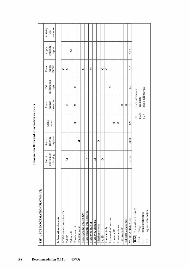
Info
rmat
ion
flow
s and
info
rmat
ion
elem
ents
SSF
→ S
CF
INFO
RM
AT
ION
FL
OW
S (1
/2)
Ev
ent
notif
icat
ion
char
ging
Serv
ice
filte
ring
resp
onse
Stat
us
repo
rt
Ass
ist
requ
est
inst
ruct
ion
Cal
l in
form
atio
n re
port
Even
t re
port
BC
SM
App
ly
char
ging
re
port
Act
ivity
te
st
resp
onse
Info
rmat
ion
elem
ents
BC
SM e
vent
cor
rela
tion
ID
O
C
all I
D
M
M
M
C
all r
esul
t
M
Cor
rela
tion
ID
O
M
O
C
ount
ers v
alue
M
Even
t spe
cific
info
BC
SM
O
Ev
ent s
peci
fic in
fo c
harg
ing
O
Ev
ent t
ype
BC
SM
M
Ev
ent t
ype
char
ging
M
Filte
ring
crite
ria
O
Le
g ID
O
O
M
isc
call
info
O
Req
uest
ed in
form
atio
n
M
Res
ourc
e ID
O
Res
ourc
e st
atus
M
SRF
avai
labl
e
O
SSF/
SRF
capa
bilit
ies
O
M
OTI
VA
TIN
G S
IBs
CH
G
Lim
it SN
U
I LC
I B
CP
CH
G
Bol
d I
E de
scrib
ed in
this
IF
CH
G
Cha
rge
SN
Stat
us n
otifi
catio
n LC
I Lo
g ca
ll in
form
atio
n
UI
Use
r int
erac
tion
Tran
s Tr
ansl
ate
BC
P B
asic
cal
l pro
cess
198 Recommendation Q.1214 (03/93)
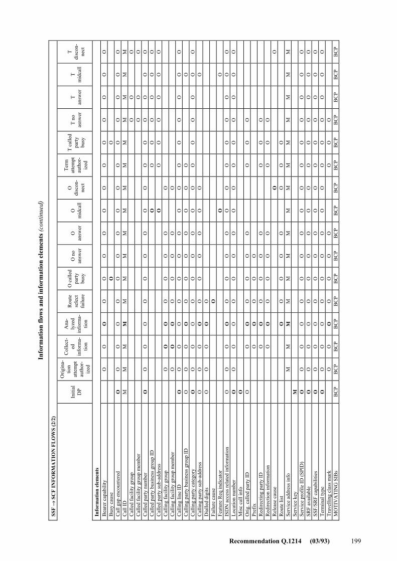
Info
rmat
ion
flow
s and
info
rmat
ion
elem
ents
(continued)
SSF
→ S
CF
INFO
RM
AT
ION
FL
OW
S (2
/2)
Initi
al
DP
Orig
ina-
tion
atte
mpt
au
thor
-iz
ed
Col
lect
-ed
in
form
a-tio
n
Ana
-ly
zed
info
rma-
tion
Rou
te
sele
ct
failu
re
O c
alle
d pa
rty
busy
O n
o an
swer
O
an
swer
O
m
idca
ll
O
disc
on-
nect
Term
at
tem
pt
auth
or-
ized
T ca
lled
party
bu
sy
T no
as
nwer
T
answ
er
T m
idca
ll
T di
scon
-ne
ct
Info
rmat
ion
elem
ents
B
eare
r cap
abili
ty
O
O
O
O
O
O
O
O
O
O
O
O
O
O
O
B
usy
caus
e
O
O
C
all g
ap e
ncou
nter
ed
O
O
O
O
O
O
O
O
O
O
O
O
O
O
O
O
Cal
l ID
M
M
M
M
M
M
M
M
M
M
M
M
M
M
M
M
C
alle
d fa
cilit
y gr
oup
O
O
O
C
alle
d fa
cilit
y gr
oup
mem
ber
O
O
O
C
alle
d pa
rty n
umbe
r O
O
O
O
O
O
O
O
O
O
O
O
O
O
O
O
C
alle
d pa
rty b
usin
ess g
roup
ID
O
O
O
O
O
O
O
C
alle
d pa
rty su
b-ad
dres
s
O
O
O
O
O
O
O
Cal
ling
faci
lity
grou
p
O
O
O
O
O
O
O
O
C
allin
g fa
cilit
y gr
oup
mem
ber
O
O
O
O
O
O
O
O
Cal
ling
line
ID
O
O
O
O
O
O
O
O
O
O
O
O
O
O
O
O
Cal
ling
party
bus
ines
s gro
up ID
O
O
O
O
O
O
O
O
O
O
O
O
C
allin
g pa
rty c
ateg
ory
O
O
O
O
O
O
O
O
O
O
O
O
O
O
O
O
Cal
ling
party
sub-
addr
ess
O
O
O
O
O
O
O
O
O
O
O
D
ialle
d di
gits
O
O
O
O
O
Failu
re c
ause
O
Feat
ure
Req
indi
cato
r
O
O
IS
DN
acc
ess r
elat
ed in
form
atio
n O
O
O
O
O
O
O
O
O
O
O
O
O
O
O
O
Lo
catio
n nu
mbe
r O
O
O
O
O
O
O
O
O
O
O
O
O
O
O
O
M
isc
call
info
O
Orig
. cal
led
party
ID
O
O
O
O
O
O
O
O
O
O
Pref
ix
O
O
O
O
O
R
edire
ctin
g pa
rty ID
O
O
O
O
O
O
O
O
O
Red
irect
ion
info
rmat
ion
O
O
O
O
O
O
O
O
O
R
elea
se c
ause
O
O
R
oute
list
O
O
O
O
O
O
O
O
Se
rvic
e ad
dres
s inf
o
M
M
M
M
M
M
M
M
M
M
M
M
M
M
M
Serv
ice
key
M
Se
rvic
e pr
ofile
ID (S
PID
) O
O
O
O
O
O
O
O
O
O
O
O
O
O
O
O
SR
F av
aila
ble
O
O
O
O
O
O
O
O
O
O
O
O
O
O
O
O
SSF/
SRF
capa
bilit
ies
O
O
O
O
O
O
O
O
O
O
O
O
O
O
O
O
Term
inal
type
O
O
O
O
O
O
O
O
O
O
O
O
O
O
O
O
Tr
avel
ling
clas
s mar
k
O
O
O
O
O
O
O
O
O
O
M
OTI
VA
TIN
G S
IBs
BC
P B
CP
BC
P B
CP
BC
P B
CP
BC
P B
CP
BC
P B
CP
BC
P B
CP
BC
P B
CP
BC
P B
CP
Recommendation Q.1214 (03/93) 199
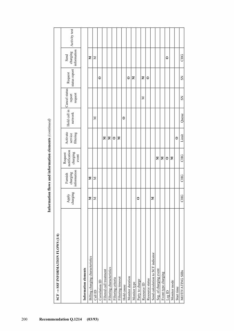
Info
rmat
ion
flow
s and
info
rmat
ion
elem
ents
(continued)
SCF
→ S
SF IN
FOR
MA
TIO
N F
LO
WS
(1/4
)
A
pply
ch
argi
ng
Furn
ish
char
ging
in
form
atio
n
Req
uest
no
tific
atio
n ch
argi
ng
even
t
Act
ivat
e se
rvic
e fil
terin
g
Hol
d ca
ll in
ne
twor
k
Can
cel s
tatu
s re
port
requ
est
Req
uest
st
atus
repo
rt
Send
ch
argi
ng
info
rmat
ion
Act
ivity
test
Info
rmat
ion
elem
ents
Bill
ing
char
ging
cha
ract
eris
tics
M
M
M
Cal
l ID
M
M
M
M
Cor
rela
tion
ID
O
Filte
red
call
treat
men
t
M
Fi
lterin
g ch
arac
teris
tics
M
Filte
ring
crite
ria
O
Filte
ring
timeo
ut
M
Hol
d ca
use
O
Mon
itor d
urat
ion
O
Mon
itor t
ype
M
Party
to c
harg
e O
R
esou
rce
ID
M
M
R
esou
rce
stat
us
O
Send
cal
cula
tion
to S
CF
indi
cato
r M
Se
g. o
f cha
rgin
g ev
ent
M
Even
t typ
e ch
argi
ng
M
Leg
ID
O
O
M
onito
r mod
e
M
St
art t
ime
O
MO
TIV
ATI
NG
SIB
s C
HG
C
HG
C
HG
Li
mit
Que
ue
SN
SN
CH
G
200 Recommendation Q.1214 (03/93)
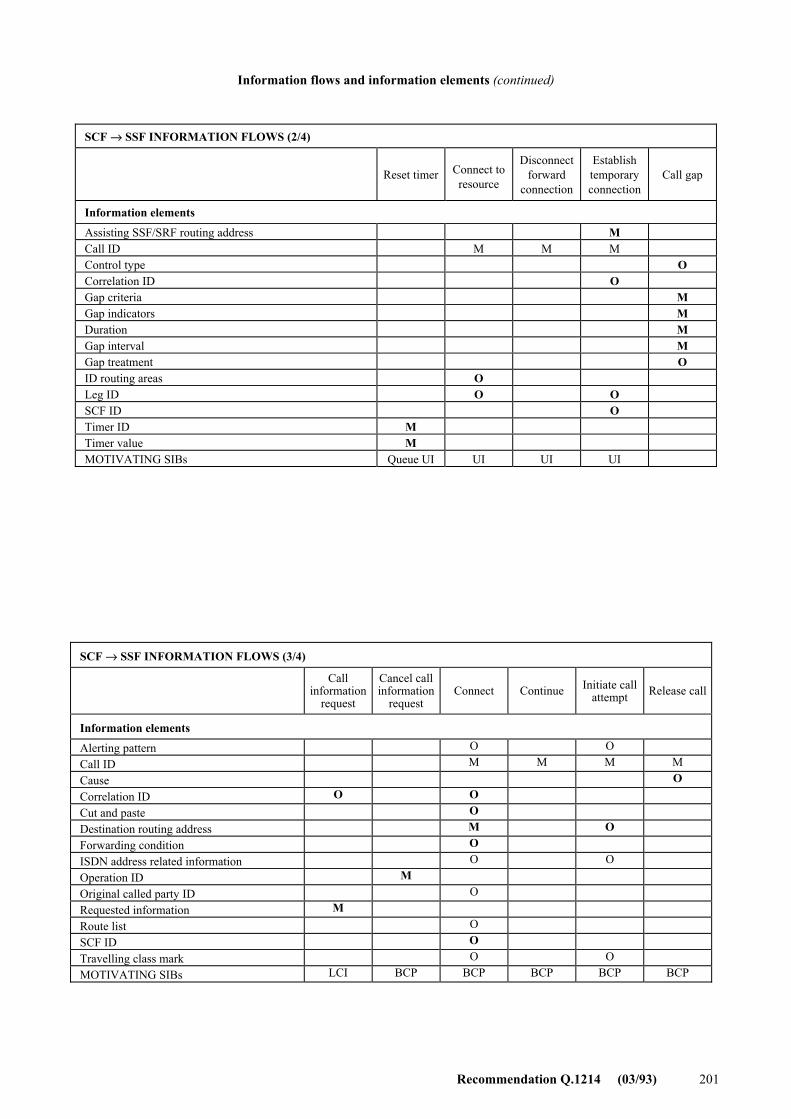
Recommendation Q.1214 (03/93) 201
Information flows and information elements (continued)
SCF → SSF INFORMATION FLOWS (2/4)
Reset timer Connect to
resource
Disconnect forward
connection
Establish temporary connection
Call gap
Information elements
Assisting SSF/SRF routing address M Call ID M M M Control type O Correlation ID O Gap criteria M Gap indicators M Duration M Gap interval M Gap treatment O ID routing areas O Leg ID O O SCF ID O Timer ID M Timer value M MOTIVATING SIBs Queue UI UI UI UI
SCF → SSF INFORMATION FLOWS (3/4)
Call information
request
Cancel call information
request
Connect
Continue Initiate call
attempt
Release call
Information elements
Alerting pattern O O Call ID M M M M Cause O Correlation ID O O Cut and paste O Destination routing address M O Forwarding condition O ISDN address related information O O Operation ID M Original called party ID O Requested information M Route list O SCF ID O Travelling class mark O O MOTIVATING SIBs LCI BCP BCP BCP BCP BCP
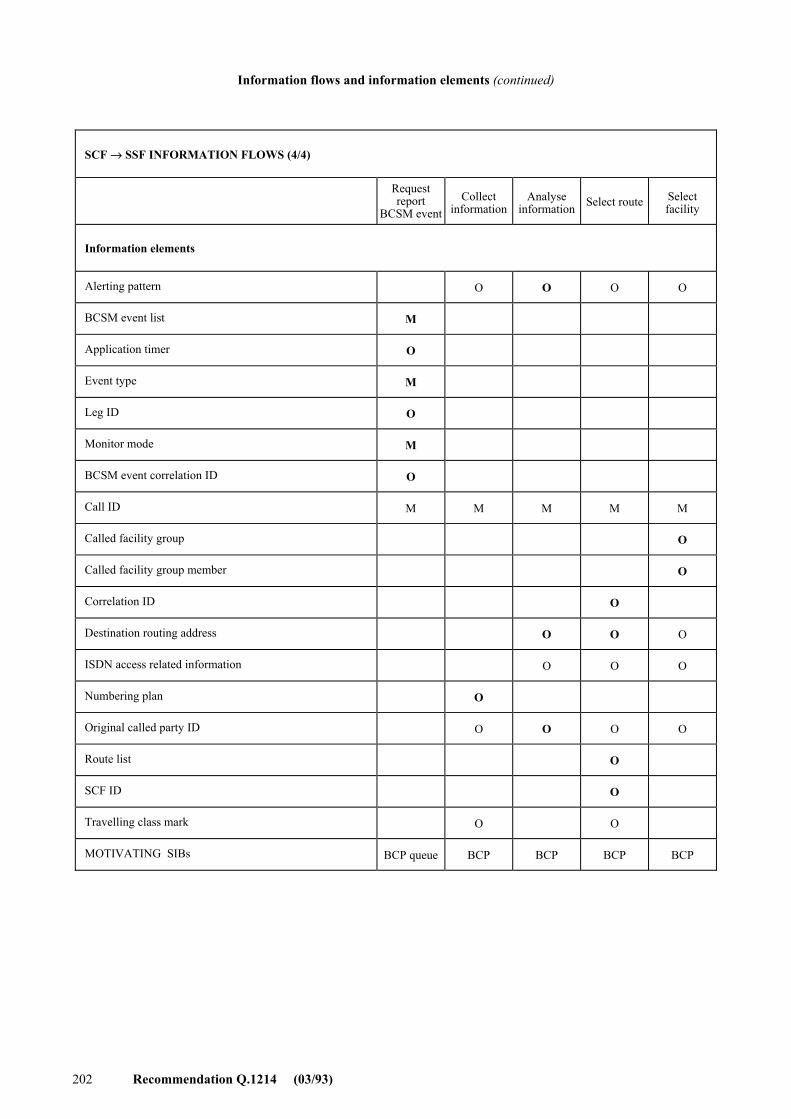
202 Recommendation Q.1214 (03/93)
Information flows and information elements (continued)
SCF → SSF INFORMATION FLOWS (4/4)
Request report
BCSM eventCollect
informationAnalyse
information Select route Select facility
Information elements
Alerting pattern O O O O
BCSM event list M
Application timer O
Event type M
Leg ID O
Monitor mode M
BCSM event correlation ID O
Call ID M M M M M
Called facility group O
Called facility group member O
Correlation ID O
Destination routing address O O O
ISDN access related information O O O
Numbering plan O
Original called party ID O O O O
Route list O
SCF ID O
Travelling class mark O O
MOTIVATING SIBs BCP queue BCP BCP BCP BCP
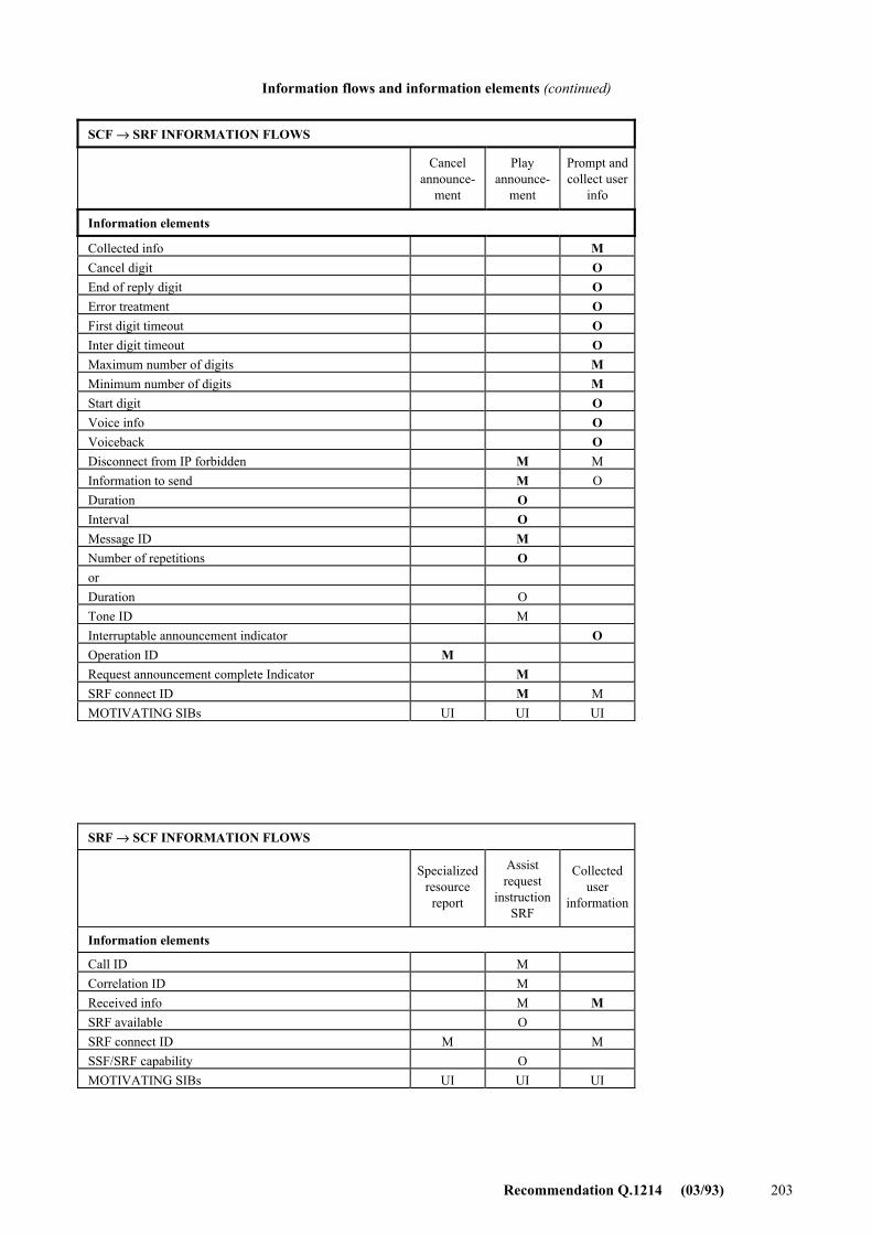
Recommendation Q.1214 (03/93) 203
Information flows and information elements (continued)
SCF → SRF INFORMATION FLOWS
Cancel announce-
ment
Play announce-
ment
Prompt and collect user
info
Information elements
Collected info M Cancel digit O End of reply digit O Error treatment O First digit timeout O Inter digit timeout O Maximum number of digits M Minimum number of digits M Start digit O Voice info O Voiceback O Disconnect from IP forbidden M M Information to send M O Duration O Interval O Message ID M Number of repetitions O or Duration O Tone ID M Interruptable announcement indicator O Operation ID M Request announcement complete Indicator M SRF connect ID M M MOTIVATING SIBs UI UI UI
SRF → SCF INFORMATION FLOWS
Specialized resource report
Assist request
instruction SRF
Collected user
information
Information elements
Call ID M Correlation ID M Received info M M SRF available O SRF connect ID M M SSF/SRF capability O MOTIVATING SIBs UI UI UI
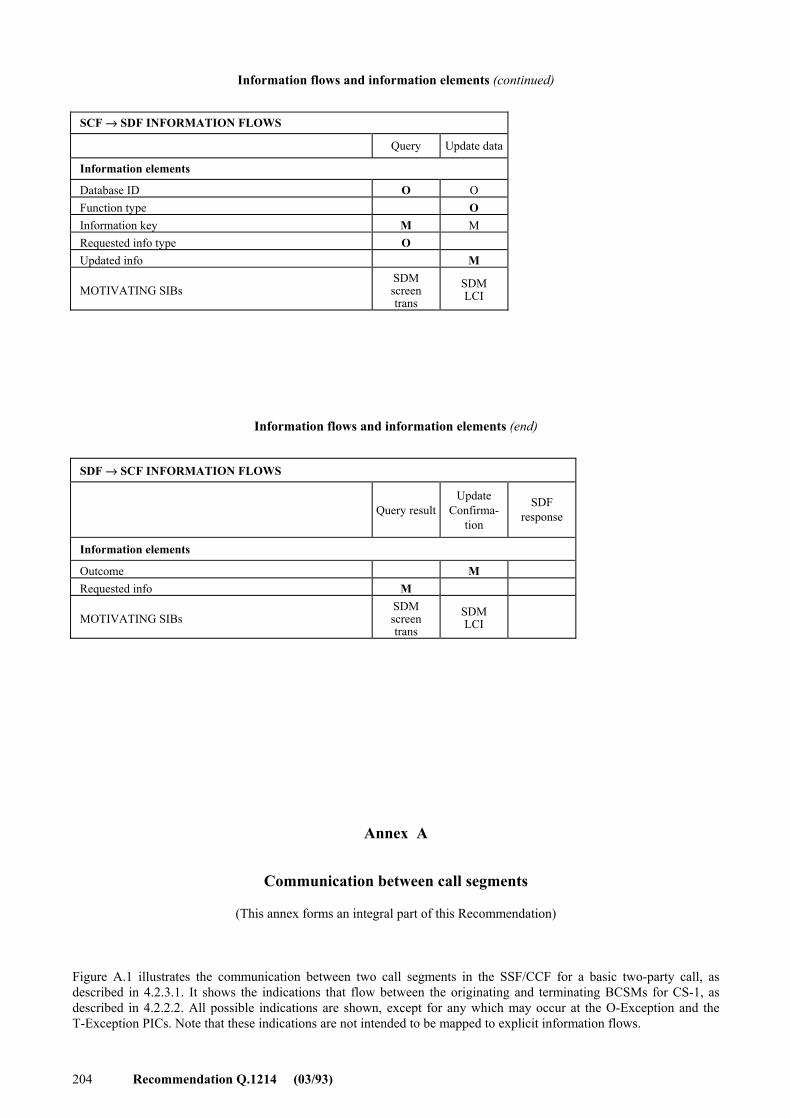
204 Recommendation Q.1214 (03/93)
Information flows and information elements (continued)
Information flows and information elements (end)
Annex A
Communication between call segments
(This annex forms an integral part of this Recommendation)
Figure A.1 illustrates the communication between two call segments in the SSF/CCF for a basic two-party call, as described in 4.2.3.1. It shows the indications that flow between the originating and terminating BCSMs for CS-1, as described in 4.2.2.2. All possible indications are shown, except for any which may occur at the O-Exception and the T-Exception PICs. Note that these indications are not intended to be mapped to explicit information flows.
SCF → SDF INFORMATION FLOWS
Query Update data
Information elements
Database ID O O Function type O Information key M M Requested info type O Updated info M MOTIVATING SIBs
SDM screen trans
SDM LCI
SDF → SCF INFORMATION FLOWS
Query result
Update Confirma-
tion
SDF response
Information elements
Outcome M Requested info M MOTIVATING SIBs
SDM screen trans
SDM LCI
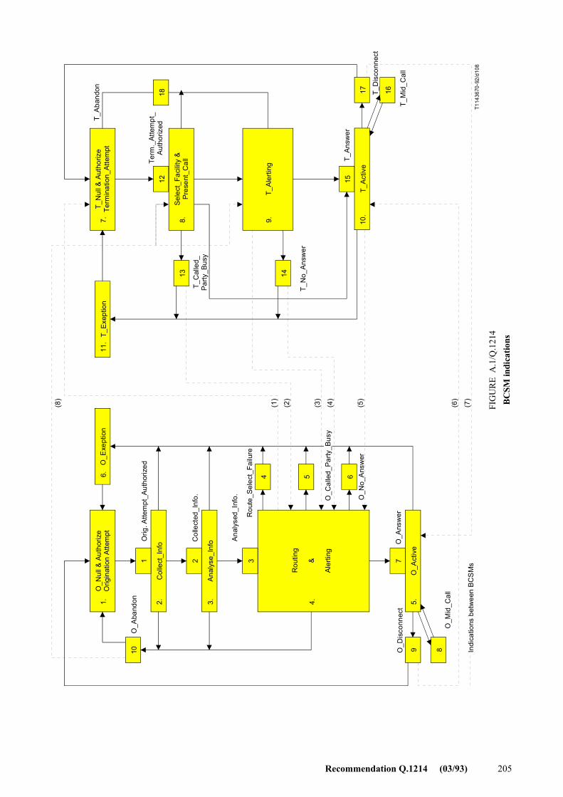
Recommendation Q.1214 (03/93) 205
10 9 8
7321
13 14
15
16171812
1. 2. 3. 4. 5.
6546.11
.7. 8. 9. 10
.
(8)
(1)
(2)
(3)
(4)
(5)
(6)
(7)
T114
3670
-92/
d108
O_A
band
on
O_N
ull &
Aut
horiz
eO
rigin
atio
n A
ttem
ptO
_Exe
ptio
n
Orig
. Atte
mpt
_Aut
horiz
ed
Col
lect
_Inf
o Col
lect
ed_I
nfo.
Ana
lyse
_Inf
o Ana
lyse
d_In
fo.
Rou
te_S
elec
t_Fa
ilure
Rou
ting
&
Aler
ting
O_C
alle
d_Pa
rty_B
usy
O_N
o_A
nsw
er
O_D
isco
nnec
t
O_M
id_C
all
O_A
ctiv
e
O_A
nsw
er
T_Ex
eptio
nT_
Aba
ndon
T_N
ull &
Aut
horiz
eTe
rmin
atio
n_At
tem
pt
Term
._At
tem
pt_
Aut
horiz
ed
T_C
alle
d_Pa
rty_B
usy
Sele
ct_F
acili
ty &
Pres
ent_
Cal
l
T_Al
ertin
g
T_N
o_An
swer
T_A
nsw
er
T_A
ctiv
e
T_D
isco
nnec
t
T_M
id_C
all
Indi
catio
ns b
etw
een
BCS
Ms
FIG
UR
E A
.1/Q
.121
4B
CSM
indi
catio
ns
FIGURE A-1/Q.1214...[D108] = 23 CM x 2 pages
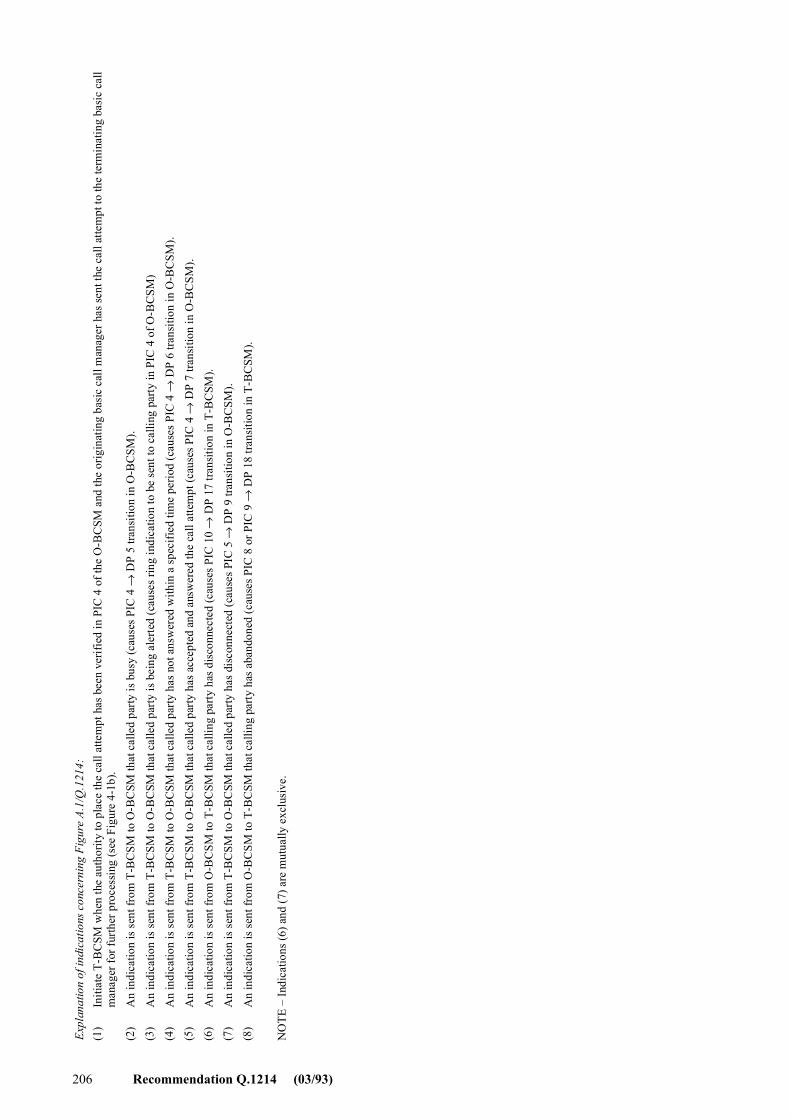
206 Recommendation Q.1214 (03/93)
Expl
anat
ion
of in
dica
tions
con
cern
ing
Figu
re A
.1/Q
.121
4:
NO
TE �
Indi
catio
ns (6
) and
(7) a
re m
utua
lly e
xclu
sive
.
Initi
ate
T-B
CSM
whe
n th
e au
thor
ity to
pla
ce th
e ca
ll at
tem
pt h
as b
een
verif
ied
in P
IC 4
of t
he O
-BC
SM a
nd th
e or
igin
atin
g ba
sic
call
man
ager
has
sent
the
call
atte
mpt
to th
e te
rmin
atin
g ba
sic
call
man
ager
for f
urth
er p
roce
ssin
g (s
ee F
igur
e 4-
1b).
An
indi
catio
n is
sent
from
T-B
CSM
to O
-BC
SM th
at c
alle
d pa
rty is
bus
y (c
ause
s PIC
4 →
DP
5 tra
nsiti
on in
O-B
CSM
).
An
indi
catio
n is
sent
from
T-B
CSM
to O
-BC
SM th
at c
alle
d pa
rty is
bei
ng a
lerte
d (c
ause
s rin
g in
dica
tion
to b
e se
nt to
cal
ling
party
in P
IC 4
of O
-BC
SM)
An
indi
catio
n is
sent
from
T-B
CSM
to O
-BC
SM th
at c
alle
d pa
rty h
as n
ot a
nsw
ered
with
in a
spec
ified
tim
e pe
riod
(cau
ses P
IC 4
→ D
P 6
trans
ition
in O
-BC
SM).
An
indi
catio
n is
sent
from
T-B
CSM
to O
-BC
SM th
at c
alle
d pa
rty h
as a
ccep
ted
and
answ
ered
the
call
atte
mpt
(cau
ses P
IC 4
→ D
P 7
trans
ition
in O
-BC
SM).
An
indi
catio
n is
sent
from
O-B
CSM
to T
-BC
SM th
at c
allin
g pa
rty h
as d
isco
nnec
ted
(cau
ses P
IC 1
0 →
DP
17 tr
ansit
ion
in T
-BC
SM).
An
indi
catio
n is
sent
from
T-B
CSM
to O
-BC
SM th
at c
alle
d pa
rty h
as d
isco
nnec
ted
(cau
ses P
IC 5
→ D
P 9
trans
ition
in O
-BC
SM).
An
indi
catio
n is
sent
from
O-B
CSM
to T
-BC
SM th
at c
allin
g pa
rty h
as a
band
oned
(cau
ses P
IC 8
or P
IC 9
→ D
P 18
tran
sitio
n in
T-B
CSM
).
(2)
(3)
(4)
(5)
(6)
(7)
(8)
(1)
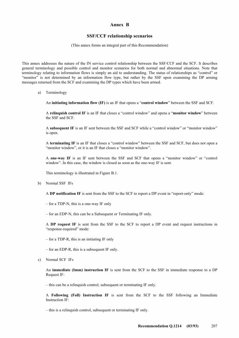
Recommendation Q.1214 (03/93) 207
Annex B
SSF/CCF relationship scenarios
(This annex forms an integral part of this Recommendation)
This annex addresses the nature of the IN service control relationship between the SSF/CCF and the SCF. It describes general terminology and possible control and monitor scenarios for both normal and abnormal situations. Note that terminology relating to information flows is simply an aid to understanding. The status of relationships as �control� or �monitor� is not determined by an information flow type, but rather by the SSF upon examining the DP arming messages returned from the SCF and examining the DP types which have been armed.
a) Terminology
An initiating information flow (IF) is an IF that opens a �control window� between the SSF and SCF.
A relinquish control IF is an IF that closes a �control window� and opens a �monitor window� between the SSF and SCF.
A subsequent IF is an IF sent between the SSF and SCF while a �control window� or �monitor window� is open.
A terminating IF is an IF that closes a �control window� between the SSF and SCF, but does not open a �monitor window�, or it is an IF that closes a �monitor window�.
A one-way IF is an IF sent between the SSF and SCF that opens a �monitor window� or �control window�. In this case, the window is closed as soon as the one-way IF is sent.
This terminology is illustrated in Figure B.1.
b) Normal SSF IFs
A DP notification IF is sent from the SSF to the SCF to report a DP event in �report-only� mode:
� for a TDP-N, this is a one-way IF only
� for an EDP-N, this can be a Subsequent or Terminating IF only.
A DP request IF is sent from the SSF to the SCF to report a DP event and request instructions in �response-required� mode:
� for a TDP-R, this is an initiating IF only
� for an EDP-R, this is a subsequent IF only.
c) Normal SCF IFs
An immediate (Imm) instruction IF is sent from the SCF to the SSF in immediate response to a DP Request IF:
� this can be a relinquish control, subsequent or terminating IF only.
A Following (Foll) Instruction IF is sent from the SCF to the SSF following an Immediate Instruction IF:
� this is a relinquish control, subsequent or terminating IF only.
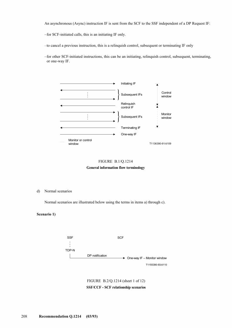
208 Recommendation Q.1214 (03/93)
An asynchronous (Async) instruction IF is sent from the SCF to the SSF independent of a DP Request IF:
� for SCF-initiated calls, this is an initiating IF only.
� to cancel a previous instruction, this is a relinquish control, subsequent or terminating IF only
� for other SCF-initiated instructions, this can be an initiating, relinquish control, subsequent, terminating, or one-way IF.
. . . .
. . . .
T1136390-91/d109
Initiating IF
Subsequent IFs Controlwindow
Monitorwindow
Relinquishcontrol IF
Terminating IF
Subsequent IFs
One-way IF
Monitor or controlwindow
FIGURE B.1/Q.1214General information flow terminology
FIGURE B.1/Q.1214...[D109] = 8 CM
d) Normal scenarios
Normal scenarios are illustrated below using the terms in items a) through c).
Scenario 1)
T1155390-93/d110
SSF
TDP-N
SCF
One-way IF � Monitor window
FIGURE B.2/Q.1214 (sheet 1 of 12)SSF/CCF - SCF relationship scenarios
DP notification
FIGURE B.2/Q.1214...[D110] = 5,5 CM
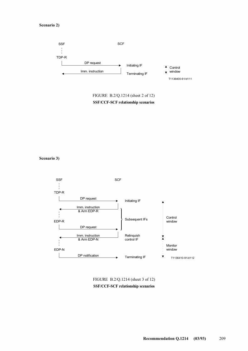
Recommendation Q.1214 (03/93) 209
Scenario 2)
T1136400-91/d111
SSF SCF
TDP-R
DP request
Imm. instructionControlwindow
Initiating IF
Terminating IF
FIGURE B.2/Q.1214 (sheet 2 of 12)SSF/CCF-SCF relationship scenarios
FIGURE B.2/Q.1214...[D111] = 5 CM
Scenario 3)
T1136410-91/d112
SSF SCF
TDP-R
EDP-R
EDP-N
DP request
Imm. instruction& Arm EDP-R
DP request
DP notification
Imm. instruction& Arm EDP-N
Initiating IF
Subsequent IFs
Relinquishcontrol IF
Terminating IF
Controlwindow
Monitorwindow
FIGURE B.2/Q.1214 (sheet 3 of 12)SSF/CCF-SCF relationship scenarios
FIGURE B.2/Q.1214...[D112] = 9.5 CM
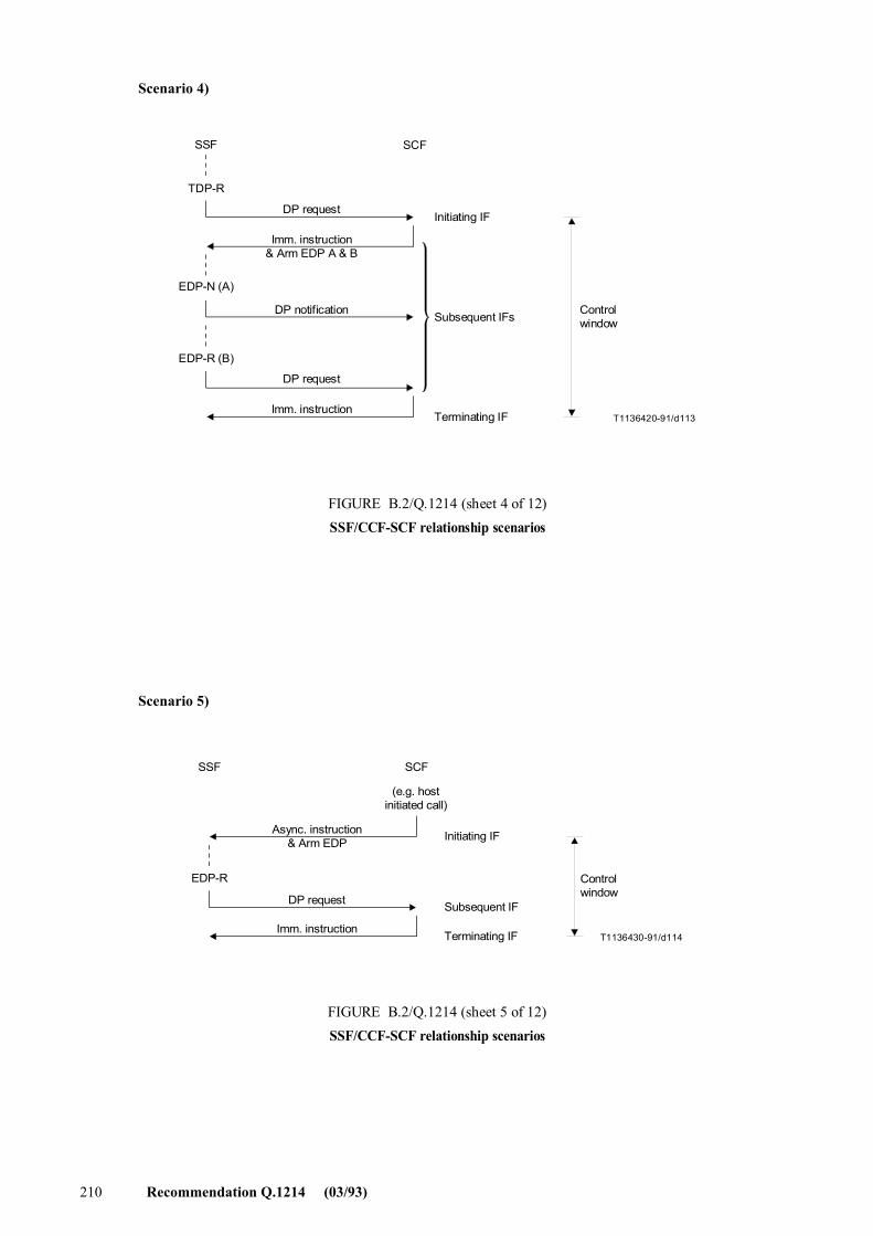
210 Recommendation Q.1214 (03/93)
Scenario 4)
T1136420-91/d113
SSF SCF
TDP-R
EDP-N (A)
EDP-R (B)
Controlwindow
Initiating IF
Subsequent IFs
Terminating IF
DP request
Imm. instruction& Arm EDP A & B
DP notification
DP request
Imm. instruction
FIGURE B.2/Q.1214 (sheet 4 of 12)SSF/CCF-SCF relationship scenarios
FIGURE B.2/Q.1214...[D113] = 9.5 CM
Scenario 5)
T1136430-91/d114
SSF SCF
(e.g. hostinitiated call)
Controlwindow
Initiating IF
Subsequent IF
Terminating IF
EDP-R
Async. instruction& Arm EDP
DP request
Imm. instruction
FIGURE B.2/Q.1214 (sheet 5 of 12)SSF/CCF-SCF relationship scenarios
FIGURE B.2/Q.1214...[D114] = 6.5 CM
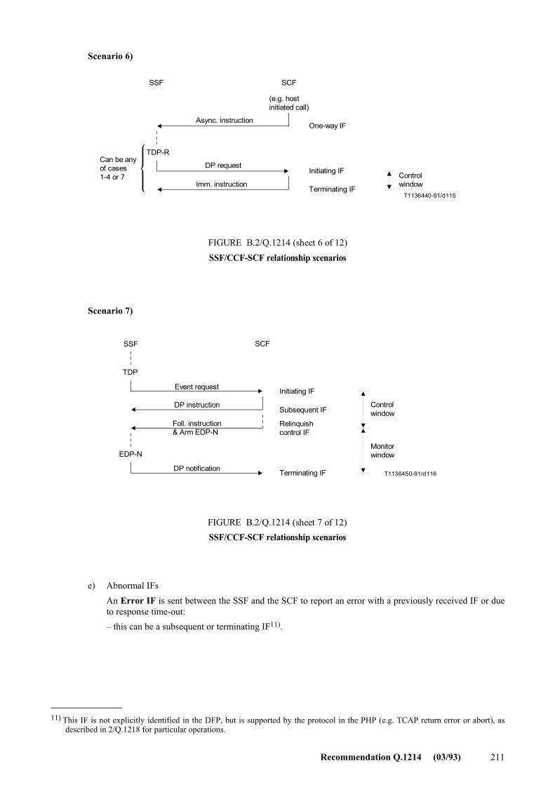
Recommendation Q.1214 (03/93) 211
Scenario 6)
T1136440-91/d115
SSF SCF
TDP-RCan be anyof cases1-4 or 7
(e.g. hostinitiated call)
Async. instruction
DP request
Imm. instruction
One-way IF
Initiating IF
Terminating IF
Controlwindow
FIGURE B.2/Q.1214 (sheet 6 of 12)SSF/CCF-SCF relationship scenarios
FIGURE B.2/Q.1214...[D115] = 7 CM
Scenario 7)
T1136450-91/d116
SSF SCF
TDP
EDP-N
Controlwindow
Monitorwindow
Initiating IF
Subsequent IF
Relinquishcontrol IF
Terminating IF
Event request
DP instruction
Foll. instruction& Arm EDP-N
DP notification
FIGURE B.2/Q.1214 (sheet 7 of 12)SSF/CCF-SCF relationship scenarios
FIGURE B.2/Q.1214...[D116] = 7.5 CM e) Abnormal IFs
An Error IF is sent between the SSF and the SCF to report an error with a previously received IF or due to response time-out: � this can be a subsequent or terminating IF11).
_______________ 11) This IF is not explicitly identified in the DFP, but is supported by the protocol in the PHP (e.g. TCAP return error or abort), as
described in 2/Q.1218 for particular operations.
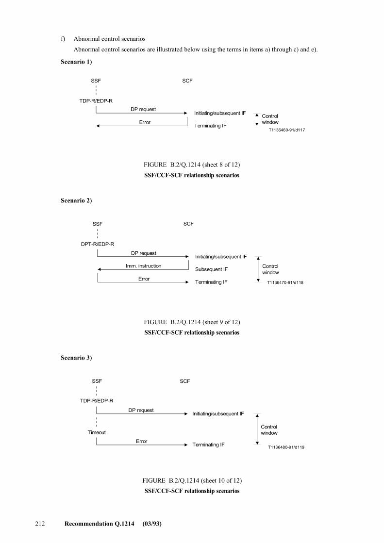
212 Recommendation Q.1214 (03/93)
f) Abnormal control scenarios
Abnormal control scenarios are illustrated below using the terms in items a) through c) and e).
Scenario 1)
T1136460-91/d117
SSF SCF
TDP-R/EDP-RDP request
ErrorControlwindow
Initiating/subsequent IF
Terminating IF
FIGURE B.2/Q.1214 (sheet 8 of 12)SSF/CCF-SCF relationship scenarios
FIGURE B.2/Q.1214...[D117] = 5.5 CM
Scenario 2)
T1136470-91/d118
SSF SCF
DPT-R/EDP-R
Controlwindow
Initiating/subsequent IF
Subsequent IF
Terminating IF
DP request
Imm. instruction
Error
FIGURE B.2/Q.1214 (sheet 9 of 12)SSF/CCF-SCF relationship scenarios
FIGURE B.2/Q.1214...[D118] = 6 CM
Scenario 3)
T1136480-91/d119
SSF SCF
TDP-R/EDP-R
Timeout
DP request
Error
Initiating/subsequent IF
Terminating IF
Controlwindow
FIGURE B.2/Q.1214 (sheet 10 of 12)SSF/CCF-SCF relationship scenarios
FIGURE B.2/Q.1214...[D119] = 6.5 CM
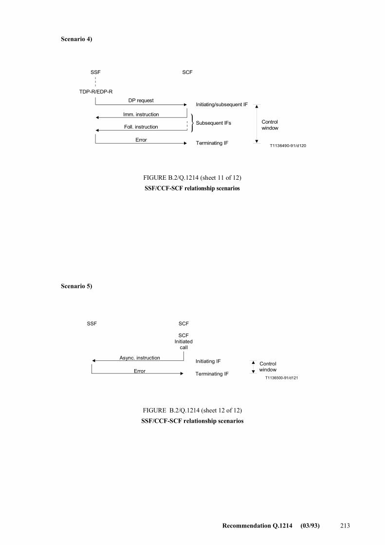
Recommendation Q.1214 (03/93) 213
Scenario 4)
T1136490-91/d120
SSF SCF
TDP-R/EDP-R
Controlwindow
Initiating/subsequent IF
Subsequent IFs
Terminating IF
DP request
Imm. instruction
Foll. instruction
Error
FIGURE B.2/Q.1214 (sheet 11 of 12)SSF/CCF-SCF relationship scenarios
FIGURE B.2/Q.1214...[D120] = 6.5 CM
Scenario 5)
T1136500-91/d121
ControlwindowError
Async. instructionInitiating IF
Terminating IF
SCFInitiated
call
SSF SCF
FIGURE B.2/Q.1214 (sheet 12 of 12)SSF/CCF-SCF relationship scenarios
FIGURE B.2/Q.1214...[D121] = 5.5 CM
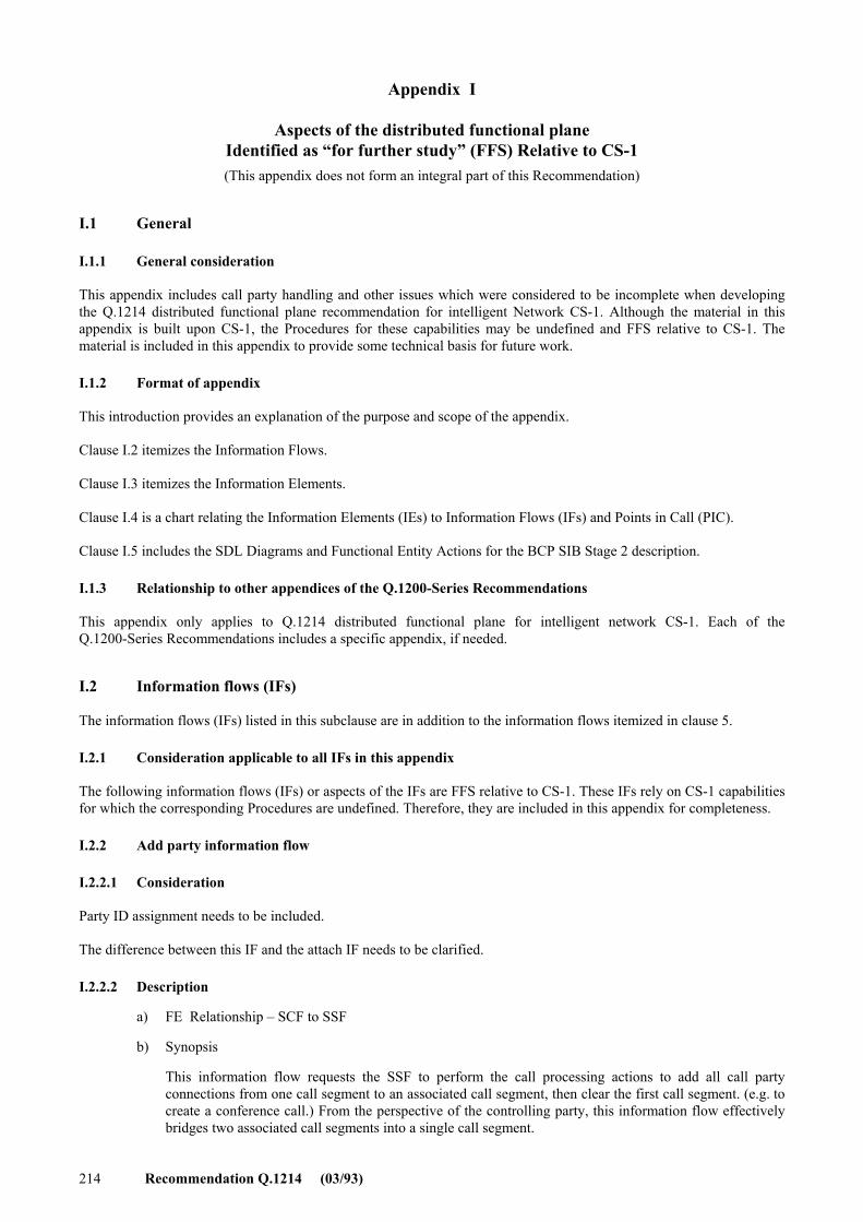
214 Recommendation Q.1214 (03/93)
Appendix I
Aspects of the distributed functional plane Identified as �for further study� (FFS) Relative to CS-1 (This appendix does not form an integral part of this Recommendation)
I.1 General
I.1.1 General consideration
This appendix includes call party handling and other issues which were considered to be incomplete when developing the Q.1214 distributed functional plane recommendation for intelligent Network CS-1. Although the material in this appendix is built upon CS-1, the Procedures for these capabilities may be undefined and FFS relative to CS-1. The material is included in this appendix to provide some technical basis for future work.
I.1.2 Format of appendix
This introduction provides an explanation of the purpose and scope of the appendix.
Clause I.2 itemizes the Information Flows.
Clause I.3 itemizes the Information Elements.
Clause I.4 is a chart relating the Information Elements (IEs) to Information Flows (IFs) and Points in Call (PIC).
Clause I.5 includes the SDL Diagrams and Functional Entity Actions for the BCP SIB Stage 2 description.
I.1.3 Relationship to other appendices of the Q.1200-Series Recommendations
This appendix only applies to Q.1214 distributed functional plane for intelligent network CS-1. Each of the Q.1200-Series Recommendations includes a specific appendix, if needed.
I.2 Information flows (IFs)
The information flows (IFs) listed in this subclause are in addition to the information flows itemized in clause 5.
I.2.1 Consideration applicable to all IFs in this appendix
The following information flows (IFs) or aspects of the IFs are FFS relative to CS-1. These IFs rely on CS-1 capabilities for which the corresponding Procedures are undefined. Therefore, they are included in this appendix for completeness.
I.2.2 Add party information flow
I.2.2.1 Consideration
Party ID assignment needs to be included.
The difference between this IF and the attach IF needs to be clarified.
I.2.2.2 Description
a) FE Relationship � SCF to SSF
b) Synopsis
This information flow requests the SSF to perform the call processing actions to add all call party connections from one call segment to an associated call segment, then clear the first call segment. (e.g. to create a conference call.) From the perspective of the controlling party, this information flow effectively bridges two associated call segments into a single call segment.
Recommendation Q.1214 (03/93) 215
c) Information elements
Originating call ID (O) Destination call ID (O)
d) IE description
For further study.
e) Mapping to FE model(s)
For further study.
I.2.3 Attach information flow
I.2.3.1 Consideration
The difference between this IF and the add party IF needs to be clarified.
I.2.3.2 Description
a) FE Relationship � SCF to SSF
b) Synopsis
This information flow enables the SCF to request the SSF to include a leg in the current relationship instance. The leg is transferred from another relationship instance, from which it was removed using the detach information flow. Notice that detach may also be executed after attach using the same absolute identifier.
c) Information elements
Call ID (M) NewLegID (M) Correlation identifier (M)
d) IE description
As previously described.
e) Mapping to FE model(s)
SSF Precondition:
1) The leg is in a detached state for this IN-SSM instance.
SSF Postcondition:
1) The leg is in an attached state for this IN-SSM instance.
The relation of the attached state to either the pending or unconnected state is for further study.
I.2.4 Change parties information flow
I.2.4.1 Description
a) FE Relationship � SCF to SSF
b) Synopsis
This information flow requests the SSF to perform the call processing actions to change a particular party connection from one call segment to an associated call segment. From the perspective of the particular call party, this information flow effectively places the first call segment on hold and retrieves the associated call segment from hold.
c) Information elements
Call ID (O) Target call ID (M) Leg to be connected (M)
216 Recommendation Q.1214 (03/93)
d) IE description
Target Call ID specifies the call to be reactivated.
Leg to be connected specifies the party within the reactivated call which is to be connected.
e) Mapping to FE model(s)
For further study.
I.2.5 Detach information flow
I.2.5.1 Consideration
The difference between this IF and the release call party IF needs to be clarified.
I.2.5.2 Description
a) FE Relationship � SCF to SSF
b) Synopsis
This information flow enables the SCF to request the SSF to remove a leg from one relationship instance and to assign it an absolute (i.e. single network-wide) identifier (Correlation identifier), so that it can be transferred to another relationship instance, to which the leg was/will be attached by means of the attach information flow using the same absolute identifier.
c) Information elements
Call ID (M) LegIDtobeDetached (M) Correlation Identifier (M)
d) IE description
As previously described.
e) Mapping to FE model(s)
SSF Precondition:
1) The leg is either in pending or unconnected state.
SSF Postcondition:
1) The leg is in a detached state for this IN-SSM instance.
I.2.6 Hold call party connection information flow
I.2.6.1 Description
a) FE Relationship: SCF to SSF
b) Synopsis
This information flow requests the SSF to perform the call processing actions to place a particular party connection in a call segment on hold, as indicated by the controlling party or by the SCF.
c) Information elements
Call ID (O) Leg ID (M)
d) IE description
As previously defined with the following additions.
Leg ID specifies the party to be placed on hold.
e) Mapping to FE model(s)
For further study.
Recommendation Q.1214 (03/93) 217
I.2.7 Initiate call attempt information flow (For case of more than 1 party)
I.2.7.1 Consideration
This information flow is included in the main body of this Recommendation, for the case of creating a call to one call party. The IF is listed in this Appendix for the case of creating a call to more than one Party, in the same call, which for CS-1 is for further study.
I.2.7.2 Description
a) FE Relationship: SCF to SSF
b) Synopsis
This IF is used to request the SSF to create a new call to one or more call parties using address information provided by the SCF (e.g. predefined conference call)
c) Information elements
Call ID (M) Destination routing address (O) Destination address (O) Alerting pattern (O) Timeout (O) Leg ID created (O)
d) IE description:
As previously defined.
The usage of the �Timeout� IE needs clarification.
Leg ID created defaults to �B party�, if no value is supplied.
e) Mapping to FE model(s)
This information flow applies outside the context of an existing relationship between the SCF and the SSF, or within the context of an existing control relationship for a given two-party or multi-party call segment.
SCF Precondition:
l) A SLPI has been invoked, and
2) The SLPI invokes an Initiate Call Attempt functional routine.
SCF Postcondition:
1) SLPI execution may continue.
SSF Precondition:
� Outside the context of an existing relationship:
1) Destination information and optional call setup information is provided by the SCF.
� Within the context of an existing control relationship
1) Call origination attempt has been initiated, and
2) Basic call processing is suspended at a DP, and
3) Destination information and optional call setup information is provided by the SCF.
SSF Postcondition:
1) A new originating call segment is initiated, and
2) If within the context of an existing control relationship, the new call segment is associated with an existing call segment, and
3) DP 3-7 or 10, or an exception is encountered.
218 Recommendation Q.1214 (03/93)
I.2.8 Reconnect information flow
I.2.8.1 Description
a) FE Relationship: SCF to SSF
b) Synopsis
This information flow requests the SSF to perform the call processing actions to retrieve a particular party connection in a call segment from hold, as indicated by the controlling party or by the SCF. The information flow is the inverse of the HoldCallPartyConnection information flow for a single call party connection.
c) Information elements
Call ID (O) Held leg ID (M)
d) IE description
As previously defined with the following additions.
Held Leg ID specifies the identity of the party which is currently on hold and which is to be re-connected.
e) Mapping to FE model(s)
For further study.
I.2.9 Release call party connection information flow
I.2.9.1 Consideration
The difference between this IF and the detach IF needs to be clarified.
I.2.9.2 Description
a) FE Relationship: SCF to SSF
b) Synopsis
This information flow requests the SSF to perform the call processing actions to release a call party connection from a call segment, or to release all call party connections from the call segment, effectively releasing the call segment.
c) Information elements
Leg to be released (M) Call ID (O) Release cause (O)
d) IE description
As previously defined with the following additions.
Leg to be released specifies the party to be released.
Release cause specifies the reason for the release, and is used by the SSF to apply the appropriate treatment.
e) Mapping to FE model(s)
For further study.
I.3 Information elements (IE)
The information elements (IEs) listed in this subclause are additional IEs for the information flows itemized in 5.
1.3.1 Considerations applicable to all IEs in this appendix
The following information elements (IEs) are FFS relative to CS-1. These IEs rely on CS-1 capabilities for which the corresponding Procedures are undefined. Therefore, they are included in this appendix for completeness.

Recommendation Q.1214 (03/93) 219
I.3.2 Leg ID created IE (from Analyze Information IF)
I.3.2.1 Description
Leg ID created (O)
Leg ID created. The default value identifies the �B-party�.
1.3.3 Leg ID created IE (from Connect IF)
I.3.3.1 Description
Leg ID created (O)
Leg ID created defaults to the �B party�, if no value is supplied.
I.3.4 Leg ID created IE (from initiate call attempt IF)
I.3.4.1 Description
Leg ID created (O)
Leg ID created defaults to the �B party�, if no value is supplied.
I.3.5 Leg ID created IE (from select facility IF)
I.3.5.1 Description
Leg ID created (O)
As previously defined.
I.3.6 Leg ID created IE (from select route IF)
I.3.6.1 Description
Leg ID created (O)
As previously defined.
I.3.7 Leg 1 IE (from initial request instruction IF)
I.3.7.1 Description
Leg 1 (O)
Leg 1 refers to the calling party. This is an operator optional IE. it in used when there is a need to address the individual parties in a call. This IE has two sub-elements:
� Leg ID
� Leg status (connected...)
When the Leg I IE is not present, a default value of �A party� and �Pending� is assumed for Leg ID and LegStatus.
I.3.8 Leg 2 IE (from initial request instruction IF)
I.3.8.1 Description
Leg 2 (O)
Leg 2 refers to the called party. This is an operator optional IE. It is used when there is a need to address the individual parties in a call. This IE has two sub-elements:
� Leg ID
� Leg status (connected...)
Leg 2 is network operator optional and can only be sent if the T_MidCall or O_Midcall_DP is encountered.
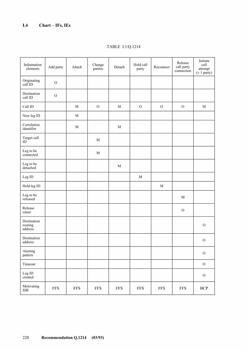
220 Recommendation Q.1214 (03/93)
I.4 Chart � IFs, IEs
TABLE I.1/Q.1214
Information
elements Add party Attach
Change parties Detach
Hold call
party Reconnect Release
call party connection
Initiate call
attempt (> 1 party)
Originating call ID O
Destination call ID O
Call ID M O M O O O M
New leg ID M
Correlation identifier
M M
Target call ID
M
Leg to be connected
M
Leg to be detached
M
Leg ID M
Held leg ID M
Leg to be released
M
Release cause
O
Destination routing address
O
Destination address
O
Alerting pattern
O
Timeout O
Leg ID created
O
Motivating SIB FFS FFS FFS FFS FFS FFS FFS BCP
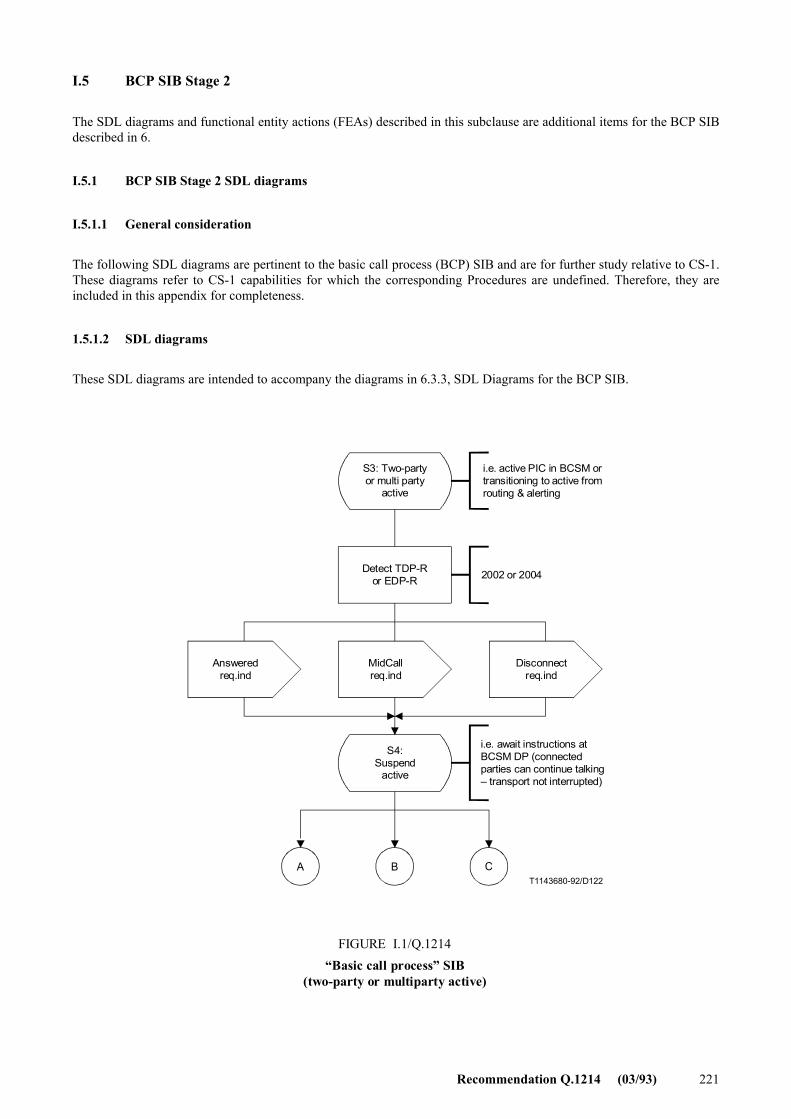
Recommendation Q.1214 (03/93) 221
I.5 BCP SIB Stage 2
The SDL diagrams and functional entity actions (FEAs) described in this subclause are additional items for the BCP SIB described in 6.
I.5.1 BCP SIB Stage 2 SDL diagrams
I.5.1.1 General consideration
The following SDL diagrams are pertinent to the basic call process (BCP) SIB and are for further study relative to CS-1. These diagrams refer to CS-1 capabilities for which the corresponding Procedures are undefined. Therefore, they are included in this appendix for completeness.
1.5.1.2 SDL diagrams
These SDL diagrams are intended to accompany the diagrams in 6.3.3, SDL Diagrams for the BCP SIB.
A B CT1143680-92/D122
S3: Two-partyor multi party
active
i.e. active PIC in BCSM ortransitioning to active fromrouting & alerting
Detect TDP-Ror EDP-R 2002 or 2004
Answeredreq.ind
MidCallreq.ind
Disconnectreq.ind
S4:Suspend
active
i.e. await instructions atBCSM DP (connectedparties can continue talking� transport not interrupted)
FIGURE I.1/Q.1214�Basic call process� SIB
(two-party or multiparty active)
FIGURE I.1/Q.1214...[D122] = 14 CM
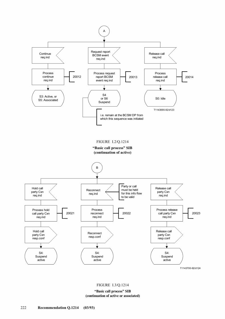
222 Recommendation Q.1214 (03/93)
A
T1143690-92/d123
20012 20013 20014
Continuereq.ind
Request reportBCSM event
req.ind
Release callreq.ind
Processcontinuereq.ind
S3: Active, orS5: Associated
Process requestreport BCSMevent req.ind
S4or S6
SuspendS0: Idle
Processrelease call
req.ind
i.e. remain at the BCSM DP fromwhich this sequence was initiated
FIGURE I.2/Q.1214�Basic call process� SIB(continuation of active) FIGURE I.2/Q.1214...[D123] = 11.5 CM
B
T1143700-92/d124
20021 20022 20023
Hold callparty Cxn
req.ind
Reconnectreq.ind
Party or callmust be heldfor this info flowto be valid
Release callparty Cxn
req.ind
Process holdcall party Cxn
req.ind
Processreconnect
req.ind
Process releasecall party Cxn
req.ind
Hold callparty Cxnresp.conf
Release callparty Cxnresp.conf
Reconnectresp.conf
S4:Suspend
active
S4:Suspend
active
S4:Suspend
active
FIGURE I.3/Q.1214�Basic call process� SIB
(continuation of active or associated)
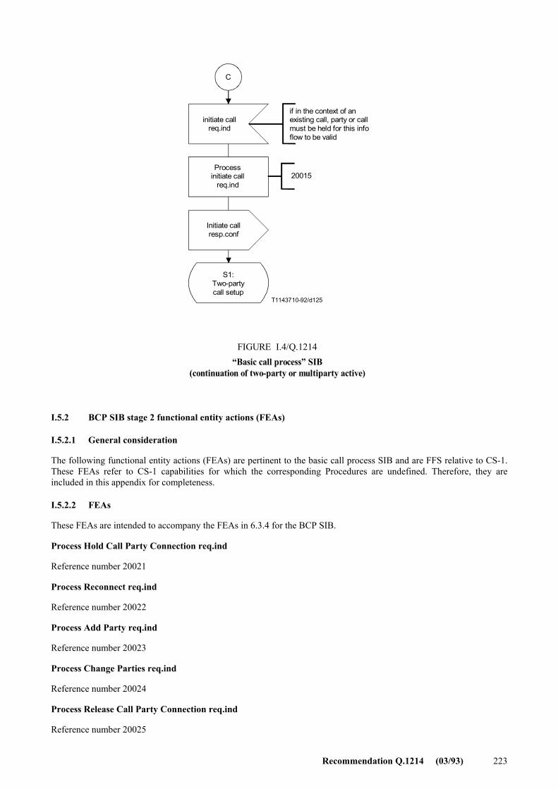
Recommendation Q.1214 (03/93) 223
C
T1143710-92/d125
20015
initiate callreq.ind
Processinitiate call
req.ind
Initiate callresp.conf
S1:Two-partycall setup
FIGURE I.4/Q.1214�Basic call process� SIB
(continuation of two-party or multiparty active)
if in the context of anexisting call, party or callmust be held for this infoflow to be valid
FIGURE I.4/Q.1214...[D125] =12 CM
I.5.2 BCP SIB stage 2 functional entity actions (FEAs)
I.5.2.1 General consideration
The following functional entity actions (FEAs) are pertinent to the basic call process SIB and are FFS relative to CS-1. These FEAs refer to CS-1 capabilities for which the corresponding Procedures are undefined. Therefore, they are included in this appendix for completeness.
I.5.2.2 FEAs
These FEAs are intended to accompany the FEAs in 6.3.4 for the BCP SIB.
Process Hold Call Party Connection req.ind
Reference number 20021
Process Reconnect req.ind
Reference number 20022
Process Add Party req.ind
Reference number 20023
Process Change Parties req.ind
Reference number 20024
Process Release Call Party Connection req.ind
Reference number 20025
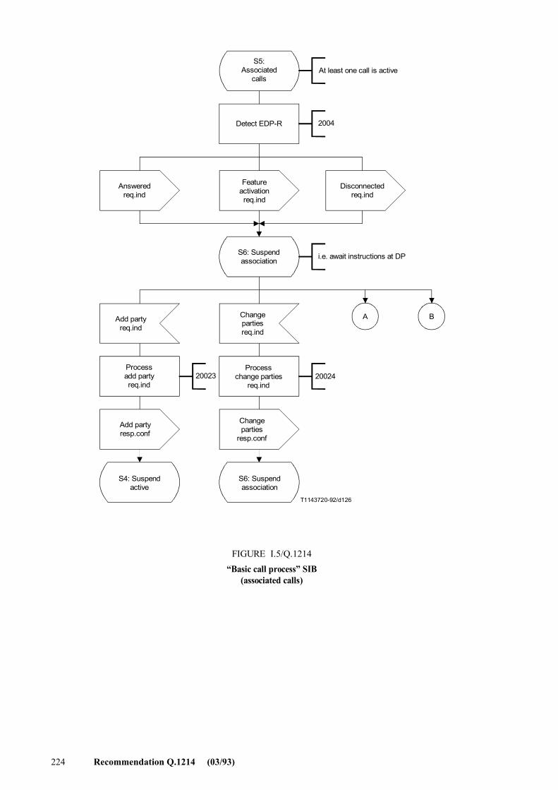
224 Recommendation Q.1214 (03/93)
2002420023
A B
T1143720-92/d126
S5:Associated
calls
Detect EDP-R
At least one call is active
2004
Answeredreq.ind
Featureactivationreq.ind
Disconnectedreq.ind
S6: Suspendassociation i.e. await instructions at DP
Add partyreq.ind
Changepartiesreq.ind
Processadd partyreq.ind
Processchange parties
req.ind
Add partyresp.conf
Changeparties
resp.conf
S4: Suspendactive
S6: Suspendassociation
FIGURE I.5/Q.1214�Basic call process� SIB
(associated calls)


Printed in Switzerland
Geneva, 1993