Embed Size (px)
Citation preview
© 2012 Agilent Technologies
Wireless Communications
Greater insight. Greater confidence. Accelerate next-generation wireless.
It’s Time for TD-LTE
Presented by: Bai Ying, Agilent Technologies
© 2012 Agilent Technologies
Wireless Communications
Greater insight. Greater confidence.
Accelerate next-generation wireless.
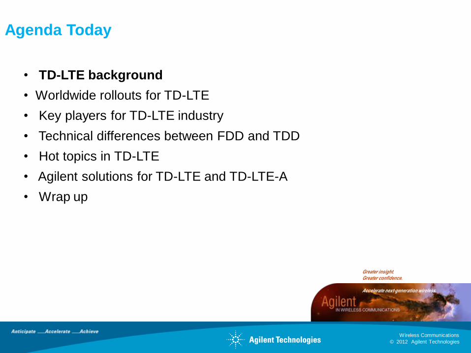
Agenda Today
• TD-LTE background
• Worldwide rollouts for TD-LTE
• Key players for TD-LTE industry
• Technical differences between FDD and TDD
• Hot topics in TD-LTE
• Agilent solutions for TD-LTE and TD-LTE-A
• Wrap up
© 2012 Agilent Technologies
Wireless Communications
Greater insight. Greater confidence.
Accelerate next-generation wireless.
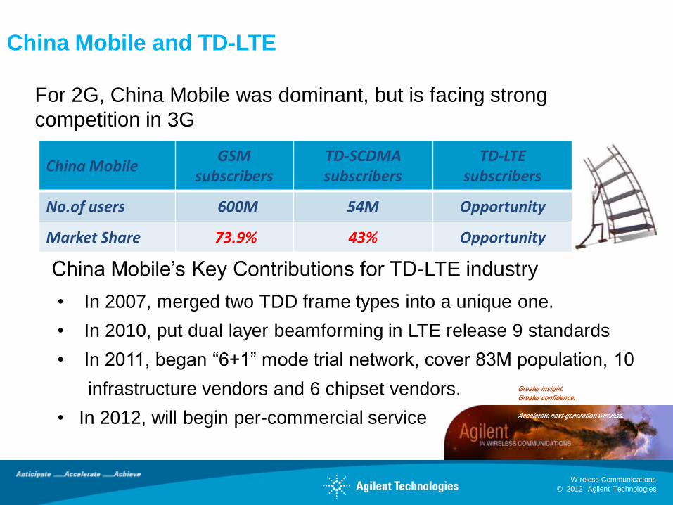
China Mobile and TD-LTE
China MobileGSM
subscribersTD-SCDMA subscribers
TD-LTE subscribers
No.of users 600M 54M Opportunity
Market Share 73.9% 43% Opportunity
For 2G, China Mobile was dominant, but is facing strong
competition in 3G
China Mobile’s Key Contributions for TD-LTE industry
• In 2007, merged two TDD frame types into a unique one.
• In 2010, put dual layer beamforming in LTE release 9 standards
• In 2011, began “6+1” mode trial network, cover 83M population, 10
infrastructure vendors and 6 chipset vendors.
• In 2012, will begin per-commercial service
© 2012 Agilent Technologies
Wireless Communications
Greater insight. Greater confidence.
Accelerate next-generation wireless.
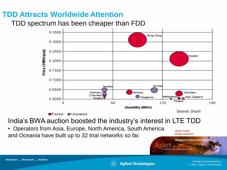
TDD Attracts Worldwide Attention TDD spectrum has been cheaper than FDD
Source: Ovum
India’s BWA auction boosted the industry’s interest in LTE TDD• Operators from Asia, Europe, North America, South America
and Oceania have built up to 32 trial networks so far.
© 2012 Agilent Technologies
Wireless Communications
Greater insight. Greater confidence.
Accelerate next-generation wireless.
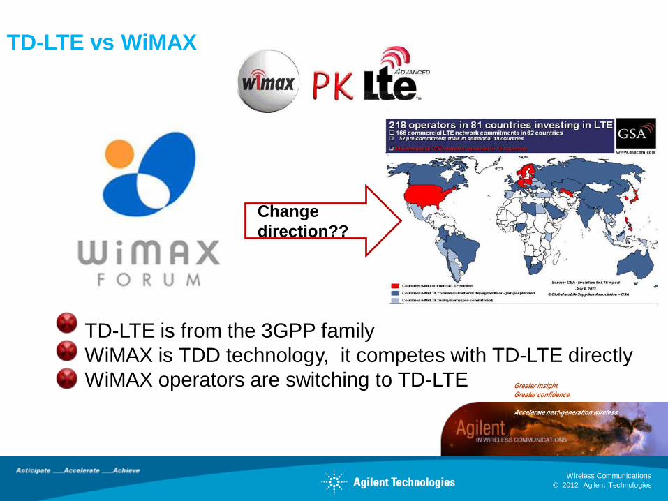
TD-LTE vs WiMAX
Change
direction??
TD-LTE is from the 3GPP family
WiMAX is TDD technology, it competes with TD-LTE directly
WiMAX operators are switching to TD-LTE

© 2012 Agilent Technologies
Wireless Communications
Greater insight. Greater confidence.
Accelerate next-generation wireless.
Agenda Today
• TD-LTE background
• Worldwide rollouts for TD-LTE
• Key players for TD-LTE industry
• Technical differences between FDD and TDD
• Hot topics in TD-LTE
• Agilent solutions for TD-LTE and TD-LTE-A
• Wrap up
© 2012 Agilent Technologies
Wireless Communications
Greater insight. Greater confidence.
Accelerate next-generation wireless.
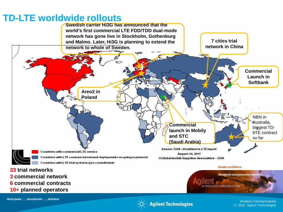
TD-LTE worldwide rollouts
7 cities trial
network in China
Commercial
Launch in
Softbank
Commercial
launch in Mobily
and STC
(Saudi Arabia)
NBN in
Australia,
biggest TD-
LTE contract
so far
Swedish carrier Hi3G has announced that the
world's first commercial LTE FDD/TDD dual-mode
network has gone live in Stockholm, Gothenburg
and Malmo. Later, Hi3G is planning to extend the
network to whole of Sweden.
Areo2 in
Poland
33 trial networks
3 commercial network
6 commercial contracts
10+ planned operators
© 2012 Agilent Technologies
Wireless Communications
Greater insight. Greater confidence.
Accelerate next-generation wireless.
Agenda Today
• TD-LTE background
• Worldwide rollouts for TD-LTE
• Key players for TD-LTE industry
• Technical differences between FDD and TDD
• Hot topics in TD-LTE
• Agilent solutions for TD-LTE and TD-LTE-A
• Wrap up
© 2012 Agilent Technologies
Wireless Communications
Greater insight. Greater confidence.
Accelerate next-generation wireless.
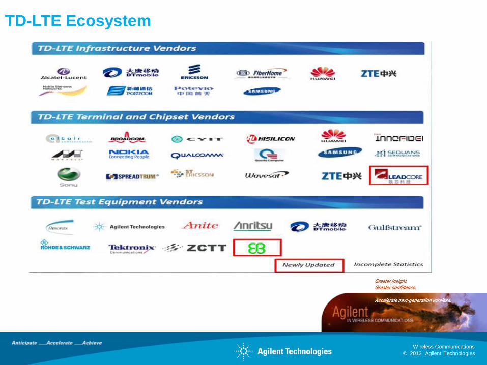
TD-LTE Ecosystem
© 2012 Agilent Technologies
Wireless Communications
Greater insight. Greater confidence.
Accelerate next-generation wireless.
Agenda Today
• TD-LTE background
• Worldwide rollouts for TD-LTE
• Key players for TD-LTE industry
• Technical differences between FDD and TDD
• Hot topics in TD-LTE
• Agilent solutions for TD-LTE and TD-LTE-A
• Wrap up
© 2012 Agilent Technologies
Wireless Communications
Greater insight. Greater confidence.
Accelerate next-generation wireless.
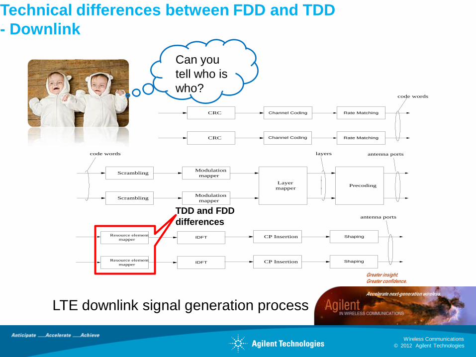
Technical differences between FDD and TDD
- Downlink
ScramblingModulation
mapper
Layer
mapperPrecoding
ScramblingModulation
mapper
layerscode words
CRC Channel Coding
CRC Channel Coding
Rate Matching
Rate Matching
code words
Resource element
mapperIDFT
Resource element
mapperIDFT
antenna ports
CP Insertion Shaping
CP Insertion Shaping
antenna ports
LTE downlink signal generation process
TDD and FDD
differences
Can you
tell who is
who?

© 2012 Agilent Technologies
Wireless Communications
Greater insight. Greater confidence.
Accelerate next-generation wireless.
Frame Structure for LTE FDD FDD: Uplink and downlink are transmitted
separately
#0 #2 #3 #18#1 ………. #19
One subframe
One slot, Tslot = 15360 x Ts = 0.5 ms
One radio frame, Tf = 307200 x Ts = 10 ms
Subframe 0 Subframe 1 Subframe 9
Frame Structure for TD-LTE
#0 #1 ……….
One subframe
One slot, Tslot = 15360 x Ts = 0.5 ms
One radio frame, Tf = 307200 x Ts = 10 ms
Subframe 0
DL subframe
Subframe 1
Special subframe
Subframe 9 DL/UL subframe
TDD: Uplink and downlink are transmitted in the same
spectrum
DwPTS GP UpPTS
#18 #19
Technical differences between FDD and TDD
- Downlink
© 2012 Agilent Technologies
Wireless Communications
Greater insight. Greater confidence.
Accelerate next-generation wireless.
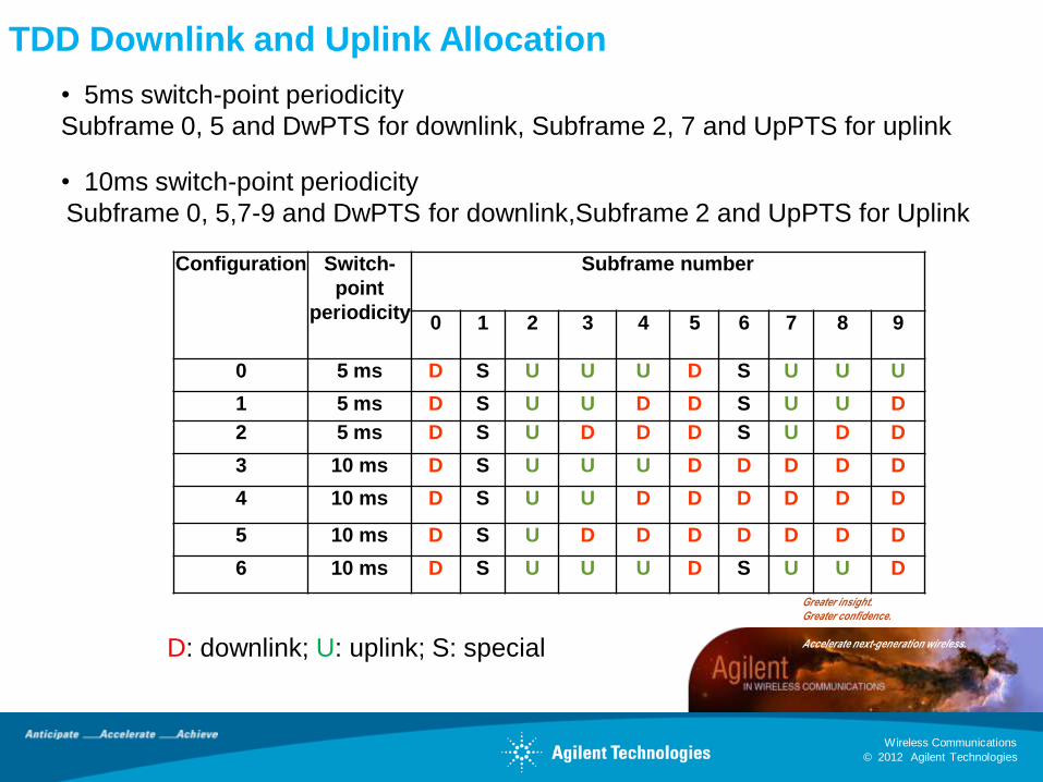
TDD Downlink and Uplink Allocation
Configuration Switch-
point
periodicity
Subframe number
0 1 2 3 4 5 6 7 8 9
0 5 ms D S U U U D S U U U
1 5 ms D S U U D D S U U D
2 5 ms D S U D D D S U D D
3 10 ms D S U U U D D D D D
4 10 ms D S U U D D D D D D
5 10 ms D S U D D D D D D D
6 10 ms D S U U U D S U U D
• 5ms switch-point periodicity
Subframe 0, 5 and DwPTS for downlink, Subframe 2, 7 and UpPTS for uplink
• 10ms switch-point periodicity
Subframe 0, 5,7-9 and DwPTS for downlink,Subframe 2 and UpPTS for Uplink
D: downlink; U: uplink; S: special
© 2012 Agilent Technologies
Wireless Communications
Greater insight. Greater confidence.
Accelerate next-generation wireless.
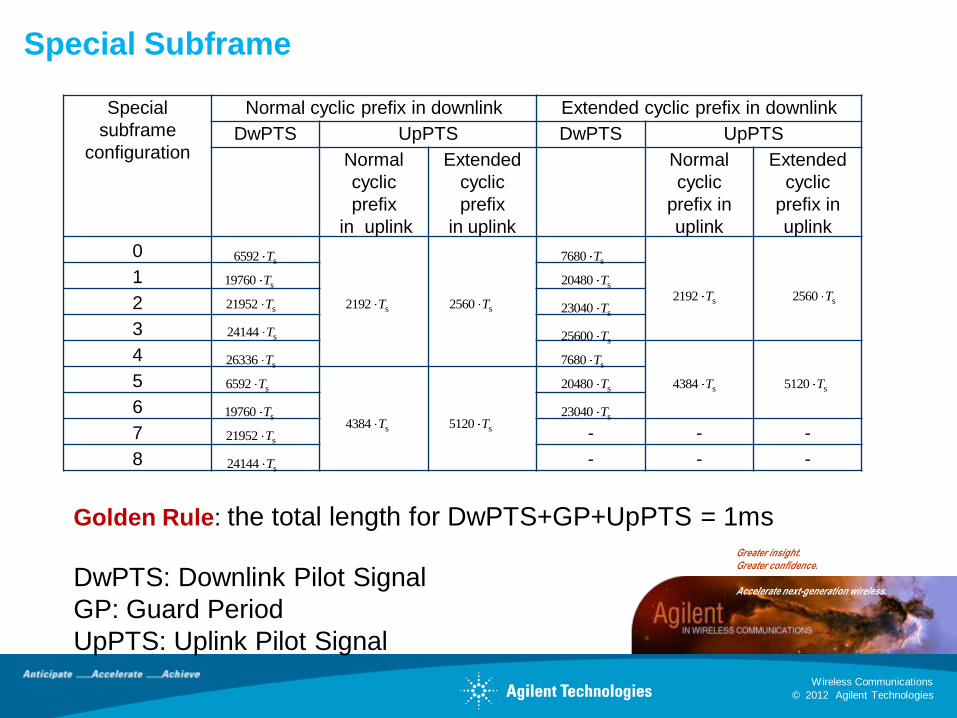
Special Subframe
Special
subframe
configuration
Normal cyclic prefix in downlink Extended cyclic prefix in downlink
DwPTS UpPTS DwPTS UpPTS
Normal
cyclic
prefix
in uplink
Extended
cyclic
prefix
in uplink
Normal
cyclic
prefix in
uplink
Extended
cyclic
prefix in
uplink
0
1
2
3
4
5
6
7 - - -
8 - - -
s6592 T
s2192 Ts2560 T
s7680 T
s2192 T s2560 T
s19760 T
s20480 T
s21952 T
s23040 T
s24144 Ts25600 T
s26336 T s7680 T
s4384 T s5120 Ts6592 T
s4384 T s5120 T
s20480 T
s19760 T
s23040 T
s21952 T
s24144 T
Golden Rule: the total length for DwPTS+GP+UpPTS = 1ms
DwPTS: Downlink Pilot Signal
GP: Guard Period
UpPTS: Uplink Pilot Signal
© 2012 Agilent Technologies
Wireless Communications
Greater insight. Greater confidence.
Accelerate next-generation wireless.
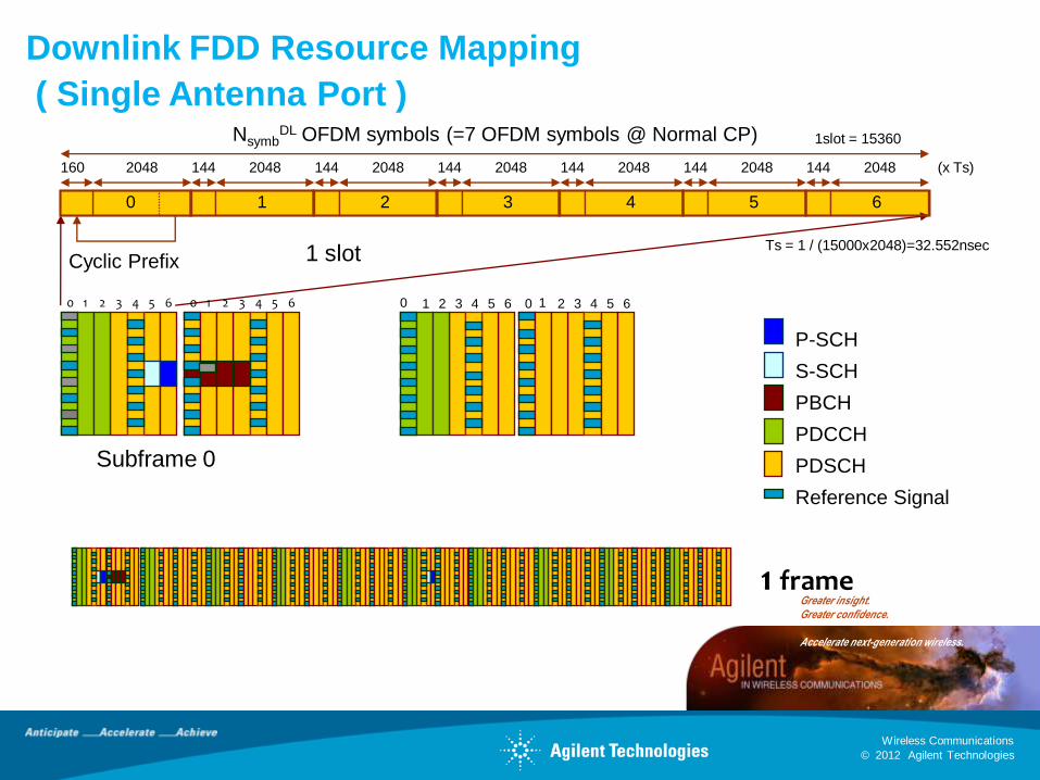
NsymbDL OFDM symbols (=7 OFDM symbols @ Normal CP)
Cyclic Prefix
160 2048 144 2048 144 2048 144 2048 144 2048 144 2048 144 2048 (x Ts)
1slot = 15360
0 1 2 3 4 5 6
Ts = 1 / (15000x2048)=32.552nsec1 slot
Subframe 0
P-SCH
S-SCH
PBCH
PDCCH
PDSCH
Reference Signal
Downlink FDD Resource Mapping
( Single Antenna Port )
10 2 3 4 5 6 10 2 3 4 5 6 10 2 3 4 5 6 10 2 3 4 5 6
1 frame
© 2012 Agilent Technologies
Wireless Communications
Greater insight. Greater confidence.
Accelerate next-generation wireless.
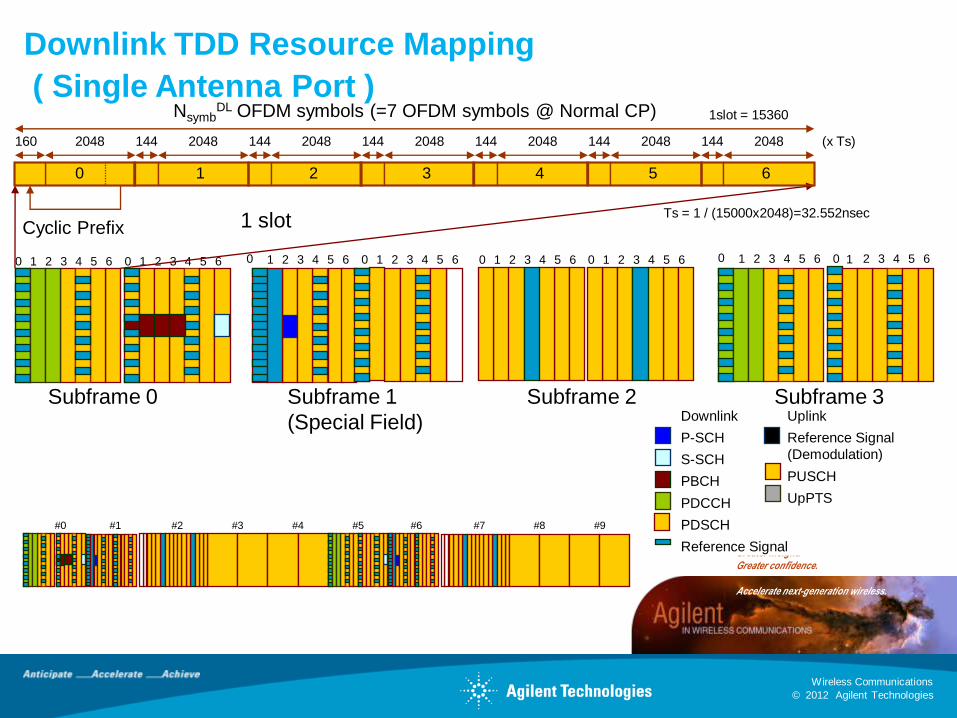
#0 #1 #8#2 #3 #4 #5 #6 #7 #9
10 2 3 4 5 6 10 2 3 4 5 6 10 2 3 4 5 6 10 2 3 4 5 6 10 2 3 4 5 6 10 2 3 4 5 6
NsymbDL OFDM symbols (=7 OFDM symbols @ Normal CP)
Cyclic Prefix
160 2048 144 2048 144 2048 144 2048 144 2048 144 2048 144 2048 (x Ts)
1slot = 15360
0 1 2 3 4 5 6
Ts = 1 / (15000x2048)=32.552nsec1 slot
Subframe 0Downlink
P-SCH
S-SCH
PBCH
PDCCH
PDSCH
Reference Signal
Uplink
Reference Signal
(Demodulation)
PUSCH
UpPTS
Downlink TDD Resource Mapping
( Single Antenna Port )
10 2 3 4 5 6 10 2 3 4 5 6
Subframe 1
(Special Field)
Subframe 2 Subframe 3
© 2012 Agilent Technologies
Wireless Communications
Greater insight. Greater confidence.
Accelerate next-generation wireless.
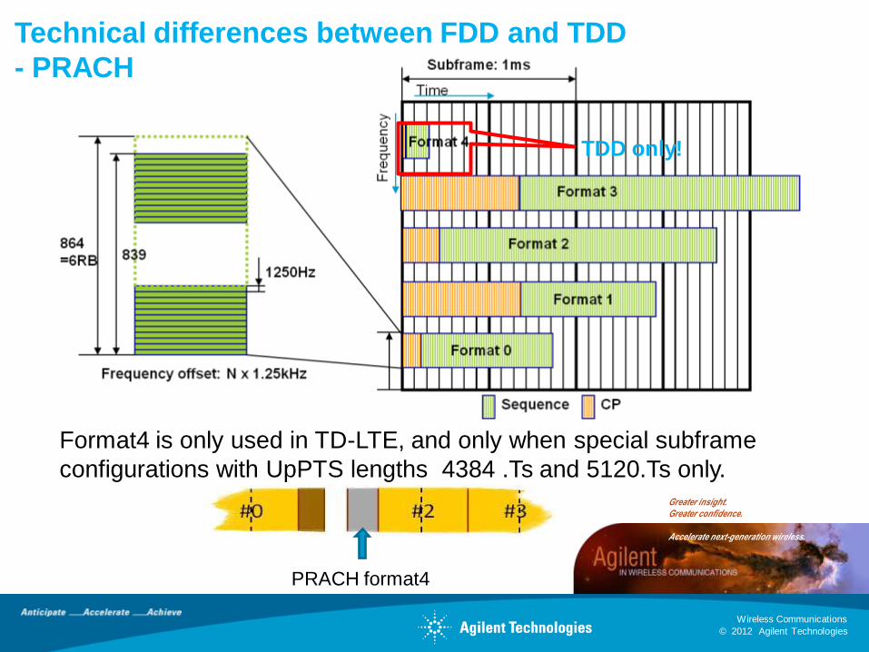
Format4 is only used in TD-LTE, and only when special subframe
configurations with UpPTS lengths 4384 .Ts and 5120.Ts only.
Technical differences between FDD and TDD
- PRACH
PRACH format4
TDD only!
© 2012 Agilent Technologies
Wireless Communications
Greater insight. Greater confidence.
Accelerate next-generation wireless.
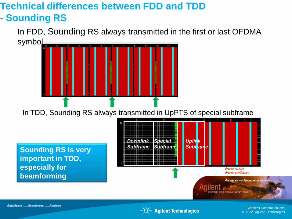
Technical differences between FDD and TDD
- Sounding RS
In FDD, Sounding RS always transmitted in the first or last OFDMA
symbol
In TDD, Sounding RS always transmitted in UpPTS of special subframe
Special
Subframe
Downlink
Subframe
Uplink
SubframeSounding RS is very
important in TDD,
especially for
beamforming
© 2012 Agilent Technologies
Wireless Communications
Greater insight. Greater confidence.
Accelerate next-generation wireless.
Agenda Today
• TD-LTE background
• Worldwide rollouts for TD-LTE
• Key players for TD-LTE industry
• Technical differences between FDD and TDD
• Hot topics in TD-LTE
• Agilent solutions for TD-LTE and TD-LTE-A
• Wrap up
© 2012 Agilent Technologies
Wireless Communications
Greater insight. Greater confidence.
Accelerate next-generation wireless.
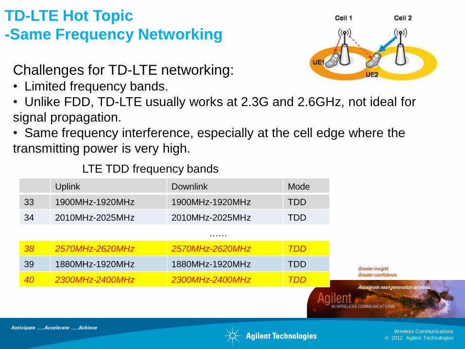
TD-LTE Hot Topic
-Same Frequency Networking
Challenges for TD-LTE networking:• Limited frequency bands.
• Unlike FDD, TD-LTE usually works at 2.3G and 2.6GHz, not ideal for
signal propagation.
• Same frequency interference, especially at the cell edge where the
transmitting power is very high.
Uplink Downlink Mode
33 1900MHz-1920MHz 1900MHz-1920MHz TDD
34 2010MHz-2025MHz 2010MHz-2025MHz TDD
……
38 2570MHz-2620MHz 2570MHz-2620MHz TDD
39 1880MHz-1920MHz 1880MHz-1920MHz TDD
40 2300MHz-2400MHz 2300MHz-2400MHz TDD
LTE TDD frequency bands
© 2012 Agilent Technologies
Wireless Communications
Greater insight. Greater confidence.
Accelerate next-generation wireless.
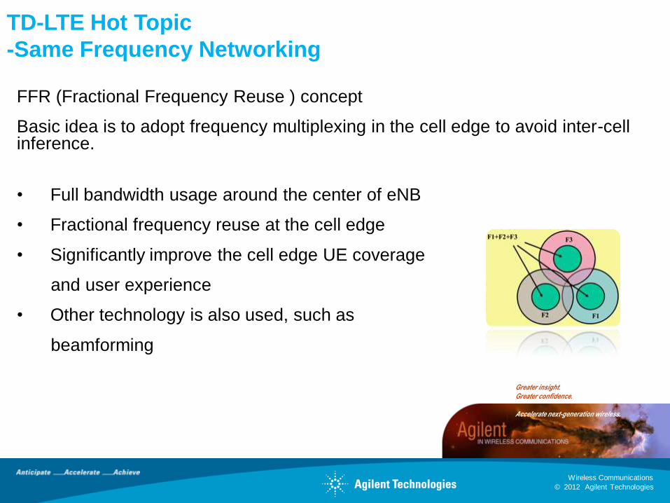
FFR (Fractional Frequency Reuse ) concept
Basic idea is to adopt frequency multiplexing in the cell edge to avoid inter-cell inference.
• Full bandwidth usage around the center of eNB
• Fractional frequency reuse at the cell edge
• Significantly improve the cell edge UE coverage
and user experience
• Other technology is also used, such as
beamforming
TD-LTE Hot Topic
-Same Frequency Networking
© 2012 Agilent Technologies
Wireless Communications
Greater insight. Greater confidence.
Accelerate next-generation wireless.
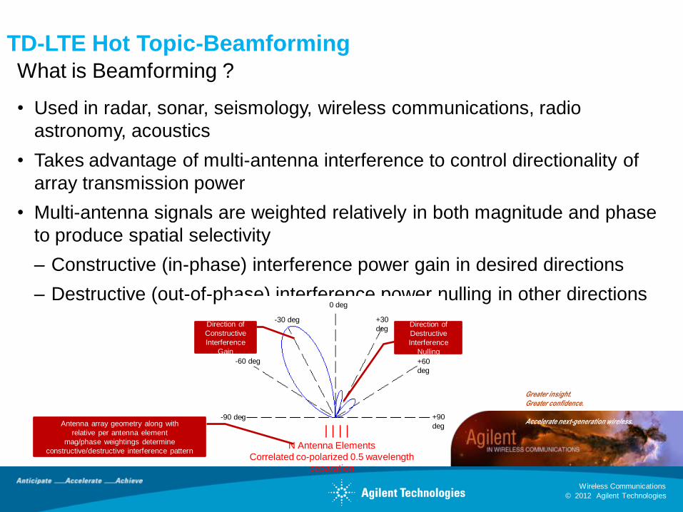
What is Beamforming ?
• Used in radar, sonar, seismology, wireless communications, radio
astronomy, acoustics
• Takes advantage of multi-antenna interference to control directionality of
array transmission power
• Multi-antenna signals are weighted relatively in both magnitude and phase
to produce spatial selectivity
– Constructive (in-phase) interference power gain in desired directions
– Destructive (out-of-phase) interference power nulling in other directions
TD-LTE Hot Topic-Beamforming
-90 deg
-60 deg
-30 deg
0 deg
+30
deg
+60
deg
+90
deg| | | |
N Antenna Elements
Correlated co-polarized 0.5 wavelength
separation
Direction of
Constructive
Interference
Gain
Direction of
Destructive
Interference
Nulling
Antenna array geometry along with
relative per antenna element
mag/phase weightings determine
constructive/destructive interference pattern
© 2012 Agilent Technologies
Wireless Communications
Greater insight. Greater confidence.
Accelerate next-generation wireless.
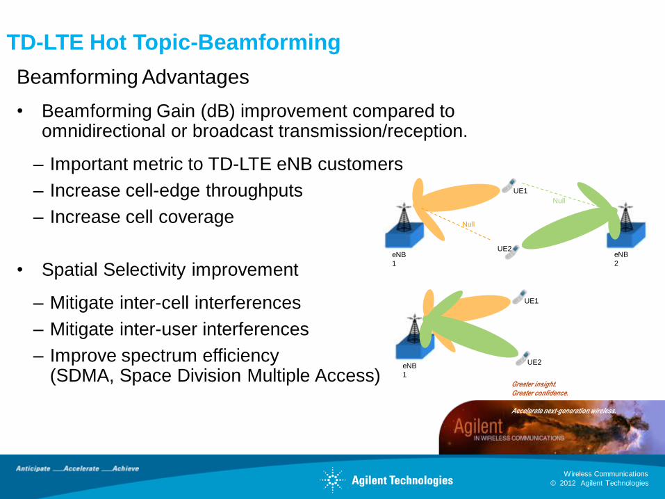
Beamforming Advantages
• Beamforming Gain (dB) improvement compared toomnidirectional or broadcast transmission/reception.
– Important metric to TD-LTE eNB customers
– Increase cell-edge throughputs
– Increase cell coverage
• Spatial Selectivity improvement
– Mitigate inter-cell interferences
– Mitigate inter-user interferences
– Improve spectrum efficiency (SDMA, Space Division Multiple Access)
eNB
1
eNB
2
UE1
UE2
eNB
1
UE1
UE2
Null
Null
TD-LTE Hot Topic-Beamforming
© 2012 Agilent Technologies
Wireless Communications
Greater insight. Greater confidence.
Accelerate next-generation wireless.
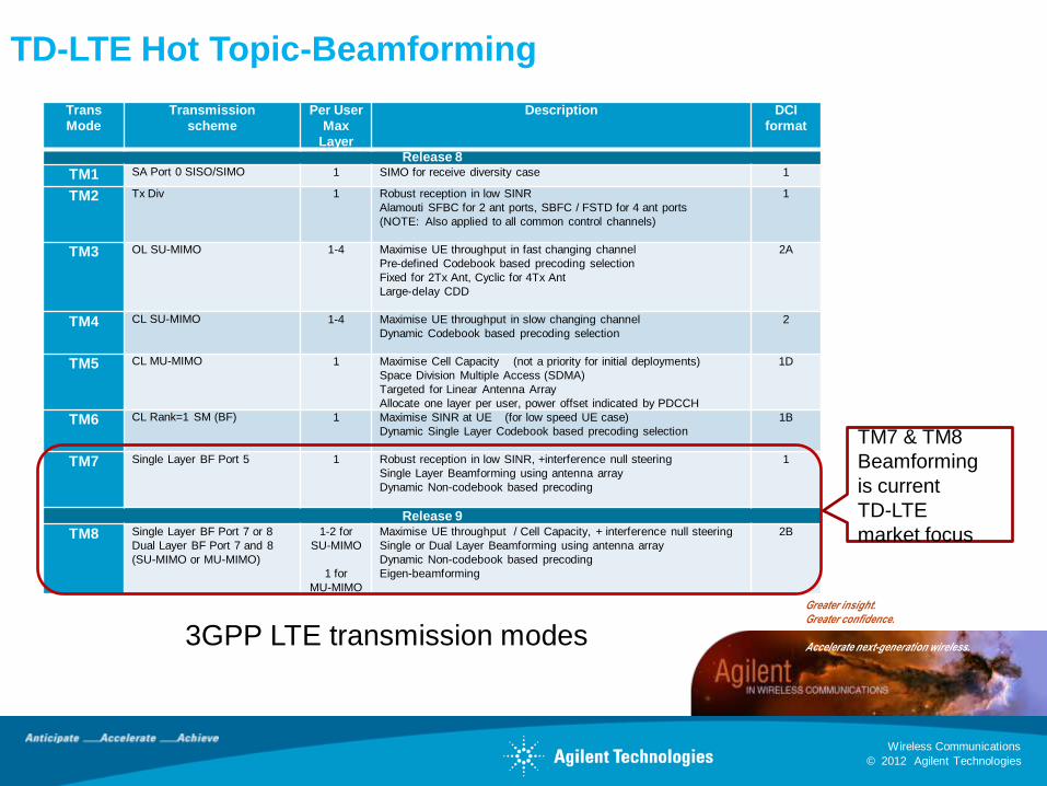
Trans
Mode
Transmission
scheme
Per User
Max
Layer
Description DCI
format
Release 8
TM1 SA Port 0 SISO/SIMO 1 SIMO for receive diversity case 1
TM2 Tx Div 1 Robust reception in low SINR
Alamouti SFBC for 2 ant ports, SBFC / FSTD for 4 ant ports
(NOTE: Also applied to all common control channels)
1
TM3 OL SU-MIMO 1-4 Maximise UE throughput in fast changing channel
Pre-defined Codebook based precoding selection
Fixed for 2Tx Ant, Cyclic for 4Tx Ant
Large-delay CDD
2A
TM4 CL SU-MIMO 1-4 Maximise UE throughput in slow changing channel
Dynamic Codebook based precoding selection
2
TM5 CL MU-MIMO 1 Maximise Cell Capacity (not a priority for initial deployments)
Space Division Multiple Access (SDMA)
Targeted for Linear Antenna Array
Allocate one layer per user, power offset indicated by PDCCH
1D
TM6 CL Rank=1 SM (BF) 1 Maximise SINR at UE (for low speed UE case)
Dynamic Single Layer Codebook based precoding selection
1B
TM7 Single Layer BF Port 5 1 Robust reception in low SINR, +interference null steering
Single Layer Beamforming using antenna array
Dynamic Non-codebook based precoding
1
Release 9
TM8 Single Layer BF Port 7 or 8
Dual Layer BF Port 7 and 8
(SU-MIMO or MU-MIMO)
1-2 for
SU-MIMO
1 for
MU-MIMO
Maximise UE throughput / Cell Capacity, + interference null steering
Single or Dual Layer Beamforming using antenna array
Dynamic Non-codebook based precoding
Eigen-beamforming
2B
TM7 & TM8
Beamforming
is current
TD-LTE
market focus
TD-LTE Hot Topic-Beamforming
3GPP LTE transmission modes
© 2012 Agilent Technologies
Wireless Communications
Greater insight. Greater confidence.
Accelerate next-generation wireless.
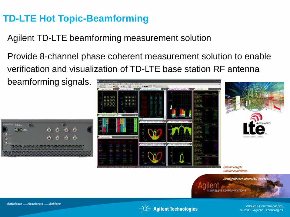
Agilent TD-LTE beamforming measurement solution
Provide 8-channel phase coherent measurement solution to enable
verification and visualization of TD-LTE base station RF antenna
beamforming signals.
TD-LTE Hot Topic-Beamforming
© 2012 Agilent Technologies
Wireless Communications
Greater insight. Greater confidence.
Accelerate next-generation wireless.
CAL
Coupler
eNB
RRHUE1
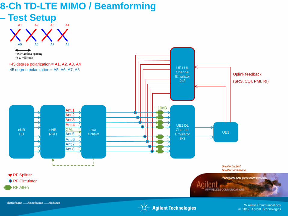
8-Ch TD-LTE MIMO / Beamforming
– Test Setup
eNB
BB
RF Splitter
Uplink feedback
(SRS, CQI, PMI, RI)
UE1 UL
Channel
Emulator
2x8
RF Circulator
RF Atten
UE1 DL
Channel
Emulator
8x2
~10dB
+45 degree polarization = A1, A2, A3, A4
-45 degree polarization = A5, A6, A7, A8
~0.5*lambda spacing
(e.g. ~65mm)
A1 A2 A3 A4
A5 A6 A7 A8
CAL
Ant 1Ant 2
Ant 3
Ant 4
Ant 5
Ant 6Ant 7
Ant 8
© 2012 Agilent Technologies
Wireless Communications
Greater insight. Greater confidence.
Accelerate next-generation wireless.
CAL
Coupler
eNB
RRH
UE1 DL
Channel
Emulator
8x2
UE1
Uplink feedback
(SRS, CQI, PMI, RI)
UE1 UL
Channel
Emulator
2x8
eNB
BB
RF Splitter
RF Circulator
RF Atten
~10dB
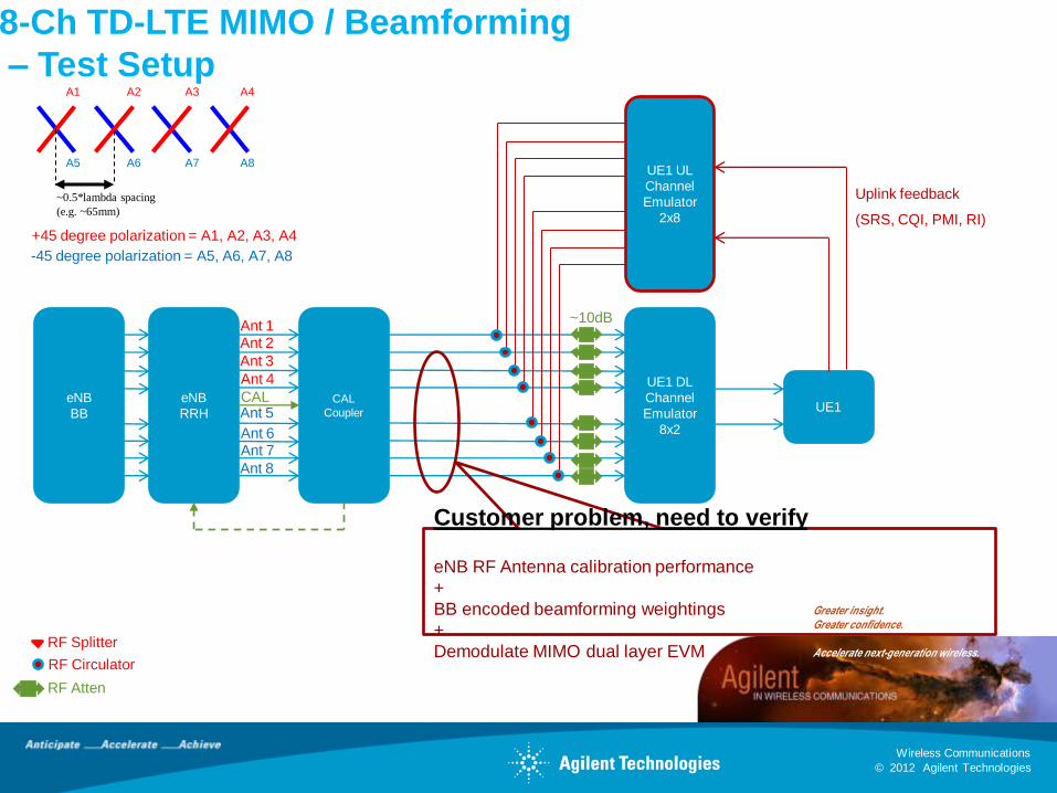
Customer problem, need to verify
eNB RF Antenna calibration performance
+
BB encoded beamforming weightings
+
Demodulate MIMO dual layer EVM
+45 degree polarization = A1, A2, A3, A4
-45 degree polarization = A5, A6, A7, A8
~0.5*lambda spacing
(e.g. ~65mm)
A1 A2 A3 A4
A5 A6 A7 A8
CAL
Ant 1Ant 2
Ant 3
Ant 4
Ant 5
Ant 6Ant 7
Ant 8
8-Ch TD-LTE MIMO / Beamforming
– Test Setup
© 2012 Agilent Technologies
Wireless Communications
Greater insight. Greater confidence.
Accelerate next-generation wireless.
CAL
Coupler
eNB
RRHUE1
eNB
BB
RF Splitter
Uplink feedback
(SRS, CQI, PMI, RI)
UE1 UL
Channel
Emulator
2x8
RF Circulator
RF Atten
UE1 DL
Channel
Emulator
8x2
~10dB
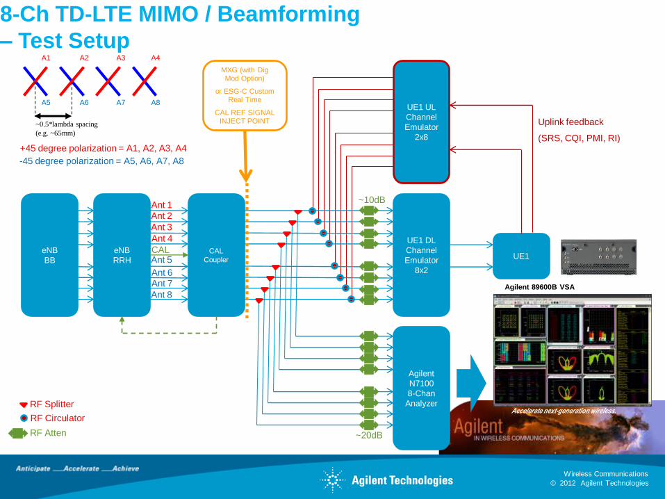
MXG (with Dig Mod Option)
or ESG-C Custom Real Time
CAL REF SIGNALINJECT POINT
Agilent
N7100
8-Chan
Analyzer
Agilent 89600B VSA
~20dB
+45 degree polarization = A1, A2, A3, A4
-45 degree polarization = A5, A6, A7, A8
~0.5*lambda spacing
(e.g. ~65mm)
A1 A2 A3 A4
A5 A6 A7 A8
CAL
Ant 1Ant 2
Ant 3
Ant 4
Ant 5
Ant 6Ant 7
Ant 8
8-Ch TD-LTE MIMO / Beamforming
– Test Setup
© 2012 Agilent Technologies
Wireless Communications
Greater insight. Greater confidence.
Accelerate next-generation wireless.
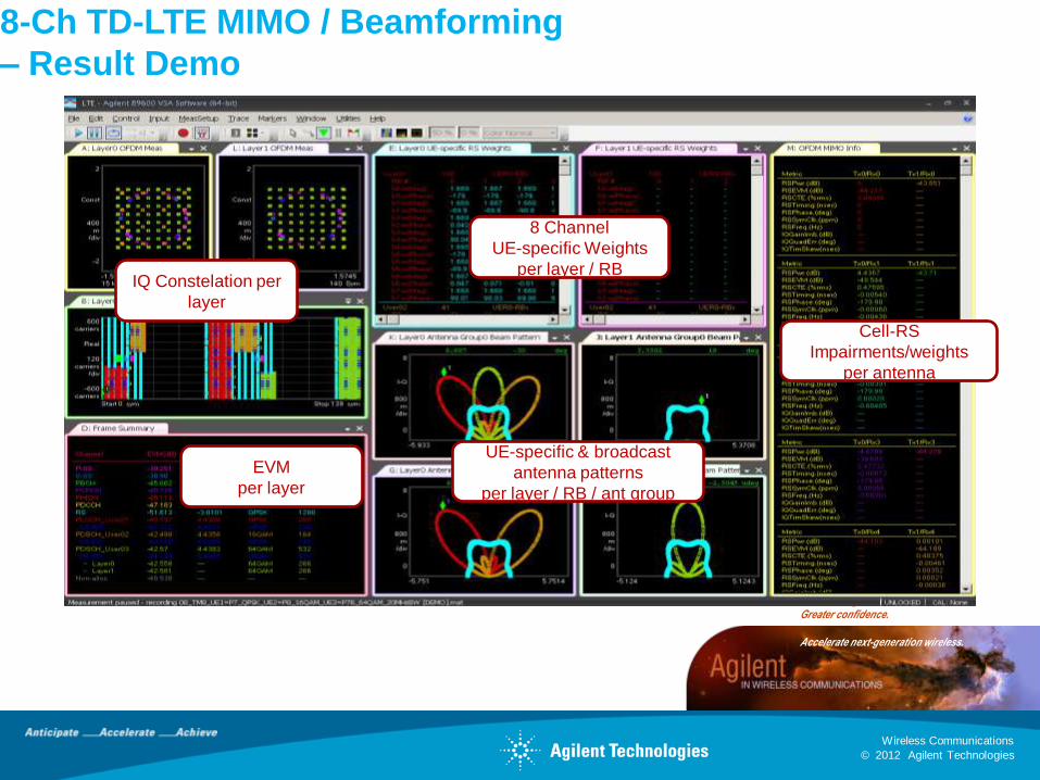
IQ Constelation per
layer
8 Channel
UE-specific Weights
per layer / RB
Cell-RS
Impairments/weights
per antenna
UE-specific & broadcast
antenna patterns
per layer / RB / ant group
EVM
per layer
8-Ch TD-LTE MIMO / Beamforming
– Result Demo
© 2012 Agilent Technologies
Wireless Communications
Greater insight. Greater confidence.
Accelerate next-generation wireless.
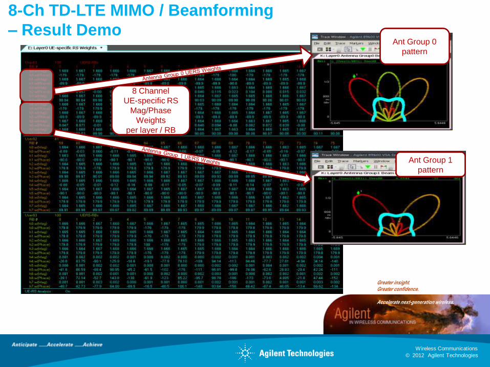
Ant Group 0
pattern
Ant Group 1
pattern
8 Channel
UE-specific RS
Mag/Phase
Weights
per layer / RB
8-Ch TD-LTE MIMO / Beamforming
– Result Demo
© 2012 Agilent Technologies
Wireless Communications
Greater insight. Greater confidence.
Accelerate next-generation wireless.
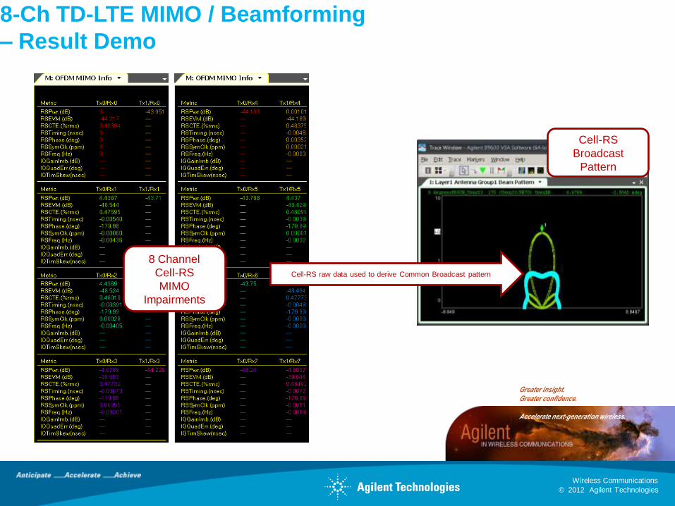
Cell-RS raw data used to derive Common Broadcast pattern
Cell-RS
Broadcast
Pattern
8 Channel
Cell-RS
MIMO
Impairments
8-Ch TD-LTE MIMO / Beamforming
– Result Demo
© 2012 Agilent Technologies
Wireless Communications
Greater insight. Greater confidence.
Accelerate next-generation wireless.
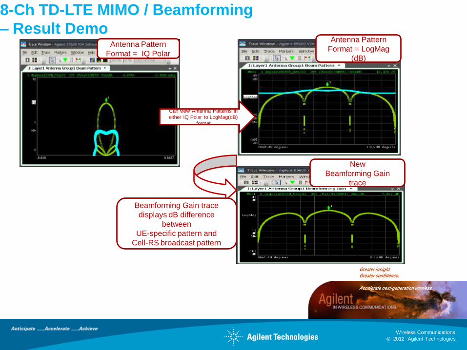
Beamforming Gain trace
displays dB difference
between
UE-specific pattern and
Cell-RS broadcast pattern
New
Beamforming Gain
trace
Antenna Pattern
Format = IQ Polar
Can view Antenna Patterns in
either IQ Polar to LogMag(dB)
format
Antenna Pattern
Format = LogMag
(dB)
8-Ch TD-LTE MIMO / Beamforming
– Result Demo
© 2012 Agilent Technologies
Wireless Communications
Greater insight. Greater confidence.
Accelerate next-generation wireless.
Agenda Today
• TD-LTE background
• Worldwide rollouts for TD-LTE
• Key players for TD-LTE industry
• Technical differences between FDD and TDD
• Hot topics in TD-LTE
• Agilent solutions for TD-LTE and TD-LTE-A
• Wrap up
© 2012 Agilent Technologies
Wireless Communications
Greater insight. Greater confidence.
Accelerate next-generation wireless.
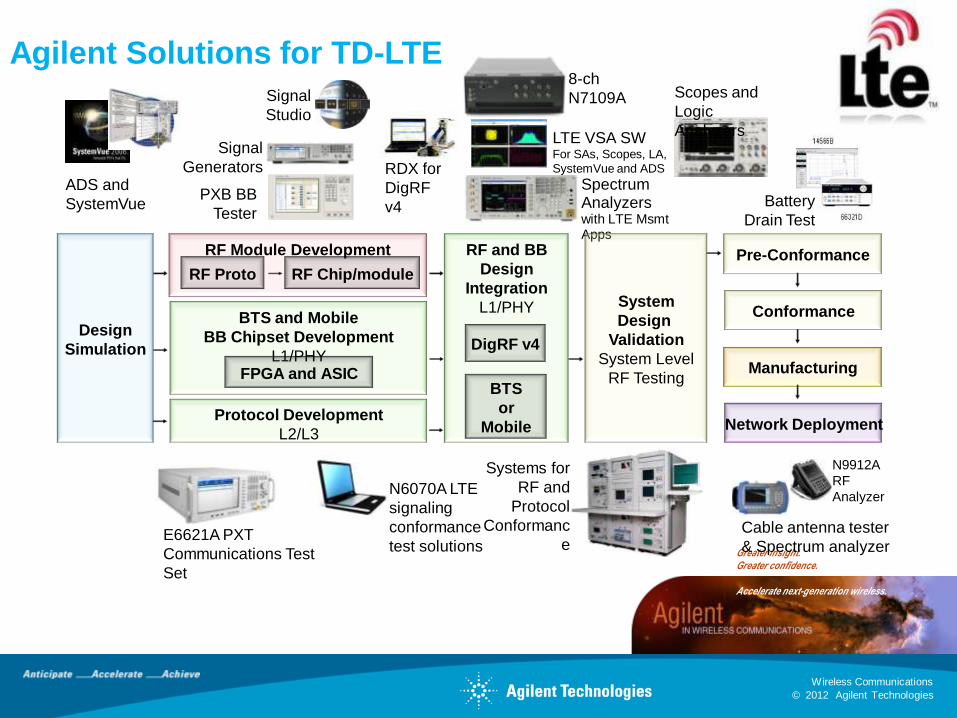
Agilent Solutions for TD-LTE
ADS and
SystemVue
LTE VSA SWFor SAs, Scopes, LA,
SystemVue and ADS
Spectrum Analyzerswith LTE MsmtApps
Signal
Studio
Signal
Generators
PXB BB
Tester
N9912A
RF
Analyzer
RDX for
DigRF
v4
E6621A PXT
Communications Test
Set
N6070A LTE
signaling
conformance
test solutions
Cable antenna tester
& Spectrum analyzer
Battery
Drain Test
Systems for
RF and
Protocol
Conformanc
e
Scopes and
Logic
Analyzers
RF Module Development
RF Proto RF Chip/module
Design
Simulation
BTS and Mobile
BB Chipset Development
L1/PHYFPGA and ASIC
Conformance
RF and BB
Design
Integration
L1/PHY System
Design
Validation
System Level
RF TestingBTS
or
MobileProtocol Development
L2/L3
DigRF v4
Pre-Conformance
Network Deployment
Manufacturing
8-ch
N7109A
© 2012 Agilent Technologies
Wireless Communications
Greater insight. Greater confidence.
Accelerate next-generation wireless.
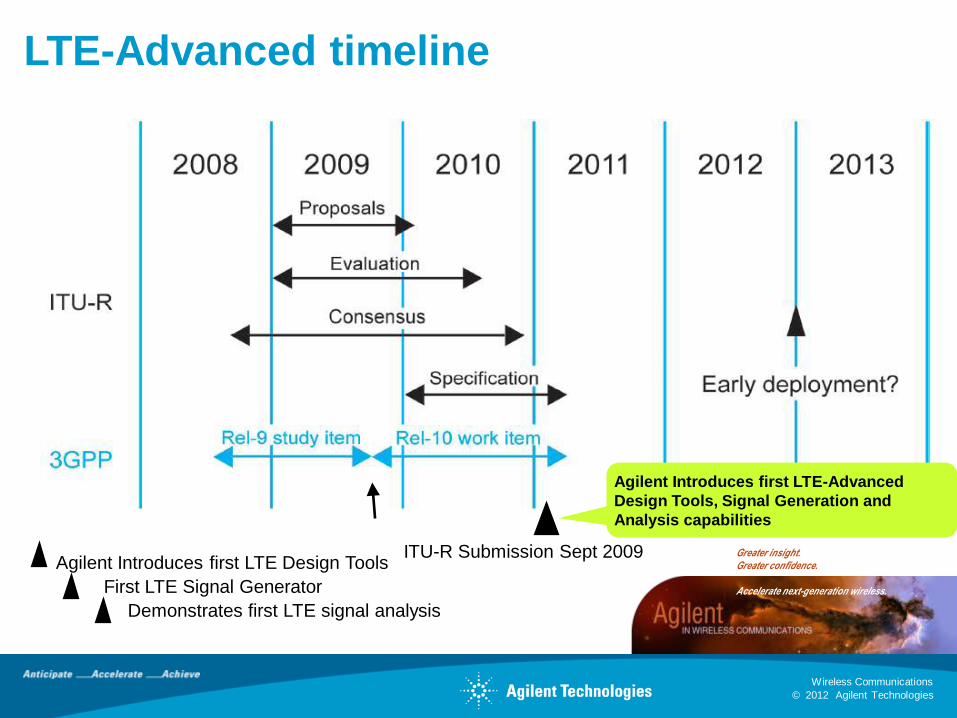
LTE-Advanced timeline
ITU-R Submission Sept 2009Agilent Introduces first LTE Design Tools
First LTE Signal Generator
Demonstrates first LTE signal analysis
Agilent Introduces first LTE-Advanced
Design Tools, Signal Generation and
Analysis capabilities

© 2012 Agilent Technologies
Wireless Communications
Greater insight. Greater confidence.
Accelerate next-generation wireless.
Agilent Solutions for TD-LTE-Advanced
ADS
and
SystemVue
LTE VSA SWFor SAs, Scopes, LA,
SystemVue and ADS
Spectrum Analyzers
Signal
Studio
Signal
Generators
PXB BB
Tester
RF Module Development
RF Proto RF Chip/module
Design
Simulation
BTS and Mobile
BB Chipset Development
L1/PHY
FPGA and ASIC
Conformance
RF and BB
Design
Integration
L1/PHY System
Design
Validation
System Level
RF TestingBTS
or
MobileProtocol Development
L2/L3
DigRF v4
Pre-Conformance
Network Deployment
Manufacturing
Greater insight. Greater confidence.
Now in LTE-Advanced
8-ch
N7109A
© 2012 Agilent Technologies
Wireless Communications
Greater insight. Greater confidence.
Accelerate next-generation wireless.
Thanks!


![EX flex Scanning Receiver - livingston-products.com · The SeeGull EXflex supports LTE FDD, TD-LTE, UMTS [WCDMA/HSPA(+)], TD-SCDMA, GSM, CDMA, EV-DO operating bands currently deployed](https://img.pdfslide.us/doc/110x75/5b5d3f3c7f8b9ad2198df29a/ex-flex-scanning-receiver-livingston-the-seegull-exflex-supports-lte-fdd.jpg)