Embed Size (px)
Citation preview

Jim O’FlahertyAutodesk Licensing & Support Manager – MHS, Inc.
Radu StancescuAutodesk Inventor Administrator, Benson Industries
It’s STILL all in the Details – Tips & Tricks for Detailing in Inventor

About the speakerJim O’Flaherty
• Began career in 1980 as a Draftsman (on the board)
• Worked in the industries of:
• Avionics
• Autodesk Reseller
• Automotive
• Consumer goods
• Industrial Machinery
• Nuclear Waste removal
• Power Generation
• Parcel Conveyors
• Autodesk Inventor since Release 3
• 1st Commercial implementation of Autodesk Vault Workgroup
• Autodesk Expert Elite since 2014
• Autodesk Inventor Certified Professional/Instructor
• Autodesk University Speaker 2015 thru 2020
• Autodesk University Speaker Mentor 2017 thru 2020
• Known as The Angry Elf & Angry Elf’s Alter Ego on Discussion Groups
Angry Elf Angry Elf’s Alter Ego

About the speakerJim O’Flaherty – Personal Life
Proud father to my all-too-great kids (2 & 4 legged)
Connoisseur of fine whiskey and movies
Guitar player (more owner these days)
And a slight fan of a little known band from England

About the speakerJim O’Flaherty – Professional Life
Material Handling Systems, Inc.

About the speaker
Radu Stancescu - Work
Radu has over 20 years in the mechanical design usingAutodesk software and several years in implementingERP and Data Management products; currently he’sworking in the IT division at Benson Industries, apremier custom curtainwall and external claddingsubcontractor in the USA and Asia. Radu is an AutodeskInventor Certified Professional, Implementation CertifiedExpert and an Autodesk Certified Instructor since 2007.He’s also been a speaker at Autodesk Accelerate 2019.

About the speaker
Radu Stancescu – Hobbies
Family
Ultramarathon Runner
High Altitude Mountaineering Climber (Hiker)
Professional Soccer Referee (past)
Chess
Food, Drinks
Pokemon Go

About the speaker
Radu Stancescu – Benson Industries
Marina Bay
The New York Times
Sales Force Tower
One World Trade Center

Preface – The Legal Details of the Details

Preface – The Legalities of a Mechanical Drawing
Legally speaking drawings are in fact legal documents.
They communicate all the needed information about what is to be created for the customer.
If the product is produced incorrectly, liability can be assigned to the responsible party based on the drawing and whether the product was created per the drawing specification or not.
If those specifications are found to be wrong, liability falls squarely on those who signed the approvals for the drawing, i.e. Engineer, Director of Engineering, QA, etc.

Inventor Detail Drawing Environment & Options

Section #1 - Views
Manipulating Views
Once you’ve placed a view, they can be manipulated in a number of ways. Some of the more common are:
• Aligning Horizontally or Vertically
• Rotating normal to an edge, to an absolute angle or Relative Angle
• Scale
• Name

https://youtu.be/xJDXQsnJv8Y

Section #1 - Views
Section Views
Section Views are one of the more common types of views you’ll use in detailing your parts and assemblies.

https://youtu.be/_Kq9_Mqn31s

Section #1 - Views
Break Out Views
Break Out Views are used to display the areas or components that may be hidden by other components of the assembly model. Break Out Views are used to display the areas or components that may be hidden by other components of the assembly model.

https://youtu.be/XEtBufDT2NE

Section #1 - Views
Detail Views
Detail Views are used to enlarge an area of a parent view in order to display the details more clearly.

https://youtu.be/BUrPjwgl-O4

Standard and Custom Symbols

Section #2 – Standard Symbols
Standard Symbols are predefined annotations such as surface texture, features control frame, welding ordatum identifier. You can copy existing symbols and paste them in your drawings as new symbols toquickly and easily create new symbols. The active style determines the symbol appearance; for furtherdetails see the Style and Standard Editor.
You can copy existing symbols and paste them in your drawings to quickly and easily create new symbols.

Section #2 – Custom Symbols
Local sketch symbols are stored in the Drawing Resources Sketch Symbols folder in the browser.Symbols created in the current drawing can be saved locally or to an external symbol library. Symbolscreated in a template file are available locally in all drawings using the template. Symbols added to andstored in a sketch symbol library can be accessed by multiple users and computers.

Section #2 – Custom Symbols
You can save all your sketch symbols to a sketch symbol library. If no library exists, select the Create a NewLibrary icon to create a new external library. Select the folder icon to create a subfolder within the selected libraryif desired.
Note: Sketch Symbol Library location is saved by default to C:Users\Public\Documents\Autodesk\Inventor2020\Design Data\Symbol Library. You can add, delete, or rename libraries at this location.
Two sketch symbols cannot be saved to the symbol library with the same name; actually, a library is a drawing.
A sketch symbol can contain geometry, text, iProperties, prompted text and imported images.
All of these are going to be demonstrated now
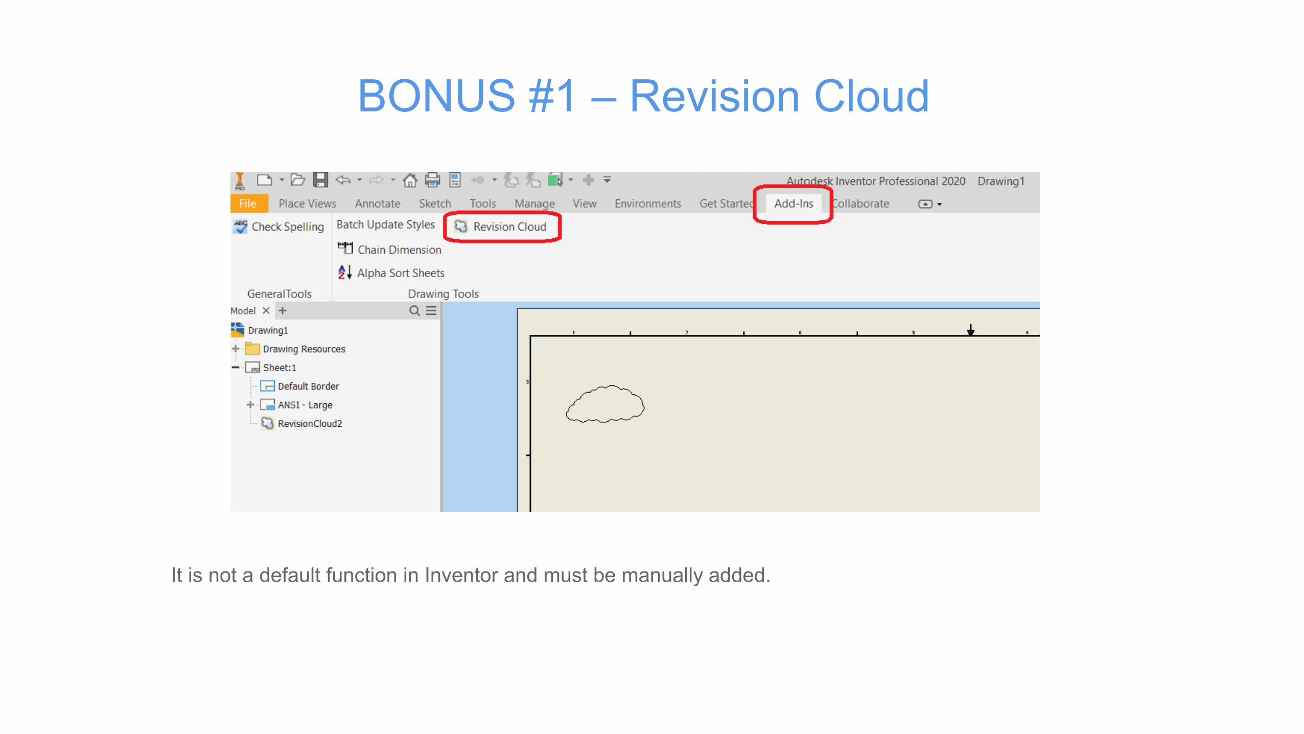
BONUS #1 – Revision Cloud
It is not a default function in Inventor and must be manually added.

BONUS #2 – Symbol Mask

Dimensioning Tips & Tricks

Section #3 – Dimensioning Tips & Tricks
Intersection Dimensions
Intersection Dimensions require a few extra steps and specific order of those steps to function correctly or to give you the dimension you desire. A little finesse and you’re good to go.
Let’s take a look at this dimension type.

https://youtu.be/_ULAN7NHcok

Section #3 – Dimensioning Tips & Tricks
Tangent Dimensions
Note: this is for those using per-2020 release
Even more so than Intersection Dimensions, Tangent Dimensions require a level of finesse…that and a keen eye.
Let’s take a look as to why that is.

https://youtu.be/w4tuLkSrYAc
Section #3 – Dimensioning Tips & Tricks
Model Dimensions
Using Model Dimensions offer numerous benefits, from eliminating the need to manually insert the dimensions on the detail sheet to having the ability to edit the model from the detail sheet, avoiding opening the model file or flipping back and forth between the two files.
Let’s demonstrate…

https://youtu.be/ksOZe6Qx9Bw

Section #3 – Dimensioning Tips & Tricks
Ordinate Dimensions in Detail Views
Creating an Ordinate dimension or a set of, in a Detail View, has always been a bit of a head scratcher. But once you know how, you’ll be able to impress your friends at a party.
Let’s demonstrate…

https://youtu.be/i28tfrM3yRo

Modeling for Drawings –Design Views and Level of Details
Section #4 – View Representations
View Representations control component visibility and transparency, sketch and work feature visibility,component selection status (enabled or not enabled), appearance and style characteristics applied in theassembly, zoom magnification, viewing angle and others. Turning off the visibility of components doesnot remove them from your system's RAM therefore View Representations are not used to managememory.
Note: When a component is set to Transparent in the assembly, transparency is carried over inassociative drawing views. Drawing view transparency overrides are disabled in these associative views.To manage component transparency in the drawing view you must turn off the view associativity.

Section #4 – Practice 1
A. Opening a new assembly B. Opening an existing assembly

Section #4 – View Representations
They can be used as a filter in the drawing's part list.
Lock the View representation option

Section #4 – Practice 2

Section #4 – LOD Representations
Level of Detail Representations improve capacity and performance. They suppress unneededcomponents or replace many parts with a single part representation to reduce memory consumption andto simplify the modeling environment. Save the representation with a name and activate it for modelingtasks or select it for creating drawings.
Level of Detail Representations control only suppression states of components and are used to managememory by not loading the parts into RAM. They cannot be used to filter the drawing's part list.
Use the capacity meter to manage memory consumption. To improve performance when working on alarge assembly, use the capacity meter to determine the current state of memory consumption. When youwant to reduce memory consumption, determine if you can suppress some components and create a newLevel of Detail representation or use a Substitute Level of Detail to reduce memory consumption evenfurther.

Section #4 – Practice 3

Questions?

Autodesk and the Autodesk logo are registered trademarks or trademarks of Autodesk, Inc., and/or its subsidiaries and/or affiliates in the USA and/or other countries. All other brand names, product names, or trademarks belong to their respective holders. Autodesk reserves the right to alter product and services offerings, and specifications and pricing at any time without notice, and is not responsible for typographical or graphical errors that may appear in this document.© 2020 Autodesk. All rights reserved.