Embed Size (px)
Citation preview
Itron (Sprague) Meter Installation
TDC-0823-009 100G DLS Gas ERT Module Installation Guide, Direct Mount 43
Proprietary and Confidential
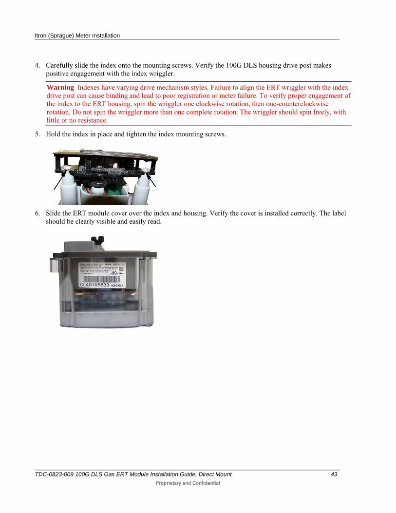
4. Carefully slide the index onto the mounting screws. Verify the 100G DLS housing drive post makes positive engagement with the index wriggler.
Warning Indexes have varying drive mechanism styles. Failure to align the ERT wriggler with the index drive post can cause binding and lead to poor registration or meter failure. To verify proper engagement of the index to the ERT housing, spin the wriggler one clockwise rotation, then one-counterclockwise rotation. Do not spin the wriggler more than one complete rotation. The wriggler should spin freely, with little or no resistance.
5. Hold the index in place and tighten the index mounting screws.
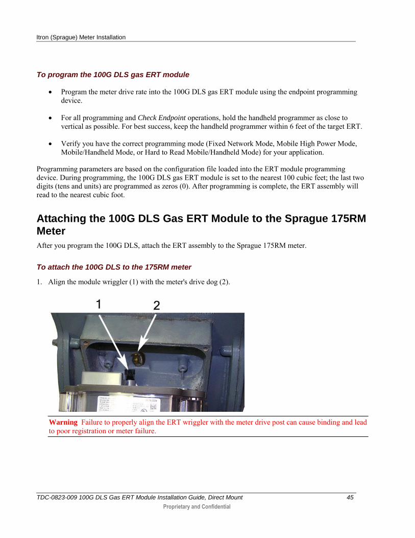
6. Slide the ERT module cover over the index and housing. Verify the cover is installed correctly. The label
should be clearly visible and easily read.

Itron (Sprague) Meter Installation
TDC-0823-009 100G DLS Gas ERT Module Installation Guide, Direct Mount 44
Proprietary and Confidential
Programming the 100G DLS Gas ERT Module Assembly
Program the 100G DLSs using:
An FC200SR handheld computer with Field Deployment Manager (FDM) software version 1.1 or higher or
A FC300 with SRead handheld computer with Field Deployment Manager (FDM) software version 1.1 or higher or
A 900MHz Belt Clip Radio with Field Deployment Manager (FDM) software version 1.1 or higher and a customer-supplied laptop. The Belt Clip Radio connects to the user-supplied laptop using a USB cable or Bluetooth.
See the Field Deployment Manager Endpoint Tools Mobile Application Guide (TDC-0934) for more complete programming information.
FC200SR FC300 with SRead 900MHz Belt Clip Radio
Caution You must program the 100G DLS gas ERT module before use.
The ERT is programmed based on the meter's drive rate. Take note of the index drive rate shown on a lower dial on the index. Elster American meter index drive rates are either 1-cubic foot, 2-cubic feet or 0.05 cubic meters (not shown below).
Itron (Sprague) Meter Installation
TDC-0823-009 100G DLS Gas ERT Module Installation Guide, Direct Mount 45
Proprietary and Confidential
To program the 100G DLS gas ERT module
Program the meter drive rate into the 100G DLS gas ERT module using the endpoint programming device.
For all programming and Check Endpoint operations, hold the handheld programmer as close to vertical as possible. For best success, keep the handheld programmer within 6 feet of the target ERT.
Verify you have the correct programming mode (Fixed Network Mode, Mobile High Power Mode, Mobile/Handheld Mode, or Hard to Read Mobile/Handheld Mode) for your application.
Programming parameters are based on the configuration file loaded into the ERT module programming device. During programming, the 100G DLS gas ERT module is set to the nearest 100 cubic feet; the last two digits (tens and units) are programmed as zeros (0). After programming is complete, the ERT assembly will read to the nearest cubic foot.
Attaching the 100G DLS Gas ERT Module to the Sprague 175RM Meter
After you program the 100G DLS, attach the ERT assembly to the Sprague 175RM meter.
To attach the 100G DLS to the 175RM meter
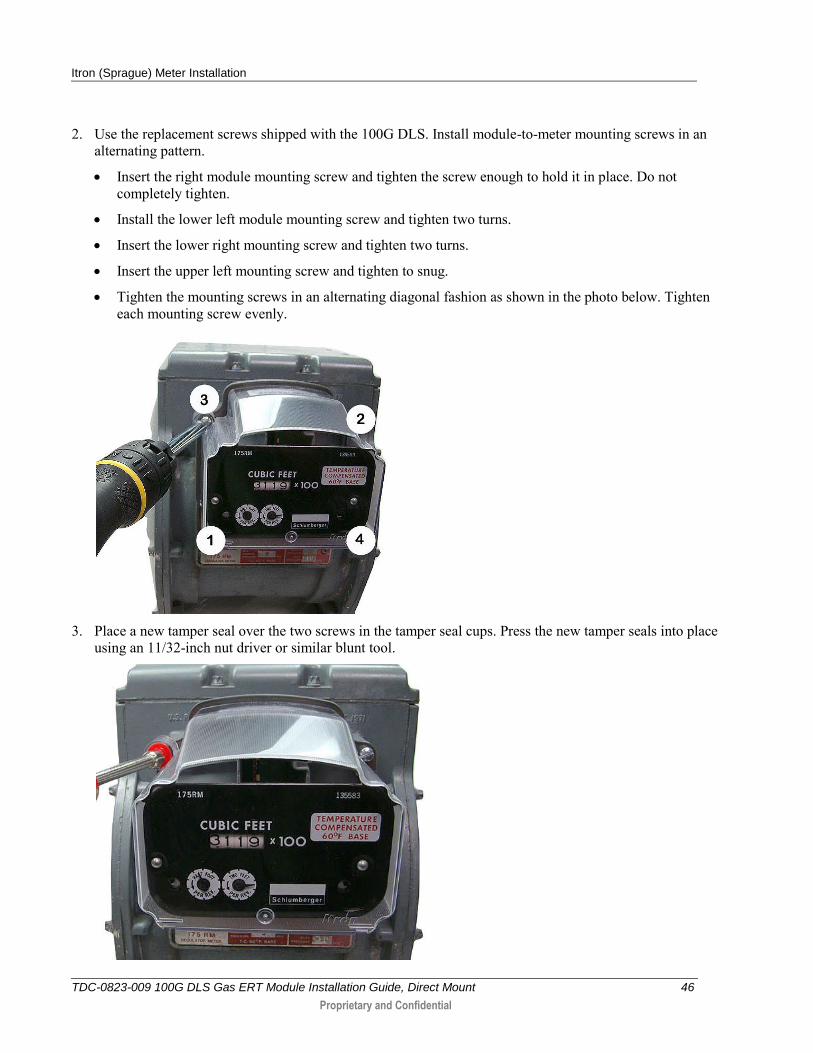
1. Align the module wriggler (1) with the meter's drive dog (2).
Warning Failure to properly align the ERT wriggler with the meter drive post can cause binding and lead to poor registration or meter failure.
Itron (Sprague) Meter Installation
TDC-0823-009 100G DLS Gas ERT Module Installation Guide, Direct Mount 46
Proprietary and Confidential
2. Use the replacement screws shipped with the 100G DLS. Install module-to-meter mounting screws in an alternating pattern.
Insert the right module mounting screw and tighten the screw enough to hold it in place. Do not completely tighten.
Install the lower left module mounting screw and tighten two turns.
Insert the lower right mounting screw and tighten two turns.
Insert the upper left mounting screw and tighten to snug.
Tighten the mounting screws in an alternating diagonal fashion as shown in the photo below. Tighten each mounting screw evenly.
3. Place a new tamper seal over the two screws in the tamper seal cups. Press the new tamper seals into place
using an 11/32-inch nut driver or similar blunt tool.
Itron (Sprague) Meter Installation
TDC-0823-009 100G DLS Gas ERT Module Installation Guide, Direct Mount 47
Proprietary and Confidential
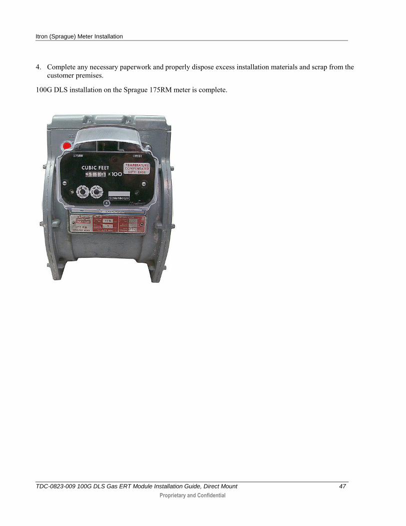
4. Complete any necessary paperwork and properly dispose excess installation materials and scrap from the customer premises.
100G DLS installation on the Sprague 175RM meter is complete.
TDC-0823-009 100G DLS Gas ERT Module Installation Guide, Direct Mount 48
Proprietary and Confidential
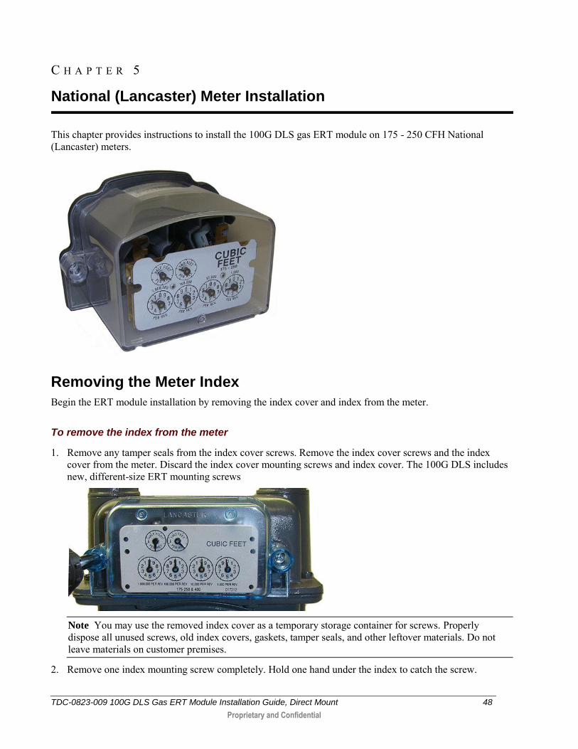
This chapter provides instructions to install the 100G DLS gas ERT module on 175 - 250 CFH National (Lancaster) meters.
Removing the Meter Index
Begin the ERT module installation by removing the index cover and index from the meter.
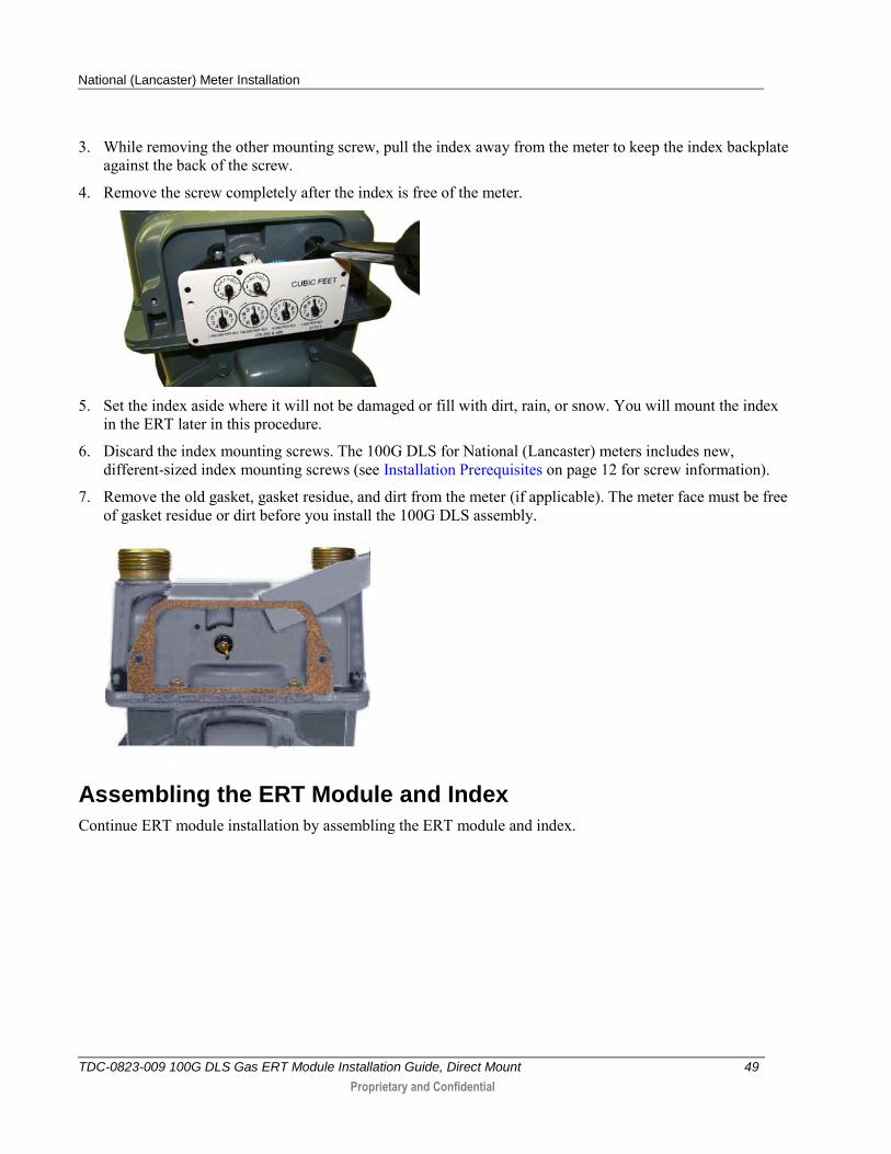
To remove the index from the meter
1. Remove any tamper seals from the index cover screws. Remove the index cover screws and the index cover from the meter. Discard the index cover mounting screws and index cover. The 100G DLS includes new, different-size ERT mounting screws
Note You may use the removed index cover as a temporary storage container for screws. Properly dispose all unused screws, old index covers, gaskets, tamper seals, and other leftover materials. Do not leave materials on customer premises.
2. Remove one index mounting screw completely. Hold one hand under the index to catch the screw.
C H A P T E R 5
National (Lancaster) Meter Installation
National (Lancaster) Meter Installation
TDC-0823-009 100G DLS Gas ERT Module Installation Guide, Direct Mount 49
Proprietary and Confidential
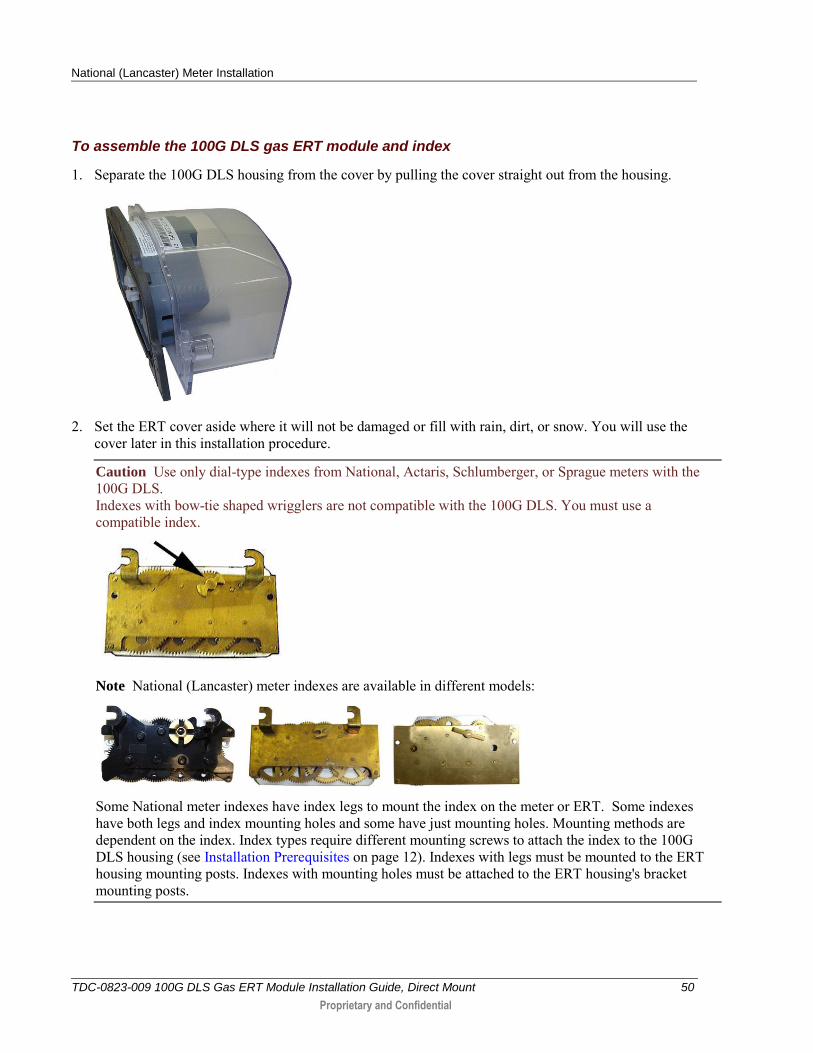
3. While removing the other mounting screw, pull the index away from the meter to keep the index backplate against the back of the screw.
4. Remove the screw completely after the index is free of the meter.
5. Set the index aside where it will not be damaged or fill with dirt, rain, or snow. You will mount the index
in the ERT later in this procedure.
6. Discard the index mounting screws. The 100G DLS for National (Lancaster) meters includes new, different-sized index mounting screws (see Installation Prerequisites on page 12 for screw information).
7. Remove the old gasket, gasket residue, and dirt from the meter (if applicable). The meter face must be free of gasket residue or dirt before you install the 100G DLS assembly.
Assembling the ERT Module and Index
Continue ERT module installation by assembling the ERT module and index.
National (Lancaster) Meter Installation
TDC-0823-009 100G DLS Gas ERT Module Installation Guide, Direct Mount 50
Proprietary and Confidential
To assemble the 100G DLS gas ERT module and index
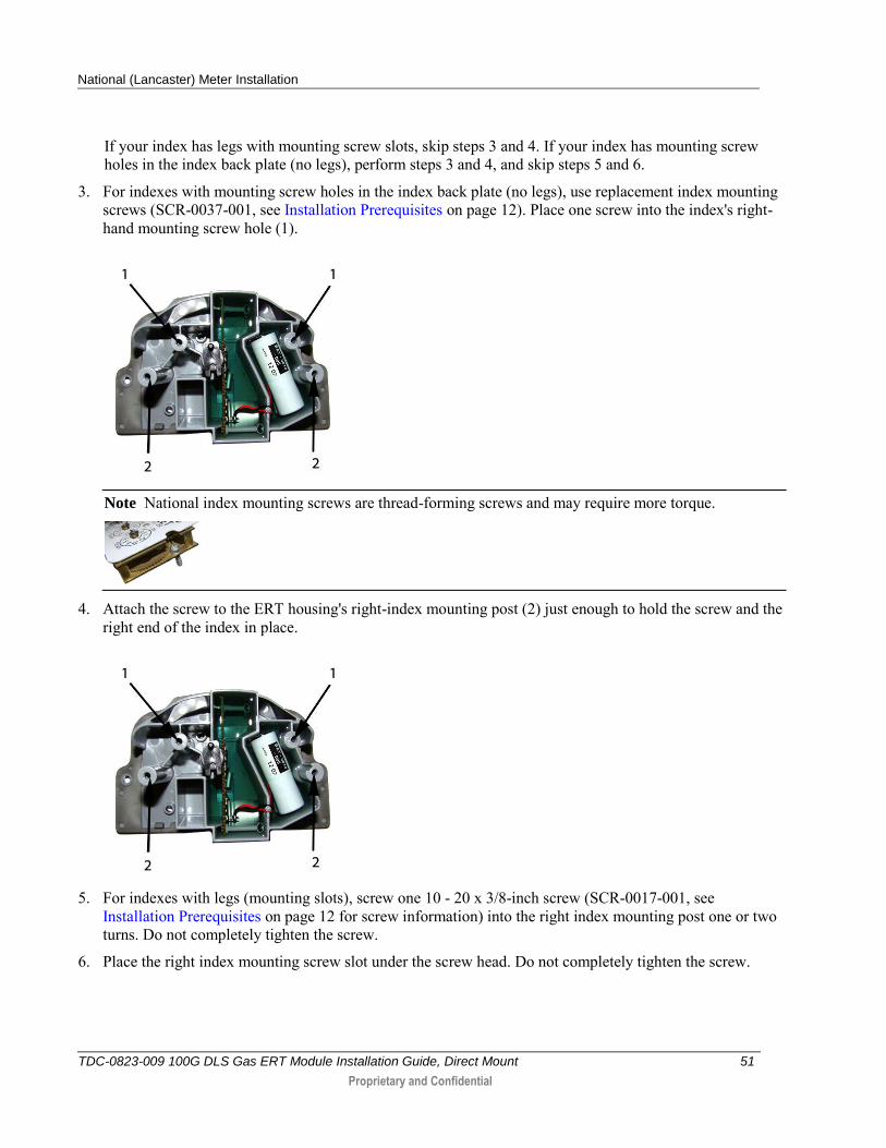
1. Separate the 100G DLS housing from the cover by pulling the cover straight out from the housing.
2. Set the ERT cover aside where it will not be damaged or fill with rain, dirt, or snow. You will use the
cover later in this installation procedure.
Caution Use only dial-type indexes from National, Actaris, Schlumberger, or Sprague meters with the 100G DLS. Indexes with bow-tie shaped wrigglers are not compatible with the 100G DLS. You must use a compatible index.
Note National (Lancaster) meter indexes are available in different models:
Some National meter indexes have index legs to mount the index on the meter or ERT. Some indexes have both legs and index mounting holes and some have just mounting holes. Mounting methods are dependent on the index. Index types require different mounting screws to attach the index to the 100G DLS housing (see Installation Prerequisites on page 12). Indexes with legs must be mounted to the ERT housing mounting posts. Indexes with mounting holes must be attached to the ERT housing's bracket mounting posts.
National (Lancaster) Meter Installation
TDC-0823-009 100G DLS Gas ERT Module Installation Guide, Direct Mount 51
Proprietary and Confidential
If your index has legs with mounting screw slots, skip steps 3 and 4. If your index has mounting screw holes in the index back plate (no legs), perform steps 3 and 4, and skip steps 5 and 6.
3. For indexes with mounting screw holes in the index back plate (no legs), use replacement index mounting screws (SCR-0037-001, see Installation Prerequisites on page 12). Place one screw into the index's right-hand mounting screw hole (1).
Note National index mounting screws are thread-forming screws and may require more torque.
4. Attach the screw to the ERT housing's right-index mounting post (2) just enough to hold the screw and the right end of the index in place.
5. For indexes with legs (mounting slots), screw one 10 - 20 x 3/8-inch screw (SCR-0017-001, see
Installation Prerequisites on page 12 for screw information) into the right index mounting post one or two turns. Do not completely tighten the screw.
6. Place the right index mounting screw slot under the screw head. Do not completely tighten the screw.
National (Lancaster) Meter Installation
TDC-0823-009 100G DLS Gas ERT Module Installation Guide, Direct Mount 52
Proprietary and Confidential
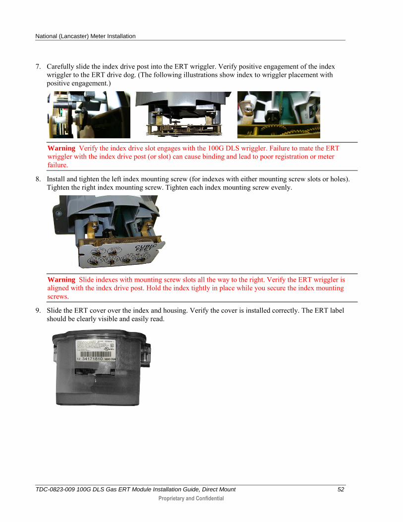
7. Carefully slide the index drive post into the ERT wriggler. Verify positive engagement of the index wriggler to the ERT drive dog. (The following illustrations show index to wriggler placement with positive engagement.)
Warning Verify the index drive slot engages with the 100G DLS wriggler. Failure to mate the ERT wriggler with the index drive post (or slot) can cause binding and lead to poor registration or meter failure.
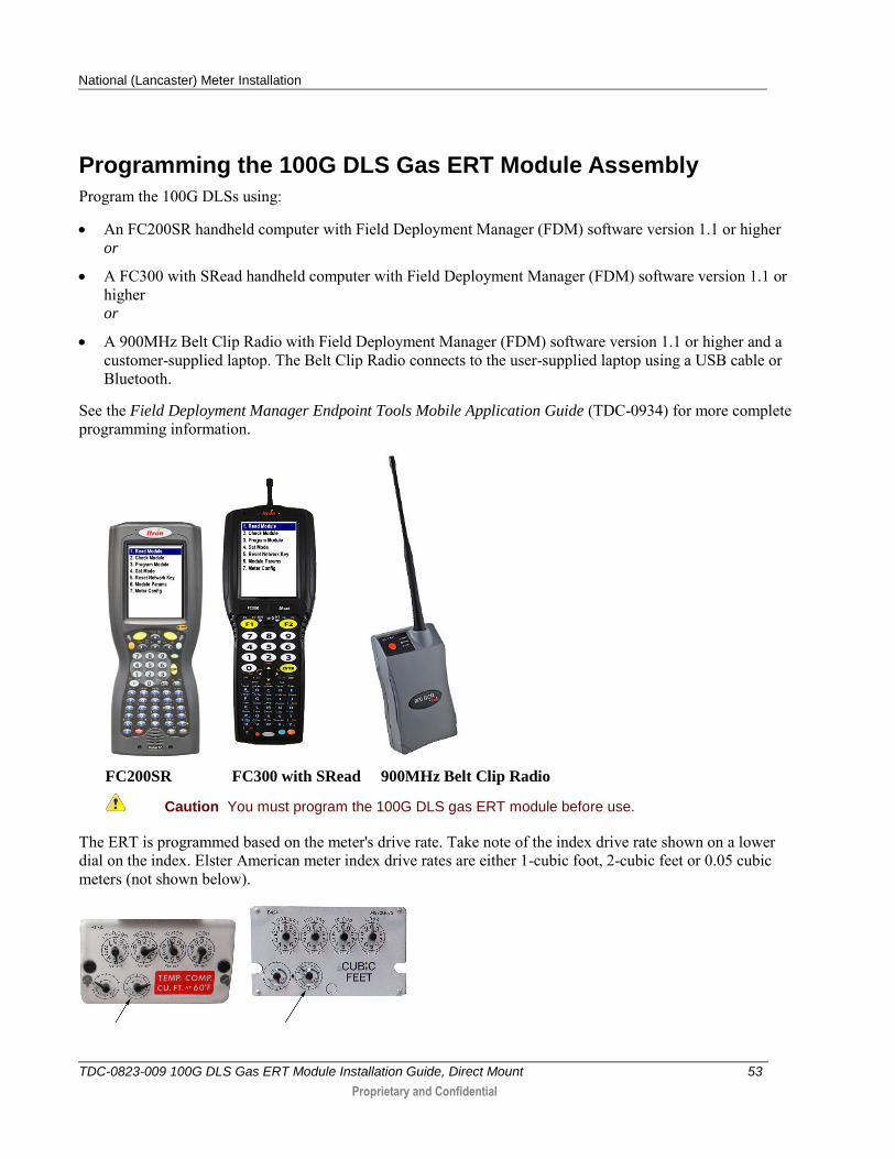
8. Install and tighten the left index mounting screw (for indexes with either mounting screw slots or holes). Tighten the right index mounting screw. Tighten each index mounting screw evenly.
Warning Slide indexes with mounting screw slots all the way to the right. Verify the ERT wriggler is aligned with the index drive post. Hold the index tightly in place while you secure the index mounting screws.
9. Slide the ERT cover over the index and housing. Verify the cover is installed correctly. The ERT label should be clearly visible and easily read.
National (Lancaster) Meter Installation
TDC-0823-009 100G DLS Gas ERT Module Installation Guide, Direct Mount 53
Proprietary and Confidential
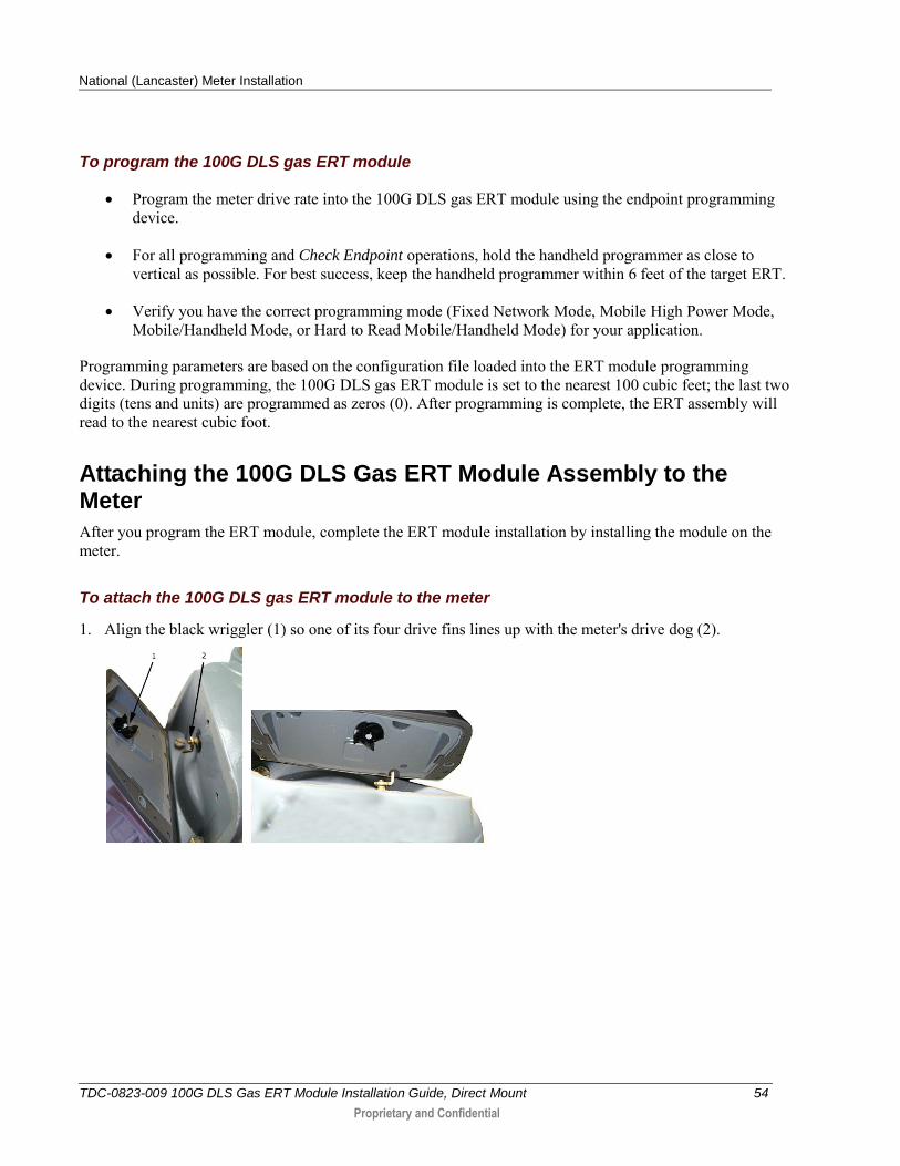
Programming the 100G DLS Gas ERT Module Assembly
Program the 100G DLSs using:
An FC200SR handheld computer with Field Deployment Manager (FDM) software version 1.1 or higher or
A FC300 with SRead handheld computer with Field Deployment Manager (FDM) software version 1.1 or higher or
A 900MHz Belt Clip Radio with Field Deployment Manager (FDM) software version 1.1 or higher and a customer-supplied laptop. The Belt Clip Radio connects to the user-supplied laptop using a USB cable or Bluetooth.
See the Field Deployment Manager Endpoint Tools Mobile Application Guide (TDC-0934) for more complete programming information.
FC200SR FC300 with SRead 900MHz Belt Clip Radio
Caution You must program the 100G DLS gas ERT module before use.
The ERT is programmed based on the meter's drive rate. Take note of the index drive rate shown on a lower dial on the index. Elster American meter index drive rates are either 1-cubic foot, 2-cubic feet or 0.05 cubic meters (not shown below).
National (Lancaster) Meter Installation
TDC-0823-009 100G DLS Gas ERT Module Installation Guide, Direct Mount 54
Proprietary and Confidential
To program the 100G DLS gas ERT module
Program the meter drive rate into the 100G DLS gas ERT module using the endpoint programming device.
For all programming and Check Endpoint operations, hold the handheld programmer as close to vertical as possible. For best success, keep the handheld programmer within 6 feet of the target ERT.
Verify you have the correct programming mode (Fixed Network Mode, Mobile High Power Mode, Mobile/Handheld Mode, or Hard to Read Mobile/Handheld Mode) for your application.
Programming parameters are based on the configuration file loaded into the ERT module programming device. During programming, the 100G DLS gas ERT module is set to the nearest 100 cubic feet; the last two digits (tens and units) are programmed as zeros (0). After programming is complete, the ERT assembly will read to the nearest cubic foot.
Attaching the 100G DLS Gas ERT Module Assembly to the Meter
After you program the ERT module, complete the ERT module installation by installing the module on the meter.
To attach the 100G DLS gas ERT module to the meter
1. Align the black wriggler (1) so one of its four drive fins lines up with the meter's drive dog (2).
National (Lancaster) Meter Installation
TDC-0823-009 100G DLS Gas ERT Module Installation Guide, Direct Mount 55
Proprietary and Confidential
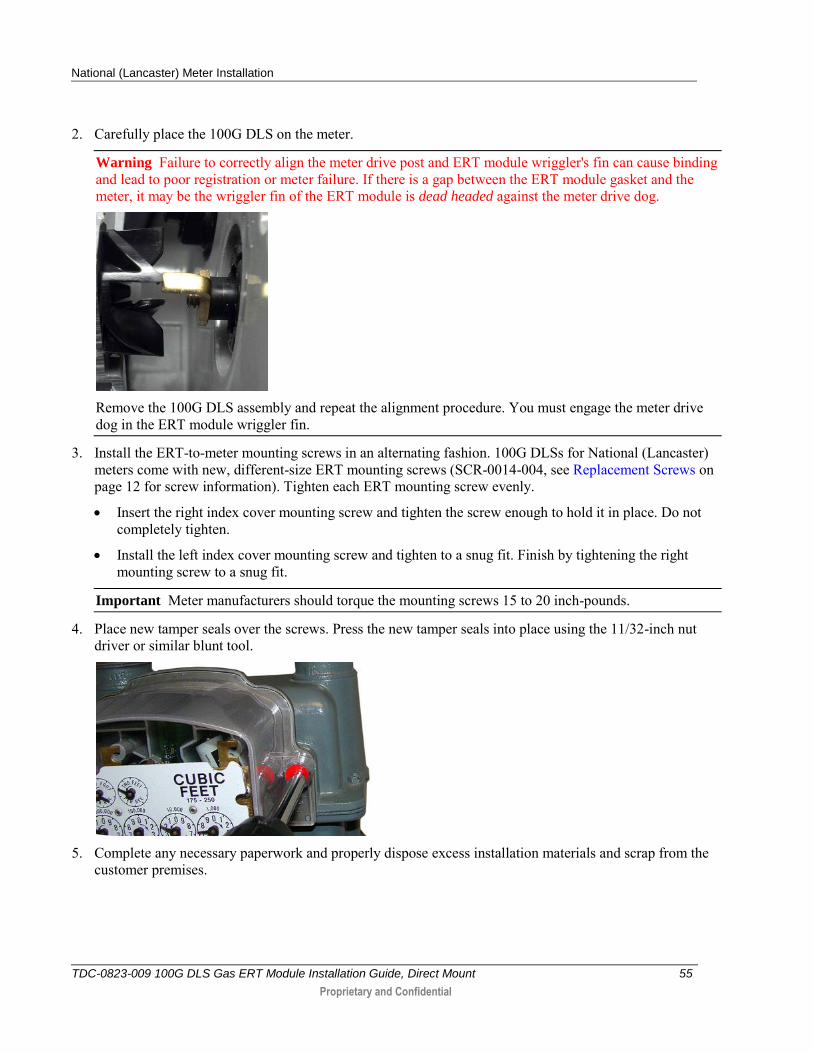
2. Carefully place the 100G DLS on the meter.
Warning Failure to correctly align the meter drive post and ERT module wriggler's fin can cause binding and lead to poor registration or meter failure. If there is a gap between the ERT module gasket and the meter, it may be the wriggler fin of the ERT module is dead headed against the meter drive dog.
Remove the 100G DLS assembly and repeat the alignment procedure. You must engage the meter drive dog in the ERT module wriggler fin.
3. Install the ERT-to-meter mounting screws in an alternating fashion. 100G DLSs for National (Lancaster) meters come with new, different-size ERT mounting screws (SCR-0014-004, see Replacement Screws on page 12 for screw information). Tighten each ERT mounting screw evenly.
Insert the right index cover mounting screw and tighten the screw enough to hold it in place. Do not completely tighten.
Install the left index cover mounting screw and tighten to a snug fit. Finish by tightening the right mounting screw to a snug fit.
Important Meter manufacturers should torque the mounting screws 15 to 20 inch-pounds.
4. Place new tamper seals over the screws. Press the new tamper seals into place using the 11/32-inch nut driver or similar blunt tool.
5. Complete any necessary paperwork and properly dispose excess installation materials and scrap from the
customer premises.
National (Lancaster) Meter Installation
TDC-0823-009 100G DLS Gas ERT Module Installation Guide, Direct Mount 56
Proprietary and Confidential
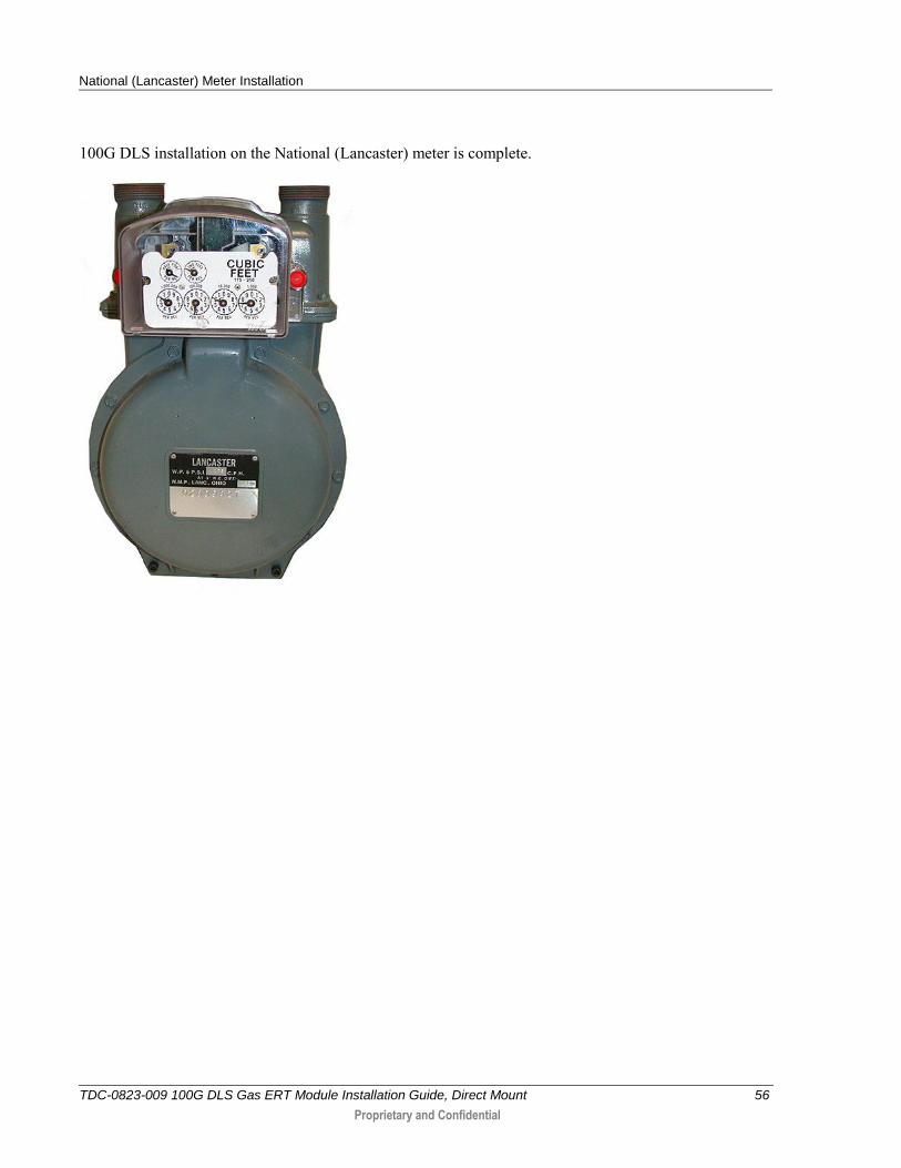
100G DLS installation on the National (Lancaster) meter is complete.
TDC-0823-009 100G DLS Gas ERT Module Installation Guide, Direct Mount 57
Proprietary and Confidential
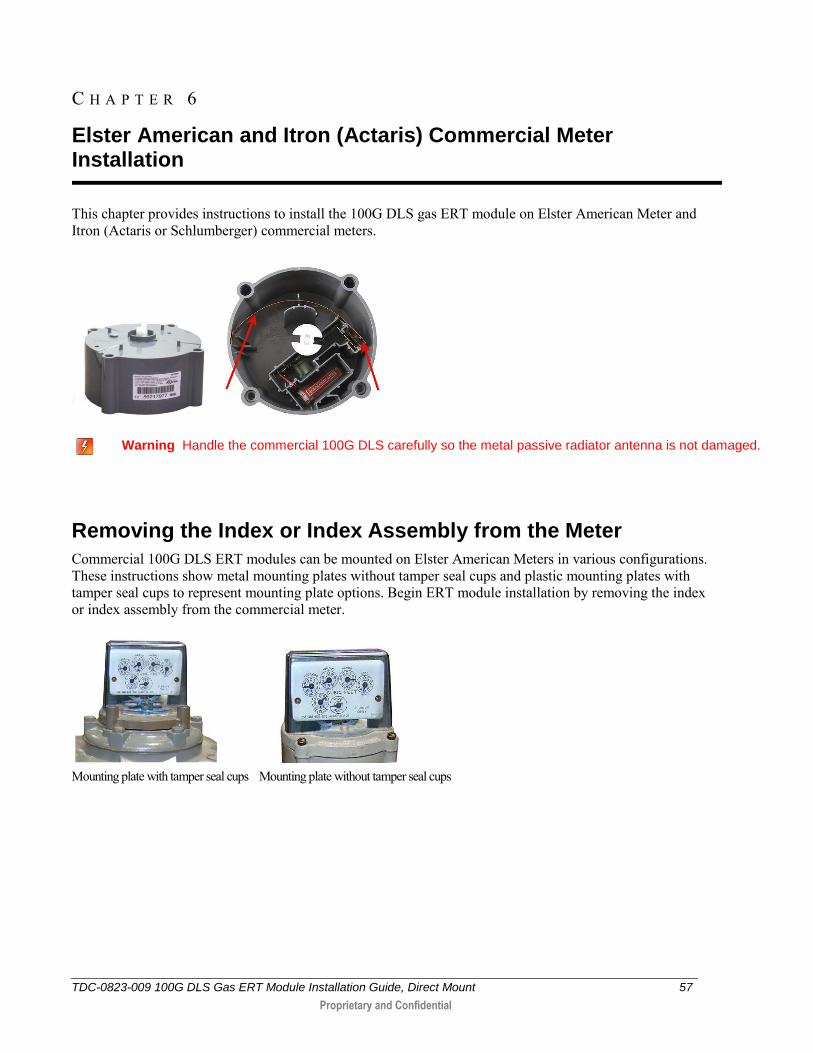
This chapter provides instructions to install the 100G DLS gas ERT module on Elster American Meter and Itron (Actaris or Schlumberger) commercial meters.
Warning Handle the commercial 100G DLS carefully so the metal passive radiator antenna is not damaged.
Removing the Index or Index Assembly from the Meter
Commercial 100G DLS ERT modules can be mounted on Elster American Meters in various configurations. These instructions show metal mounting plates without tamper seal cups and plastic mounting plates with tamper seal cups to represent mounting plate options. Begin ERT module installation by removing the index or index assembly from the commercial meter.
Mounting plate with tamper seal cups Mounting plate without tamper seal cups
C H A P T E R 6
Elster American and Itron (Actaris) Commercial Meter Installation
Elster American and Itron (Actaris) Commercial Meter Installation
TDC-0823-009 100G DLS Gas ERT Module Installation Guide, Direct Mount 58
Proprietary and Confidential
Indexes may be mounted on the 100G DLS commercial Elster American Meter gas ERT without mounting plates.
Index covers may (or may not) have tamper seal cups (on the back of the cover) for added security. Index removal assumes the installer removes any tamper seals or wires before continuing with these instructions.
Note It may not be necessary to dismantle your commercial index assembly (index and cover). These instructions do not include index/cover assembly for those applications.
Some diaphragm commercial meters do not require an index assembly mounting plate. Indexes can be mounted directly to the ERT.
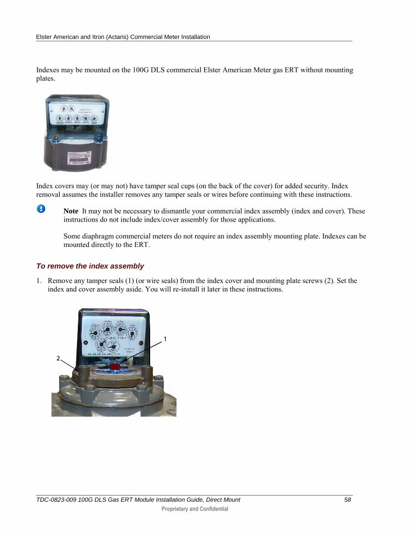
To remove the index assembly
1. Remove any tamper seals (1) (or wire seals) from the index cover and mounting plate screws (2). Set the index and cover assembly aside. You will re-install it later in these instructions.
Elster American and Itron (Actaris) Commercial Meter Installation
TDC-0823-009 100G DLS Gas ERT Module Installation Guide, Direct Mount 59
Proprietary and Confidential
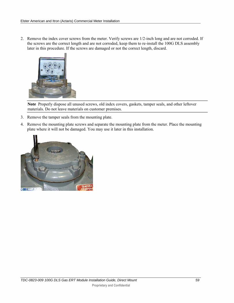
2. Remove the index cover screws from the meter. Verify screws are 1/2-inch long and are not corroded. If the screws are the correct length and are not corroded, keep them to re-install the 100G DLS assembly later in this procedure. If the screws are damaged or not the correct length, discard.
Note Properly dispose all unused screws, old index covers, gaskets, tamper seals, and other leftover materials. Do not leave materials on customer premises.
3. Remove the tamper seals from the mounting plate.
4. Remove the mounting plate screws and separate the mounting plate from the meter. Place the mounting plate where it will not be damaged. You may use it later in this installation.
Elster American and Itron (Actaris) Commercial Meter Installation
TDC-0823-009 100G DLS Gas ERT Module Installation Guide, Direct Mount 60
Proprietary and Confidential
Programming the 100G DLS Commercial Gas ERT Module Assembly
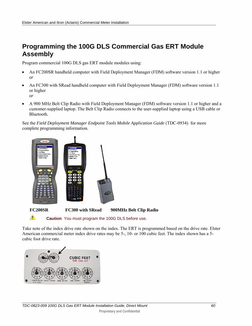
Program commercial 100G DLS gas ERT module modules using:
An FC200SR handheld computer with Field Deployment Manager (FDM) software version 1.1 or higher or
An FC300 with SRead handheld computer with Field Deployment Manager (FDM) software version 1.1 or higher or
A 900 MHz Belt Clip Radio with Field Deployment Manager (FDM) software version 1.1 or higher and a customer-supplied laptop. The Belt Clip Radio connects to the user-supplied laptop using a USB cable or Bluetooth.
See the Field Deployment Manager Endpoint Tools Mobile Application Guide (TDC-0934) for more complete programming information.
FC200SR FC300 with SRead 900MHz Belt Clip Radio
Caution You must program the 100G DLS before use.
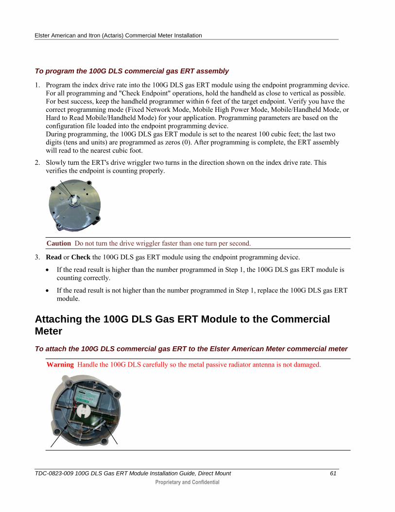
Take note of the index drive rate shown on the index. The ERT is programmed based on the drive rate. Elster American commercial meter index drive rates may be 5-, 10- or 100 cubic feet. The index shown has a 5-cubic foot drive rate.
Elster American and Itron (Actaris) Commercial Meter Installation
TDC-0823-009 100G DLS Gas ERT Module Installation Guide, Direct Mount 61
Proprietary and Confidential
To program the 100G DLS commercial gas ERT assembly
1. Program the index drive rate into the 100G DLS gas ERT module using the endpoint programming device. For all programming and "Check Endpoint" operations, hold the handheld as close to vertical as possible. For best success, keep the handheld programmer within 6 feet of the target endpoint. Verify you have the correct programming mode (Fixed Network Mode, Mobile High Power Mode, Mobile/Handheld Mode, or Hard to Read Mobile/Handheld Mode) for your application. Programming parameters are based on the configuration file loaded into the endpoint programming device. During programming, the 100G DLS gas ERT module is set to the nearest 100 cubic feet; the last two digits (tens and units) are programmed as zeros (0). After programming is complete, the ERT assembly will read to the nearest cubic foot.
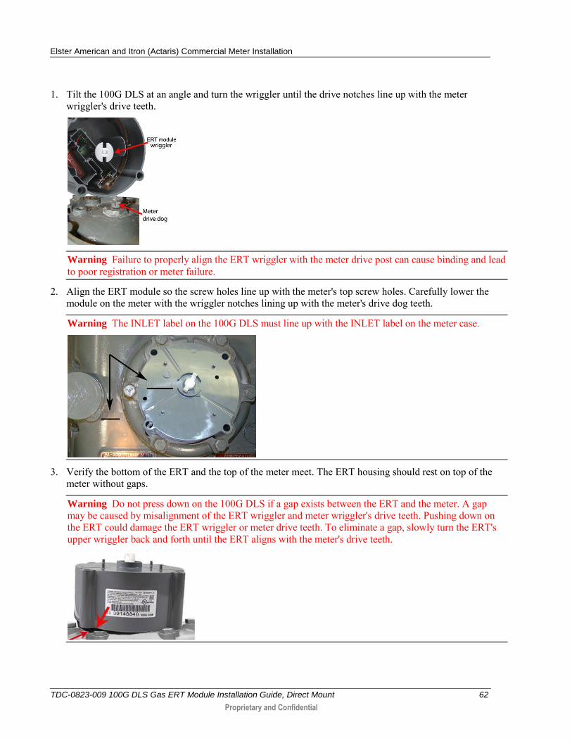
2. Slowly turn the ERT's drive wriggler two turns in the direction shown on the index drive rate. This verifies the endpoint is counting properly.
Caution Do not turn the drive wriggler faster than one turn per second.
3. Read or Check the 100G DLS gas ERT module using the endpoint programming device.
If the read result is higher than the number programmed in Step 1, the 100G DLS gas ERT module is counting correctly.
If the read result is not higher than the number programmed in Step 1, replace the 100G DLS gas ERT module.
Attaching the 100G DLS Gas ERT Module to the Commercial Meter
To attach the 100G DLS commercial gas ERT to the Elster American Meter commercial meter
Warning Handle the 100G DLS carefully so the metal passive radiator antenna is not damaged.
Elster American and Itron (Actaris) Commercial Meter Installation
TDC-0823-009 100G DLS Gas ERT Module Installation Guide, Direct Mount 62
Proprietary and Confidential
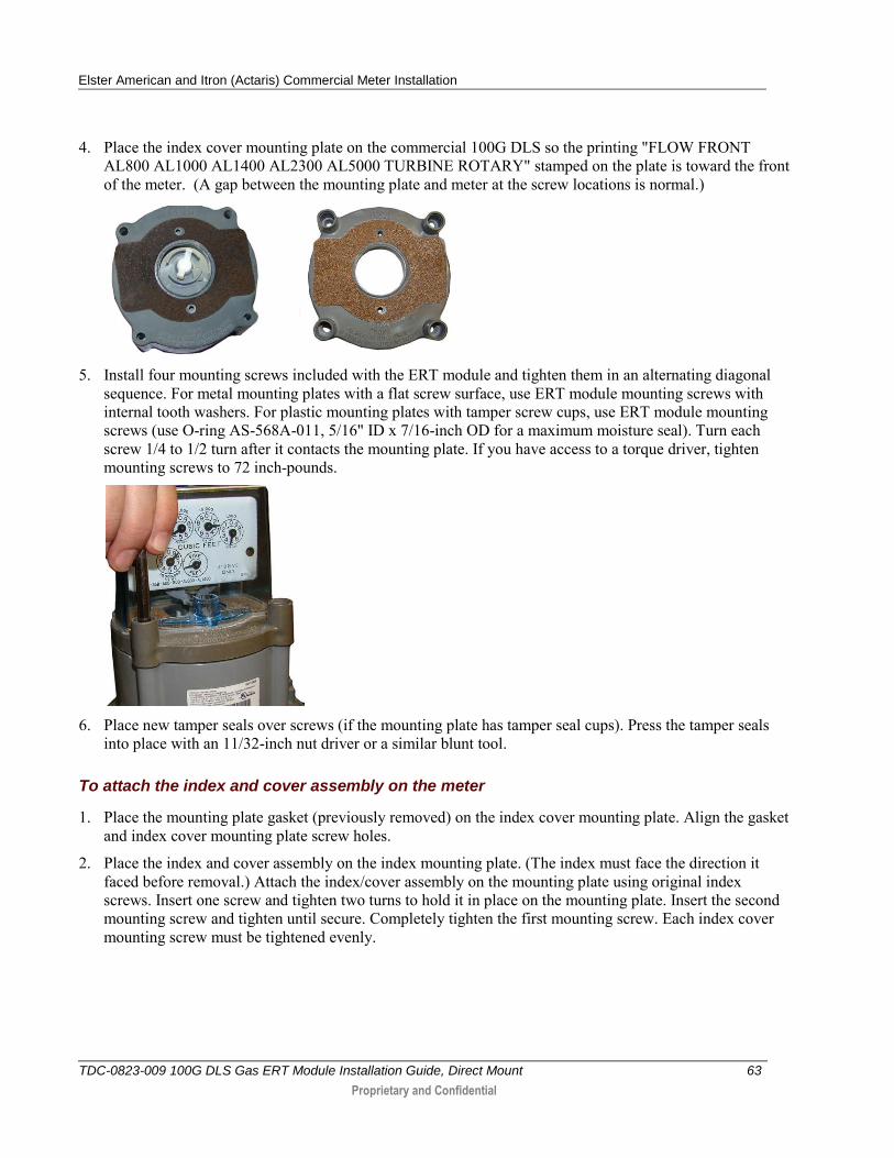
1. Tilt the 100G DLS at an angle and turn the wriggler until the drive notches line up with the meter wriggler's drive teeth.
Warning Failure to properly align the ERT wriggler with the meter drive post can cause binding and lead to poor registration or meter failure.
2. Align the ERT module so the screw holes line up with the meter's top screw holes. Carefully lower the module on the meter with the wriggler notches lining up with the meter's drive dog teeth.
Warning The INLET label on the 100G DLS must line up with the INLET label on the meter case.
3. Verify the bottom of the ERT and the top of the meter meet. The ERT housing should rest on top of the meter without gaps.
Warning Do not press down on the 100G DLS if a gap exists between the ERT and the meter. A gap may be caused by misalignment of the ERT wriggler and meter wriggler's drive teeth. Pushing down on the ERT could damage the ERT wriggler or meter drive teeth. To eliminate a gap, slowly turn the ERT's upper wriggler back and forth until the ERT aligns with the meter's drive teeth.
Elster American and Itron (Actaris) Commercial Meter Installation
TDC-0823-009 100G DLS Gas ERT Module Installation Guide, Direct Mount 63
Proprietary and Confidential
4. Place the index cover mounting plate on the commercial 100G DLS so the printing "FLOW FRONT AL800 AL1000 AL1400 AL2300 AL5000 TURBINE ROTARY" stamped on the plate is toward the front of the meter. (A gap between the mounting plate and meter at the screw locations is normal.)
5. Install four mounting screws included with the ERT module and tighten them in an alternating diagonal
sequence. For metal mounting plates with a flat screw surface, use ERT module mounting screws with internal tooth washers. For plastic mounting plates with tamper screw cups, use ERT module mounting screws (use O-ring AS-568A-011, 5/16" ID x 7/16-inch OD for a maximum moisture seal). Turn each screw 1/4 to 1/2 turn after it contacts the mounting plate. If you have access to a torque driver, tighten mounting screws to 72 inch-pounds.
6. Place new tamper seals over screws (if the mounting plate has tamper seal cups). Press the tamper seals
into place with an 11/32-inch nut driver or a similar blunt tool.
To attach the index and cover assembly on the meter
1. Place the mounting plate gasket (previously removed) on the index cover mounting plate. Align the gasket and index cover mounting plate screw holes.
2. Place the index and cover assembly on the index mounting plate. (The index must face the direction it faced before removal.) Attach the index/cover assembly on the mounting plate using original index screws. Insert one screw and tighten two turns to hold it in place on the mounting plate. Insert the second mounting screw and tighten until secure. Completely tighten the first mounting screw. Each index cover mounting screw must be tightened evenly.
Elster American and Itron (Actaris) Commercial Meter Installation
TDC-0823-009 100G DLS Gas ERT Module Installation Guide, Direct Mount 64
Proprietary and Confidential
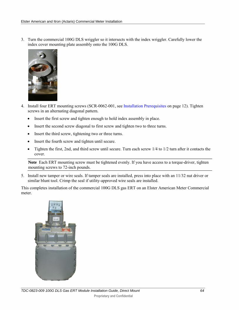
3. Turn the commercial 100G DLS wriggler so it intersects with the index wriggler. Carefully lower the index cover mounting plate assembly onto the 100G DLS.
4. Install four ERT mounting screws (SCR-0062-001, see Installation Prerequisites on page 12). Tighten
screws in an alternating diagonal pattern.
Insert the first screw and tighten enough to hold index assembly in place.
Insert the second screw diagonal to first screw and tighten two to three turns.
Insert the third screw, tightening two or three turns.
Insert the fourth screw and tighten until secure.
Tighten the first, 2nd, and third screw until secure. Turn each screw 1/4 to 1/2 turn after it contacts the cover.
Note Each ERT mounting screw must be tightened evenly. If you have access to a torque-driver, tighten mounting screws to 72-inch pounds.
5. Install new tamper or wire seals. If tamper seals are installed, press into place with an 11/32 nut driver or similar blunt tool. Crimp the seal if utility-approved wire seals are installed.
This completes installation of the commercial 100G DLS gas ERT on an Elster American Meter Commercial meter.
Elster American and Itron (Actaris) Commercial Meter Installation
TDC-0823-009 100G DLS Gas ERT Module Installation Guide, Direct Mount 65
Proprietary and Confidential
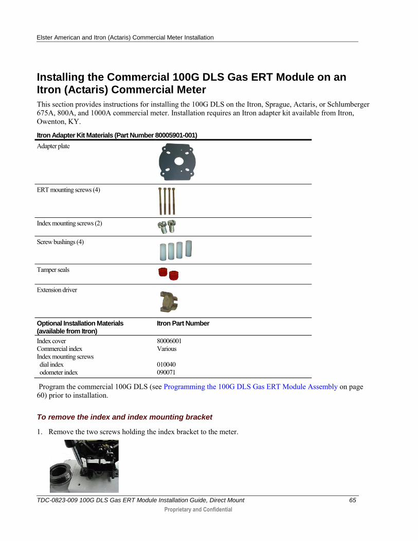
Installing the Commercial 100G DLS Gas ERT Module on an Itron (Actaris) Commercial Meter
This section provides instructions for installing the 100G DLS on the Itron, Sprague, Actaris, or Schlumberger 675A, 800A, and 1000A commercial meter. Installation requires an Itron adapter kit available from Itron, Owenton, KY.
Itron Adapter Kit Materials (Part Number 80005901-001)
Adapter plate
ERT mounting screws (4)
Index mounting screws (2)
Screw bushings (4)
Tamper seals
Extension driver
Optional Installation Materials (available from Itron)
Itron Part Number
Index cover Commercial index Index mounting screws dial index odometer index
80006001 Various 010040 090071
Program the commercial 100G DLS (see Programming the 100G DLS Gas ERT Module Assembly on page 60) prior to installation.
To remove the index and index mounting bracket
1. Remove the two screws holding the index bracket to the meter.
Elster American and Itron (Actaris) Commercial Meter Installation
TDC-0823-009 100G DLS Gas ERT Module Installation Guide, Direct Mount 66
Proprietary and Confidential
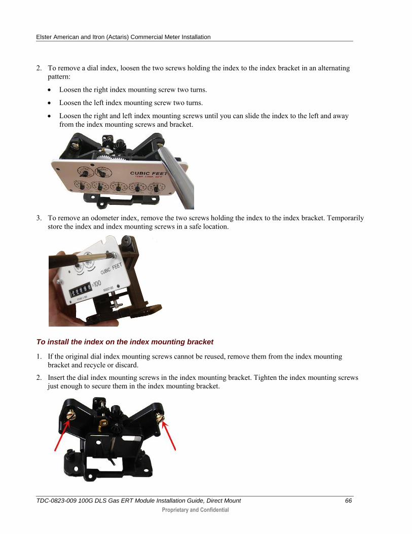
2. To remove a dial index, loosen the two screws holding the index to the index bracket in an alternating pattern:
Loosen the right index mounting screw two turns.
Loosen the left index mounting screw two turns.
Loosen the right and left index mounting screws until you can slide the index to the left and away from the index mounting screws and bracket.
3. To remove an odometer index, remove the two screws holding the index to the index bracket. Temporarily
store the index and index mounting screws in a safe location.
To install the index on the index mounting bracket
1. If the original dial index mounting screws cannot be reused, remove them from the index mounting bracket and recycle or discard.
2. Insert the dial index mounting screws in the index mounting bracket. Tighten the index mounting screws just enough to secure them in the index mounting bracket.
Elster American and Itron (Actaris) Commercial Meter Installation
TDC-0823-009 100G DLS Gas ERT Module Installation Guide, Direct Mount 67
Proprietary and Confidential
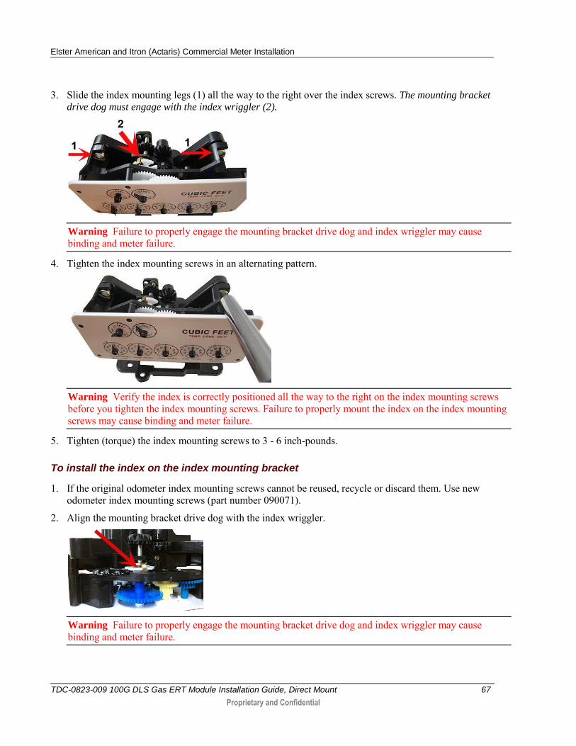
3. Slide the index mounting legs (1) all the way to the right over the index screws. The mounting bracket
drive dog must engage with the index wriggler (2).
Warning Failure to properly engage the mounting bracket drive dog and index wriggler may cause binding and meter failure.
4. Tighten the index mounting screws in an alternating pattern.
Warning Verify the index is correctly positioned all the way to the right on the index mounting screws before you tighten the index mounting screws. Failure to properly mount the index on the index mounting screws may cause binding and meter failure.
5. Tighten (torque) the index mounting screws to 3 - 6 inch-pounds.
To install the index on the index mounting bracket
1. If the original odometer index mounting screws cannot be reused, recycle or discard them. Use new odometer index mounting screws (part number 090071).
2. Align the mounting bracket drive dog with the index wriggler.
Warning Failure to properly engage the mounting bracket drive dog and index wriggler may cause binding and meter failure.
Elster American and Itron (Actaris) Commercial Meter Installation
TDC-0823-009 100G DLS Gas ERT Module Installation Guide, Direct Mount 68
Proprietary and Confidential
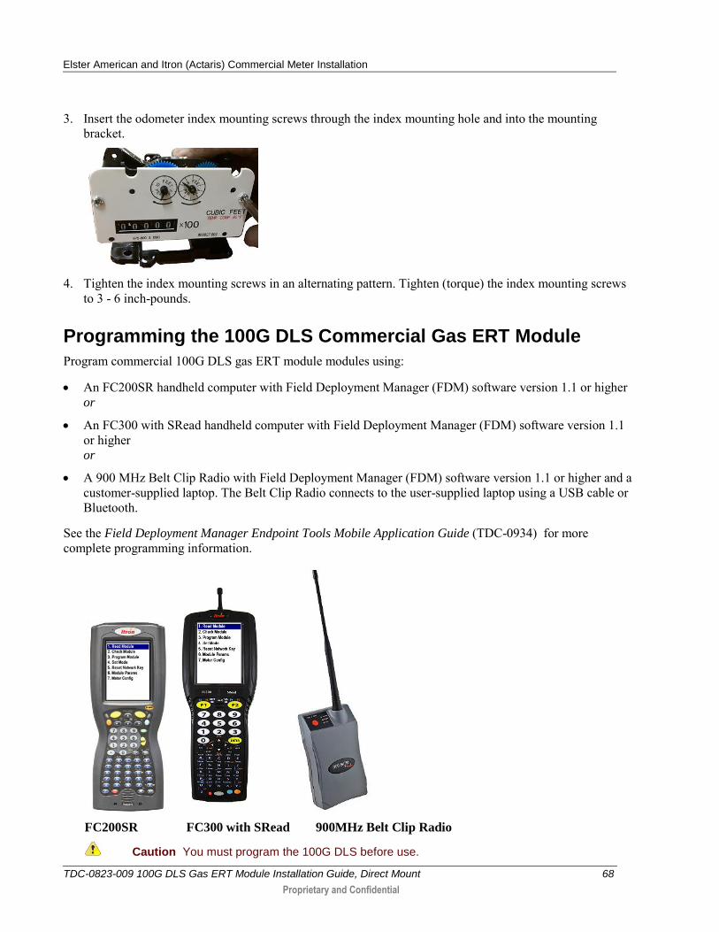
3. Insert the odometer index mounting screws through the index mounting hole and into the mounting bracket.
4. Tighten the index mounting screws in an alternating pattern. Tighten (torque) the index mounting screws
to 3 - 6 inch-pounds.
Programming the 100G DLS Commercial Gas ERT Module
Program commercial 100G DLS gas ERT module modules using:
An FC200SR handheld computer with Field Deployment Manager (FDM) software version 1.1 or higher or
An FC300 with SRead handheld computer with Field Deployment Manager (FDM) software version 1.1 or higher or
A 900 MHz Belt Clip Radio with Field Deployment Manager (FDM) software version 1.1 or higher and a customer-supplied laptop. The Belt Clip Radio connects to the user-supplied laptop using a USB cable or Bluetooth.
See the Field Deployment Manager Endpoint Tools Mobile Application Guide (TDC-0934) for more complete programming information.
FC200SR FC300 with SRead 900MHz Belt Clip Radio
Caution You must program the 100G DLS before use.
Elster American and Itron (Actaris) Commercial Meter Installation
TDC-0823-009 100G DLS Gas ERT Module Installation Guide, Direct Mount 69
Proprietary and Confidential
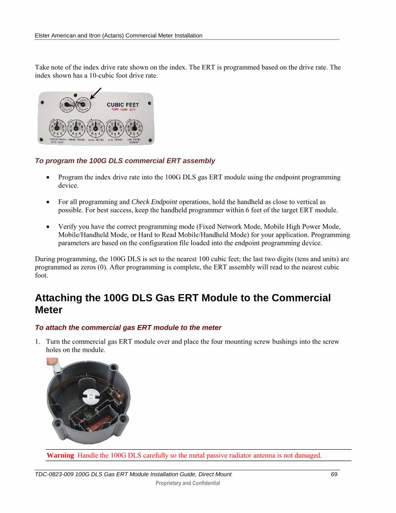
Take note of the index drive rate shown on the index. The ERT is programmed based on the drive rate. The index shown has a 10-cubic foot drive rate.
To program the 100G DLS commercial ERT assembly
Program the index drive rate into the 100G DLS gas ERT module using the endpoint programming device.
For all programming and Check Endpoint operations, hold the handheld as close to vertical as possible. For best success, keep the handheld programmer within 6 feet of the target ERT module.
Verify you have the correct programming mode (Fixed Network Mode, Mobile High Power Mode, Mobile/Handheld Mode, or Hard to Read Mobile/Handheld Mode) for your application. Programming parameters are based on the configuration file loaded into the endpoint programming device.
During programming, the 100G DLS is set to the nearest 100 cubic feet; the last two digits (tens and units) are programmed as zeros (0). After programming is complete, the ERT assembly will read to the nearest cubic foot.
Attaching the 100G DLS Gas ERT Module to the Commercial Meter
To attach the commercial gas ERT module to the meter
1. Turn the commercial gas ERT module over and place the four mounting screw bushings into the screw holes on the module.
Warning Handle the 100G DLS carefully so the metal passive radiator antenna is not damaged.
Elster American and Itron (Actaris) Commercial Meter Installation
TDC-0823-009 100G DLS Gas ERT Module Installation Guide, Direct Mount 70
Proprietary and Confidential
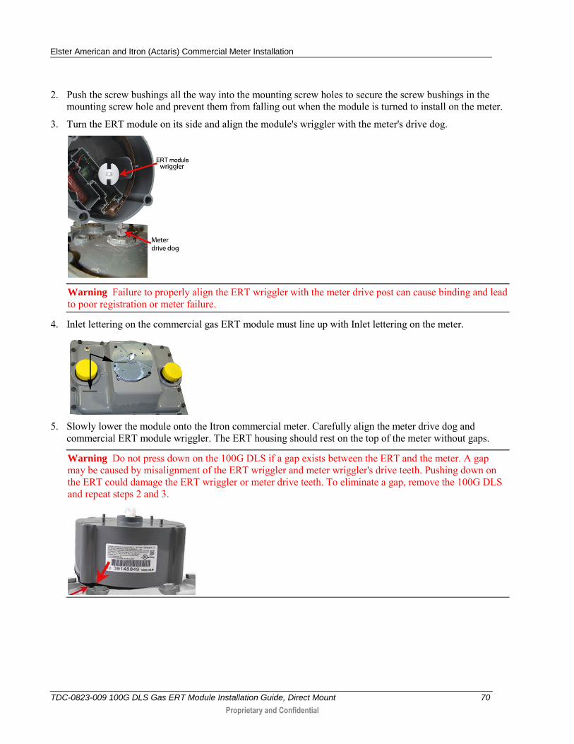
2. Push the screw bushings all the way into the mounting screw holes to secure the screw bushings in the mounting screw hole and prevent them from falling out when the module is turned to install on the meter.
3. Turn the ERT module on its side and align the module's wriggler with the meter's drive dog.
Warning Failure to properly align the ERT wriggler with the meter drive post can cause binding and lead to poor registration or meter failure.
4. Inlet lettering on the commercial gas ERT module must line up with Inlet lettering on the meter.
5. Slowly lower the module onto the Itron commercial meter. Carefully align the meter drive dog and
commercial ERT module wriggler. The ERT housing should rest on the top of the meter without gaps.
Warning Do not press down on the 100G DLS if a gap exists between the ERT and the meter. A gap may be caused by misalignment of the ERT wriggler and meter wriggler's drive teeth. Pushing down on the ERT could damage the ERT wriggler or meter drive teeth. To eliminate a gap, remove the 100G DLS and repeat steps 2 and 3.
Elster American and Itron (Actaris) Commercial Meter Installation
TDC-0823-009 100G DLS Gas ERT Module Installation Guide, Direct Mount 71
Proprietary and Confidential
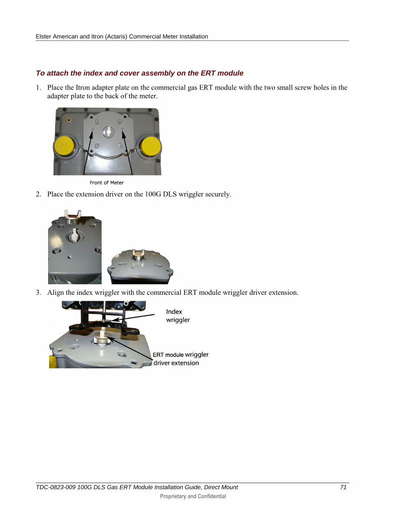
To attach the index and cover assembly on the ERT module
1. Place the Itron adapter plate on the commercial gas ERT module with the two small screw holes in the adapter plate to the back of the meter.
2. Place the extension driver on the 100G DLS wriggler securely.
3. Align the index wriggler with the commercial ERT module wriggler driver extension.
Elster American and Itron (Actaris) Commercial Meter Installation
TDC-0823-009 100G DLS Gas ERT Module Installation Guide, Direct Mount 72
Proprietary and Confidential
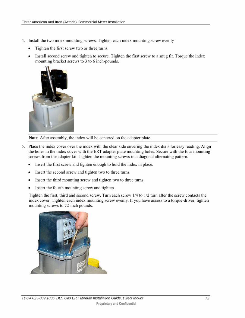
4. Install the two index mounting screws. Tighten each index mounting screw evenly
Tighten the first screw two or three turns.
Install second screw and tighten to secure. Tighten the first screw to a snug fit. Torque the index mounting bracket screws to 3 to 6 inch-pounds.
Note After assembly, the index will be centered on the adapter plate.
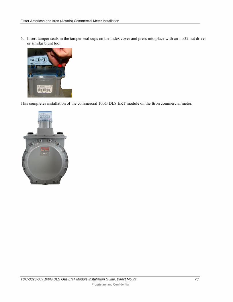
5. Place the index cover over the index with the clear side covering the index dials for easy reading. Align the holes in the index cover with the ERT adapter plate mounting holes. Secure with the four mounting screws from the adapter kit. Tighten the mounting screws in a diagonal alternating pattern.
Insert the first screw and tighten enough to hold the index in place.
Insert the second screw and tighten two to three turns.
Insert the third mounting screw and tighten two to three turns.
Insert the fourth mounting screw and tighten.
Tighten the first, third and second screw. Turn each screw 1/4 to 1/2 turn after the screw contacts the index cover. Tighten each index mounting screw evenly. If you have access to a torque-driver, tighten mounting screws to 72-inch pounds.
Elster American and Itron (Actaris) Commercial Meter Installation
TDC-0823-009 100G DLS Gas ERT Module Installation Guide, Direct Mount 73
Proprietary and Confidential
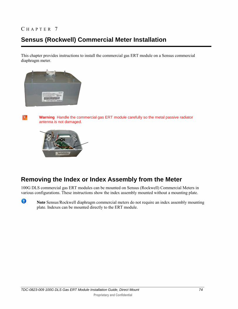
6. Insert tamper seals in the tamper seal cups on the index cover and press into place with an 11/32 nut driver or similar blunt tool.
This completes installation of the commercial 100G DLS ERT module on the Itron commercial meter.
TDC-0823-009 100G DLS Gas ERT Module Installation Guide, Direct Mount 74
Proprietary and Confidential
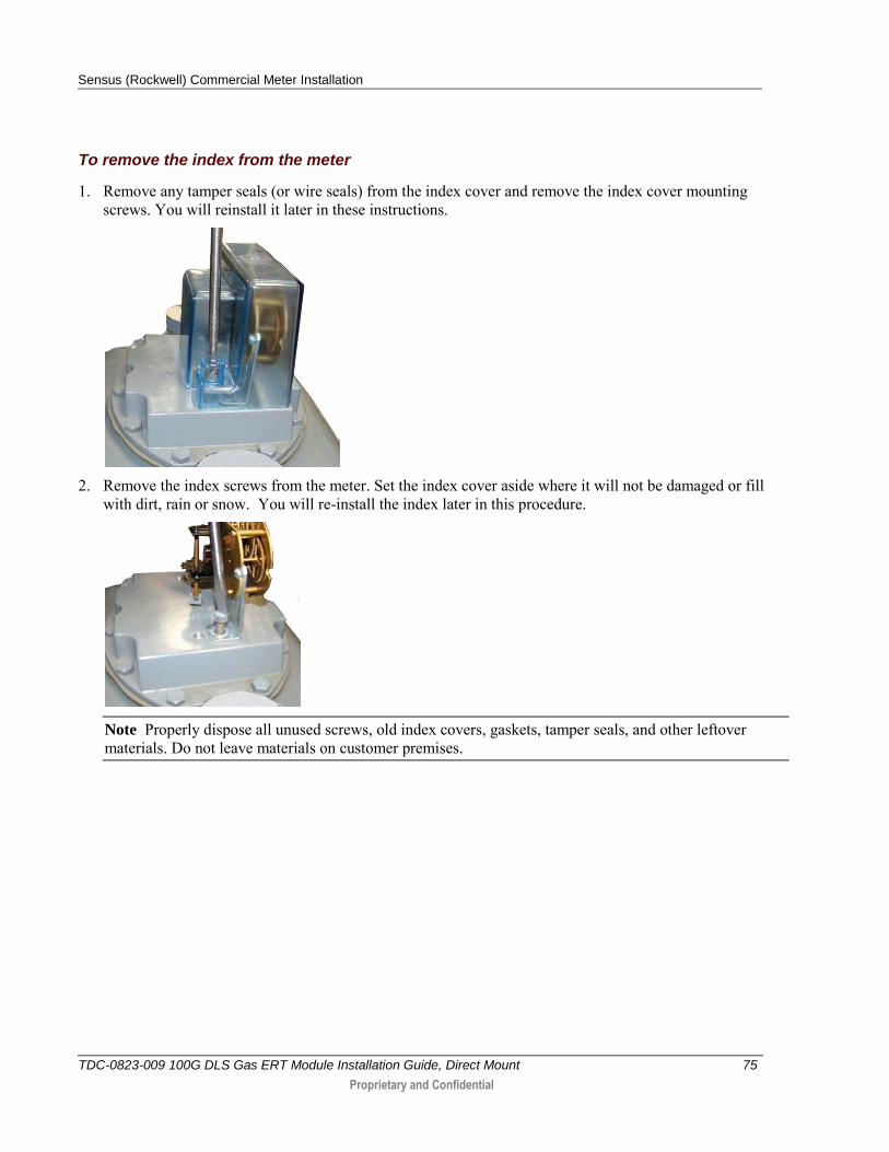
This chapter provides instructions to install the commercial gas ERT module on a Sensus commercial diaphragm meter.
Warning Handle the commercial gas ERT module carefully so the metal passive radiator antenna is not damaged.
Removing the Index or Index Assembly from the Meter
100G DLS commercial gas ERT modules can be mounted on Sensus (Rockwell) Commercial Meters in various configurations. These instructions show the index assembly mounted without a mounting plate.
Note Sensus/Rockwell diaphragm commercial meters do not require an index assembly mounting plate. Indexes can be mounted directly to the ERT module.
C H A P T E R 7
Sensus (Rockwell) Commercial Meter Installation
Sensus (Rockwell) Commercial Meter Installation
TDC-0823-009 100G DLS Gas ERT Module Installation Guide, Direct Mount 75
Proprietary and Confidential
To remove the index from the meter
1. Remove any tamper seals (or wire seals) from the index cover and remove the index cover mounting screws. You will reinstall it later in these instructions.
2. Remove the index screws from the meter. Set the index cover aside where it will not be damaged or fill
with dirt, rain or snow. You will re-install the index later in this procedure.
Note Properly dispose all unused screws, old index covers, gaskets, tamper seals, and other leftover materials. Do not leave materials on customer premises.
Sensus (Rockwell) Commercial Meter Installation
TDC-0823-009 100G DLS Gas ERT Module Installation Guide, Direct Mount 76
Proprietary and Confidential
Programming the 100G DLS Gas ERT Module
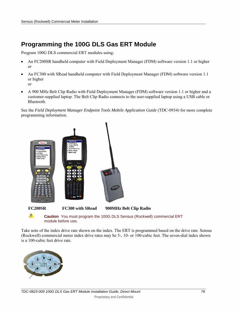
Program 100G DLS commercial ERT modules using:
An FC200SR handheld computer with Field Deployment Manager (FDM) software version 1.1 or higher or
An FC300 with SRead handheld computer with Field Deployment Manager (FDM) software version 1.1 or higher or
A 900 MHz Belt Clip Radio with Field Deployment Manager (FDM) software version 1.1 or higher and a customer-supplied laptop. The Belt Clip Radio connects to the user-supplied laptop using a USB cable or Bluetooth.
See the Field Deployment Manager Endpoint Tools Mobile Application Guide (TDC-0934) for more complete programming information.
FC200SR FC300 with SRead 900MHz Belt Clip Radio
Caution You must program the 100G DLS Sensus (Rockwell) commercial ERT module before use.
Take note of the index drive rate shown on the index. The ERT is programmed based on the drive rate. Sensus (Rockwell) commercial meter index drive rates may be 5-, 10- or 100-cubic feet. The seven-dial index shown is a 100-cubic feet drive rate.
Sensus (Rockwell) Commercial Meter Installation
TDC-0823-009 100G DLS Gas ERT Module Installation Guide, Direct Mount 77
Proprietary and Confidential
To program the commercial 100G DLS gas ERT module assembly
Program the index drive rate into the commercial ERT module using the endpoint programming device.
For all programming and Check Endpoint operations, hold the handheld programmer as close to vertical as possible. For best success, keep the handheld programmer within 6 feet of the target ERT module.
Verify you have the correct programming mode (Fixed Network Mode, Mobile High Power Mode, Mobile/Handheld Mode, or Hard to Read Mobile/Handheld Mode) for your application. Programming parameters are based on the configuration file loaded into the endpoint programming device.
During programming, the 100G DLS is set to the nearest 100 cubic feet; the last two digits (tens and units) are programmed as zeros (0). After programming is complete, the 100G DLS ERT module assembly will read to the nearest cubic foot.
Attaching the 100G DLS Gas ERT Module to a Sensus/Rockwell Commercial Diaphragm Meter
After the ERT module is programmed, complete the ERT module installation by attaching the commercial module to the commercial meter.
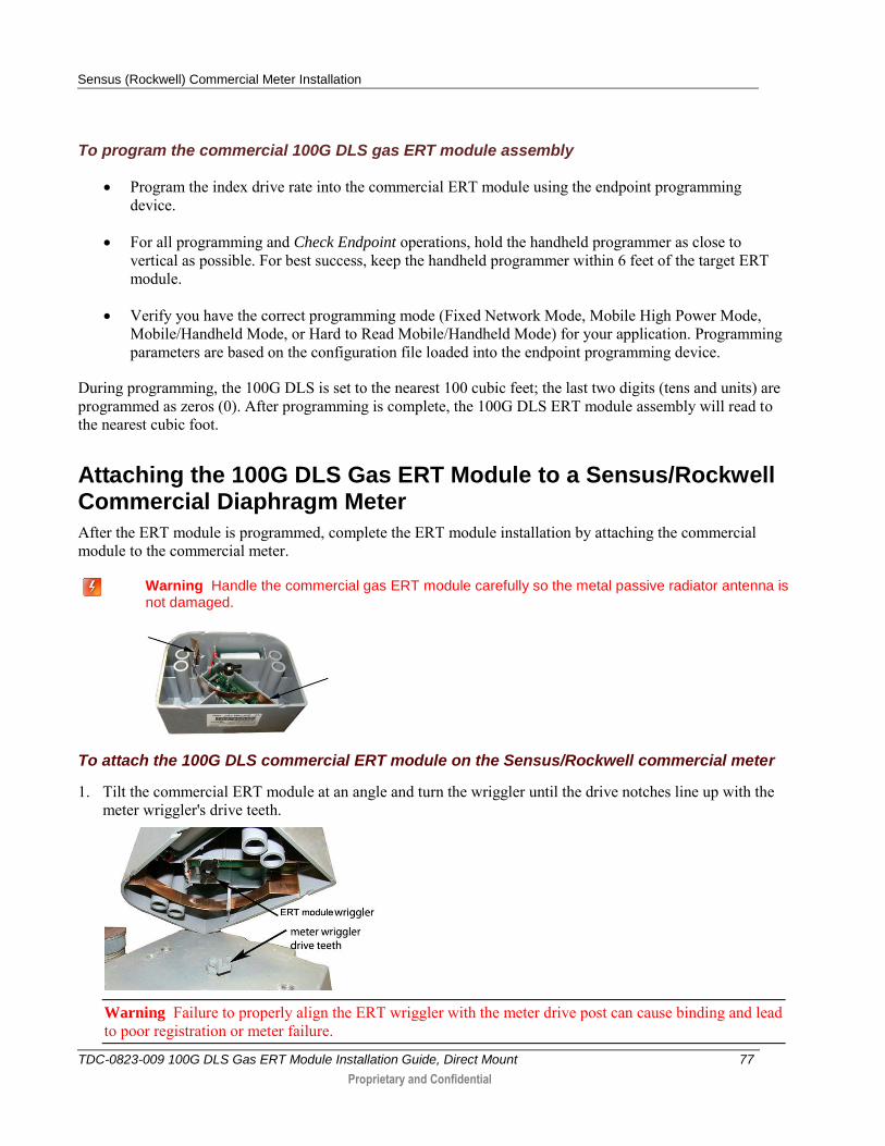
Warning Handle the commercial gas ERT module carefully so the metal passive radiator antenna is not damaged.
To attach the 100G DLS commercial ERT module on the Sensus/Rockwell commercial meter
1. Tilt the commercial ERT module at an angle and turn the wriggler until the drive notches line up with the meter wriggler's drive teeth.
Warning Failure to properly align the ERT wriggler with the meter drive post can cause binding and lead to poor registration or meter failure.
Sensus (Rockwell) Commercial Meter Installation
TDC-0823-009 100G DLS Gas ERT Module Installation Guide, Direct Mount 78
Proprietary and Confidential
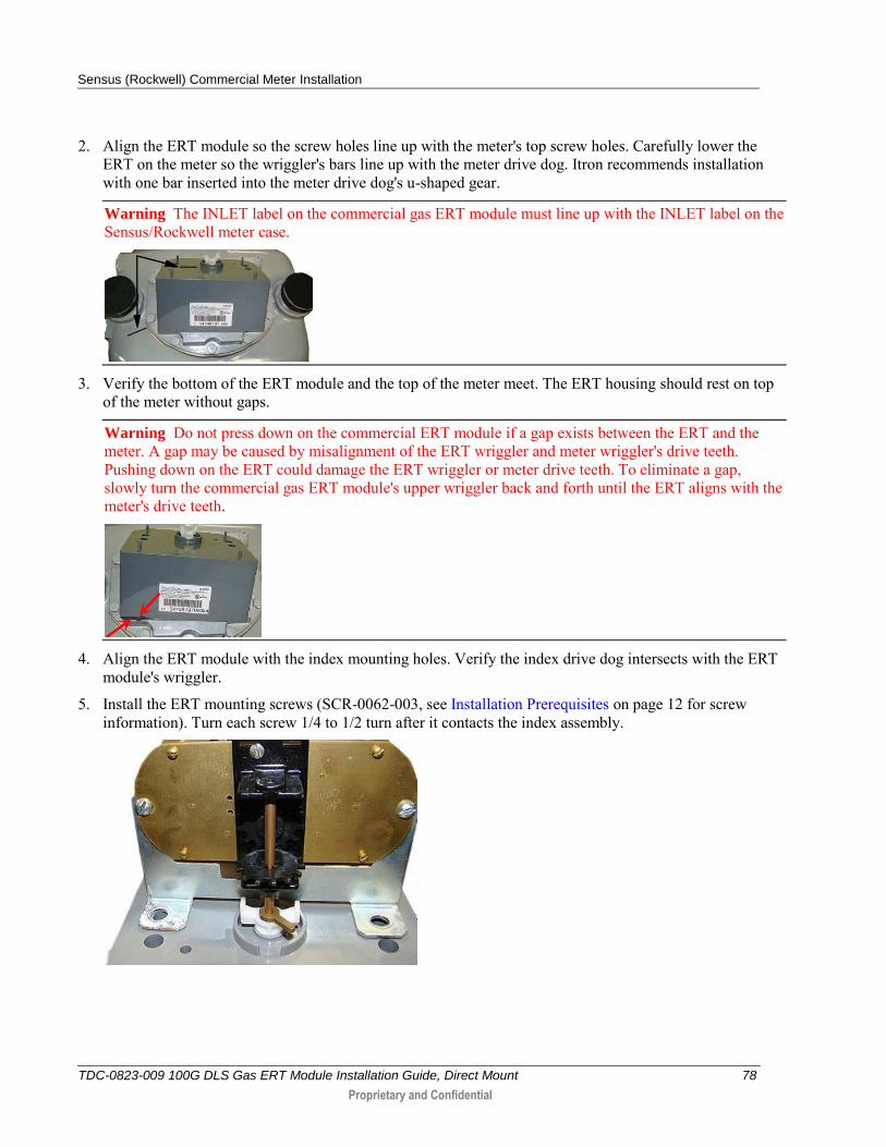
2. Align the ERT module so the screw holes line up with the meter's top screw holes. Carefully lower the ERT on the meter so the wriggler's bars line up with the meter drive dog. Itron recommends installation with one bar inserted into the meter drive dog's u-shaped gear.
Warning The INLET label on the commercial gas ERT module must line up with the INLET label on the Sensus/Rockwell meter case.
3. Verify the bottom of the ERT module and the top of the meter meet. The ERT housing should rest on top of the meter without gaps.
Warning Do not press down on the commercial ERT module if a gap exists between the ERT and the meter. A gap may be caused by misalignment of the ERT wriggler and meter wriggler's drive teeth. Pushing down on the ERT could damage the ERT wriggler or meter drive teeth. To eliminate a gap, slowly turn the commercial gas ERT module's upper wriggler back and forth until the ERT aligns with the meter's drive teeth.
4. Align the ERT module with the index mounting holes. Verify the index drive dog intersects with the ERT module's wriggler.
5. Install the ERT mounting screws (SCR-0062-003, see Installation Prerequisites on page 12 for screw information). Turn each screw 1/4 to 1/2 turn after it contacts the index assembly.
Sensus (Rockwell) Commercial Meter Installation
TDC-0823-009 100G DLS Gas ERT Module Installation Guide, Direct Mount 79
Proprietary and Confidential
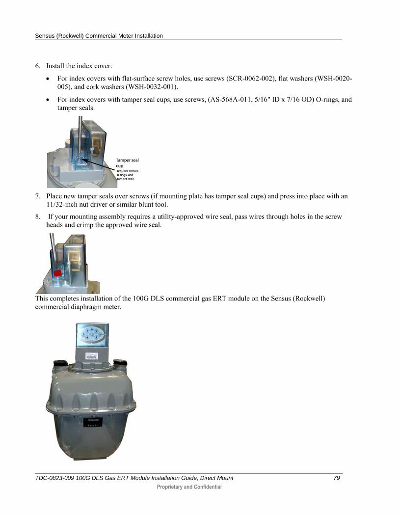
6. Install the index cover.
For index covers with flat-surface screw holes, use screws (SCR-0062-002), flat washers (WSH-0020-005), and cork washers (WSH-0032-001).
For index covers with tamper seal cups, use screws, (AS-568A-011, 5/16" ID x 7/16 OD) O-rings, and tamper seals.
7. Place new tamper seals over screws (if mounting plate has tamper seal cups) and press into place with an
11/32-inch nut driver or similar blunt tool.
8. If your mounting assembly requires a utility-approved wire seal, pass wires through holes in the screw heads and crimp the approved wire seal.
This completes installation of the 100G DLS commercial gas ERT module on the Sensus (Rockwell) commercial diaphragm meter.
Sensus (Rockwell) Commercial Meter Installation
TDC-0823-009 100G DLS Gas ERT Module Installation Guide, Direct Mount 80
Proprietary and Confidential
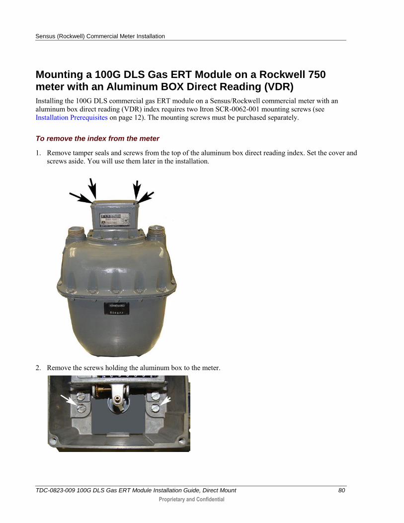
Mounting a 100G DLS Gas ERT Module on a Rockwell 750 meter with an Aluminum BOX Direct Reading (VDR)
Installing the 100G DLS commercial gas ERT module on a Sensus/Rockwell commercial meter with an aluminum box direct reading (VDR) index requires two Itron SCR-0062-001 mounting screws (see Installation Prerequisites on page 12). The mounting screws must be purchased separately.
To remove the index from the meter
1. Remove tamper seals and screws from the top of the aluminum box direct reading index. Set the cover and screws aside. You will use them later in the installation.
2. Remove the screws holding the aluminum box to the meter.
Sensus (Rockwell) Commercial Meter Installation
TDC-0823-009 100G DLS Gas ERT Module Installation Guide, Direct Mount 81
Proprietary and Confidential
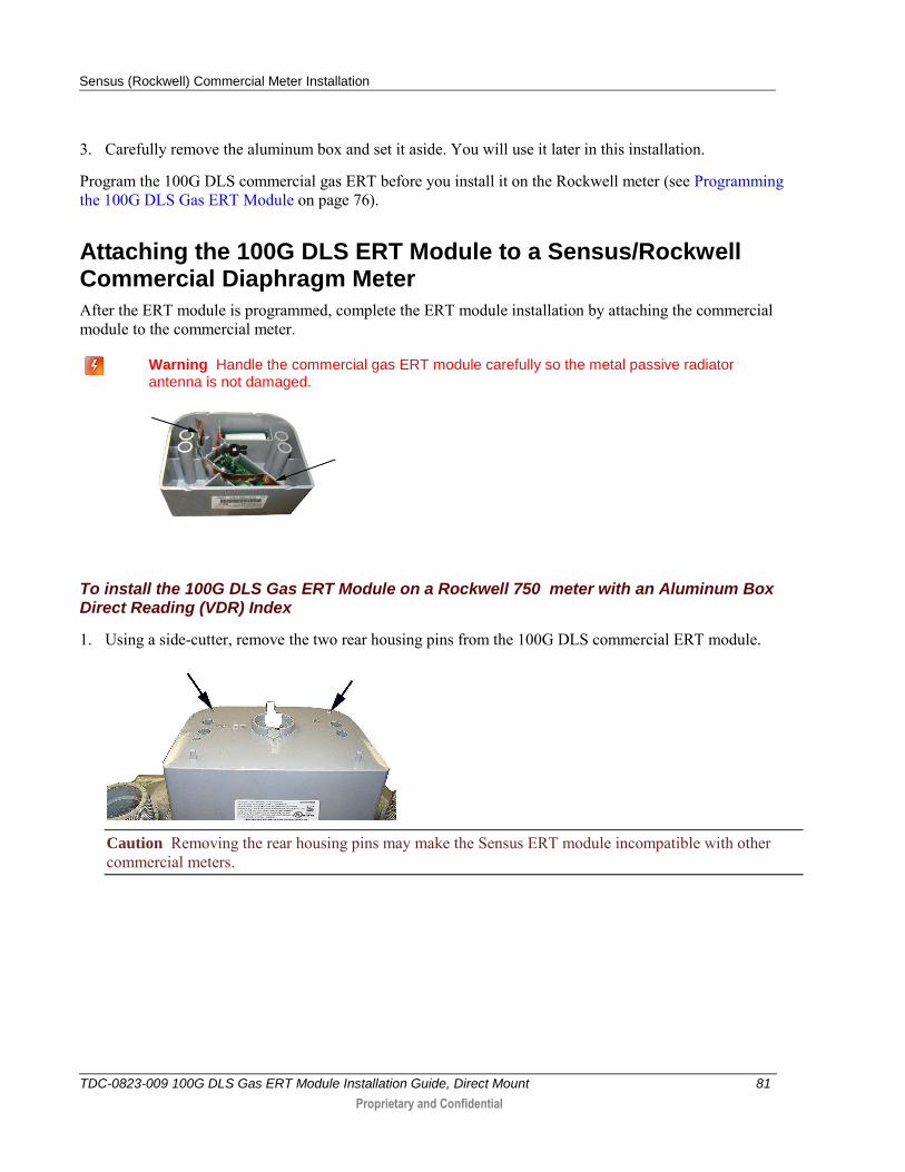
3. Carefully remove the aluminum box and set it aside. You will use it later in this installation.
Program the 100G DLS commercial gas ERT before you install it on the Rockwell meter (see Programming the 100G DLS Gas ERT Module on page 76).
Attaching the 100G DLS ERT Module to a Sensus/Rockwell Commercial Diaphragm Meter
After the ERT module is programmed, complete the ERT module installation by attaching the commercial module to the commercial meter.
Warning Handle the commercial gas ERT module carefully so the metal passive radiator antenna is not damaged.
To install the 100G DLS Gas ERT Module on a Rockwell 750 meter with an Aluminum Box Direct Reading (VDR) Index
1. Using a side-cutter, remove the two rear housing pins from the 100G DLS commercial ERT module.
Caution Removing the rear housing pins may make the Sensus ERT module incompatible with other commercial meters.
Sensus (Rockwell) Commercial Meter Installation
TDC-0823-009 100G DLS Gas ERT Module Installation Guide, Direct Mount 82
Proprietary and Confidential
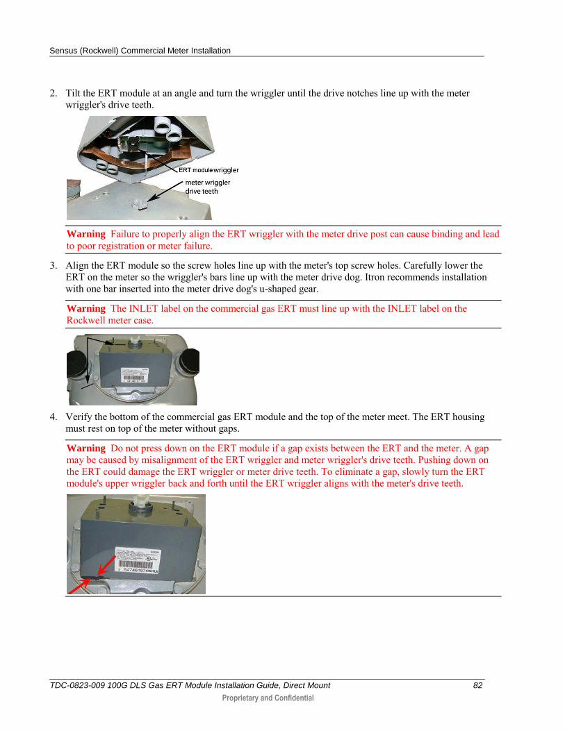
2. Tilt the ERT module at an angle and turn the wriggler until the drive notches line up with the meter wriggler's drive teeth.
Warning Failure to properly align the ERT wriggler with the meter drive post can cause binding and lead to poor registration or meter failure.
3. Align the ERT module so the screw holes line up with the meter's top screw holes. Carefully lower the ERT on the meter so the wriggler's bars line up with the meter drive dog. Itron recommends installation with one bar inserted into the meter drive dog's u-shaped gear.
Warning The INLET label on the commercial gas ERT must line up with the INLET label on the Rockwell meter case.
4. Verify the bottom of the commercial gas ERT module and the top of the meter meet. The ERT housing
must rest on top of the meter without gaps.
Warning Do not press down on the ERT module if a gap exists between the ERT and the meter. A gap may be caused by misalignment of the ERT wriggler and meter wriggler's drive teeth. Pushing down on the ERT could damage the ERT wriggler or meter drive teeth. To eliminate a gap, slowly turn the ERT module's upper wriggler back and forth until the ERT wriggler aligns with the meter's drive teeth.
Sensus (Rockwell) Commercial Meter Installation
TDC-0823-009 100G DLS Gas ERT Module Installation Guide, Direct Mount 83
Proprietary and Confidential
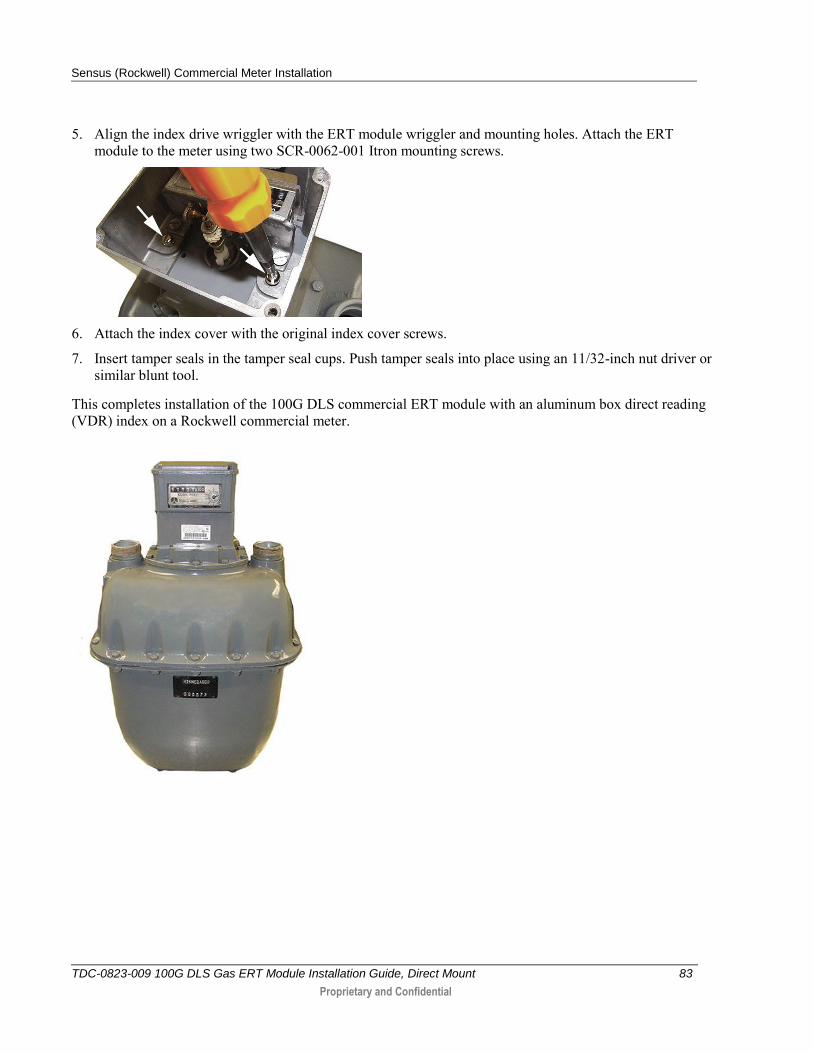
5. Align the index drive wriggler with the ERT module wriggler and mounting holes. Attach the ERT module to the meter using two SCR-0062-001 Itron mounting screws.
6. Attach the index cover with the original index cover screws.
7. Insert tamper seals in the tamper seal cups. Push tamper seals into place using an 11/32-inch nut driver or similar blunt tool.
This completes installation of the 100G DLS commercial ERT module with an aluminum box direct reading (VDR) index on a Rockwell commercial meter.
TDC-0823-009 100G DLS Gas ERT Module Installation Guide, Direct Mount 84
Proprietary and Confidential
This chapter provides the instructions to mount 100G DLS ERT modules (residential and commercial) on Dresser commercial rotary meters.
Some commercial AMR applications require a Dresser rotary meter with a residential 100G DLS. Only Elster American version residential 100G DLS ERT modules are compatible with Dresser series rotary gas meters.This chapter provides the instructions to mount an Elster American residential 100G DLS on Dresser AMR-ready rotary commercial meters. Installation requires an AMR adapter kit supplied by Dresser. Refer to the Meter Compatibility List on page 3 for Dresser AMR adapter kit part numbers.
Installation Prerequisites
Materials Supplied By Itron
100G DLS gas ERT module
New tamper seals, if applicable
Materials Supplied by You
AMR-ready Dresser Rotary Meter
Adapter Kit from Dresser
Elster American Meter index if mounting to 5C15 or 8C15 Rotary Meter
Note Follow the manufacturer field installation instructions to modify the AMR-ready Dresser Meter for 100G DLS installation. Contact a GE distributor or GE representative for installation instructions specific to the required AMR adapter kit.
C H A P T E R 8
GE Oil & Gas Dresser Commercial Rotary Meter Installation
GE Oil & Gas Dresser Commercial Rotary Meter Installation
TDC-0823-009 100G DLS Gas ERT Module Installation Guide, Direct Mount 85
Proprietary and Confidential
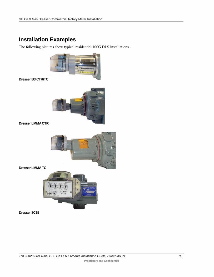
Installation Examples
The following pictures show typical residential 100G DLS installations.
Dresser B3 CTR/TC
Dresser LMMA CTR
Dresser LMMA TC
Dresser 8C15
GE Oil & Gas Dresser Commercial Rotary Meter Installation
TDC-0823-009 100G DLS Gas ERT Module Installation Guide, Direct Mount 86
Proprietary and Confidential
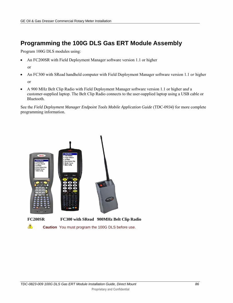
Programming the 100G DLS Gas ERT Module Assembly
Program 100G DLS modules using:
An FC200SR with Field Deployment Manager software version 1.1 or higher
or
An FC300 with SRead handheld computer with Field Deployment Manager software version 1.1 or higher
or
A 900 MHz Belt Clip Radio with Field Deployment Manager software version 1.1 or higher and a customer-supplied laptop. The Belt Clip Radio connects to the user-supplied laptop using a USB cable or Bluetooth.
See the Field Deployment Manager Endpoint Tools Mobile Application Guide (TDC-0934) for more complete programming information.
FC200SR FC300 with SRead 900MHz Belt Clip Radio
Caution You must program the 100G DLS before use.
GE Oil & Gas Dresser Commercial Rotary Meter Installation
TDC-0823-009 100G DLS Gas ERT Module Installation Guide, Direct Mount 87
Proprietary and Confidential
For 5C15 and 8C15 Rotary Meters, program as 4 dial, 2 cubic foot index. For all other residential 100G DLS gas ERT modules, refer to B3, LMMA, and S3A CTR/TC Dresser Series Register Settings and Direct Drive Programming Information on page 87.
To program the 100G DLS commercial ERT module assembly
Program the meter drive rate into the commercial ERT module using the endpoint programming device.
For all programming and Check Endpoint operations, hold the handheld programmer as close to vertical as possible. For best success, keep the handheld programmer within 6 feet of the target ERT module.
Verify you have the correct programming mode (Fixed Network Mode, Mobile/Handheld Mode, or Hard to Read Mobile/Handheld Mode) for your application. Programming parameters are based on the configuration file loaded into the endpoint programming device.
During programming, the commercial ERT module is set to the nearest 100 cubic feet; the last two digits (tens and units) are programmed as zeros (0). After programming is complete, the ERT module assembly will read to the nearest cubic foot.
GE Oil & Gas Dresser Commercial Rotary Meter Installation
TDC-0823-009 100G DLS Gas ERT Module Installation Guide, Direct Mount 88
Proprietary and Confidential
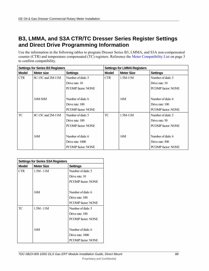
B3, LMMA, and S3A CTR/TC Dresser Series Register Settings and Direct Drive Programming Information
Use the information in the following tables to program Dresser Series B3, LMMA, and S3A non-compensated counter (CTR) and temperature compensated (TC) registers. Reference the Meter Compatibility List on page 3 to confirm compatibility.
Settings for Series B3 Registers Settings for LMMA Registers
Model Meter size Settings Model Meter Size Settings
CTR 8C-15C and 2M-11M 16M-56M
Number of dials: 5 Drive rate: 10 PCOMP factor: NONE Number of dials: 6 Drive rate: 100 PCOMP factor: NONE
CTR 1.5M-11M 16M
Number of dials: 5 Drive rate: 10 PCOMP factor: NONE Number of dials: 6 Drive rate: 100 PCOMP factor: NONE
TC 8C-15C and 2M-11M 16M
Number of dials: 5 Drive rate: 100 PCOMP factor: NONE Number of dials: 6 Drive rate: 1000 PCOMP factor: NONE
TC 1.5M-11M 16M
Number of dials: 5 Drive rate: 50 PCOMP factor: NONE Number of dials: 6 Drive rate: 500 PCOMP factor: NONE
Settings for Series S3A Registers
Model Meter Size Settings
CTR 1.5M - 11M 16M
Number of dials: 5 Drive rate: 10 PCOMP factor: NONE Number of dials: 6 Drive rate: 100 PCOMP factor: NONE
TC 1.5M - 11M 16M
Number of dials: 5 Drive rate: 100 PCOMP factor: NONE Number of dials: 6 Drive rate: 1000 PCOMP factor: NONE
GE Oil & Gas Dresser Commercial Rotary Meter Installation
TDC-0823-009 100G DLS Gas ERT Module Installation Guide, Direct Mount 89
Proprietary and Confidential
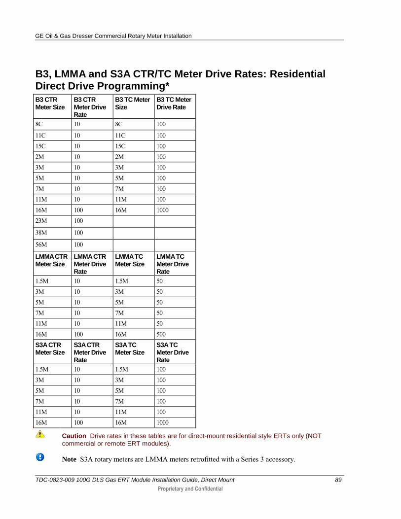
B3, LMMA and S3A CTR/TC Meter Drive Rates: Residential Direct Drive Programming*
B3 CTR Meter Size
B3 CTR Meter Drive Rate
B3 TC Meter Size
B3 TC Meter Drive Rate
8C 10 8C 100
11C 10 11C 100 15C 10 15C 100 2M 10 2M 100 3M 10 3M 100 5M 10 5M 100 7M 10 7M 100 11M 10 11M 100 16M 100 16M 1000 23M 100
38M 100
56M 100
LMMA CTR Meter Size
LMMA CTR Meter Drive Rate
LMMA TC Meter Size
LMMA TC Meter Drive Rate
1.5M 10 1.5M 50 3M 10 3M 50 5M 10 5M 50 7M 10 7M 50 11M 10 11M 50 16M 100 16M 500 S3A CTR Meter Size
S3A CTR Meter Drive Rate
S3A TC Meter Size
S3A TC Meter Drive Rate
1.5M 10 1.5M 100 3M 10 3M 100 5M 10 5M 100 7M 10 7M 100 11M 10 11M 100 16M 100 16M 1000
Caution Drive rates in these tables are for direct-mount residential style ERTs only (NOT commercial or remote ERT modules).
Note S3A rotary meters are LMMA meters retrofitted with a Series 3 accessory.
GE Oil & Gas Dresser Commercial Rotary Meter Installation
TDC-0823-009 100G DLS Gas ERT Module Installation Guide, Direct Mount 90
Proprietary and Confidential
Installing the Residential 100G DLS ERT Module Assembly to the Dresser Rotary Meter
After 100G DLS programming is complete, attach the ERT assembly to the Dresser Rotary Meter. This mounting procedure applies to B3 CTR/TC, LMMA CTR/TC, and 8C15 series Dresser Meters.
To attach the 100G DLS ERT module
Refer to the Installation Examples on page 84.
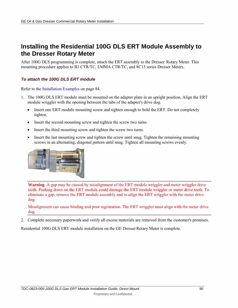
1. The 100G DLS ERT module must be mounted on the adapter plate in an upright position. Align the ERT module wriggler with the opening between the tabs of the adapter's drive dog.
Insert one ERT module mounting screw and tighten enough to hold the ERT. Do not completely tighten.
Insert the second mounting screw and tighten the screw two turns.
Insert the third mounting screw and tighten the screw two turns.
Insert the last mounting screw and tighten the screw until snug. Tighten the remaining mounting screws in an alternating, diagonal pattern until snug. Tighten all mounting screws evenly.
Warning A gap may be caused by misalignment of the ERT module wriggler and meter wriggler drive teeth. Pushing down on the ERT module could damage the ERT module wriggler or meter drive teeth. To eliminate a gap, remove the ERT module assembly and re-align the ERT wriggler with the meter drive dog.
Misalignment can cause binding and poor registration. The ERT wriggler must align with the meter drive dog.
2. Complete necessary paperwork and verify all excess materials are removed from the customer's premises.
Residential 100G DLS ERT module installation on the GE Dresser Rotary Meter is complete.
GE Oil & Gas Dresser Commercial Rotary Meter Installation
TDC-0823-009 100G DLS Gas ERT Module Installation Guide, Direct Mount 91
Proprietary and Confidential
Installing the Commercial Gas ERT on a Dresser Rotary Meter with an Instrument Drive
The information in this section guides you through the installation of the commercial gas ERT on Dresser rotary meters.
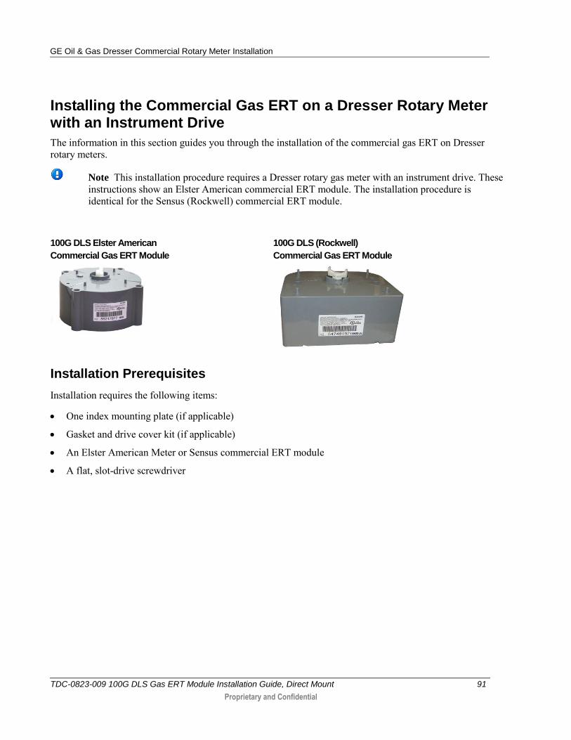
Note This installation procedure requires a Dresser rotary gas meter with an instrument drive. These instructions show an Elster American commercial ERT module. The installation procedure is identical for the Sensus (Rockwell) commercial ERT module.
100G DLS Elster American
Commercial Gas ERT Module
100G DLS (Rockwell)
Commercial Gas ERT Module
Installation Prerequisites
Installation requires the following items:
One index mounting plate (if applicable)
Gasket and drive cover kit (if applicable)
An Elster American Meter or Sensus commercial ERT module
A flat, slot-drive screwdriver
GE Oil & Gas Dresser Commercial Rotary Meter Installation
TDC-0823-009 100G DLS Gas ERT Module Installation Guide, Direct Mount 92
Proprietary and Confidential
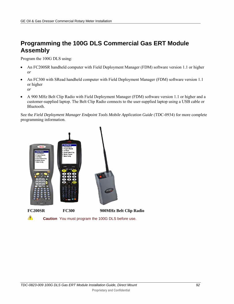
Programming the 100G DLS Commercial Gas ERT Module Assembly
Program the 100G DLS using:
An FC200SR handheld computer with Field Deployment Manager (FDM) software version 1.1 or higher or
An FC300 with SRead handheld computer with Field Deployment Manager (FDM) software version 1.1 or higher or
A 900 MHz Belt Clip Radio with Field Deployment Manager (FDM) software version 1.1 or higher and a customer-supplied laptop. The Belt Clip Radio connects to the user-supplied laptop using a USB cable or Bluetooth.
See the Field Deployment Manager Endpoint Tools Mobile Application Guide (TDC-0934) for more complete programming information.
FC200SR FC300 900MHz Belt Clip Radio
Caution You must program the 100G DLS before use.
GE Oil & Gas Dresser Commercial Rotary Meter Installation
TDC-0823-009 100G DLS Gas ERT Module Installation Guide, Direct Mount 93
Proprietary and Confidential
The ERT module is programmed based on the meter's drive rate. See B3, LMMA, and S3A CD/TD Dresser ROOTS® Series Meter Drive Rates.
To program the 100G DLS commercial ERT module assembly
Program the meter drive rate into the 100G DLS commercial gas ERT module using the endpoint programming device.
For all programming and Check Endpoint operations, hold the handheld programmer as close to vertical as possible. For best success, keep the handheld programmer within 6 feet of the target ERT module.
Verify you have the correct programming mode (Fixed Network Mode, Mobile/Handheld Mode, or Hard to Read Mobile/Handheld Mode) for your application. Programming parameters are based on the configuration file loaded into the endpoint programming device.
During programming, the 100G DLS commercial gas ERT module is set to the nearest 100 cubic feet; the last two digits (tens and units) are programmed as zeros (0). After programming is complete, the ERT module assembly will read to the nearest cubic foot.
GE Oil & Gas Dresser Commercial Rotary Meter Installation
TDC-0823-009 100G DLS Gas ERT Module Installation Guide, Direct Mount 94
Proprietary and Confidential
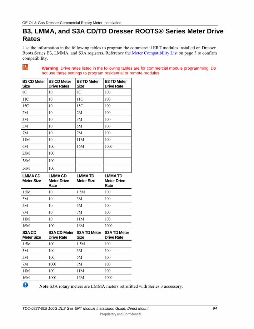
B3, LMMA, and S3A CD/TD Dresser ROOTS® Series Meter Drive Rates
Use the information in the following tables to program the commercial ERT modules installed on Dresser Roots Series B3, LMMA, and S3A registers. Reference the Meter Compatibility List on page 3 to confirm compatibility.
Warning Drive rates listed in the following tables are for commercial module programming. Do not use these settings to program residential or remote modules.
B3 CD Meter Size
B3 CD Meter Drive Rates
B3 TD Meter Size
B3 TD Meter Drive Rate
8C 10 8C 100
11C 10 11C 100 15C 10 15C 100 2M 10 2M 100 3M 10 3M 100 5M 10 5M 100 7M 10 7M 100 11M 10 11M 100 6M 100 16M 1000 23M 100
38M 100
56M 100
LMMA CD Meter Size
LMMA CD Meter Drive Rate
LMMA TD Meter Size
LMMA TD Meter Drive Rate
1.5M 10 1.5M 100 3M 10 3M 100 5M 10 5M 100 7M 10 7M 100 11M 10 11M 100 16M 100 16M 1000
S3A CD Meter Size
S3A CD Meter Drive Rate
S3A TD Meter Size
S3A TD Meter Drive Rate
1.5M 100 1.5M 100 3M 100 3M 100 5M 100 5M 100 7M 1000 7M 100 11M 100 11M 100 16M 1000 16M 1000
Note S3A rotary meters are LMMA meters retrofitted with Series 3 accessory.
GE Oil & Gas Dresser Commercial Rotary Meter Installation
TDC-0823-009 100G DLS Gas ERT Module Installation Guide, Direct Mount 95
Proprietary and Confidential
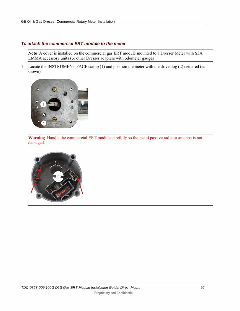
To attach the commercial ERT module to the meter
Note A cover is installed on the commercial gas ERT module mounted to a Dresser Meter with S3A LMMA accessory units (or other Dresser adapters with odometer gauges).
1. Locate the INSTRUMENT FACE stamp (1) and position the meter with the drive dog (2) centered (as shown).
Warning Handle the commercial ERT module carefully so the metal passive radiator antenna is not damaged.
GE Oil & Gas Dresser Commercial Rotary Meter Installation
TDC-0823-009 100G DLS Gas ERT Module Installation Guide, Direct Mount 96
Proprietary and Confidential
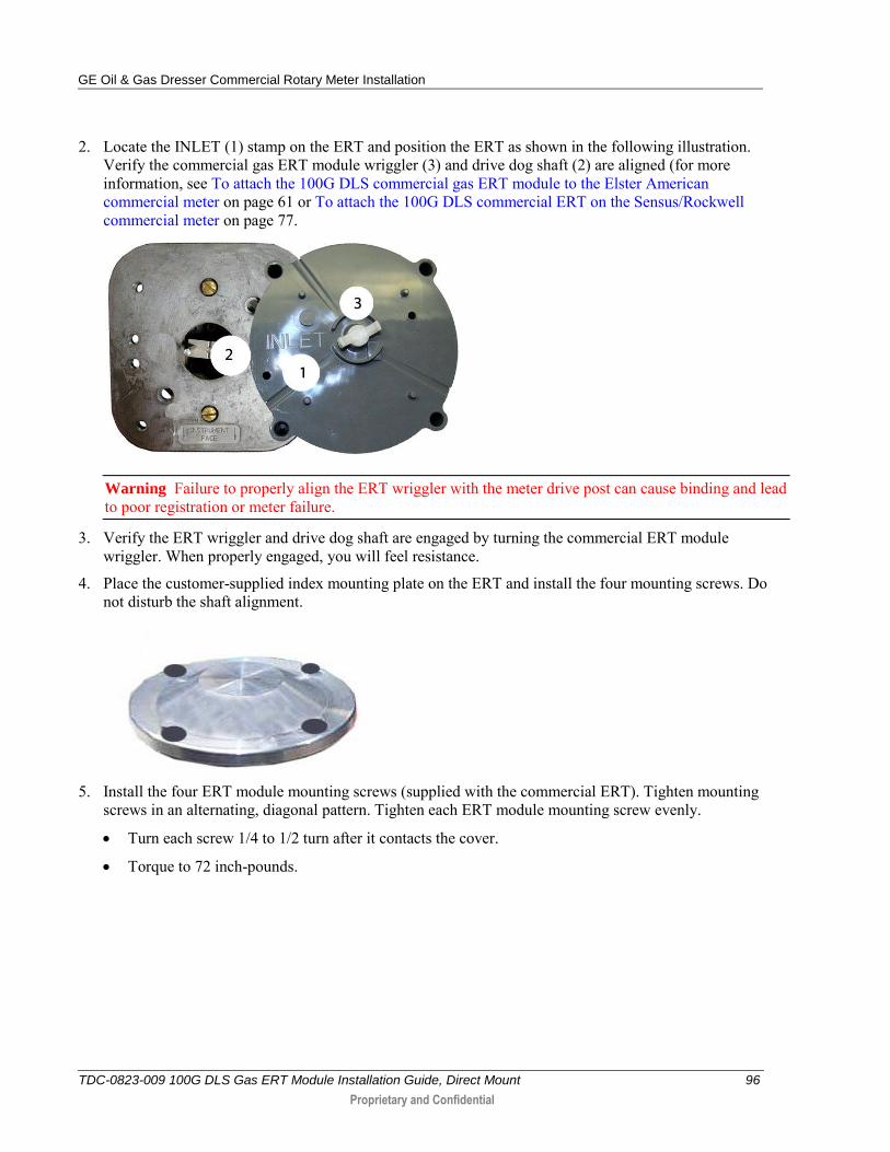
2. Locate the INLET (1) stamp on the ERT and position the ERT as shown in the following illustration. Verify the commercial gas ERT module wriggler (3) and drive dog shaft (2) are aligned (for more information, see To attach the 100G DLS commercial gas ERT module to the Elster American commercial meter on page 61 or To attach the 100G DLS commercial ERT on the Sensus/Rockwell commercial meter on page 77.
Warning Failure to properly align the ERT wriggler with the meter drive post can cause binding and lead to poor registration or meter failure.
3. Verify the ERT wriggler and drive dog shaft are engaged by turning the commercial ERT module wriggler. When properly engaged, you will feel resistance.
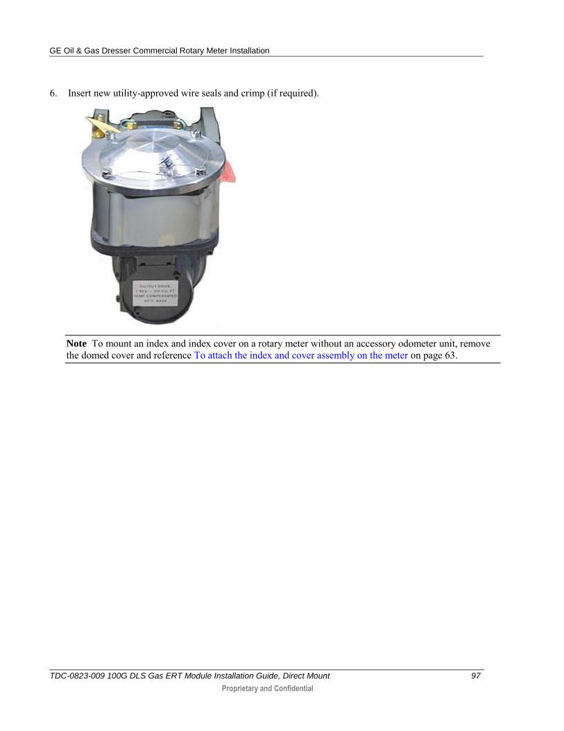
4. Place the customer-supplied index mounting plate on the ERT and install the four mounting screws. Do not disturb the shaft alignment.
5. Install the four ERT module mounting screws (supplied with the commercial ERT). Tighten mounting
screws in an alternating, diagonal pattern. Tighten each ERT module mounting screw evenly.
Turn each screw 1/4 to 1/2 turn after it contacts the cover.
Torque to 72 inch-pounds.
GE Oil & Gas Dresser Commercial Rotary Meter Installation
TDC-0823-009 100G DLS Gas ERT Module Installation Guide, Direct Mount 97
Proprietary and Confidential
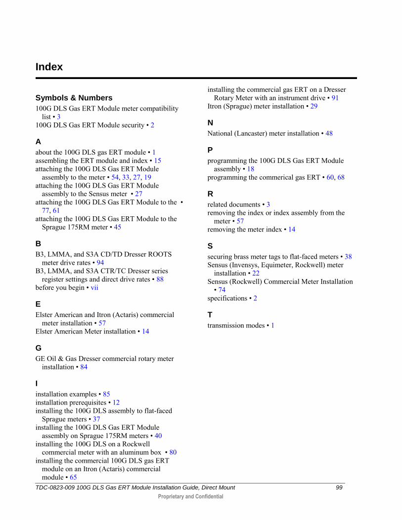
6. Insert new utility-approved wire seals and crimp (if required).
Note To mount an index and index cover on a rotary meter without an accessory odometer unit, remove the domed cover and reference To attach the index and cover assembly on the meter on page 63.

GE Oil & Gas Dresser Commercial Rotary Meter Installation
TDC-0823-009 100G DLS Gas ERT Module Installation Guide, Direct Mount 98
Proprietary and Confidential
Completed Installation Examples
100G DLS Elster American commercial gas ERT module mounted on a GE Dresser Meter with an instrument drive
100G DLS Sensus commercial gas ERT module mounted on a GE Dresser meter with an instrument drive
TDC-0823-009 100G DLS Gas ERT Module Installation Guide, Direct Mount 99
Proprietary and Confidential
Symbols & Numbers
100G DLS Gas ERT Module meter compatibility list • 3
100G DLS Gas ERT Module security • 2
A
about the 100G DLS gas ERT module • 1 assembling the ERT module and index • 15 attaching the 100G DLS Gas ERT Module
assembly to the meter • 54, 33, 27, 19 attaching the 100G DLS Gas ERT Module
assembly to the Sensus meter • 27 attaching the 100G DLS Gas ERT Module to the •
77, 61 attaching the 100G DLS Gas ERT Module to the
Sprague 175RM meter • 45
B
B3, LMMA, and S3A CD/TD Dresser ROOTS meter drive rates • 94
B3, LMMA, and S3A CTR/TC Dresser series register settings and direct drive rates • 88
before you begin • vii
E
Elster American and Itron (Actaris) commercial meter installation • 57
Elster American Meter installation • 14
G
GE Oil & Gas Dresser commercial rotary meter installation • 84
I
installation examples • 85 installation prerequisites • 12 installing the 100G DLS assembly to flat-faced
Sprague meters • 37 installing the 100G DLS Gas ERT Module
assembly on Sprague 175RM meters • 40 installing the 100G DLS on a Rockwell
commercial meter with an aluminum box • 80 installing the commercial 100G DLS gas ERT
module on an Itron (Actaris) commercial module • 65
installing the commercial gas ERT on a Dresser Rotary Meter with an instrument drive • 91
Itron (Sprague) meter installation • 29
N
National (Lancaster) meter installation • 48
P
programming the 100G DLS Gas ERT Module assembly • 18
programming the commerical gas ERT • 60, 68
R
related documents • 3 removing the index or index assembly from the
meter • 57 removing the meter index • 14
S
securing brass meter tags to flat-faced meters • 38 Sensus (Invensys, Equimeter, Rockwell) meter
installation • 22 Sensus (Rockwell) Commercial Meter Installation
• 74 specifications • 2
T
transmission modes • 1
Index