Embed Size (px)
Citation preview
ITP PRE-ASSEMBLED GAUGE PILLAR KIT (2003+ Ford 6.0L Super Duty Truck / Excursion)
INSTALLATION INSTRUCTIONS
©2004 Innovative Truck Products – All Rights Reserved – No Unauthorized Duplication Permitted Page 2 of 21
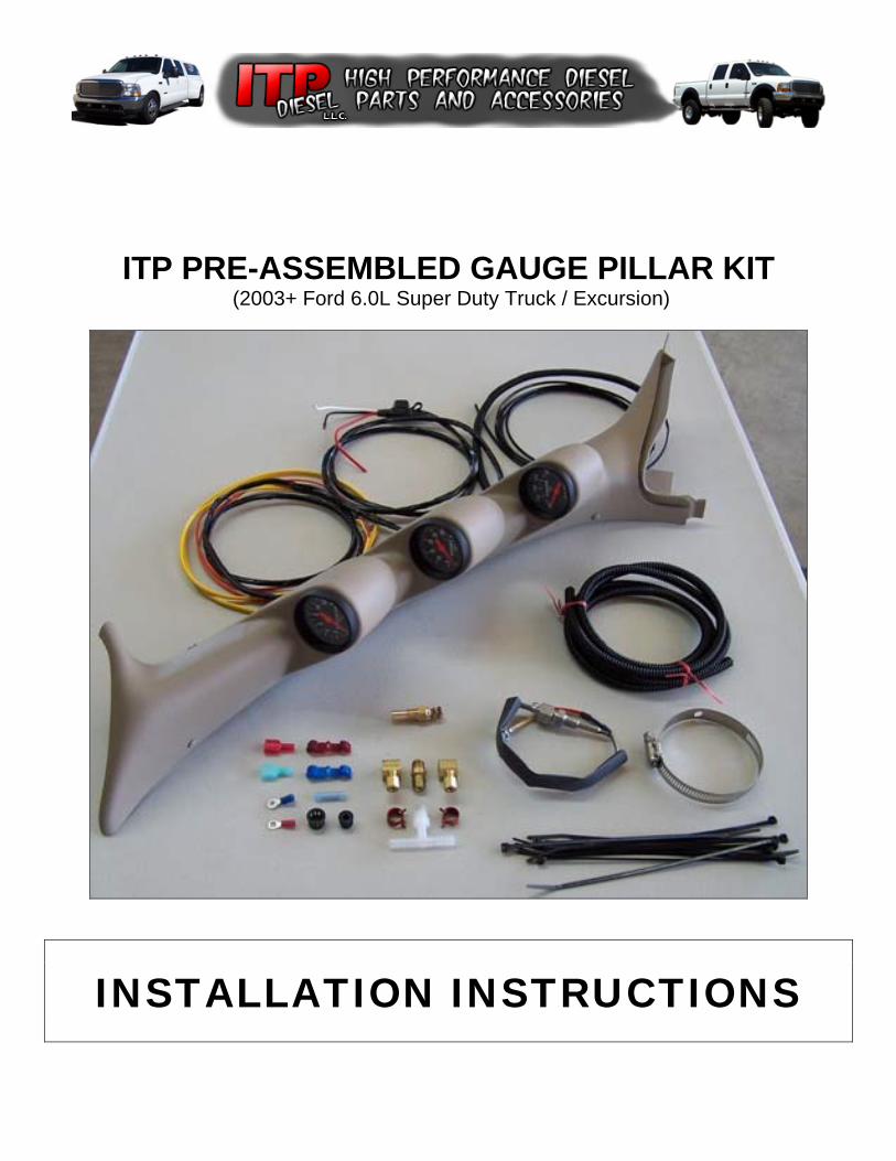
hank You for choosing the ITP PRE-ASSEMBLED GAUGE PILLAR KIT to fulfill your monitoring needs. Please take a few minutes to read over this installation guide and familiarize yourself with the components of the kit and the required tools before
starting your installation. NOTE: Don’t let the size of this guide intimidate you. We have included a TON of extra information and pictures to help installers of all skill levels… the installation is actually quite easy! It is important to note that this document is simply a “Guide” for the installation of your new Gauge Pillar Kit. While the information in this document should be accurate for a majority of 2003+ 6.0L Powerstroke Diesel Trucks and Excursions, production changes on the assembly line or the existence of other previously installed aftermarket components may require “adjustments” in the installation of this kit. We have made every attempt to make this kit as easy to install as possible. All of the wires are clearly marked and provided with more than enough length to reach their connection points. We have provided the necessary insulated electrical connectors, grommets for passing wires through the firewall, boost “T” fitting components (where applicable), wire ties, etc. We estimate that this installation should take the average home mechanic about 2 hours to complete (working at a slow and methodical pace).
SAFETY FIRST!!! Safe Work Habits help prevent unnecessary injuries.
Please pay special attention to safety notes with these symbols. If you have any questions about the installation of this kit, please feel free to call us. We would be more than happy to assist you in whatever way we can. Thank You again for your business! Sincerely, Dennis Schroeder Owner – ITPDiesel
__________________________________________________
This document covers the installation of a 2 or 3 Gauge Pillar with any combination of the following gauges:
• Exhaust Temp. (Pyrometer) Gauge • Turbo Boost Gauge • Transmission Temp. Gauge
Four (4) gauge pillars with other gauge types (i.e. Fuel Pressure, Differential Temperature, etc.) may require hardware not supplied with the ITP Kit to complete the installation. If one of these gauges is included in the pillar kit, the wiring and any additional hardware (sending units, etc.) will be appropriately marked. You may need to supply some additional hardware (fittings, hose, adapters, etc.) to complete the installation.
T
©2004 Innovative Truck Products – All Rights Reserved – No Unauthorized Duplication Permitted Page 3 of 21
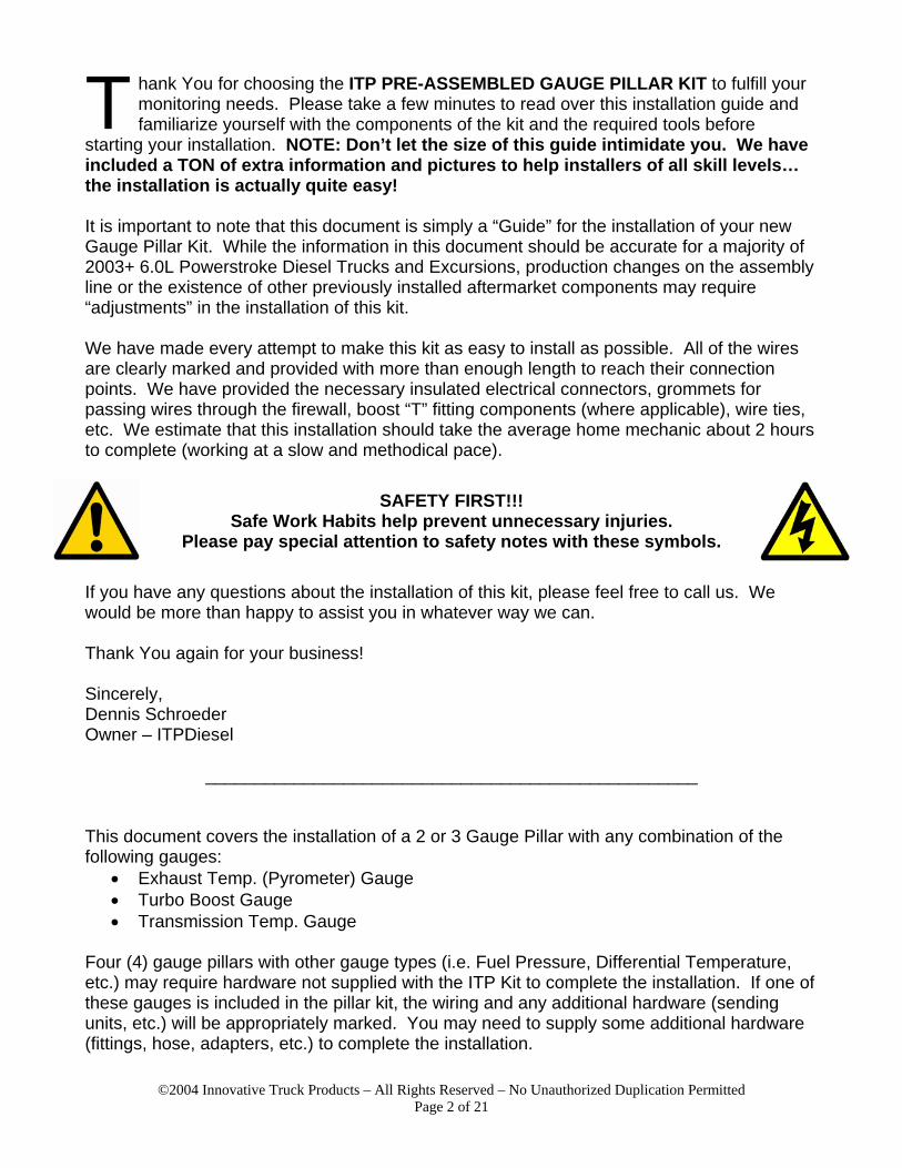
Below you will find a list of the basic hand tools that will be needed for the installation of the ITP PRE-ASSEMBLED GAUGE PILLAR KIT. Some of the items on the list are “sets” as several different sizes may be required to complete the installation. Items marked with an asterisk (*) are “nice to have” but not “required”. See Figure 1 below for a “sample” of the required tools.
• Set of SAE Wrenches • Set of Metric Wrenches • Metric Socket Set • Phillips Screwdriver • Set of Quality Drill Bits • Uni-Bit* (stepped drill bit) • 12v Test Light or Voltmeter
• Set of Nut Drivers* • Standard Pliers • Side Cutters / Wire Cutters • Wire Strippers • Insulated Connector Crimp Tool • Teflon Tape & Electrical Tape • Felt Tip Marker*
The following additional tools are needed for specific gauge installations:
Pyrometer Installation: Boost Gauge Installation: • Set of Sharp / Quality Drill
Bits up to either 21/64” or R size (needed for tap below)
• 1/8” NPT Tap
• Sears “Handi-Cut” or other Sharp blade to cut rubber hose and plastic boost line.
Figure 1
Sample of Basic Hand Tools Required for Installation.
©2004 Innovative Truck Products – All Rights Reserved – No Unauthorized Duplication Permitted Page 4 of 21
COMPONENTS OF THE KIT: Carefully review the component list below and compare it to the parts you received with your kit. Some of the components in this list are specific to a particular gauge type and will be marked as such. If you didn’t order that gauge, that component will not be included.
• (1) Gauge Pillar Assembly • (1) Temp. Probe (Pyrometer) • (1) Temp. Probe (Trans Temp) • (1) Boost “T” Hardware (Boost) • (15) Black Cable Ties • (1) Sheet Metal Screw • (1) 3/16” ID Snap Grommet • (1) 3/8” ID Snap Grommet • (1) 12’ Roll of Wire Loom
• (1) Red Wire Tap (Illumination) • (1) Blue Wire Tap (12v+) • (1) Yellow Wire Tap (12v+) • (1) Red Male Spade Connector (Illum.) • (1) Red Female Spade Connector (12v+) • (1) Blue Male Spade Connector (12v+) • (1) Blue Ring Terminal (12v-) • (1) Red #10 Ring Terminal (Trans Temp)
NOTE: We have provided extra connectors for making the 12v+ connection as we don’t know where you will decide to connect it in your vehicle. It is normal to have a few connectors left over when the installation is completed. INSTALLATION:
1. First we need to remove the stock pillar from the truck. If your truck is equipped with a drivers side grab handle, you will need to remove the small screw covers from the handle and unbolt the handle from the body of the truck using an 8mm socket and ratchet. Even after the 4 screws are removed, the handle will still be attached to the pillar.
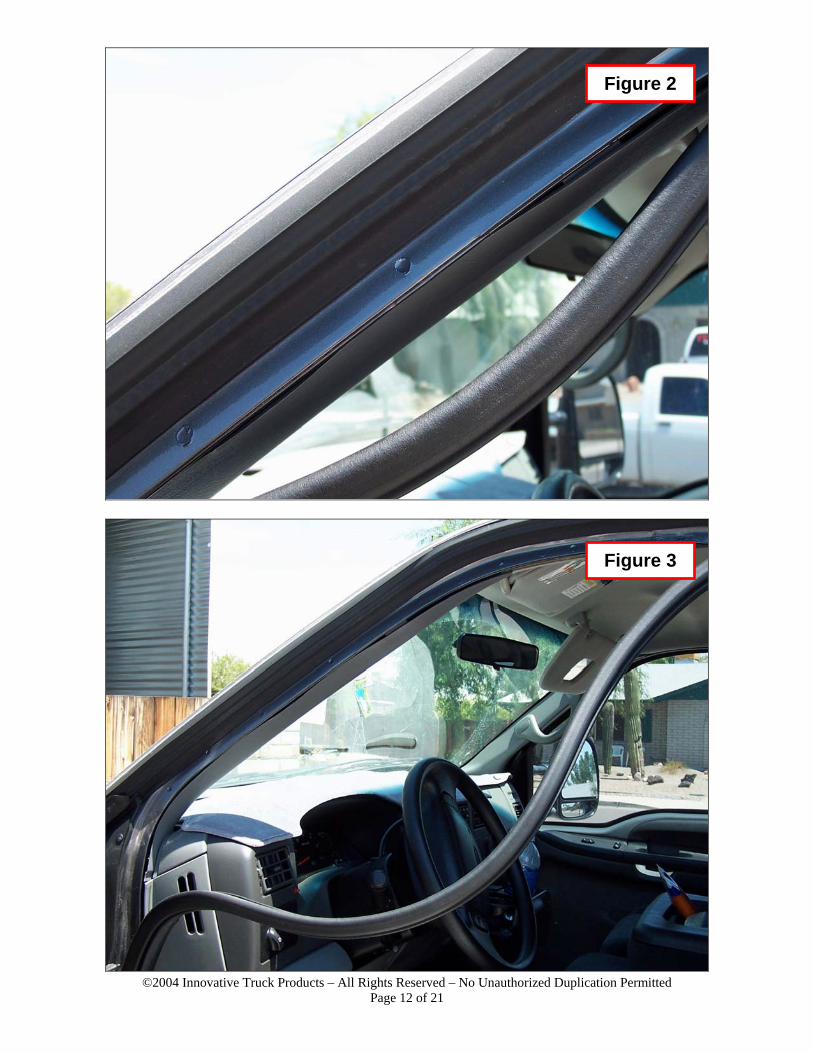
2. We now need to remove the weather-strip from the door jamb area near the pillar. The
weather-strip is not permanently attached to the truck, you simply need to grasp it and pull straight down away from the door edge (see Figures 2 and 3).
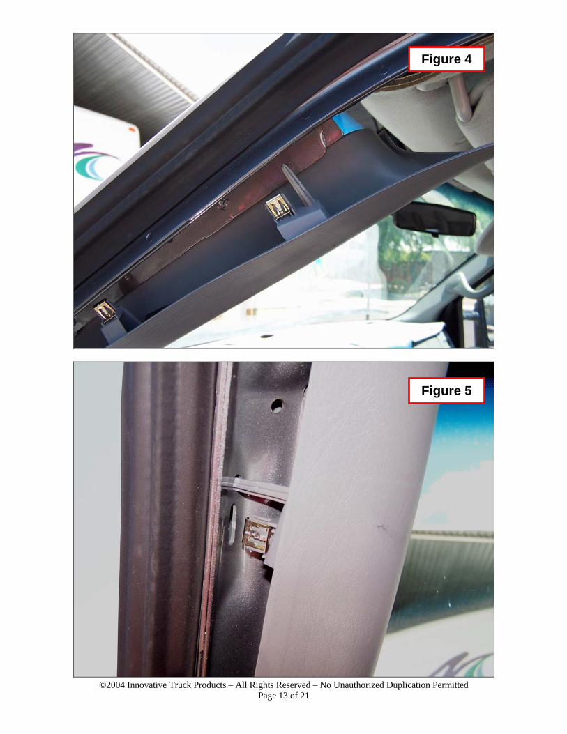
3. With the weather-strip out of the way, you can now remove the factory pillar. The factory
pillar is held in place with 3 push-in retainers (see Figures 4 & 5). Removal is simply a matter of sitting in the drivers seat, grasping the pillar at the top near the visor and pulling down and toward the drivers seat. When the 3 retainer clips have been released, the pillar can be “wiggled” out from the hole in the base of the dash (yes, it’s tight…but it will come out and the new one will go back in). Set the factory pillar (and handle if you have one) aside, they will not be needed for the installation of this kit.
• To get it out of the way, you can put the weather-strip back into place for now if
you would like.
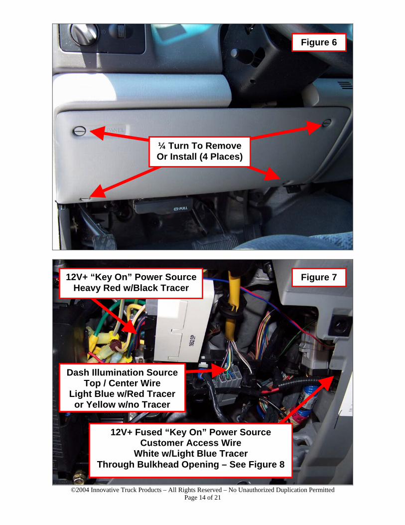
4. Now we need to remove the fuse panel cover so we have access to the wiring under the dash. Locate the fuse panel cover directly under the steering column (see Figure 6). Rotate each of the retainer screws ¼ turn counter-clockwise (they will pop out when released), remove the fuse cover and set it aside.
©2004 Innovative Truck Products – All Rights Reserved – No Unauthorized Duplication Permitted Page 5 of 21
5. Next, it’s helpful to identify the location(s) of each of the connections that will need to be
made. The following list is an example of the typical connections made during the installation of a standard 3 gauge pillar (pyrometer, boost, trans). Also listed are the wire colors for each of these connections in the ITP PRE-ASSEMBLED GAUGEL PILLAR KIT.
• 12v+ (Key-On Source) – RED • 12v- (Ground) – BLACK • 12v+ (Illumination Source) – WHITE • Temperature Probe (Pyrometer) – 2 Conductor YELLOW • Temperature Probe (Transmission) – ORANGE • Manifold Pressure (Boost) – BLACK TUBING
Use CAUTION when working with the electrical system in your truck. The use of a Test Light on the wrong wire can lead to accidental deployment of vehicle airbags and serious injury. Follow the steps below carefully and above all…BE SAFE!
6. Using Figures 7, 8 & 9 as a guide, locate a 12v+ power source for the gauges.
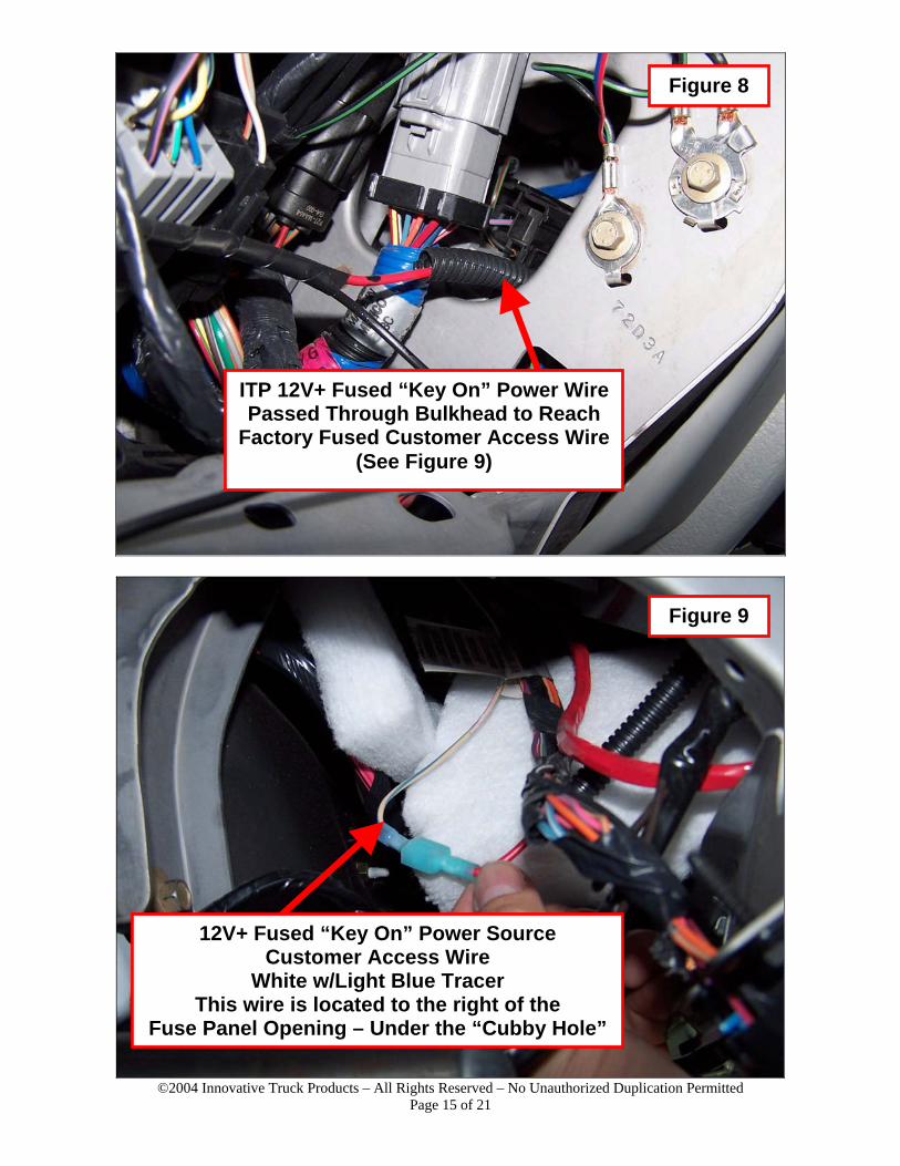
• Even though we have included an inline fuse in the wiring of our Gauge Kit, we like to use the factory fused “Customer Access” wire when it’s available. This wire will be located to the right of the bulkhead opening, under the “Cubby Hole” in the dash. The “Customer Access” wire should be WHITE W/LIGHT BLUE TRACE.
• If you would like, you can also use the HEAVY RED W/BLACK TRACE wire coming from the ignition switch bundle at the base of the steering column.
7. Using your test light or voltmeter, carefully check the wire you have chosen for 12v+ with
the key in the OFF and ON positions. 12v+ should only be present when the key is in the ON position. You can use the metal framework of the dash for the ground for your light or meter. Once you have confirmed proper operation of this circuit, mark the wire or make note of which one you will be using.
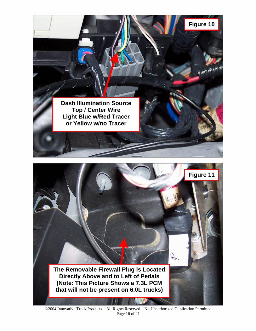
8. Using Figures 7 & 10 as a guide, locate the 12v+ Illumination source wire. Again, verify
proper function of this wire with the test light or voltmeter. This wire should go hot when the parking lights or headlights are turned on. Your test light should dim (or you should see a voltage drop on your meter) when operating the dimmer control on the factory headlight switch.
At this time we recommend that both batteries be disconnected (both positive and negative terminals) until the electrical portion of the installation has been completed.
©2004 Innovative Truck Products – All Rights Reserved – No Unauthorized Duplication Permitted Page 6 of 21
9. Install the appropriate connector on the 12v+ source that you identified in step 6.
• If you will be using the WHITE W/LIGHT BLUE TRACE “Customer Access” wire,
install a RED FEMALE SPADE CONNECTOR. Strip about ¼” of insulation from the “Customer Access” wire, twist the strands tightly and then securely crimp the connector to the “Customer Access” wire.
• If you will be using the HEAVY RED W/BLACK TRACE wire in the ignition bundle, install a YELLOW WIRE TAP CONNECTOR. Using a pair of pliers, align the metal “Fork” of the wire tap with the center of the wire and quickly and firmly snap the connector shut using the pliers.
10. Install the RED WIRE TAP CONNECTOR onto the Illumination Source Wire you
identified in step 8. Using a pair of pliers, align the metal “Fork” of the wire tap with the center of the wire and quickly and firmly snap the connector shut using the pliers.
11. Remove the Firewall Plug shown in Figure 11. If it has never been removed, it will have
an uncut section at the center of the top and bottom edges. It can usually be removed just by pulling firmly on the plug, or you can CAREFULLY use a knife to complete the cuts first.
12. With the inside plug removed, you can see the back side of the outer firewall plug shown
in Figure 12. Using a felt tip marker, trace the circular opening in the firewall on the backside of the outer plastic plug. This will aid in properly locating the holes you’ll drill in a later step.
13. It is usually easier to push the outer plug out from inside the cab than it is to try to pry it
from under the hood. Either way, remove the outer plastic firewall plug and set it aside for a later step (along with the inside firewall plug). Some newer trucks may have a “Foil-like” insulation instead of or covering the plastic plug. NOTE: This step doesn’t apply if you have a manual transmission.
14. If you are not installing a Boost Gauge, skip to step 15.
• Locate the MAP Sensor Hose shown in Figure 13. • Remove the plastic “Split Loom” covering from the hose. • Using a “Handi-Cut” (or similar), CAREFULLY cut the MAP sensor hose in the
position shown in Figure 12. NOTE: Try to position your cut so that the line coming from the “T” fitting will not come in contact with the intercooler clamps. The clamps can be loosened and rotated back if this does happen.
• Using a pair of pliers, install the spring clamps provided in the “Boost Fittings” bag on each side of the cut you just made. Slide them far enough up the hose to not interfere with the installation of the “T” fitting.
• Install the machined aluminum “T” fitting into the MAP hose with the tubing connection facing up and slightly toward the firewall.
• Using the pliers, secure the spring clamps over the ends of the rubber hose to retain the “T” fitting.
• Reinstall the plastic “Split Loom” covering on the MAP hose with the “T” fitting sticking out. We’ll connect the gauge to the “T” fitting in a later step.
©2004 Innovative Truck Products – All Rights Reserved – No Unauthorized Duplication Permitted Page 7 of 21
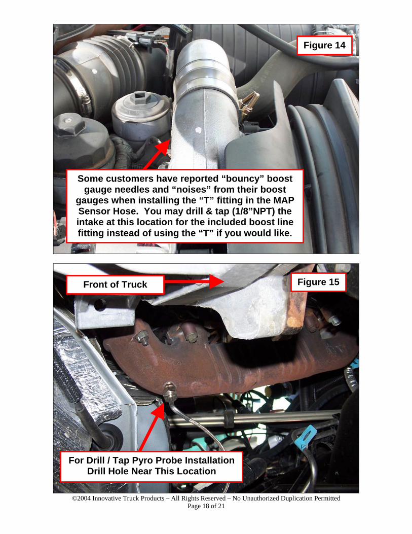
• NOTE: Some customers have reported “bouncy” gauge needles or “noisy” gauges when using the MAP Sensor Hose as the source for their boost gauge readings. See Figure 14 for an alternate location to make this connection using the supplied 1/8” NPT Brass Adapter.
• The “Intake Elbow” shown in Figure 14 will need to be removed so it can be drilled, tapped and cleaned. Please feel free to contact us if you have any questions about this procedure.
WARNING: Please wear the proper safety equipment during the following steps. Flying metal chips can cause severe eye damage and burn skin! We strongly recommend a full face shield and long sleeve shirt with tight cuffs to prevent injury!
15. If you are not installing a Pyrometer (Exhaust Temp gauge), skip to step 16.
• Using Figure 13 as a guide, locate the Drivers Side exhaust manifold. • We will be using the “Drill & Tap” method to mount the Pyrometer Probe,
carefully follow the instructions below: o Figure 15 shows the approximate location of the hole that needs to be
drilled. Your drill will only fit in this area in one position, which will determine exactly where the hole goes.
o The proper drill bit for a 1/8” NTP tap is size “R”. A 21/64” bit will also work. The use of a drill bit larger than those recommended here may result in shallow or weak threads!
o We recommend starting with your smallest bit to drill the pilot hole, then working up 1-2 bit sizes at a time until you reach the correct bit size.
o Next, tap the hole with the 1/8” NPT tap. We like to use heavy grease on the tap as it helps to capture the metal shavings as the threads are being cut. REMEMBER: You are cutting a Tapered Pipe Thread…DO NOT cut all the way to the last thread on the tap or the fitting will be too loose. Cut a few turns, remove the tap and check the fitting. If you need to cut more, clean the shavings off the tap and cut another turn or two. You want the adapter fitting to screw in about the thickness of the manifold material before it gets tight.
o After you finish tapping and checking the hole, remove the fitting and use a “Shop Vac” to remove as many chips as possible from the exhaust manifold.
o Install the adapter fitting. DO NOT overtighten!
16. If you are not installing a Transmission Temperature Gauge in an Automatic Transmission, skip to step 17.
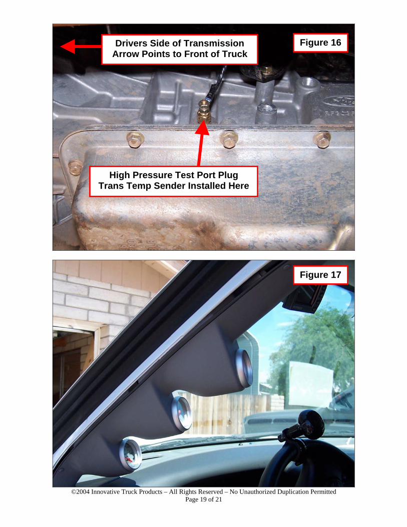
• Using Figure 16 as a guide, locate the high pressure test port plug on the drivers
side of the transmission. • Using an 11mm closed end wrench or socket, remove the plug. CAUTION:
Some transmission fluid will spill out, have a shop towel handy! • Insert the transmission temp sending unit into the test port and tighten carefully
with a 12mm wrench. DO NOT OVERTIGHTEN!
©2004 Innovative Truck Products – All Rights Reserved – No Unauthorized Duplication Permitted Page 8 of 21
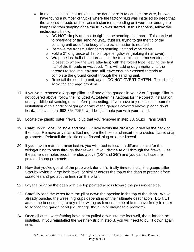
• In most cases, all that remains to be done here is to connect the wire, but we have found a number of trucks where the factory plug was installed so deep that the tapered threads of the transmission temp sending unit were not enough to keep fluid from seeping once the truck was started. If this happens, follow the instructions below:
o DO NOT simply attempt to tighten the sending unit more! This can lead to breakage of the sending unit…trust us, trying to get the tip of the sending unit out of the body of the transmission is not fun!
o Remove the transmission temp sending unit and wipe clean. o Fold a 2” long piece of Teflon Tape lengthwise (making it narrower). o Wrap the last half of the threads on the transmission temp sending unit
(closest to where the wire attaches) with the folded tape, leaving the first half of the threads unwrapped. This will add enough material to the threads to seal the leak and still leave enough exposed threads to complete the ground circuit through the sending unit.
o Reinstall the sending unit, again, DO NOT OVERTIGHTEN. This should solve the seepage problem.
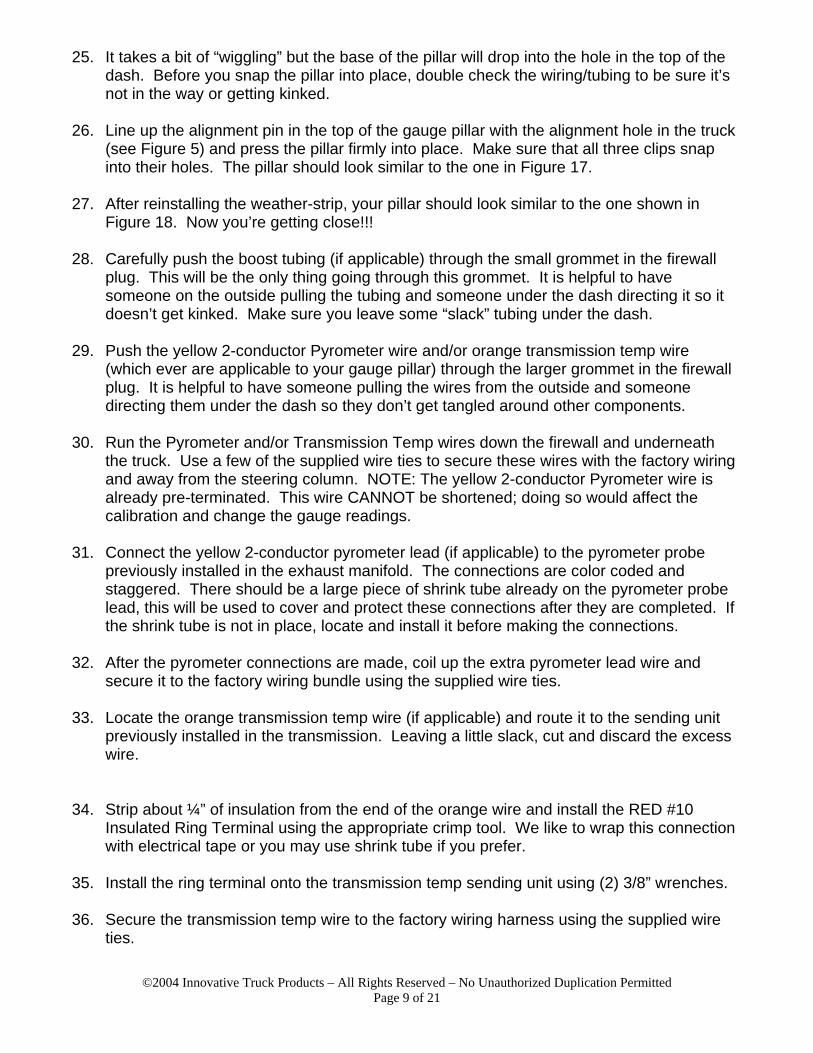
17. If you’ve purchased a 4 gauge pillar, or if one of the gauges in your 2 or 3 gauge pillar is
not covered above, follow the included AutoMeter instructions for the correct installation of any additional sending units before proceeding. If you have any questions about the installation of this additional gauge or any of the gauges covered above, please don’t hesitate to call us at 602-354-7255, we’ll be glad help you with your install.
18. Locate the plastic outer firewall plug that you removed in step 13. (Auto Trans Only)
19. Carefully drill one 1/2” hole and one 3/8” hole within the circle you drew on the back of
the plug. Remove any plastic flashing from the holes and insert the provided plastic snap grommets. Reinstall the plastic outer firewall plug onto the firewall.
20. If you have a manual transmission, you will need to locate a different place for the
wiring/tubing to pass through the firewall. If you decide to drill through the firewall, use the same size holes recommended above (1/2” and 3/8”) and you can still use the provided snap grommets.
21. Now that you’ve got all of the prep work done, it’s finally time to install the gauge pillar.
Start by laying a large bath towel or similar across the top of the dash to protect it from scratches and protect the finish on the pillar.
22. Lay the pillar on the dash with the top pointed across toward the passenger side.
23. Carefully feed the wires from the pillar down the opening in the top of the dash. We’ve
already bundled the wires in groups depending on their ultimate destination. DO NOT attach the boost tubing to any other wiring as it needs to be able to move freely in order to service the gauge head (i.e. change the bulb or diagnose a problem).
24. Once all of the wires/tubing have been pulled down into the foot well, the pillar can be
installed. If you reinstalled the weather-strip in step 3, you will need to pull it down again now.
©2004 Innovative Truck Products – All Rights Reserved – No Unauthorized Duplication Permitted Page 9 of 21
25. It takes a bit of “wiggling” but the base of the pillar will drop into the hole in the top of the dash. Before you snap the pillar into place, double check the wiring/tubing to be sure it’s not in the way or getting kinked.
26. Line up the alignment pin in the top of the gauge pillar with the alignment hole in the truck
(see Figure 5) and press the pillar firmly into place. Make sure that all three clips snap into their holes. The pillar should look similar to the one in Figure 17.
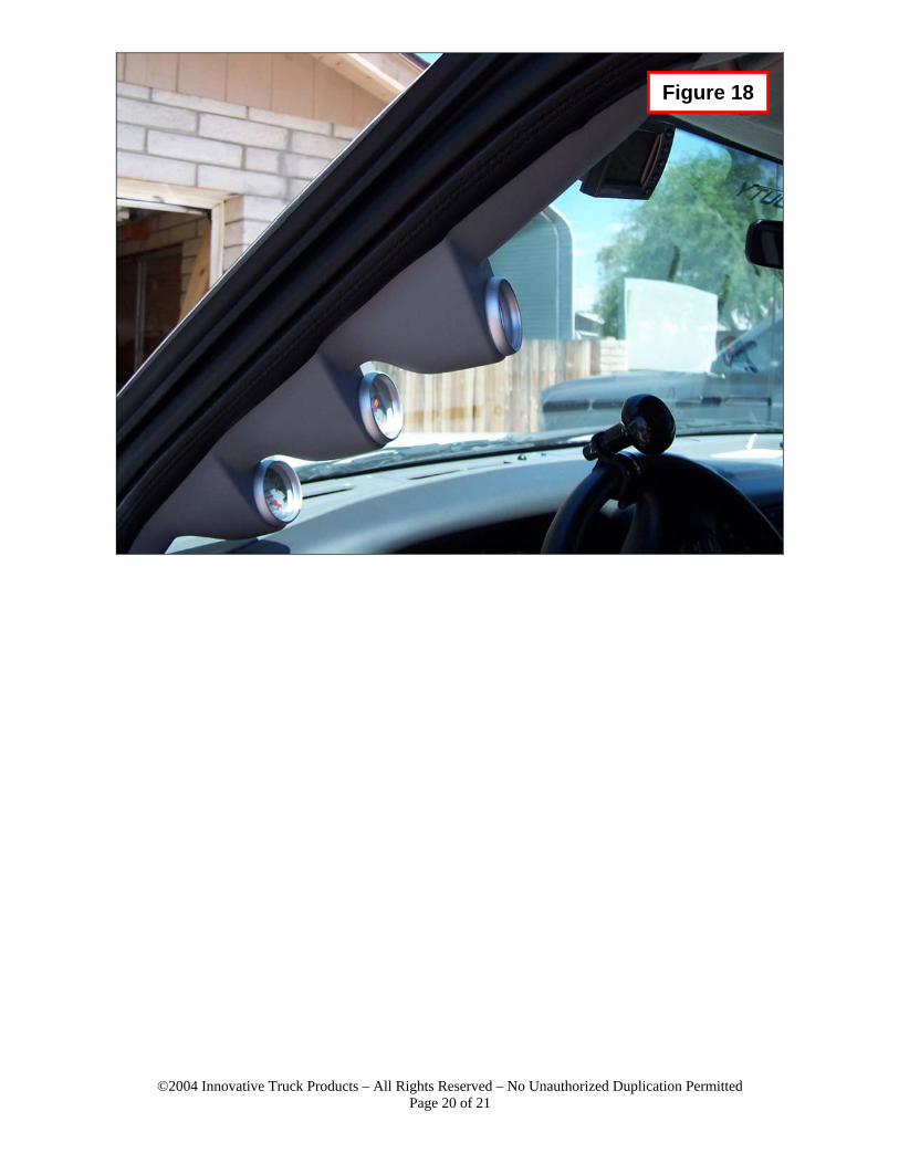
27. After reinstalling the weather-strip, your pillar should look similar to the one shown in
Figure 18. Now you’re getting close!!!
28. Carefully push the boost tubing (if applicable) through the small grommet in the firewall plug. This will be the only thing going through this grommet. It is helpful to have someone on the outside pulling the tubing and someone under the dash directing it so it doesn’t get kinked. Make sure you leave some “slack” tubing under the dash.
29. Push the yellow 2-conductor Pyrometer wire and/or orange transmission temp wire
(which ever are applicable to your gauge pillar) through the larger grommet in the firewall plug. It is helpful to have someone pulling the wires from the outside and someone directing them under the dash so they don’t get tangled around other components.
30. Run the Pyrometer and/or Transmission Temp wires down the firewall and underneath
the truck. Use a few of the supplied wire ties to secure these wires with the factory wiring and away from the steering column. NOTE: The yellow 2-conductor Pyrometer wire is already pre-terminated. This wire CANNOT be shortened; doing so would affect the calibration and change the gauge readings.
31. Connect the yellow 2-conductor pyrometer lead (if applicable) to the pyrometer probe
previously installed in the exhaust manifold. The connections are color coded and staggered. There should be a large piece of shrink tube already on the pyrometer probe lead, this will be used to cover and protect these connections after they are completed. If the shrink tube is not in place, locate and install it before making the connections.
32. After the pyrometer connections are made, coil up the extra pyrometer lead wire and
secure it to the factory wiring bundle using the supplied wire ties.
33. Locate the orange transmission temp wire (if applicable) and route it to the sending unit previously installed in the transmission. Leaving a little slack, cut and discard the excess wire.
34. Strip about ¼” of insulation from the end of the orange wire and install the RED #10 Insulated Ring Terminal using the appropriate crimp tool. We like to wrap this connection with electrical tape or you may use shrink tube if you prefer.
35. Install the ring terminal onto the transmission temp sending unit using (2) 3/8” wrenches.
36. Secure the transmission temp wire to the factory wiring harness using the supplied wire
ties.
©2004 Innovative Truck Products – All Rights Reserved – No Unauthorized Duplication Permitted Page 10 of 21
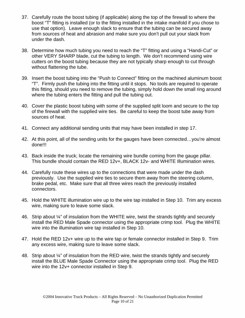
37. Carefully route the boost tubing (if applicable) along the top of the firewall to where the boost “T” fitting is installed (or to the fitting installed in the intake manifold if you chose to use that option). Leave enough slack to ensure that the tubing can be secured away from sources of heat and abrasion and make sure you don’t pull out your slack from under the dash.
38. Determine how much tubing you need to reach the “T” fitting and using a “Handi-Cut” or
other VERY SHARP blade, cut the tubing to length. We don’t recommend using wire cutters on the boost tubing because they are not typically sharp enough to cut through without flattening the tube.
39. Insert the boost tubing into the “Push to Connect” fitting on the machined aluminum boost
“T”. Firmly push the tubing into the fitting until it stops. No tools are required to operate this fitting, should you need to remove the tubing, simply hold down the small ring around where the tubing enters the fitting and pull the tubing out.
40. Cover the plastic boost tubing with some of the supplied split loom and secure to the top
of the firewall with the supplied wire ties. Be careful to keep the boost tube away from sources of heat.
41. Connect any additional sending units that may have been installed in step 17.
42. At this point, all of the sending units for the gauges have been connected…you’re almost
done!!!
43. Back inside the truck; locate the remaining wire bundle coming from the gauge pillar. This bundle should contain the RED 12v+, BLACK 12v- and WHITE Illumination wires.
44. Carefully route these wires up to the connections that were made under the dash
previously. Use the supplied wire ties to secure them away from the steering column, brake pedal, etc. Make sure that all three wires reach the previously installed connectors.
45. Hold the WHITE illumination wire up to the wire tap installed in Step 10. Trim any excess
wire, making sure to leave some slack.
46. Strip about ¼” of insulation from the WHITE wire, twist the strands tightly and securely install the RED Male Spade connector using the appropriate crimp tool. Plug the WHITE wire into the illumination wire tap installed in Step 10.
47. Hold the RED 12v+ wire up to the wire tap or female connector installed in Step 9. Trim
any excess wire, making sure to leave some slack.
48. Strip about ¼” of insulation from the RED wire, twist the strands tightly and securely install the BLUE Male Spade Connector using the appropriate crimp tool. Plug the RED wire into the 12v+ connector installed in Step 9.

©2004 Innovative Truck Products – All Rights Reserved – No Unauthorized Duplication Permitted Page 11 of 21
49. There are a few different locations to connect the BLACK 12v- (ground) wire under the dash. We have included a BLUE Insulated Ring Terminal and a Sheet Metal screw that can be used on the bottom support brace (the screw will self start with an electric screwdriver). You may choose to use one of the existing ground locations or another existing screw or nut as well. Just make sure that the location you choose is CLEAN, BARE METAL.
50. Using the supplied split loom tubing, cover any wires that could be damaged due to
abrasion or road debris (both inside and outside the cab of the truck).
51. Once all of these connections have been made (and double checked), you can reconnect the batteries (positive terminals first!).
52. Before starting the truck, turn the key to the ON position and verify that the Pyrometer
and Transmission Temp gauges (whichever are applicable) move to an appropriate temperature. These gauges will not always go to zero when the key is turned off, this is NORMAL.
53. Upon starting the truck for the first time:
• If you installed a Pyrometer, let the engine IDLE for 2-3 minutes before driving or
revving the engine. This will allow any remaining small metal chips in the exhaust manifold to pass through the exhaust side of the turbo at the slowest possible speed.
• If you installed a Transmission Temp Gauge, check for leaks at the sending unit immediately after startup. If a leak is present, turn off the truck (clean up the spill) and follow the recommendations in Step 16 to resolve the leak.
• NOTE: You will NOT see any boost pressure register on the gauge at IDLE…this is normal.
54. If all of the gauges are working properly and there are no leaks to resolve, test drive the
truck. Boost pressure will register almost immediately upon take off and exhaust temperature should rise and fall with engine load. It will take several miles of driving to see the transmission temperature change, particularly if it’s cold outside.
55. Assuming a successful test drive, reinstall the fuse panel cover under the dash and enjoy
your new gauges!
©2004 Innovative Truck Products – All Rights Reserved – No Unauthorized Duplication Permitted Page 12 of 21
Figure 2
Figure 3
©2004 Innovative Truck Products – All Rights Reserved – No Unauthorized Duplication Permitted Page 13 of 21
Figure 4
Figure 5
©2004 Innovative Truck Products – All Rights Reserved – No Unauthorized Duplication Permitted Page 14 of 21
12V+ “Key On” Power Source Heavy Red w/Black Tracer
Dash Illumination Source Top / Center Wire
Light Blue w/Red Tracer or Yellow w/no Tracer
12V+ Fused “Key On” Power Source Customer Access Wire
White w/Light Blue Tracer Through Bulkhead Opening – See Figure 8
Figure 7
Figure 6
¼ Turn To Remove Or Install (4 Places)
©2004 Innovative Truck Products – All Rights Reserved – No Unauthorized Duplication Permitted Page 15 of 21
12V+ Fused “Key On” Power Source Customer Access Wire
White w/Light Blue Tracer This wire is located to the right of the
Fuse Panel Opening – Under the “Cubby Hole”
Figure 8
Figure 9
ITP 12V+ Fused “Key On” Power Wire Passed Through Bulkhead to Reach
Factory Fused Customer Access Wire (See Figure 9)
©2004 Innovative Truck Products – All Rights Reserved – No Unauthorized Duplication Permitted Page 16 of 21
Dash Illumination Source Top / Center Wire
Light Blue w/Red Tracer or Yellow w/no Tracer
The Removable Firewall Plug is Located Directly Above and to Left of Pedals
(Note: This Picture Shows a 7.3L PCM that will not be present on 6.0L trucks)
Figure 10
Figure 11

©2004 Innovative Truck Products – All Rights Reserved – No Unauthorized Duplication Permitted Page 17 of 21
Removable Firewall Plug Located Next To Brake Master
Cylinder Toward Outside of Truck
Figure 12
Boost Gauge “T” Fitting Inserted in MAP Sensor Hose Here
(older plastic fitting shown here)
Figure 13 MAP Sensor
©2004 Innovative Truck Products – All Rights Reserved – No Unauthorized Duplication Permitted Page 18 of 21
Figure 15
For Drill / Tap Pyro Probe Installation Drill Hole Near This Location
Figure 14
Front of Truck
Some customers have reported “bouncy” boost gauge needles and “noises” from their boost
gauges when installing the “T” fitting in the MAP Sensor Hose. You may drill & tap (1/8”NPT) the intake at this location for the included boost line fitting instead of using the “T” if you would like.
©2004 Innovative Truck Products – All Rights Reserved – No Unauthorized Duplication Permitted Page 19 of 21
High Pressure Test Port Plug Trans Temp Sender Installed Here
Drivers Side of Transmission Arrow Points to Front of Truck
Figure 16
Figure 17
©2004 Innovative Truck Products – All Rights Reserved – No Unauthorized Duplication Permitted Page 20 of 21
Figure 18

©2004 Innovative Truck Products – All Rights Reserved – No Unauthorized Duplication Permitted Page 21 of 21
ITP WARRANTY AND LIABILITY POLICY
MOST OF THE PRODUCTS SOLD BY ITP DIESEL, L.L.C. ARE DESIGNED TO INCREASE VEHICLE PERFORMANCE…USE AT YOUR OWN RISK!
Do not install or use any product(s) purchased from ITP Diesel, L.L.C.
until you have carefully read the following Warranty and Liability Policy (the “Warranty”). Subject to the limitations, exclusions, and qualifications set forth below, the product or the products made and sold (the "Product" or "Products") by ITP Diesel, L.L.C (the “Seller”) and installed by the buyer (the “Buyer”) are warranted to the Buyer as set forth in this Warranty. The installation of the Products indicates that the Buyer has read, understands and agrees to the terms and conditions of this Warranty. Any warranty on products that are made by another manufacturer which are resold by the Seller to the Buyer is made to the Buyer by the manufacturer of such products in accordance with and subject to all conditions and limitations of the manufacturer's warranty in effect on the date of the purchase by the Buyer. The Seller makes no warranties to the Buyer, express or implied, with respect to such products that are made by another manufacturer. LIMITED WARRANTY The Products are warranted to be free from defects in material and workmanship, under normal use and service for a period of ninety (90) days from date of delivery to the Buyer (the “Warranty Period”). The Seller's liability under this Warranty is limited to repair or replacement at its option, subject to the provisions set forth herein, of any Products which upon examination by Seller are found to be defective. The Buyer shall prepay cost of transportation of defective Products to the Seller for inspection. The Seller shall not have any responsibility under this Warranty unless the defect in a Product results in a claim arising within ninety (90) days from the date of delivery to the Buyer, the Product was properly installed, normally maintained and not subject to misuse, negligence or accident, and the Product, system components and/or accessories were not repaired or altered in such a way that in the judgment of the Seller the Product’s performance or reliability was adversely affected. EXCLUSIONS Any of the above warranties by the Seller shall not apply if the Buyer’s vehicle is in an accident, misused, neglected, altered from the Product’s manufacturer original designs or specifications or serviced in connection with a warranty claim hereunder without prior written approval of the Seller. REMEDIES EXCLUSIVE Repair or replacement of defective Products in accordance with the Limited Warranty above shall be the Buyer’s exclusive remedy for and shall constitute satisfaction of any and all liabilities of the Seller with respect to any defect in any Product whether based in warranty, contract, tort, negligence, strict liability or otherwise. DISCLAIMERS AND LIMITATIONS The express warranties set forth above are exclusive and in lieu of all other warranties, conditions and terms as to quality or fitness of all Products supplied by the Seller to the Buyer, whether written, oral or implied, statutory or otherwise, including without limitation, any warranties or conditions of merchantability or fitness for a particular purpose, and all such other warranties, conditions and terms are hereby disclaimed and excluded by the Seller. In no event shall the Seller be liable for any loss of actual or anticipated profits, loss of anticipated business, cost of substitute products, loss of use or downtime costs or delay claims (whether direct or indirect) nor for any other special, indirect, incidental or consequential damages arising out of or relating to this Warranty or the supply of Products to the Buyer, whether based in warranty, contract, tort, negligence, strict liability or otherwise. No employee or representative of the Seller has the authority to make any representation, promise or agreement which in any way varies from the terms and conditions of this Warranty. No suit or claim based on any cause of action, regardless of form, arising out of or relating to this Warranty or any of the Products supplied by the Seller may be brought by the Buyer or anyone claiming by, through or under the Buyer against the Seller more than one year after the date that such cause of action arose. ASSIGNABILITY OF WARRANTY This Warranty is for the exclusive benefit of the Buyer and is not assignable. WARRANTY CLAIMS PROCEDURE Warranty claim forms can be printed from the company website (http://www.itpdiesel.com). A properly completed warranty claim form and a copy of the invoice for any defective Product must be received by the Seller within the earlier of 30 days after the expiration of the Warranty Period or the incident giving rise to the claim. To qualify for an adjustment under this Warranty the defective Product must be returned prepaid to the Seller for inspection and must be accompanied by a dated proof of purchase receipt. In addition, the serial number of the defective Product, if any, must match the serial number on the Buyer’s invoice. All Warranty claims are subject to approval by the Seller and/or the Product’s manufacturer. The Buyer must pay all applicable service charges and taxes. Defective Products accepted for warranty compensation become the property of the Seller. APPLICABLE LAW The Warranty shall be governed by the laws of the State of Arizona (excluding Arizona law with respect to conflicts of law). IN THE EVENT THE BUYER DOES NOT AGREE WITH THE TERMS AND CONDITIONS OF THIS WARRANTY, THE BUYER MAY PROMPTLY RETURN THE PRODUCT TO THE SELLERFOR A FULL REFUND. THE PRODUCT MUST BE IN NEW, UNUSED AND RESELLABLE CONDITION, BE RECEIVED WITHIN FIFTEEN (15) DAYS OF THE ORIGINAL PURCHASE AND BE ACCOMPANIED BY A DATED PROOF OF PURCHASE (RECEIPT). PRODUCTS RETURNED IN NEW, UNUSED AND RESELLABLE CONDITION WILL NOT BE SUBJECT TO ANY RESTOCKING FEES. THE INSTALLATION OR USE OF ANY PRODUCT PURCHASED FROM ITP DIESEL, L.L.C. INDICATES THAT THE BUYER HAS READ, UNDERSTANDS AND AGREES TO THE TERMS AND CONDITIONS OF THIS WARRANTY.