Embed Size (px)
Citation preview

Iterative Learning Control of a MarineVibrator
Bo Bernhardsson, Olof SörnmoLundUniversity, Olle Kröling,Per GunnarssonSubvision, Rune Tengham PGS
:
Marine Seismic Surveys
:

Outline
1 Seismic surveying
2 Acoustic Sources
3 System Identification
4 ILC
5 Results for different sensors
:

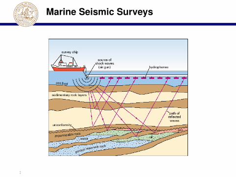
Seismic surveying
How to do seismic surveying:
Generate a HUGE acoustic signalPick up echoes using a HUGE (kilometers) sensor arrayDo some signal processing (correlation analysis)
:

Marine Seismic Surveys
:

Output from seismic survey
Higher frequencies -> Great resolution near surface structure
Lower frequency -> Better characterization of structure at depth:

Spectrum Requirements
Want to minimize impact onendangered marine speciescommercial fishing
Promote greener alternatives
Reduce high-frequency spectral contents of acoustic signal
Example of specification: Harmonics above 100 Hz should beattenuated 40 dB
:

Acoustic Sources
Air guns have traditionally dominated the market
Higher peak pressures than most other man-made sources,except explosives
New novel constructions have the potential for reduced"acoustic footprints"
:

Reduce peak pressures
Chirp signals give smaller peak pressures than airguns
:

:
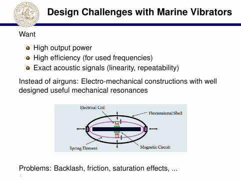
Design Challenges with Marine Vibrators
Want
High output powerHigh efficiency (for used frequencies)Exact acoustic signals (linearity, repeatability)
Instead of airguns: Electro-mechanical constructions with welldesigned useful mechanical resonances
Problems: Backlash, friction, saturation effects, ...:

The Control Problem
Input:
Voltage or current to coils
Possible measurement sensors:
Accelerometer(s) on shell of vibratorAcceleromoter(s) on moving parts inside vibratorMicrophones inside vibrator
:

Repeatable imperfections
Experiments indicate that the imperfections generate veryrepeatable errors
Good candidate for iterative learning control (ILC)
Very satisfactory results with ILC
:

Before ILC
0.8 0.81 0.82 0.83 0.84 0.85 0.86 0.87 0.88 0.89 0.9
−0.4
−0.2
0
0.2
0.4
Time [s]
Input signal before ILC
0.8 0.81 0.82 0.83 0.84 0.85 0.86 0.87 0.88 0.89 0.9−0.3
−0.2
−0.1
0
0.1
0.2
0.3
Time [s]
Output signal before ILC
:

After ILC
0.8 0.81 0.82 0.83 0.84 0.85 0.86 0.87 0.88 0.89 0.9
−0.4
−0.2
0
0.2
0.4
Time [s]
Input signal after ILC
0.8 0.81 0.82 0.83 0.84 0.85 0.86 0.87 0.88 0.89 0.9−0.3
−0.2
−0.1
0
0.1
0.2
0.3
Time [s]
Output signal after ILC
:

System identification
Dynamics can vary due to aging, temperature etc
Want to minimize time for calibration/system identification
Both SISO and MIMO operation is feasible
:

System identification
Small-signal response around nominal trajectory
Excitation signal
u(t) = u0(t) + C sin 2π fkt
for fk = [20, 1000] Hz.
Important to use a nonzero u0(t) to overcome friction etc
Two separate inputs to coils. Several sensors can be used.
SISO vs MIMO models. Choose 2$ 2 model[G11 G12G21 G22
]
:

Result, 2$ 2 MIMO, shell sensors
0 100 200 300 400 500 600 700−70
−60
−50
−40
−30
−20
−10
0
frequency [Hz]
Am
plit
ud
e [
dB
]
G11
G21
G12
G22
0 100 200 300 400 500 600 700−3000
−2500
−2000
−1500
−1000
−500
0
frequency [Hz]phase [deg]
G11
G21
G12
G22
Many resonances. Very high system order.
Decided to do ILC in the frequency domain
:
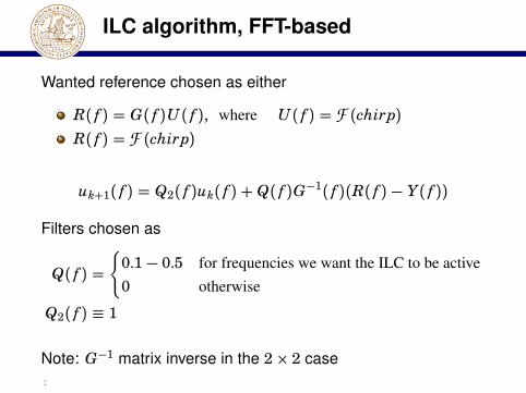
ILC algorithm, FFT-based
Wanted reference chosen as either
R( f ) = G( f )U( f ), where U( f ) = F (chirp)R( f ) = F (chirp)
uk+1( f ) = Q2( f )uk( f ) + Q( f )G−1( f )(R( f ) − Y( f ))
Filters chosen as
Q( f ) ={0.1− 0.5 for frequencies we want the ILC to be active0 otherwise
Q2( f ) " 1
Note: G−1 matrix inverse in the 2$ 2 case:

Convergence SISO
:

Robustness experiment - abrupt gainchange
0 5 10 15 20 25 30 35 40 45 500
2,000
4,000
6,000
8,000
Iteration index
Sum(abs(error))
Gain change at iteration 16
Convergence in 15 iterations
:

Spectrum after ILC - spring sensor
ILC active to 1kHz
43-60dB suppression of harmonics
:

Error Spectrum SISO
Active ILC in 30-1000Hz, Q=0.3 15 iterations, Q=0.15, 30iterations
40dB improvement in error spectrum:
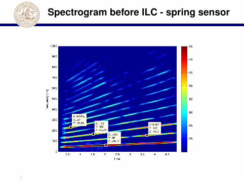
Spectrogram before ILC - spring sensor
:

Spectrogram after ILC - spring sensor
:
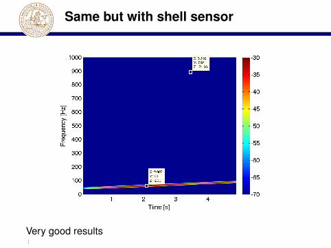
Same but with shell sensor
Very good results:

Detailed view
Detailed view, rescaled color range: 70dB.
:

A Setback
When measuring the spectrum on the side without ILC sensor itwas found that the spectrum had NOT improved very much onthat side !
:

Double-sided control
Idea: Make both sides move sinusoidally, use separate controlof the two springs
MIMO control needed
:
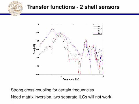
Transfer functions - 2 shell sensors
Strong cross-coupling for certain frequencies
Need matrix inversion, two separate ILCs will not work:

Spectrograms after ILC - double shellsensor
Output spectra on the shells (ILC active in [30,650] Hz)
>40dB suppression
Note: Reference = constant amplitude chirp:

Spectrograms after ILC - double shellsensor
Spectrum on the accelerometers on the two sides
Both sides move according to wanted reference
40dB suppression:
Convergence - double shell sensors
:

Convergence - double shell sensors
:

Spectrogram - double shell sensors(50dB range!)
:
Adaptation and robustifications
Several patent applications on adaptation and robustifications
Will not talk about this
:

Summary
Spectrum requirements on marine vibrators motivate novelconstructions and use of controlExperiments with ILC show promising resultsGood mechanical design is still crucial
Future workFurther testing in water is neededFurther optimization might improve the results
:

Summary
Thanks to Rune Tengham at PGS for background material
Thanks to Olle Kröling and Per Gunnarsson at Subvision AB
PGS or Subvision are not responsible for any statement oropinion expressed in this presentation
: