Embed Size (px)
DESCRIPTION
ITER Project Status. “preparing for an efficient start of ITER construction”. Ned Sauthoff Project Manager U.S. ITER Project Office FESAC 7/27/04. Scope of the ITER Transitional Arrangements*. - PowerPoint PPT Presentation
Citation preview
ITER Project Status
Ned Sauthoff
Project Manager
U.S. ITER Project Office
FESAC
7/27/04
“preparing for an efficient start of ITER construction”
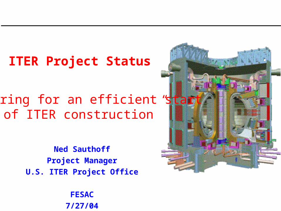
Scope of the ITER Transitional Arrangements*
• “Joint technical preparations directed at maintaining the coherence and integrity of the ITER design and at preparing for an efficient start of ITER construction”
• “Organisational preparations directed at enabling the ITER Legal Entity to enter into effective operation with least possible delay following the entry into force of the ITER Joint Implementation Agreement”
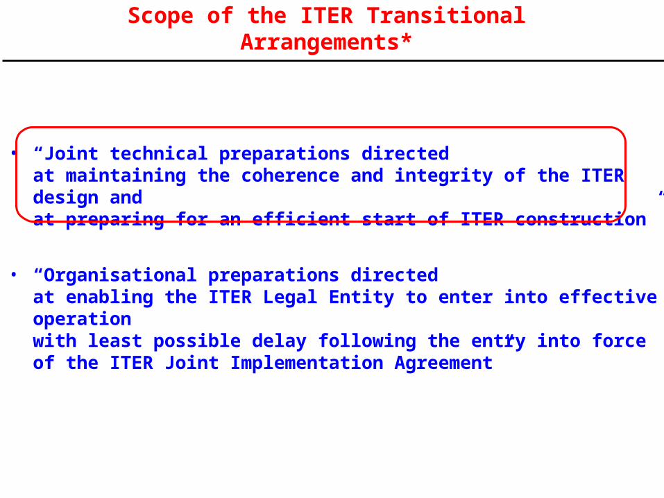
US In-kind Contributions to ITER
44% of antenna + all transmission lines,RF-sources, and power supplies
Start-up gyrotrons, all transmission lines and power supplies
15% of port-based diagnostic packages
4 of 7 Central Solenoid Modules
Steady-state power supplies
Cooling for divertor, vacuum vessel, …
Baffle
pellet injector
Tokamak exhaust processing system
Roughing pumps, standard components
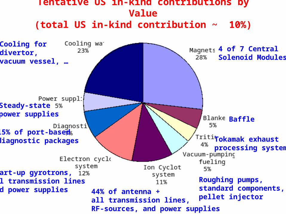
Tentative US in-kind contributions by Value(total US in-kind contribution ~ 10%)
4 of 7 Central Solenoid Modules
Tokamak exhaust processing system
Roughing pumps, standard components, pellet injector
44% of antenna + all transmission lines,RF-sources, and power supplies
Start-up gyrotrons, all transmission lines and power supplies
15% of port-based diagnostic packages
Steady-state power supplies
Cooling for divertor, vacuum vessel, …
Baffle
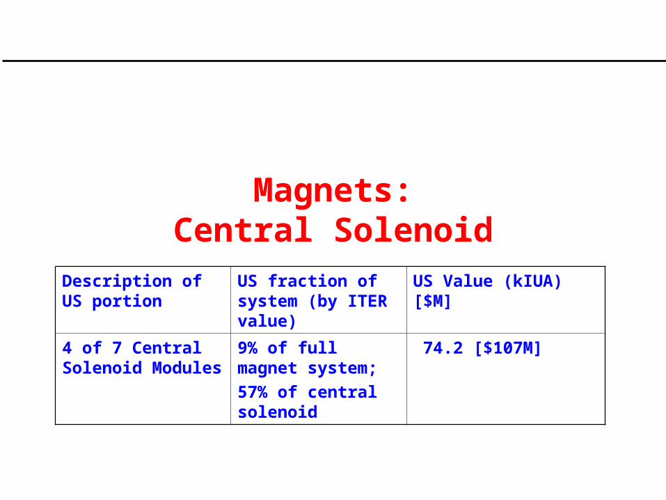
Magnets:Central Solenoid
Description of US portion
US fraction of system (by ITER value)
US Value (kIUA) [$M]
4 of 7 Central Solenoid Modules
9% of full magnet system;
57% of central solenoid
74.2 [$107M]
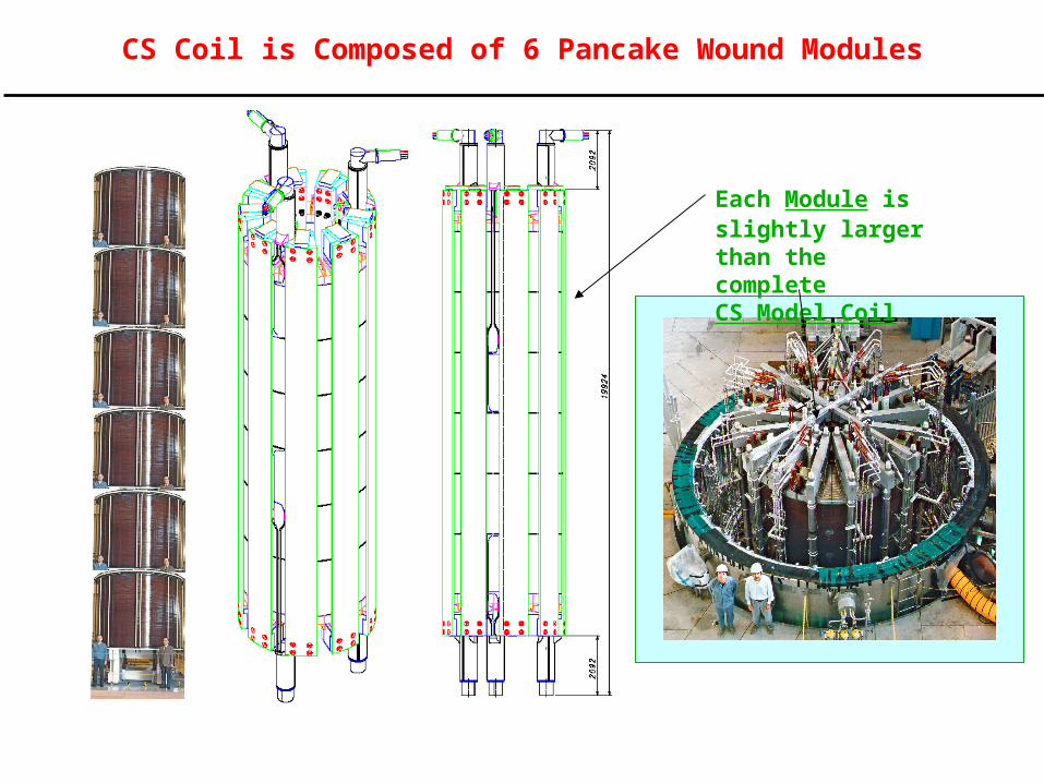
CS Coil is Composed of 6 Pancake Wound Modules
Each Module is slightly larger than the complete CS Model Coil
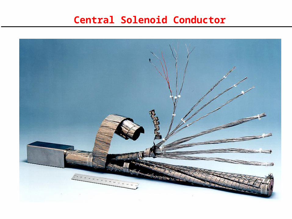
Central Solenoid Conductor
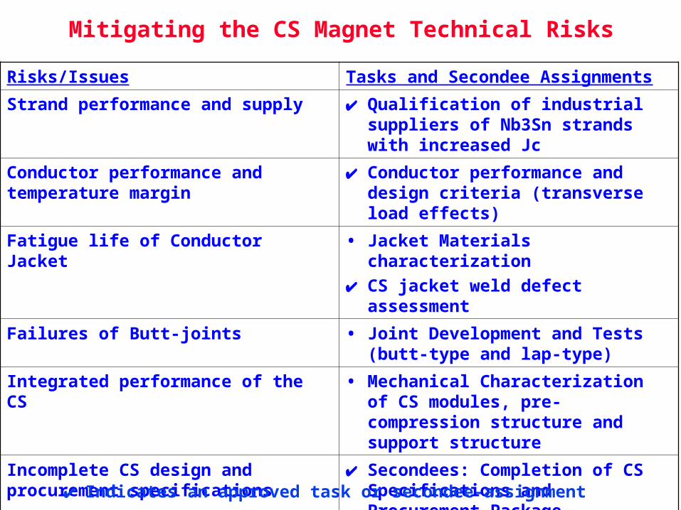
Mitigating the CS Magnet Technical Risks
Risks/Issues Tasks and Secondee Assignments
Strand performance and supply Qualification of industrial suppliers of Nb3Sn strands with increased Jc
Conductor performance and temperature margin
Conductor performance and design criteria (transverse load effects)
Fatigue life of Conductor Jacket • Jacket Materials characterization
CS jacket weld defect assessment
Failures of Butt-joints • Joint Development and Tests (butt-type and lap-type)
Integrated performance of the CS • Mechanical Characterization of CS modules, pre-compression structure and support structure
Incomplete CS design and procurement specifications
Secondees: Completion of CS Specifications and Procurement Package
Stresses in the high-field regions of CS Modules
Stress analysis of the helium inlet regions
Indicates an approved task or secondee-assignment
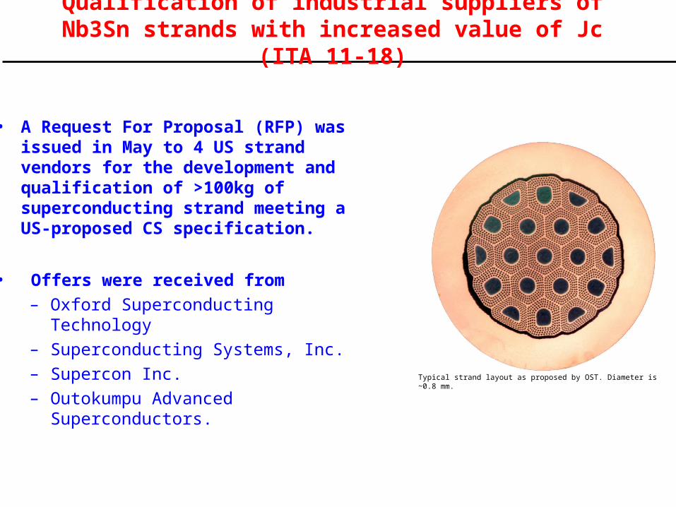
Typical strand layout as proposed by OST. Diameter is ~0.8 mm.
Qualification of industrial suppliers of Nb3Sn strands with increased value of Jc (ITA 11-18)
• A Request For Proposal (RFP) was issued in May to 4 US strand vendors for the development and qualification of >100kg of superconducting strand meeting a US-proposed CS specification.
• Offers were received from
– Oxford Superconducting Technology
– Superconducting Systems, Inc.
– Supercon Inc.
– Outokumpu Advanced Superconductors.
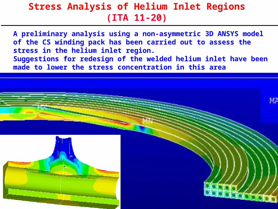
Stress Analysis of Helium Inlet Regions (ITA 11-20)
A preliminary analysis using a non-asymmetric 3D ANSYS model of the CS winding pack has been carried out to assess the stress in the helium inlet region. Suggestions for redesign of the welded helium inlet have been made to lower the stress concentration in this area
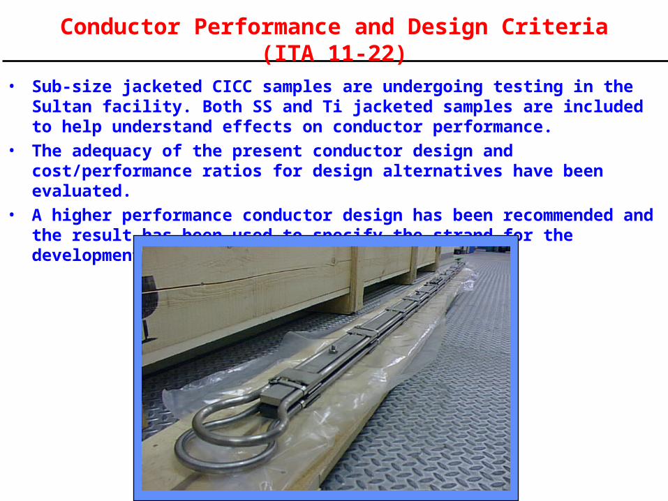
Conductor Performance and Design Criteria (ITA 11-22)
• Sub-size jacketed CICC samples are undergoing testing in the Sultan facility. Both SS and Ti jacketed samples are included to help understand effects on conductor performance.
• The adequacy of the present conductor design and cost/performance ratios for design alternatives have been evaluated.
• A higher performance conductor design has been recommended and the result has been used to specify the strand for the development contracts.
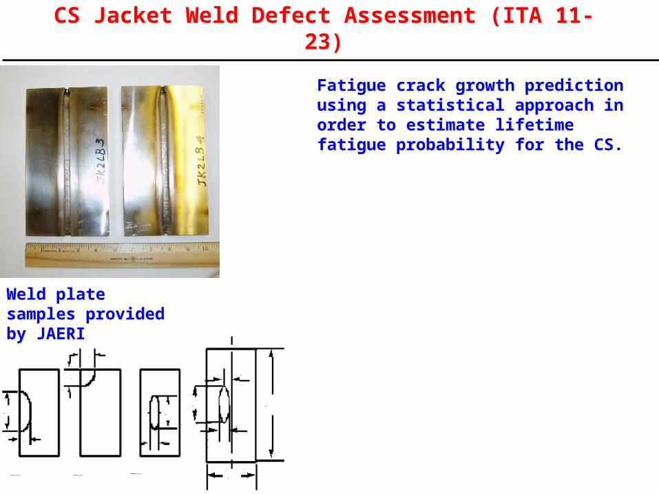
CS Jacket Weld Defect Assessment (ITA 11-23)
Fatigue crack growth prediction using a statistical approach in order to estimate lifetime fatigue probability for the CS.
Weld plate samples provided by JAERI
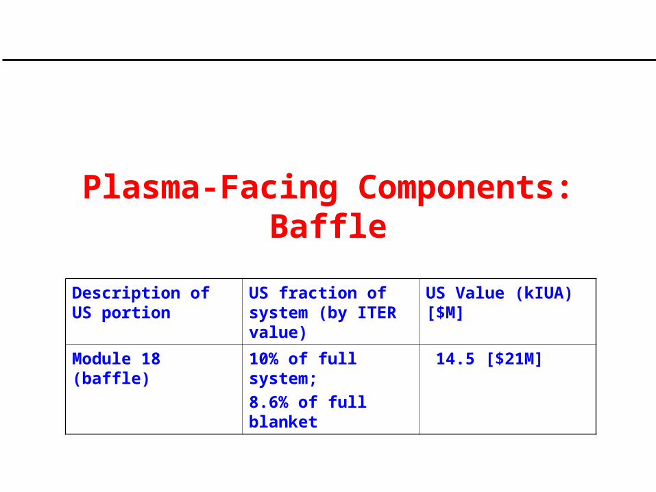
Plasma-Facing Components:Baffle
Description of US portion
US fraction of system (by ITER value)
US Value (kIUA) [$M]
Module 18 (baffle) 10% of full system;
8.6% of full blanket
14.5 [$21M]
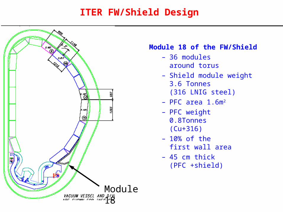
ITER FW/Shield Design
Module 18
Module 18 of the FW/Shield– 36 modules
around torus– Shield module weight
3.6 Tonnes (316 LNIG steel)
– PFC area 1.6m2
– PFC weight 0.8Tonnes (Cu+316)
– 10% of the first wall area
– 45 cm thick (PFC +shield)
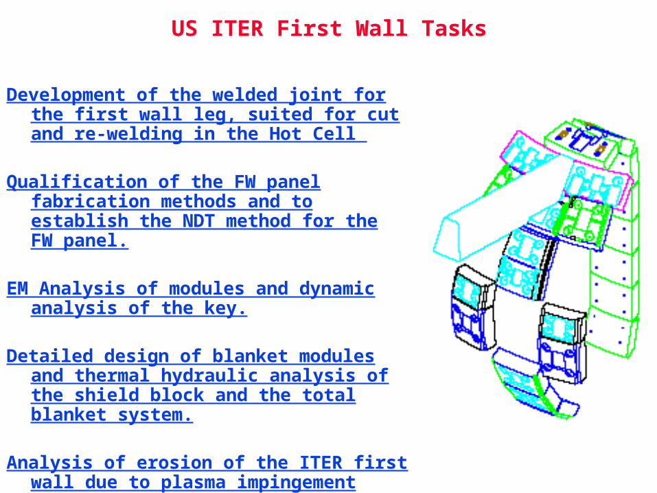
US ITER First Wall Tasks
Development of the welded joint for the first wall leg, suited for cut and re-welding in the Hot Cell
Qualification of the FW panel fabrication methods and to establish the NDT method for the FW panel.
EM Analysis of modules and dynamic analysis of the key.
Detailed design of blanket modules and thermal hydraulic analysis of the shield block and the total blanket system.
Analysis of erosion of the ITER first wall due to plasma impingement
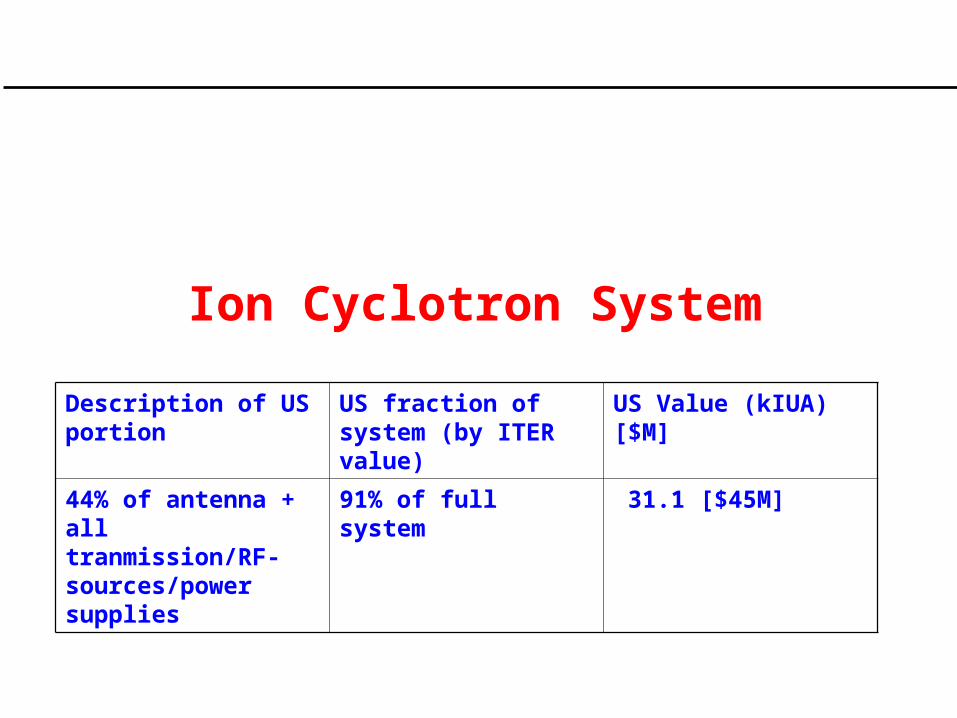
Ion Cyclotron System
Description of US portion
US fraction of system (by ITER value)
US Value (kIUA) [$M]
44% of antenna + all tranmission/RF-sources/power supplies
91% of full system 31.1 [$45M]
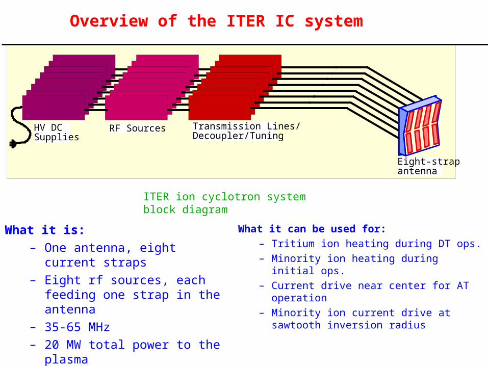
Overview of the ITER IC system
What it is:
– One antenna, eight current straps
– Eight rf sources, each feeding one strap in the antenna
– 35-65 MHz
– 20 MW total power to the plasma
– Variable phasing between straps
What it can be used for:
– Tritium ion heating during DT ops.
– Minority ion heating during initial ops.
– Current drive near center for AT operation
– Minority ion current drive at sawtooth inversion radius
ITER ion cyclotron system block diagram
HV DCSupplies
RF Sources Transmission Lines/Decoupler/Tuning
Eight-strapantenna
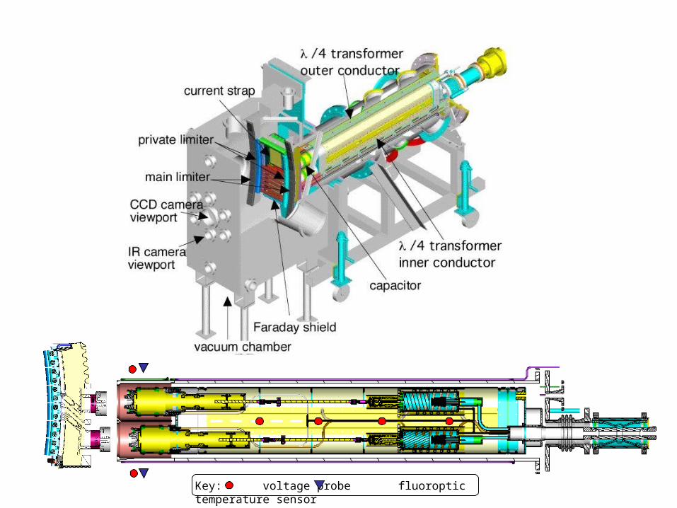
Key: voltage probe fluoroptic temperature sensor
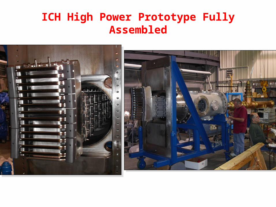
ICH High Power Prototype Fully Assembled
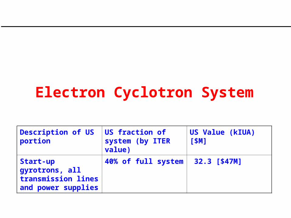
Electron Cyclotron System
Description of US portion
US fraction of system (by ITER value)
US Value (kIUA) [$M]
Start-up gyrotrons, all transmission lines and power supplies
40% of full system 32.3 [$47M]
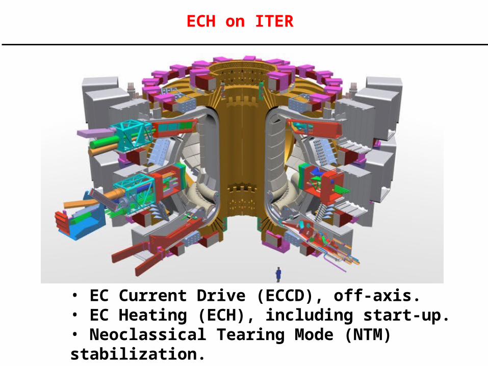
• EC Current Drive (ECCD), off-axis.• EC Heating (ECH), including start-up.• Neoclassical Tearing Mode (NTM) stabilization.
ECH on ITER
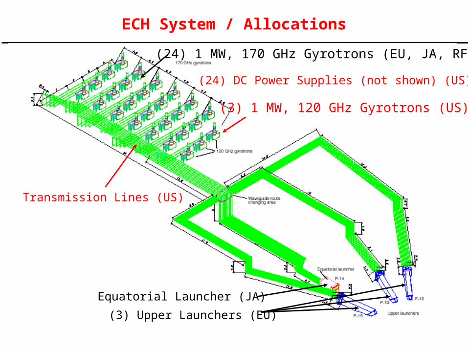
(24) 1 MW, 170 GHz Gyrotrons (EU, JA, RF)
(3) 1 MW, 120 GHz Gyrotrons (US)
Transmission Lines (US)
Equatorial Launcher (JA)
(3) Upper Launchers (EU)
(24) DC Power Supplies (not shown) (US)
ECH System / Allocations
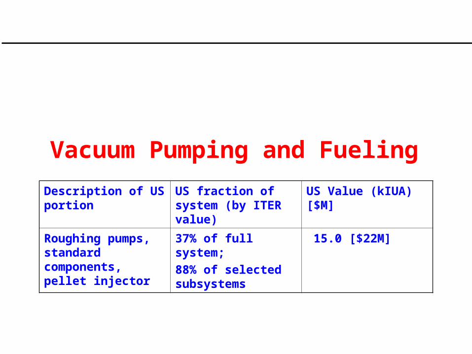
Vacuum Pumping and Fueling
Description of US portion
US fraction of system (by ITER value)
US Value (kIUA) [$M]
Roughing pumps, standard components, pellet injector
37% of full system;
88% of selected subsystems
15.0 [$22M]
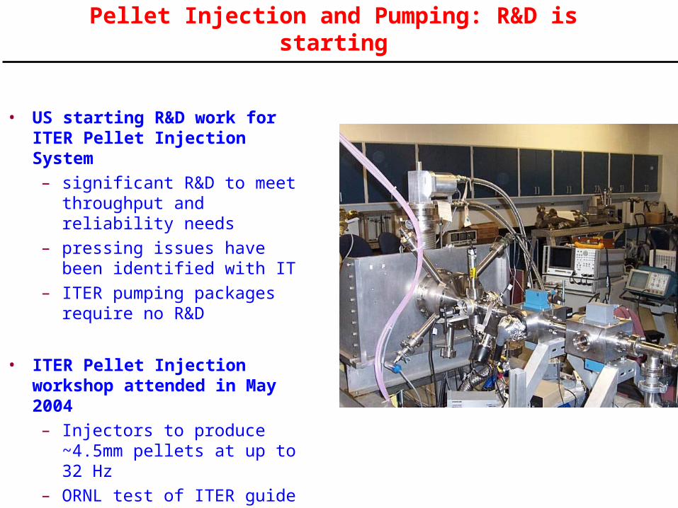
Pellet Injection and Pumping: R&D is starting
• US starting R&D work for ITER Pellet Injection System
– significant R&D to meet throughput and reliability needs
– pressing issues have been identified with IT
– ITER pumping packages require no R&D
• ITER Pellet Injection workshop attended in May 2004
– Injectors to produce ~4.5mm pellets at up to 32 Hz
– ORNL test of ITER guide tube mockup is underway
– Gas gun approach for injector is under investigation
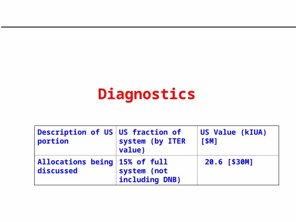
Diagnostics
Description of US portion
US fraction of system (by ITER value)
US Value (kIUA) [$M]
Allocations being discussed
15% of full system (not including DNB)
20.6 [$30M]
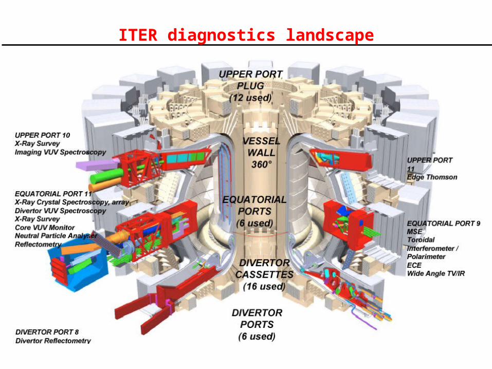
ITER diagnostics landscape
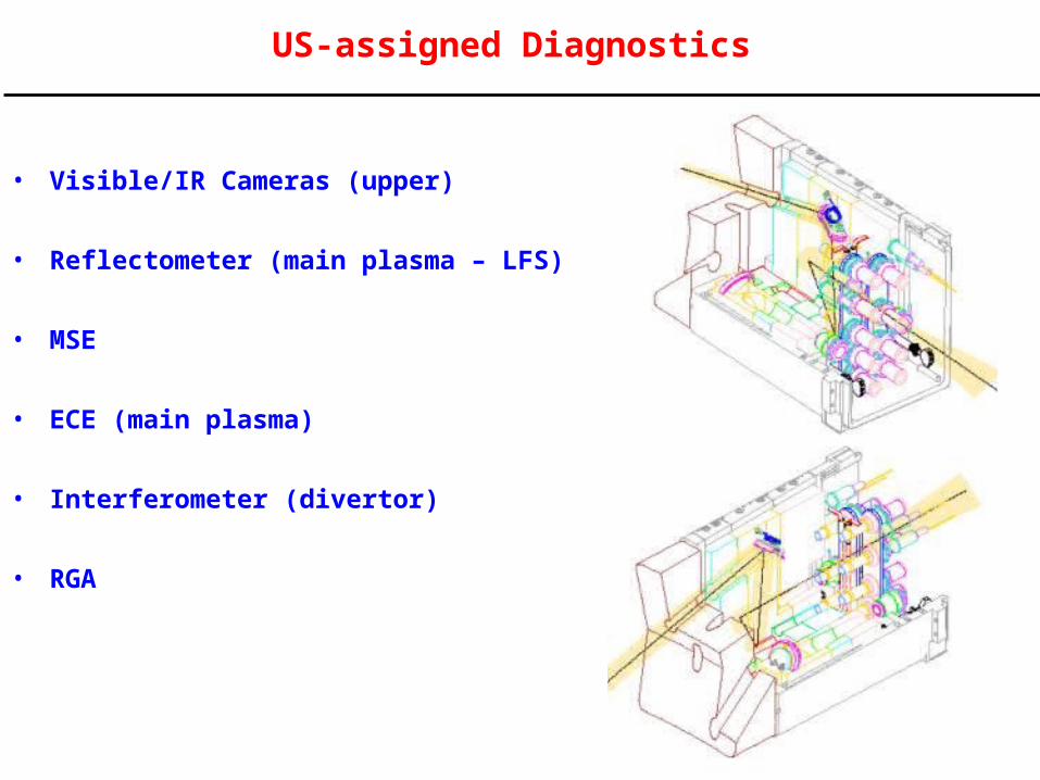
US-assigned Diagnostics
• Visible/IR Cameras (upper)
• Reflectometer (main plasma – LFS)
• MSE
• ECE (main plasma)
• Interferometer (divertor)
• RGA
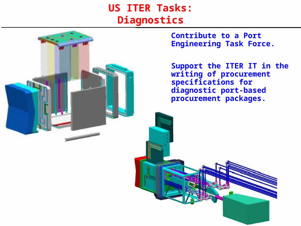
US ITER Tasks:Diagnostics
Contribute to a Port Engineering Task Force.
Support the ITER IT in the writing of procurement specifications for diagnostic port-based procurement packages.
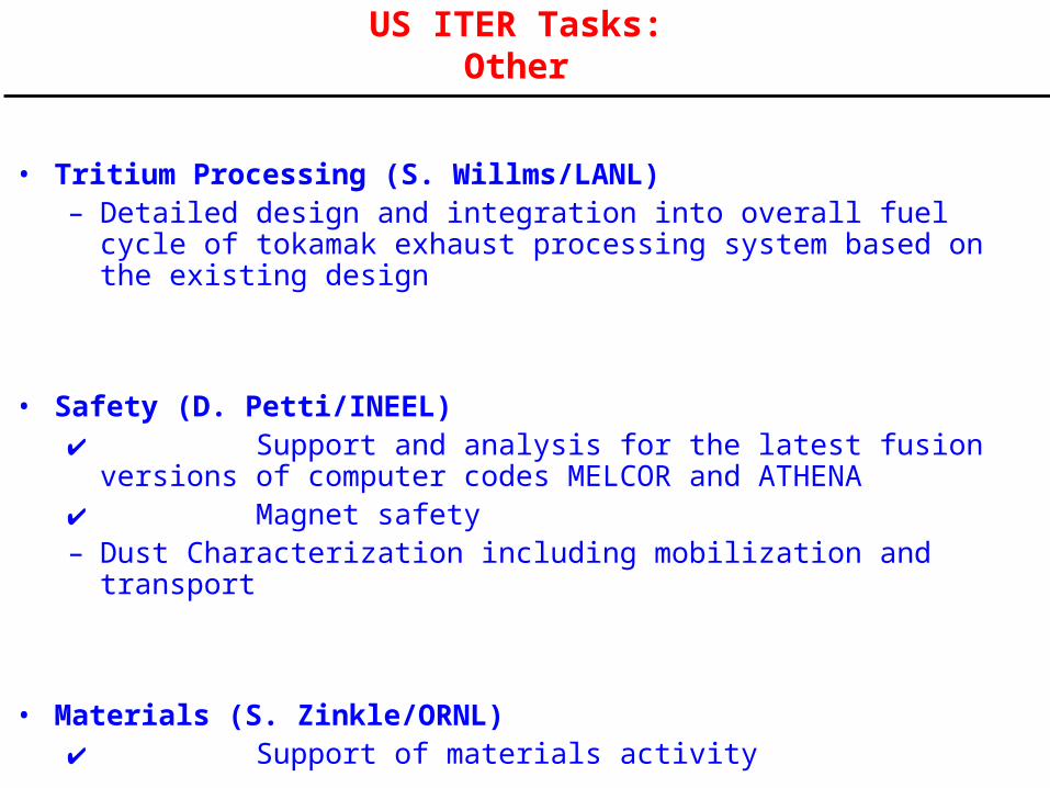
US ITER Tasks: Other
• Tritium Processing (S. Willms/LANL)– Detailed design and integration into overall fuel cycle of tokamak
exhaust processing system based on the existing design
• Safety (D. Petti/INEEL) Support and analysis for the latest fusion versions of computer codes
MELCOR and ATHENA Magnet safety– Dust Characterization including mobilization and transport
• Materials (S. Zinkle/ORNL) Support of materials activity
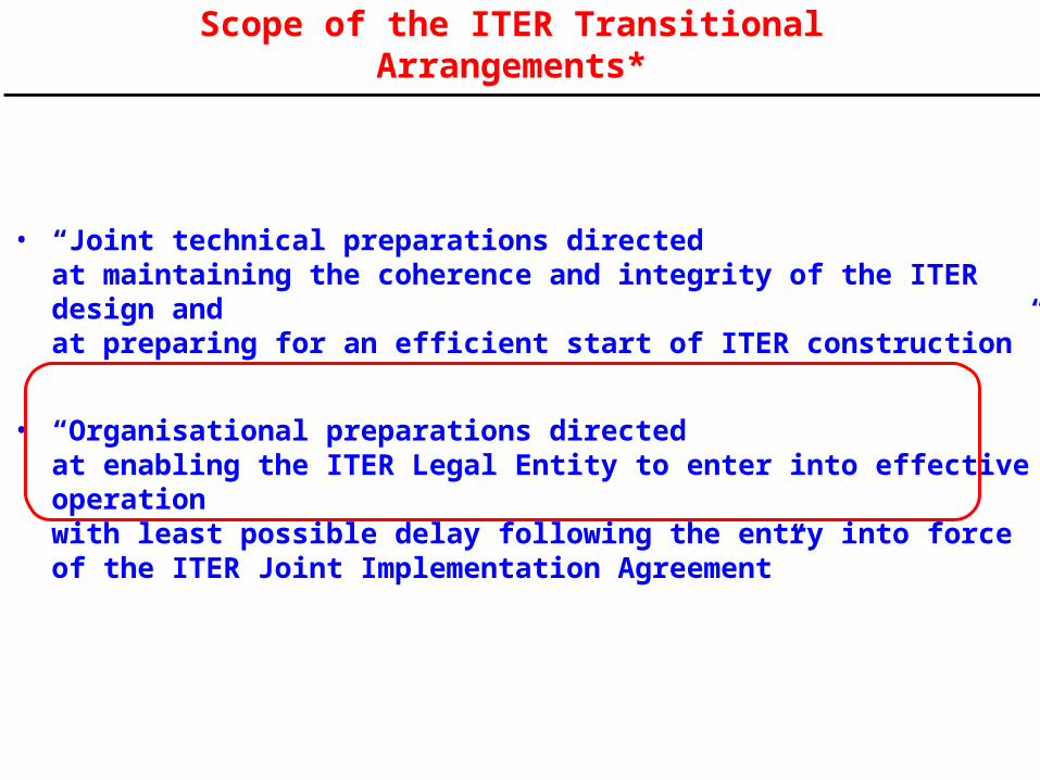
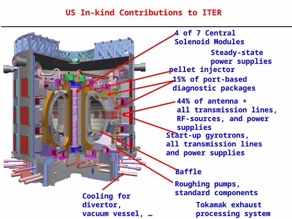
Scope of the ITER Transitional Arrangements*
• “Joint technical preparations directed at maintaining the coherence and integrity of the ITER design and at preparing for an efficient start of ITER construction”
• “Organisational preparations directed at enabling the ITER Legal Entity to enter into effective operation with least possible delay following the entry into force of the ITER Joint Implementation Agreement”
Approved
Approved
Approved
Approved
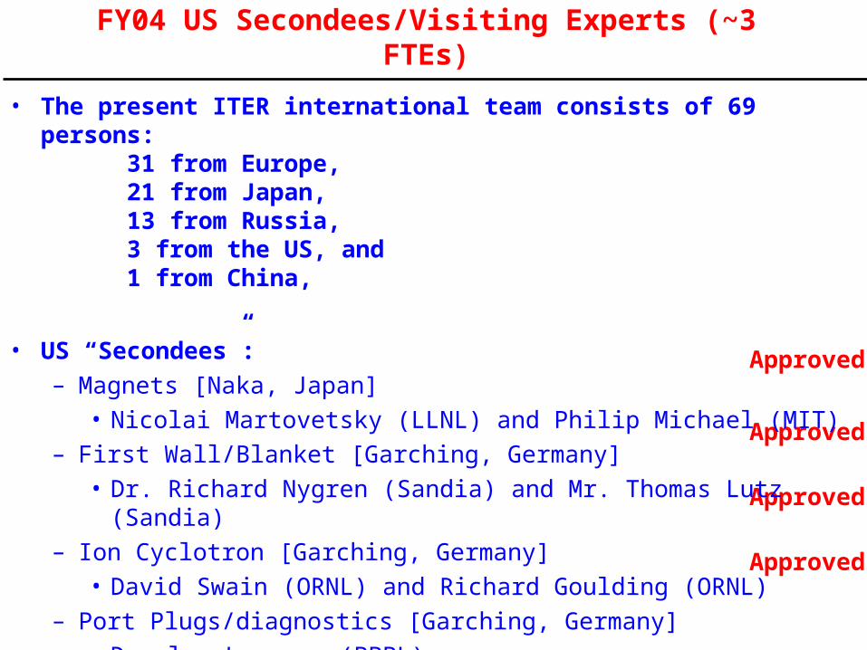
FY04 US Secondees/Visiting Experts (~3 FTEs)
• The present ITER international team consists of 69 persons:31 from Europe, 21 from Japan, 13 from Russia, 3 from the US, and 1 from China,
• US “Secondees”:– Magnets [Naka, Japan]
• Nicolai Martovetsky (LLNL) and Philip Michael (MIT)– First Wall/Blanket [Garching, Germany]
• Dr. Richard Nygren (Sandia) and Mr. Thomas Lutz (Sandia)– Ion Cyclotron [Garching, Germany]
• David Swain (ORNL) and Richard Goulding (ORNL)– Port Plugs/diagnostics [Garching, Germany]
• Douglas Loesser (PPPL)
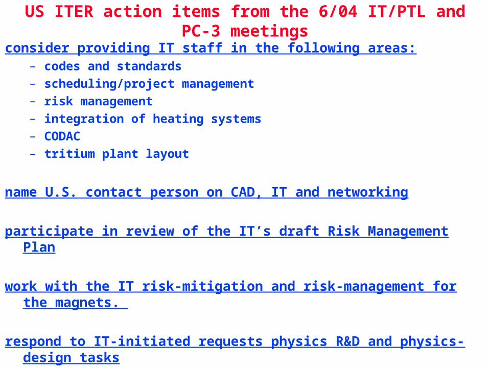
US ITER action items from the 6/04 IT/PTL and PC-3 meetings
consider providing IT staff in the following areas:– codes and standards
– scheduling/project management
– risk management
– integration of heating systems
– CODAC
– tritium plant layout
name U.S. contact person on CAD, IT and networking
participate in review of the IT’s draft Risk Management Plan
work with the IT risk-mitigation and risk-management for the magnets.
respond to IT-initiated requests physics R&D and physics-design tasks
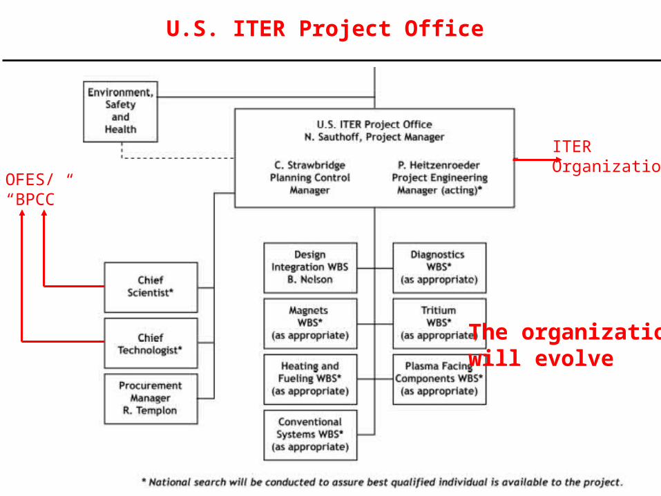
U.S. ITER Project Office
OFES/ “BPCC”
ITEROrganization
The organizationwill evolve
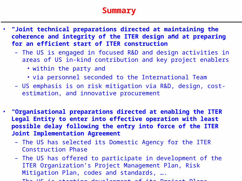
Summary
• “Joint technical preparations directed at maintaining the coherence and integrity of the ITER design and at preparing for an efficient start of ITER construction”
– The US is engaged in focused R&D and design activities in areas of US in-kind contribution and key project enablers
• within the party and
• via personnel seconded to the International Team
– US emphasis is on risk mitigation via R&D, design, cost-estimation, and innovative procurement
• “Organisational preparations directed at enabling the ITER Legal Entity to enter into effective operation with least possible delay following the entry into force of the ITER Joint Implementation Agreement”
– The US has selected its Domestic Agency for the ITER Construction Phase
– The US has offered to participate in development of the ITER Organization’s Project Management Plan, Risk Mitigation Plan, codes and standards, ….
– The US is starting development of its Project Plans
– The US ITER Project Office is drafting processes for open team-building