Embed Size (px)
Citation preview

ITEC420: Software Engineering Lecture 4: Recap Requirement.. Analysis, Design Workflows Box Leangsuksun SWECO Endowed Professor, Computer Science Louisiana Tech University [email protected]
CTO, PB Tech International Inc. [email protected]

The Unified Modeling Language
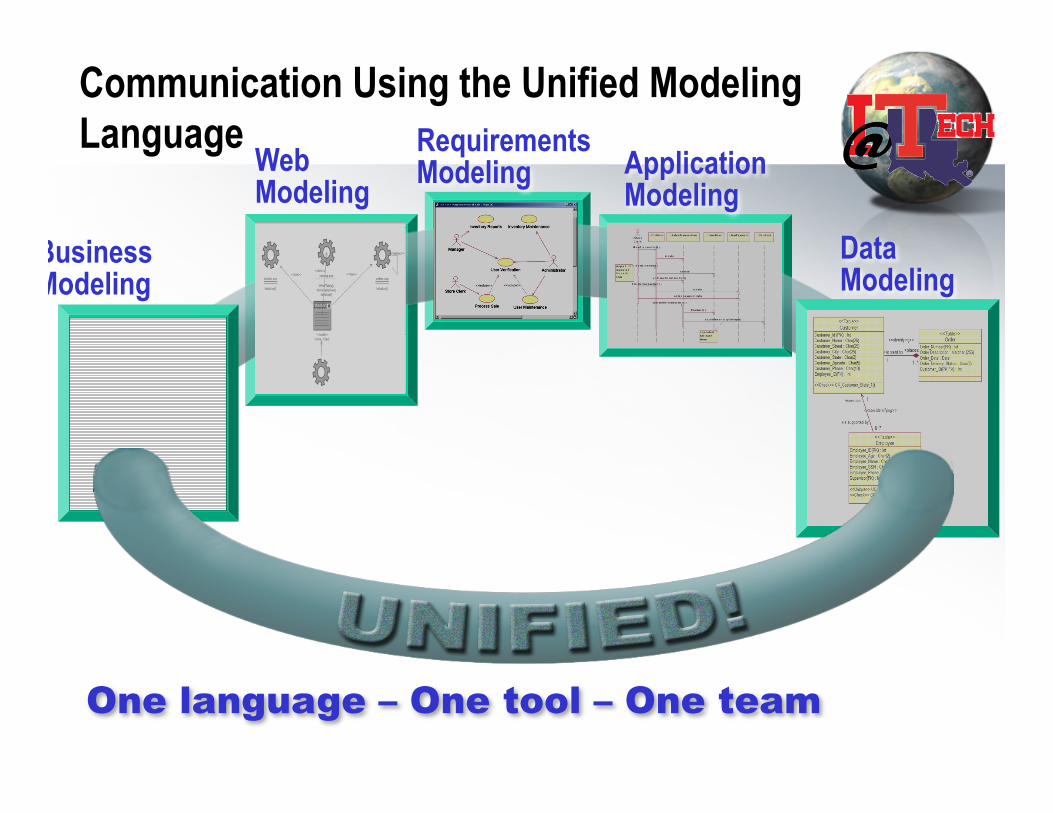
Communication Using the Unified Modeling Language
Data Modeling
Web Modeling
One language – One tool – One team
Application Modeling
Business Modeling
Requirements Modeling
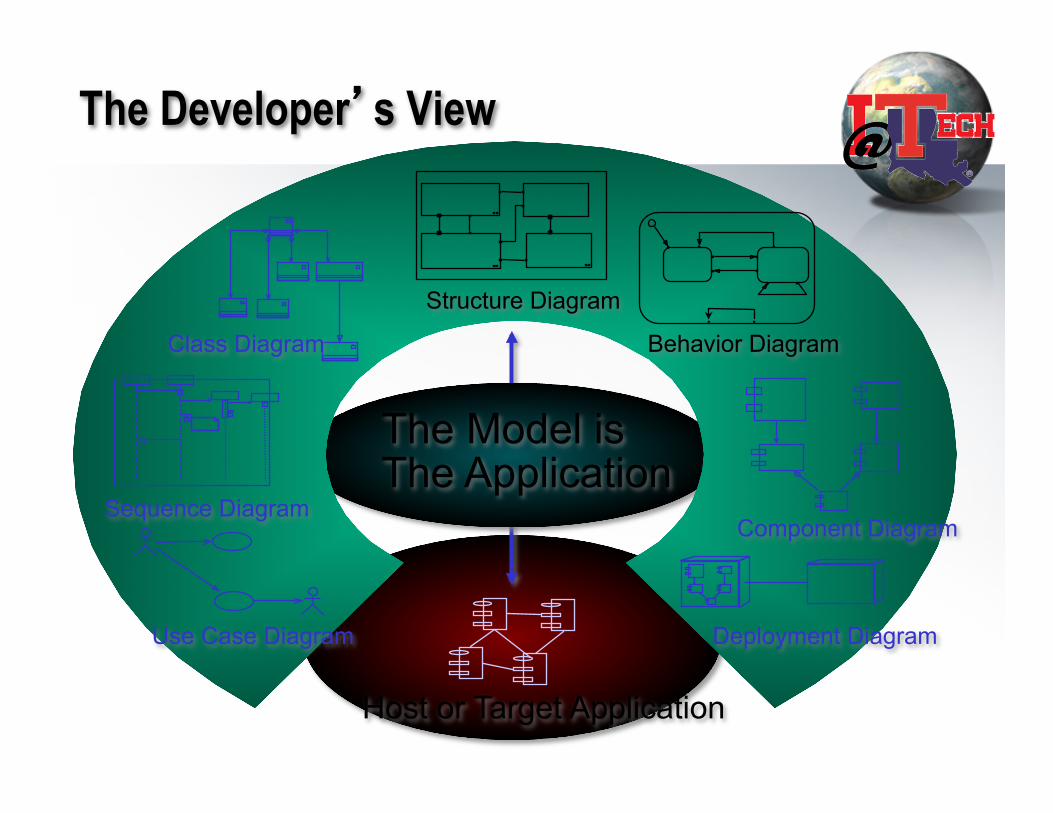
Host or Target Application
The Developer’s View
The Model is The Application
Use Case Diagram
Sequence Diagram
Class Diagram
Structure Diagram
Behavior Diagram
Component Diagram
Deployment Diagram

UML Models
• Models capture – the structural, or static, features of systems – the behavioral, or dynamic, features of systems.
• Models have several independent dimensions – Each emphasize particular qualities of a model – Each dimension has a diagram type
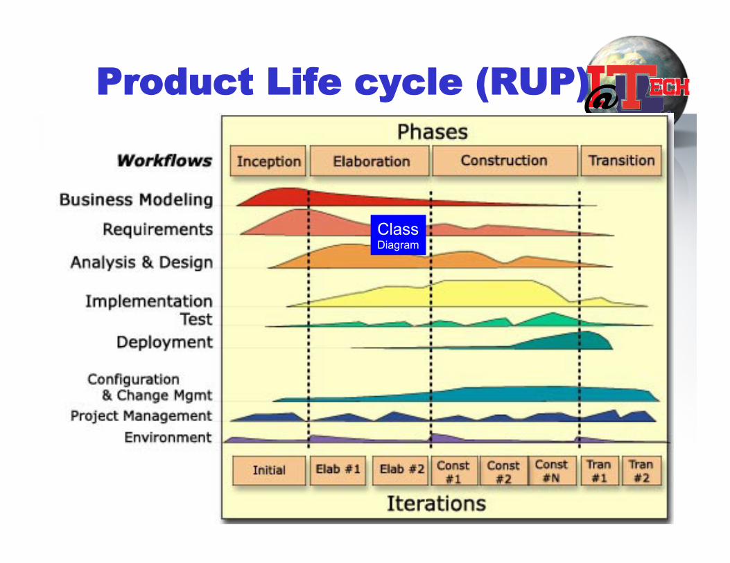
Product Life cycle (RUP)
Class Diagram
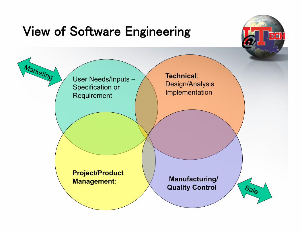
View of Software Engineering
User Needs/Inputs – Specification or Requirement
Technical: Design/Analysis Implementation
Project/Product Management:
Manufacturing/ Quality Control

Typical SE life cycle process
• User Inputs -> Requirements and Specification • Design & Analysis -> Analysis & Design documents • Implementation -> Programming, integration, Tools ->
Code or system • Testing -> Test Plan & Test results • Manufacturing, installation/Deployment and Quality
Control -> Change Management & Configuration Management.
• A classic water model.. Not good..why? • the above SE workflow can be divided into smaller
iterations

Recap: Requirements workflow
Requirements and Specifications
• User Inputs/expectations are translated into agreement documents among users/customers and various stakeholders in SE lifecycle
• Can be legal documents between client and supplier
• How do we know whether the software product will meet the expectation?
Requirements and Specifications
• Functional Requirements – Tangible Needs – E.g. your order processing system, online store with shopping cart.
• Non-Functional Requirements – Performance (how well your system can perform, # transaction) – Reliability (how long your system can run w/o failure or what is
uptime?)
• How do we know whether the software product will meet the expectation?
What are requirements? • “What customers or users expect from the
system” • Two types
– Functional Requirements • Features (more tangible)
– Non-functional requirements • Reliability and performance (equally if not more)

Capture requirement
• Reach agreement on system context – provided by customers – Vision statement (e.g from marketing/product team) – Survey or research
- Communication. - Articulation. - Clarity. • Come up with Abstractions of a given problem
domain • Arrive at actions representing/involving the
abstractions (USE-CASES)
Requirements definition vs specifications • Requirements definition
– A statement in natural language plus diagrams of the services the system provides and its operational constraints. Written for customers
• Requirements specification – A structured document setting out detailed descriptions of
the system services. Written as a contract between client and contractor
• Software specification – A detailed software description which can serve as a
basis for a design or implementation. Written for developers
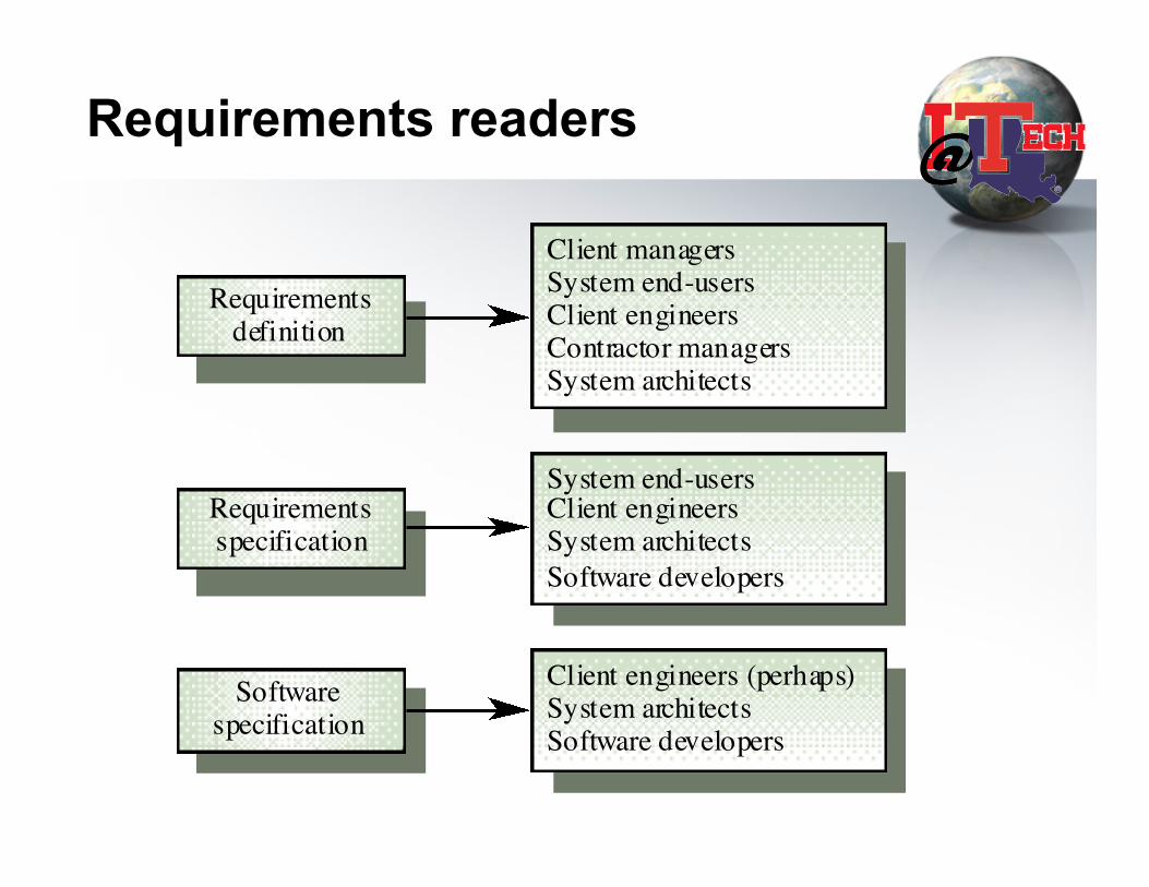
Requirements readers
Client managersSystem end-usersClient engineersContractor managersSystem architects
System end-usersClient engineersSystem architectsSoftware developers
Client engineers (perhaps)System architectsSoftware developers
Requirementsdefinition
Requirementsspecification
Softwarespecification
USE CASE
• A series of actions that an actor performs in conjunction with a system to achieve a particular goal
• It only describes what but not the how a system needs to do.
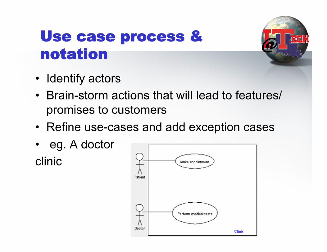
Use case process & notation
• Identify actors • Brain-storm actions that will lead to features/
promises to customers • Refine use-cases and add exception cases • eg. A doctor clinic

USE CASE : An Actor
Represents either a role (user) or an entity that interacts but is outside the system.

More actor (excerpted from wiki)
• an actor is something or someone who supplies a stimulus to the system. An actor cannot be controlled by the system and is defined as being outside the system.
• An actor is often thought of as a role, rather than an actual person or system. A single person in the real world can be represented by several actors if they have several different roles and goals in regard to a system.
USE CASE types
• Main flow of events • Exceptional flow of events
Workers
• System Analyst. • Use case specifier • User-interface designer • architect
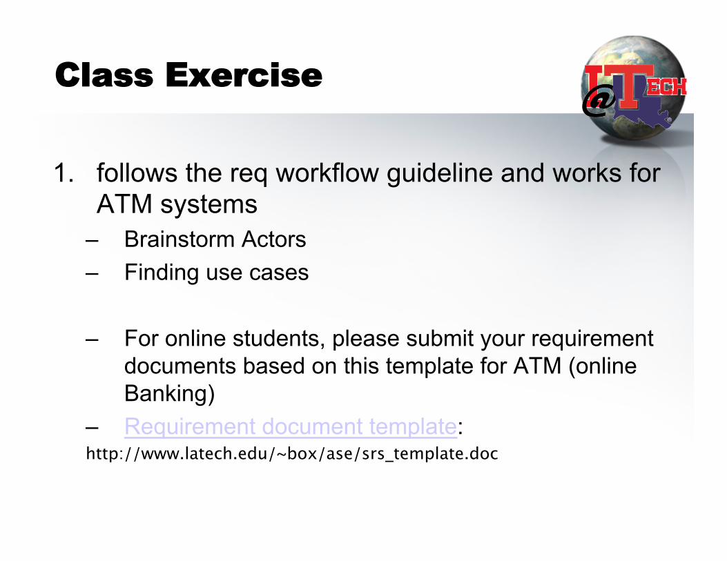
Class Exercise
1. follows the req workflow guideline and works for ATM systems
– Brainstorm Actors – Finding use cases
– For online students, please submit your requirement documents based on this template for ATM (online Banking)
– Requirement document template: http://www.latech.edu/~box/ase/srs_template.doc
The Analysis Workflow
This presentation will probably
involve audience discussion, which will create action items. Use PowerPoint to keep track of these action items during your presentation
• In Slide Show, click on the
right mouse button • Select “Meeting Minder” • Select the “Action Items” tab • Type in action items as they
come up • Click OK to dismiss this box This will automatically create
an Action Item slide at the end of your presentation with your points entered.
Main Goal
Understand customers requirements to gain momentum towards design.
Primary Result – Analysis Model
• Artifacts • Workers • Activities

Purpose of Analysis & Design
• To transform the requirements into a design of the system to-be.
• To evolve a robust architecture for the system. • To adapt the design to match the implementation
environment, designing it for performance.
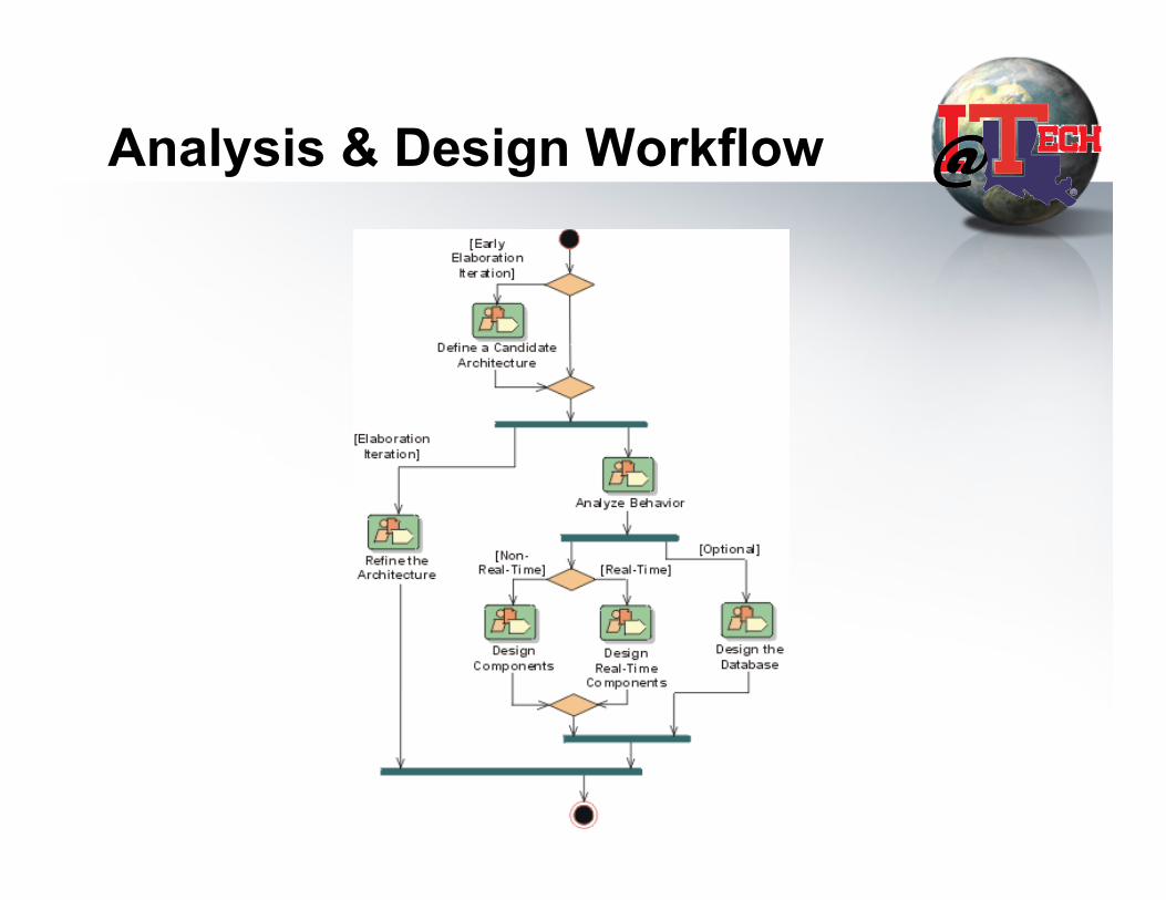
Analysis & Design Workflow
What is system architecture?
• A blueprint for software system • Includes
– High Level Software components/subsystem – High Level Hardware components/subsystem – Relationship/connectivity – Data Models (optional)
12/24/13 27
Define Candidate Architecture
• Create an initial sketch of the architecture of the system
• Identify analysis classes from the architecturally significant use cases
• Update the use-case realizations with analysis class interactions

Analysis Artifacts (UML)
Robustness Diagram: Usually contains attributes, not operations. • Boundary Classes • Control Classes • Entity Classes
Symbol:
Symbol:
Symbol:
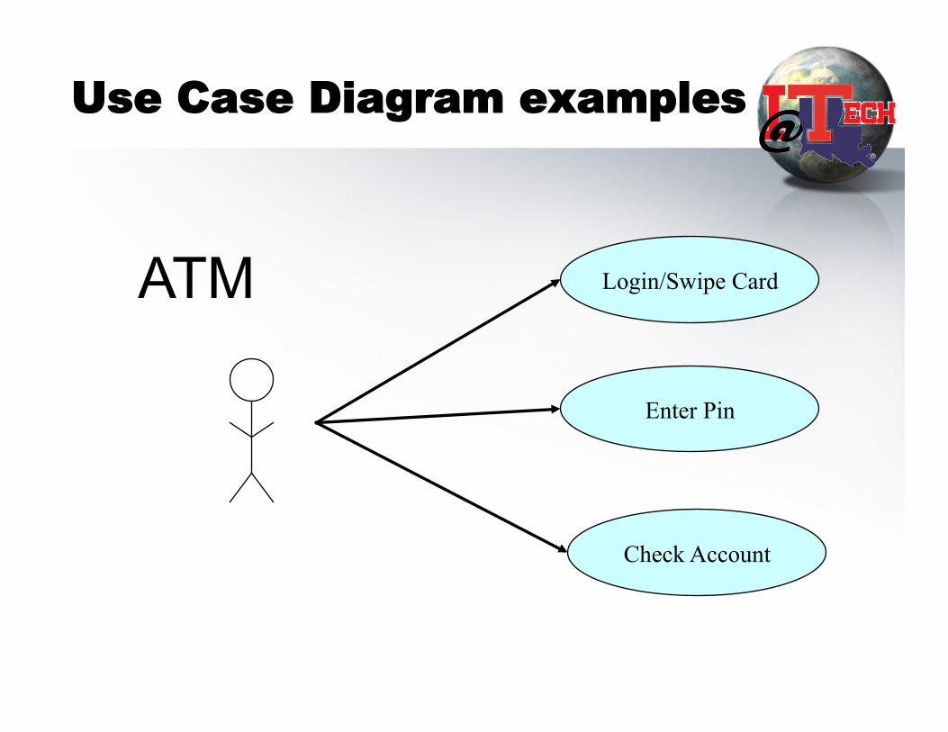
Use Case Diagram examples
Login/Swipe Card
Enter Pin
Check Account
ATM
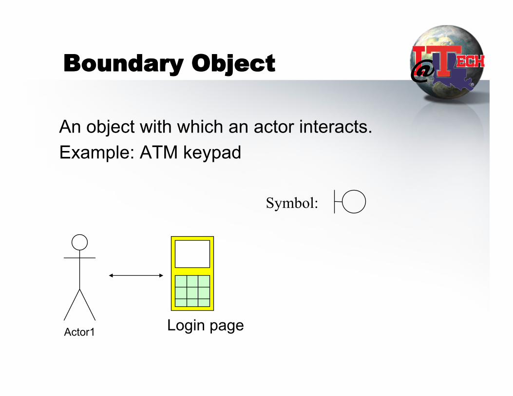
Boundary Object
An object with which an actor interacts. Example: ATM keypad
Symbol:
Login page Actor1

Control Object
An object that embodies application logic. Example: Validation
Authenticated
Validation
Symbol:
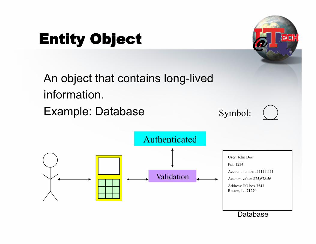
Entity Object
An object that contains long-lived information. Example: Database Symbol:
Authenticated
Validation
User: John Doe
Pin: 1234
Account number: 111111111
Account value: $25,678.56
Address: PO box 7543 Ruston, La 71270
Database
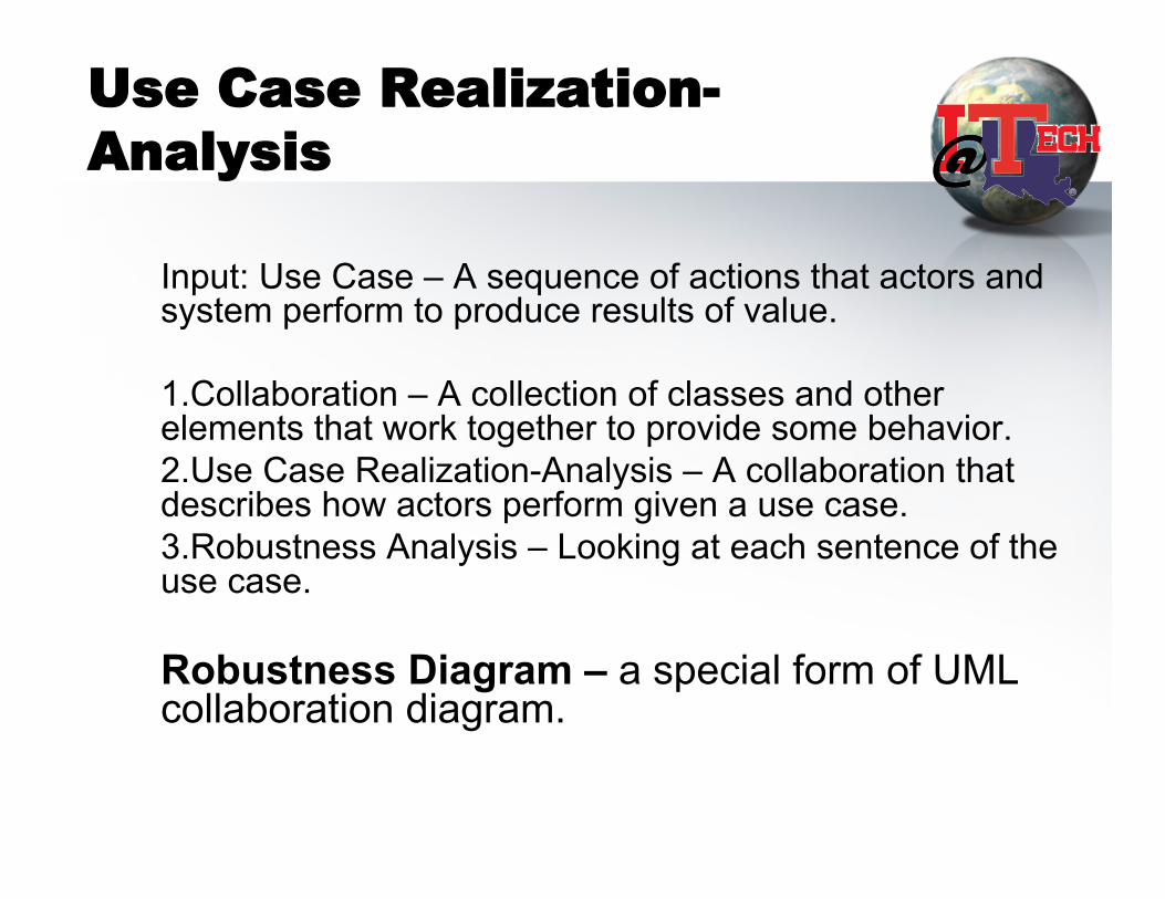
Use Case Realization-Analysis
Input: Use Case – A sequence of actions that actors and system perform to produce results of value. 1. Collaboration – A collection of classes and other elements that work together to provide some behavior. 2. Use Case Realization-Analysis – A collaboration that describes how actors perform given a use case. 3. Robustness Analysis – Looking at each sentence of the use case. Robustness Diagram – a special form of UML collaboration diagram.

Example of Robustness Diagram: Login usecase
Authenticated
Validation
User: John Doe
Pin: 1234
Account number: 111111111
Account value: $25,678.56
Address: PO box 7543 Ruston, La 71270
Validation Account ATM Keypad
Actor
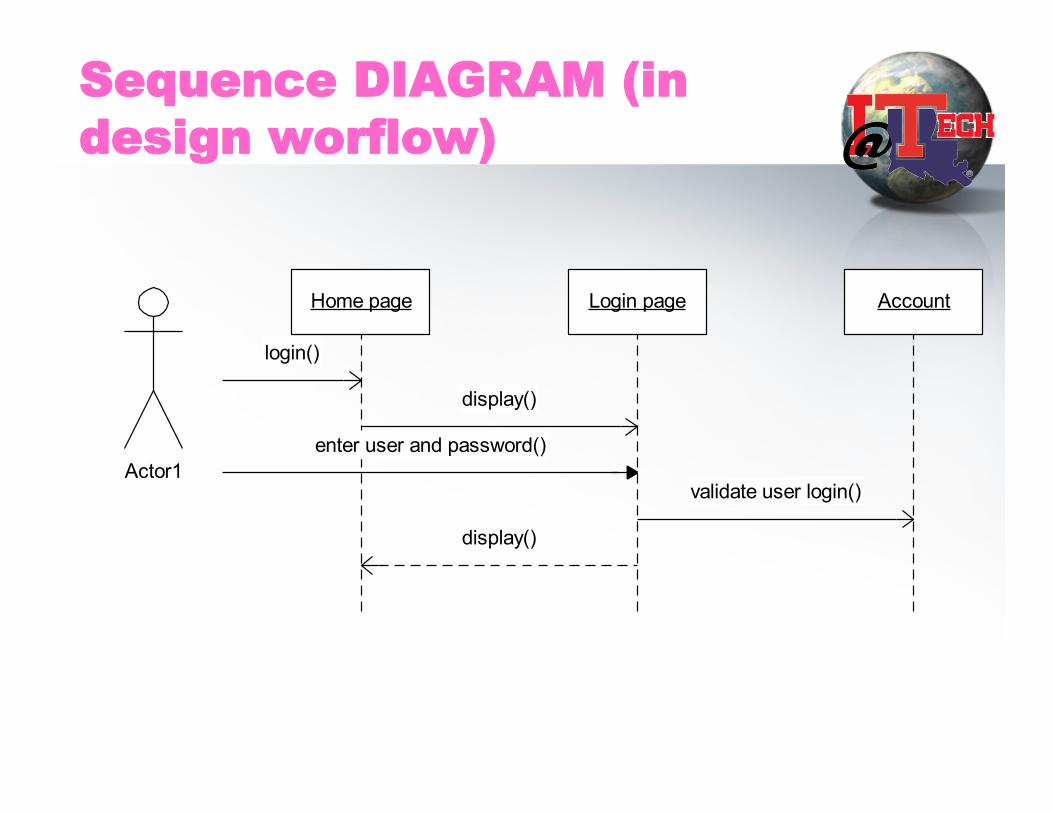
Sequence DIAGRAM (in design worflow)
Home page Login page Account
login()
display()
enter user and password()
validate user login()
display()
Actor1
Analysis Package and Analysis Model:-
• Analysis Package – UML package that contains analysis classes and use case realizations-analysis.
• Analysis Model – – Architecture Description – View of analysis model. - Analysis packages and relationships - Use case realization-analysis - Analysis classes participating in the use case
realization-analysis
Workers
• ARCHITECT:-
Within the analysis workflow, the architect is responsible for
– outlining the analysis model
Workers
USE CASE ENGINEER:- " Builds use case realizations-analysis. COMPONENT ENGINEER:-architect and developers
o Ensuring that the analysis classes and use case realizations defined by the use case engineer (s) work well together.
o Getting the contents of one or more analysis packages.
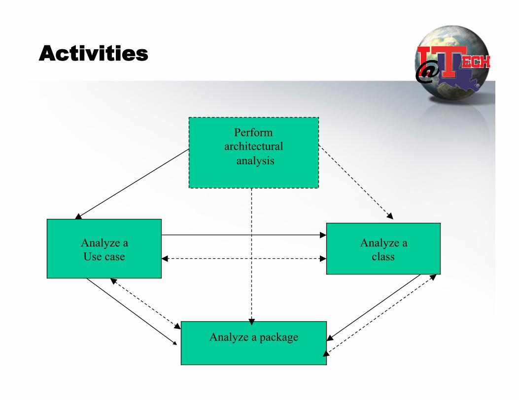
Activities
Perform architectural
analysis
Analyze a Use case
Analyze a class
Analyze a package
Perform Architectural Analysis:-
• Creating outlines of the analysis model and the architecture as a whole
• Identifying the first cut of packages that the development team will define while performing the following activities–
Analyze a Use Case and Analyze a Class

Analyze a Use Case
• Building a use case realization-analysis for a use case.
Analyze a Class:-
• Expanding the definition of analysis class • A component engineer is responsible for this
activity • Refining and expanding the various kinds of
relationships that each analysis class is involved in.
• Highly cohesive and loosely coupled components are desirable.
Analyze a Package:-
• Building an analysis package that was defined during architectural analysis.
• Component engineer plays a vital role. • Traceability between the packages should be high. • Architect captures the changes to the analysis
packages and ensures that the changes don’t threaten the integrity of the architecture.
Class Exercise
• Each group to perform your analysis workflow for our e-mail problem. Says we’ll support – registration, login, read/send usecases. – Analysis Model - Usecases realization-analysis
• 3 type of objects and their relatioinship
Design Workflow
INTRODUCTION
• GOAL OF DESIGN WORKFLOW • RESULTS • DESIGN MODEL • DEPLOYMENT MODEL
GOAL OF DESIGN WORKFLOW
EXPANSIONS OF THE ANALYSIS MODEL • MOSTLY PHYSICAL • MORE DETAILED • SHOWS THE DECISIONS
• Capture how internal working of the system at the object-level
ARTIFACTS
• CLASS DESIGN & various static & dynamic structure
• USE CASE REALIZATION-DESIGN • DESIGN MODEL • DEPLOYMENT MODEL
DESIGN MODEL
• Class Design – Class Diagram
• Use Case Realization-Design – sequence diagram or – collaboration diagram – Statechart diagram – Activity diagram
12/24/13 50
CLASS DESIGN
• CONTAINS collection of classes with FULL SET OF ATTRIBUTES and perhaps with relationships
• Can be EXPRESSED IN PROGRAMMING LANGUAGES
• ACTIVITY DIAGRAM (flowchart & typically for each class)
• STATECHART DIAGRAM
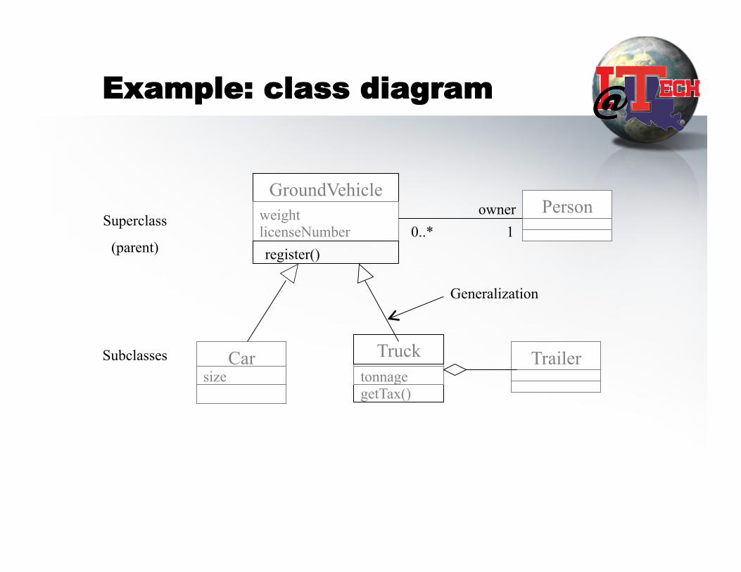
Example: class diagram
GroundVehicle weight licenseNumber register()
Person
Car size
getTax()
Truck tonnage
Trailer
0..* 1 owner
Generalization
Superclass
(parent)
Subclasses

Activity Diagram (flow chart)
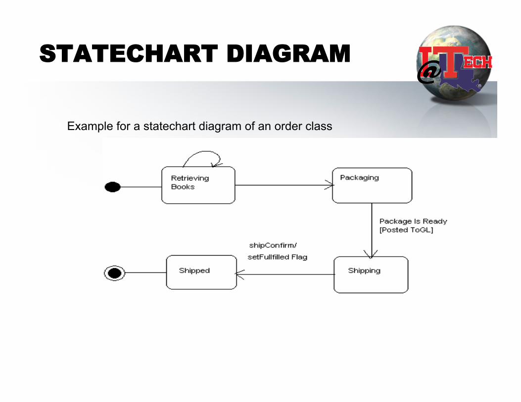
STATECHART DIAGRAM
Example for a statechart diagram of an order class
Use Case Realization-Design
For each use case, shows interactions among classes (in an ordered sequence)
• Sequence diagram
• Collaboration diagram
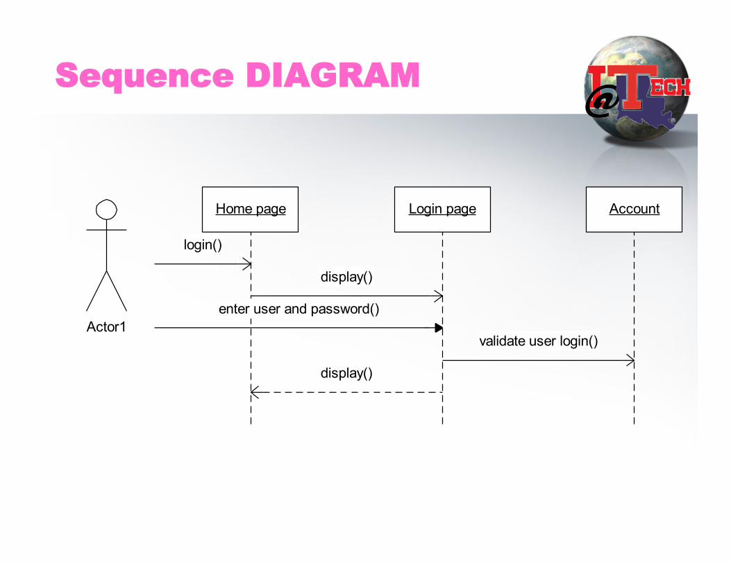
Sequence DIAGRAM
Home page Login page Account
login()
display()
enter user and password()
validate user login()
display()
Actor1
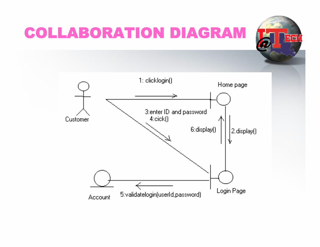
COLLABORATION DIAGRAM

Artifacts Contd.
• Design subsystem
• Design model
• Deployment model
• Design package
WORKERS
• Architect • Use case engineer • Component engineer
ACTIVITIES
• Perform architectural design Design a subsystem
• Design a use case realization (interaction) • Design a class
architectural design
• Come up with a system layout – Subsystems -> component/interface
• Top down vs bottom up
Deployment Diagram
Deployment
• a static view of hw configuration and software components that run on those systems – hardware – the software on the hardware – the middleware connecting the disparate machines to one another.
• Notation: – 3-D box represents a node, either software or hardware – HW node can be signified with <<stereotype>> – Connections between nodes are represented with a line, with optional
<<stereotype>> – Nodes can reside within a node

Sample of Deployment Diagram (1)
This diagram is excerpted from intro to UML 2 deployment diagram, http://www.agilemodeling.com/artifacts/deploymentDiagram.htm
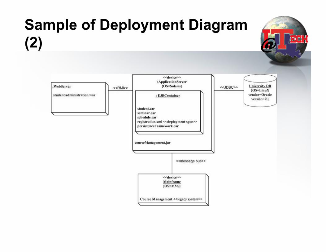
Sample of Deployment Diagram (2)
This diagram is excerpted from intro to UML 2 deployment diagram, http://www.agilemodeling.com/artifacts/deploymentDiagram.htm
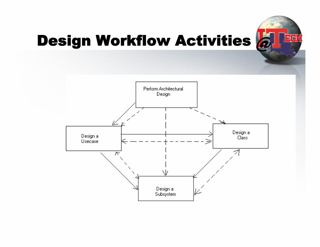
Design Workflow Activities
Group exercise
• Each group to perform your design workflow for our e-mail problem. Says we’ll support –registration & login, read/send. – class design, subsystem design, collaboration/
sequence diagram , state diagram