Embed Size (px)
Citation preview

ITEC 275 Computer Networks – Switching, Routing, and
WANs
Week 9Robert D’Andrea
2015
Agenda• Learning Activities
– Network Management Processes• Syslog
– Network Management Architectures– Network Management Tools and Protocols– Campus Cabling– Ethernet– Campus Network Design Example
Network Management Processes
• International Organization for Standardization (ISO) defines five types of network processes– Fault management– Configuration management– Accounting management– Performance management– Security management
Network Management Processes• Fault management refers to detecting, isolating, diagnosing,
and correcting problems.
- Develop a workarounds
- Test the workaround
- Document the workaround in a problem- tracking database
- Utilize monitoring tools to alert managers, protocol analyzers and Wire Shark for fault resolution
- Syslog network contains timestamp, level, and facility. Syslog severity levels are provided
Network Management Processes• Syslog is a standard for computer message
logging.
Syslog can be used for computer system management and security auditing as well as generalized informational, analysis, and debugging messages. It is supported by a wide variety of devices (like printers and routers) and receivers across multiple platforms. Because of this, syslog can be used to integrate log data from many different types of systems into a central repository.
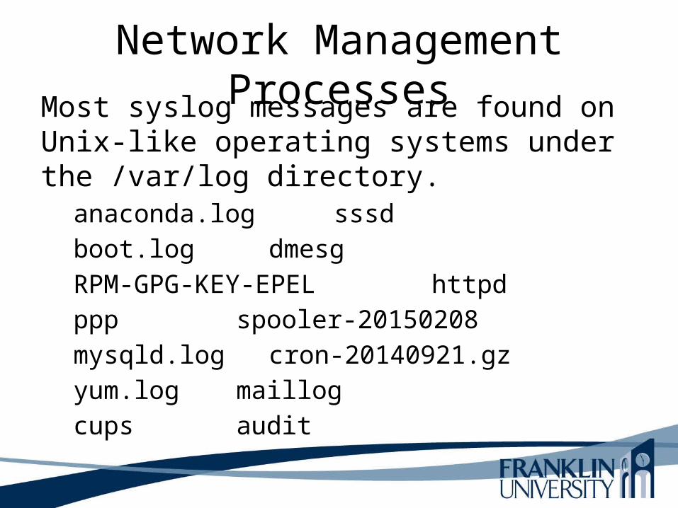
Network Management ProcessesMost syslog messages are found on Unix-like operating systems under the /var/log directory.
anaconda.log sssd
boot.log dmesg
RPM-GPG-KEY-EPEL httpd
ppp spooler-20150208
mysqld.log cron-20140921.gz
yum.log maillog
cups audit

Network Management ProcessesAnaconda is the installation program used by Fedora,
Red Hat Enterprise Linux.
During an installation, a target computer's hardware is identified and configured and the appropriate file systems for the system's architecture are created. Finally, Anaconda allows the user to install the operating system software on the target computer.
Anaconda can also upgrade existing installations of earlier versions of the same distribution. After the installation is complete, you can reboot into your installed system and continue doing customization using the initial setup program.

Network Management Processes• Syslog Levels
- Emergency (level 0)
- Alert (level 1)
- Critical (level 2)
- Error (level 3)
- Warning (level 4)
- Notice (level 5)
- Information (level 6)
- Debugging (level 7)
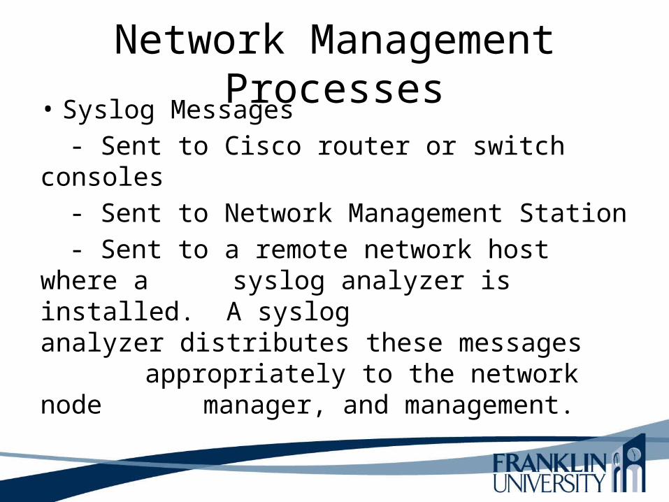
Network Management Processes• Syslog Messages
- Sent to Cisco router or switch consoles
- Sent to Network Management Station
- Sent to a remote network host where a syslog analyzer is installed. A syslog analyzer distributes these messages appropriately to the network node manager, and management.
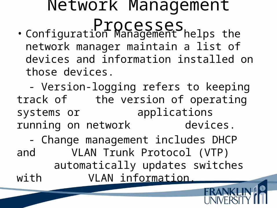
Network Management Processes• Configuration Management helps the network
manager maintain a list of devices and information installed on those devices.
- Version-logging refers to keeping track of the version of operating systems or applications running on network devices.
- Change management includes DHCP and VLAN Trunk Protocol (VTP) automatically updates switches with VLAN information.
Network Management Processes

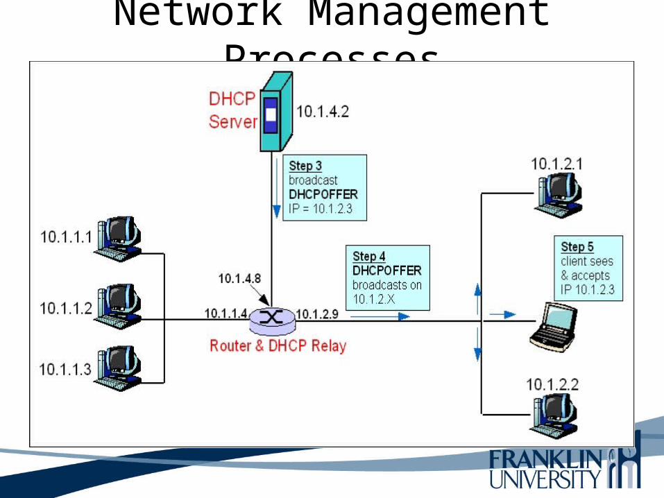
Network Management ProcessesDynamic Host Configuration Protocol
(DHCP) allows for manual and automatic assignment of IP addresses (see IETF RFC 2131 & 2132). DHCP is enacted when a new machine joins a network or an existing machine attempts to renew its IP address. DHCP is an extension of an older protocol known as the "bootstrap protocol" (BOOTP) and is backwards compatible with BOOTP. There are three methods of IP address allocation:
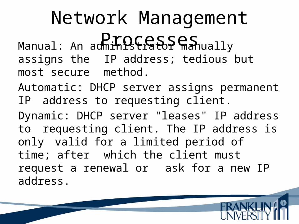
Network Management ProcessesManual: An administrator manually assigns the
IP address; tedious but most secure method.
Automatic: DHCP server assigns permanent IP address to requesting client.
Dynamic: DHCP server "leases" IP address to requesting client. The IP address is only valid for a limited period of time; after which the client must request a renewal or ask for a new IP address.

Network Management Processes
• Accounting management
- Facilitates usage-based billing. If money is not exchanged, it identifies consumption and possibly “abuse”
of network resources.

Network Management Processes• Performance management
- Facilitates measurement of network behavior and effectiveness.
-Examine network applications
- Protocol behavior
- End-to-end performance across an internetwork
- Component performance of individual links or devices.

Network Management ProcessesSecurity Management allows the network
management to maintain and distribute passwords and other authentication information. Security management should also include generating, distributing, and storing encryption keys.
– Audit logs should document logins and logouts– Attempts by individuals to change their level of
authorization.– Compressing data rather than storing less data
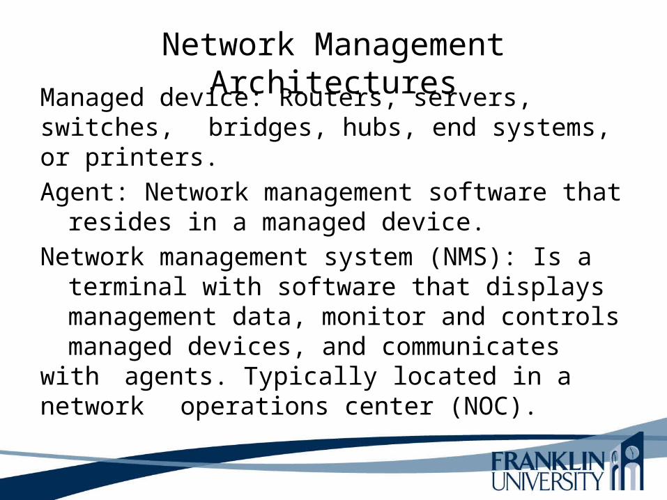
Network Management ArchitecturesManaged device: Routers, servers, switches,
bridges, hubs, end systems, or printers.
Agent: Network management software that resides in a managed device.
Network management system (NMS): Is a terminal with software that displays management data, monitor and controls managed devices, and communicates with agents. Typically located in a network operations center (NOC).

Network Management Architectures• In-band monitoring is network management
data that travels across an internetwork using the same paths as user traffic.
- Impacts ability to trouble shoot problems• Out-of-band monitoring
- More complex and expensive
- Analog lines are used for backup
- Security risks with analog links need a callback mechanisms

Network Management ArchitecturesCentralized monitoring architecture all
NMSs reside in one place of the network
Distributed monitoring means the NMSs and agents are spread out across the entire internetwork. Distributed monitoring involves a more complex network configuration and tends to be harder to manage.
Manage-of-managers (MoM) is a distributed arrangement with a central NMS. The central NMS manages the distributed locations.
Network Management Tools and Protocols
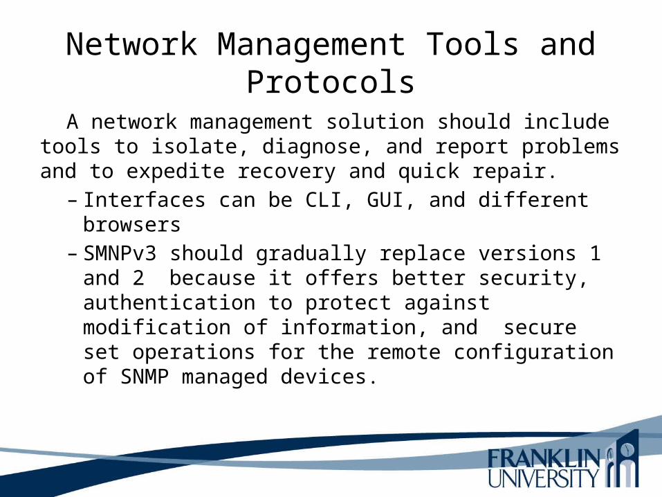
A network management solution should include tools to isolate, diagnose, and report problems and to expedite recovery and quick repair.
– Interfaces can be CLI, GUI, and different browsers– SMNPv3 should gradually replace versions 1 and
2 because it offers better security, authentication to protect against modification of information, and secure set operations for the remote configuration of SNMP managed devices.

Network Management Tools and Protocols• Management Information Bases (MIB) stores
information from local management agent on a managed device.
- Each object in a MIB has a unique identifier.
- Network management applications use the identifier to retrieve a specific object. A MIB is a structured tree and
hierarchical structure.

Network Management Tools and Protocols
The MIB structure is logically represented by a tree hierarchy. The root of the tree is unnamed and splits into three main branches: Consultative Committee for International Telegraph and Telephone (CCITT), International Organization for Standardization (ISO), and joint ISO/CCITT.

Network Management Tools and Protocols
These branches and those that fall below each category have short text strings and integers to identify them. Text strings describe object names, while integers allow computer software to create compact, encoded representations of the names. For example, the Cisco MIB variable authAddr is an object name and is denoted by number 5, which is listed at the end of its object identifier number 1.3.6.1.4.1.9.2.1.5.
Network Management Tools and Protocols
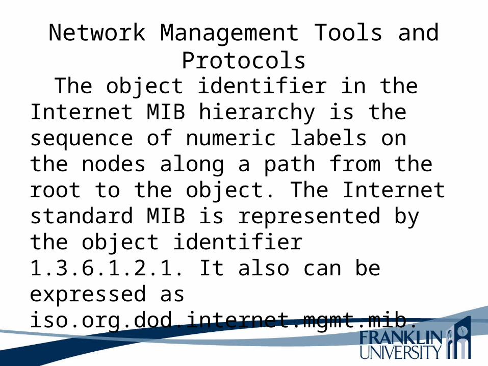
The object identifier in the Internet MIB hierarchy is the sequence of numeric labels on the nodes along a path from the root to the object. The Internet standard MIB is represented by the object identifier 1.3.6.1.2.1. It also can be expressed as iso.org.dod.internet.mgmt.mib.

Internet MIB Hierarchy

Network Management Tools and Protocols
RMON Monitoring (RMON) developed to close the gap in the standard MIBs which lacked the capability to provide statistics on the data link and physical layer parameters. The IETF developed RMON MIB to provide Ethernet traffic statistics and fault diagnosis.
- RMON collects CRC errors
- Packet-size distribution
- Number of packets in and out
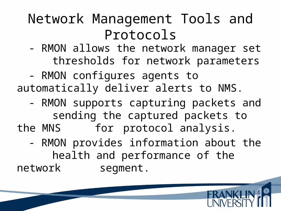
Network Management Tools and Protocols- RMON allows the network manager set
thresholds for network parameters
- RMON configures agents to automatically deliver alerts to NMS.
- RMON supports capturing packets and sending the captured packets to the MNS for protocol analysis.
- RMON provides information about the health and performance of the network segment.
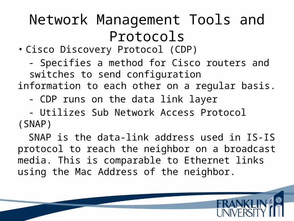
Network Management Tools and Protocols• Cisco Discovery Protocol (CDP)
- Specifies a method for Cisco routers and switches to send configuration information to each other on a regular basis.
- CDP runs on the data link layer
- Utilizes Sub Network Access Protocol (SNAP)
SNAP is the data-link address used in IS-IS protocol to reach the neighbor on a broadcast media. This is comparable to Ethernet links using the Mac Address of the neighbor.

Network Management Tools and Protocols By default, CDP announcements are sent every
60 seconds on interfaces that support Sub Network Access Protocol (SNAP) headers, including Ethernet, Frame Relay and Asynchronous Transfer Mode (ATM). Each Cisco device that supports CDP stores the information received from other devices in a table that can be viewed using the show cdp neighbors command. This table is also accessible via snmp. CDP frames are sent every 60 seconds. Switches and routers do not forward CDP frames.
Network Management Tools and Protocols
View: Cisco CPD configuration videohttp://www.youtube.com/watch?v=l9zfWyS0Bn8
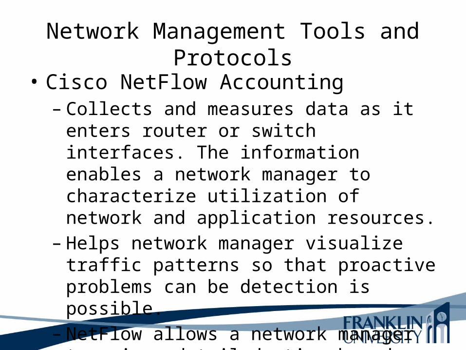
Network Management Tools and Protocols• Cisco NetFlow Accounting
– Collects and measures data as it enters router or switch interfaces. The information enables a network manager to characterize utilization of network and application resources.
– Helps network manager visualize traffic patterns so that proactive problems can be detection is possible.
– NetFlow allows a network manager to gain a detailed, time-based view of application usage.
Selecting Technologies and Devices• We now know what the network will look like.• We also know what capabilities the network
will need.• We are now ready to start picking out
technologies and devices.• Chapter 10 has guidelines for campus
networks.

Campus Network Design Steps
• Develop a cabling plant design
• Select the types of cabling• Select the data-link-layer
technologies• Select internetworking
devices• Meet with vendors
Cabling Plant Design Considerations• Campus and building cabling topologies• The types and lengths of cables between buildings• Within buildings
– The location of telecommunications closets and cross-connect rooms
– The types and lengths of cables for vertical cabling between floors
– The types and lengths of cables for horizontal cabling within floors
– The types and lengths of cables for work-area cabling going from telecommunications closets to workstations

Centralized Versus Distributed Cabling Topologies
• A centralized cabling scheme terminates most or all of the cable runs in one area of the design environment. A star topology is an example of a centralized system.
• A distributed cabling scheme terminates cable runs throughout the design environment. Ring, bus, and tree topologies are examples of distributed systems.
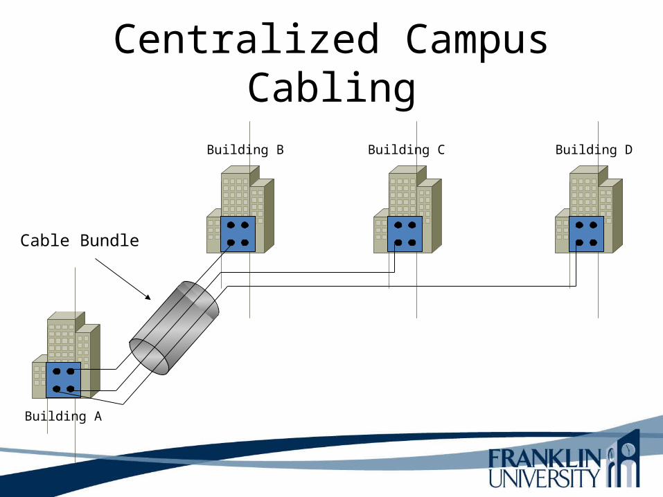
Centralized Campus Cabling
Cable Bundle
Building A
Building B Building C Building D

Distributed Campus Cabling
Building A
Building B Building C Building D
Types of Media Used in Campus Networks
• Copper media• Optical media• Wireless media

Copper Media Advantages
• Conducts electric current well• Does not rust• Can be drawn into thin wires • Easy to shape• Hard to break

Copper Media
Coaxial Twisted-Pair
Shielded Twisted-Pair (STP) Unshielded Twisted-Pair (UTP)
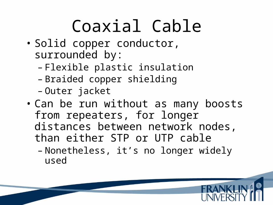
Coaxial Cable• Solid copper conductor, surrounded by:
– Flexible plastic insulation– Braided copper shielding– Outer jacket
• Can be run without as many boosts from repeaters, for longer distances between network nodes, than either STP or UTP cable– Nonetheless, it’s no longer widely used
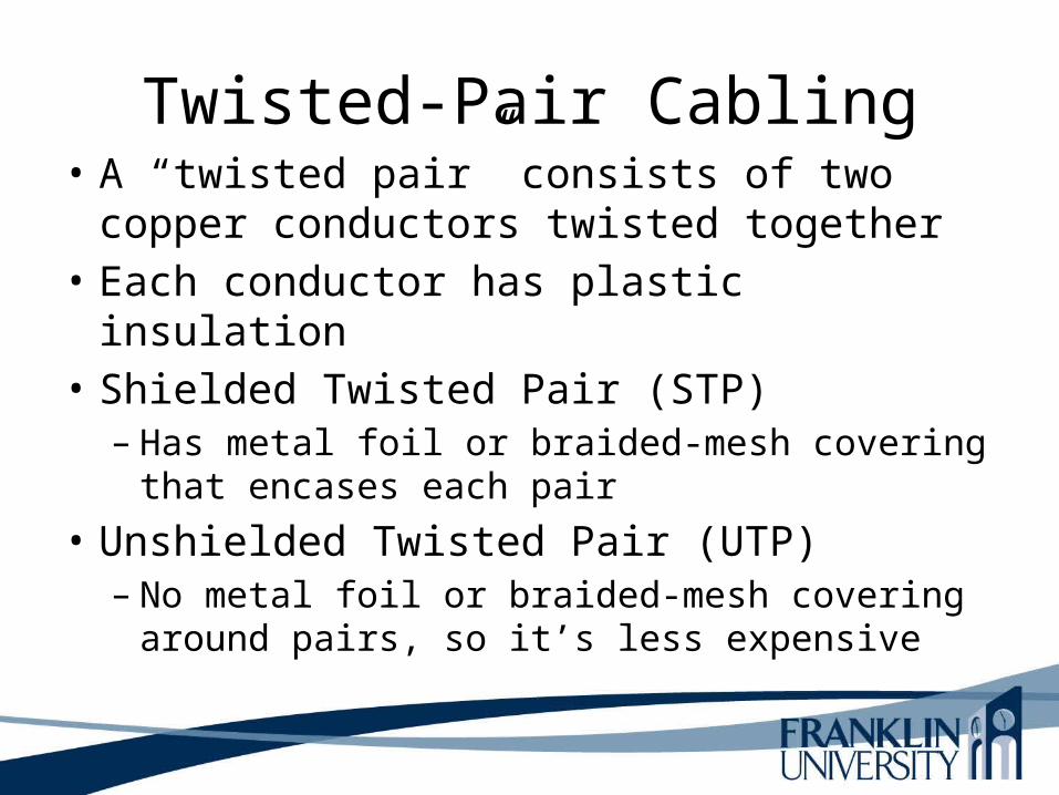
Twisted-Pair Cabling• A “twisted pair” consists of two copper
conductors twisted together• Each conductor has plastic insulation• Shielded Twisted Pair (STP)
– Has metal foil or braided-mesh covering that encases each pair
• Unshielded Twisted Pair (UTP)– No metal foil or braided-mesh covering around
pairs, so it’s less expensive

UTP Categories• Category 1. Used for voice communication• Category 2. Used for voice and data, up to 4 Mbps• Category 3. Used for data, up to 10 Mbps
– Required to have at least 3 twists per foot– Standard cable for most telephone systems– Also used in 10-Mbps Ethernet (10Base-T Ethernet)
• Category 4. Used for data, up to 16 Mbps– Must also have at least 3 twists per foot as well as other
features• Category 5. Used for data, up to 100 Mbps
– Must have 3 twists per inch! • Category 5e. Used in Gigabit Ethernet• Category 6. Used in Gigabit Ethernet and future technologies
Types of Cables
• Mode is an allowable path for light to travel down a fiber.
• Multimode fiber has multiple modes or paths that light can follow. All paths are not equal. some are longer, and the time it takes to travel down each path more time consuming.
• Single mode contains a small core diameter, has one path, supports higher bandwith rate over longer distances.
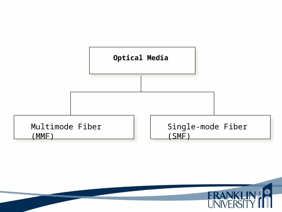
Optical Media
Multimode Fiber (MMF) Single-mode Fiber (SMF)
Copper Vs Fiber-Optic Cabling
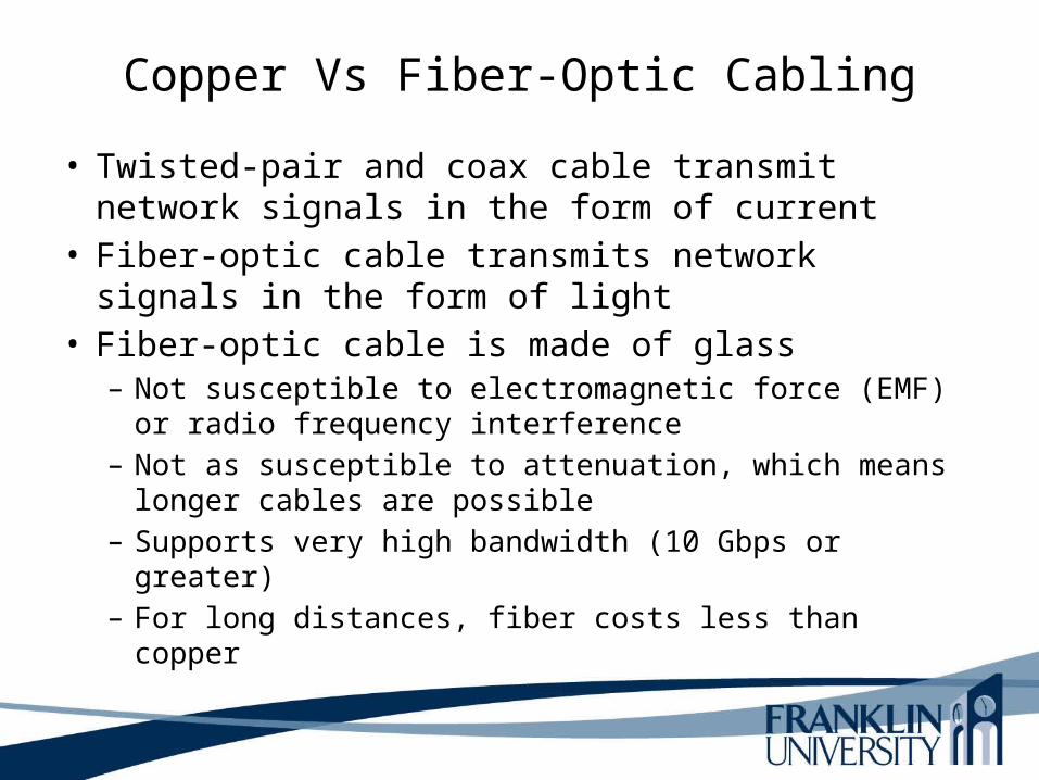
• Twisted-pair and coax cable transmit network signals in the form of current
• Fiber-optic cable transmits network signals in the form of light
• Fiber-optic cable is made of glass – Not susceptible to electromagnetic force (EMF) or radio
frequency interference– Not as susceptible to attenuation, which means longer
cables are possible– Supports very high bandwidth (10 Gbps or greater)– For long distances, fiber costs less than copper

Multimode Single-mode
• Larger core diameter• Beams of light bounce
off cladding in multiple ways
• Usually uses LED source
• Shorter distances• Less expensive
• Smaller core diameter• Less bouncing around;
single, focused beam of light
• Usually uses LASER source
• More expensive• Very long distances
LEDDefinition: A light-emitting diode (LED) is a two-lead semiconductor light source. It resembles a basic pn-junction diode, which emits light when activated

Single/Multi-Mode Fiber
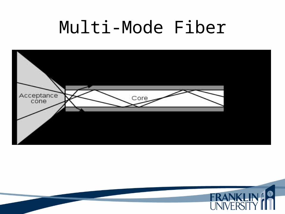
Multi-Mode Fiber

Ethernet• STP is shielded twisted pair cabling.• UTP is unshielded twisted pair cabling.
Typically found in buildings. Generally , least expensive, lowest transmission capabilities because it is subject to crosstalk, noise, and EMI (Electromagnetic Interference).
• Coax cabling was popular in the 1980s and 1990s. Not used or installed as it was in the recent past.

Electromagnetic Interference (EMI)
Ethernet• Ethernet is a physical and data link layer
standard for the transmission of frames on a LAN.
- IEEE802.3 has evolved to support UTP and fiber-optic cabling, and fast transmission speeds.
- Gigabit Ethernet is targeted for the core layer on enterprise systems.

Wireless Media
• IEEE 802.11a, b, g, n• Laser• Microwave• Cellular• Satellite
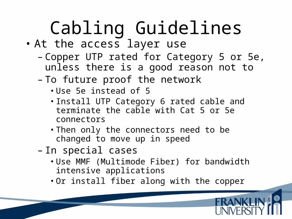
Cabling Guidelines• At the access layer use
– Copper UTP rated for Category 5 or 5e, unless there is a good reason not to
– To future proof the network• Use 5e instead of 5• Install UTP Category 6 rated cable and terminate the
cable with Cat 5 or 5e connectors• Then only the connectors need to be changed to move
up in speed
– In special cases• Use MMF (Multimode Fiber) for bandwidth intensive
applications• Or install fiber along with the copper

Cabling Guidelines• At the distribution layer use
– MMF (Multi mode fiber) if distance allows– SMF (Single mode fiber) otherwise– Unless unusual circumstances occur and cable
cannot be run, then use a wireless method– To future proof the network
• Run both MMF and SMF
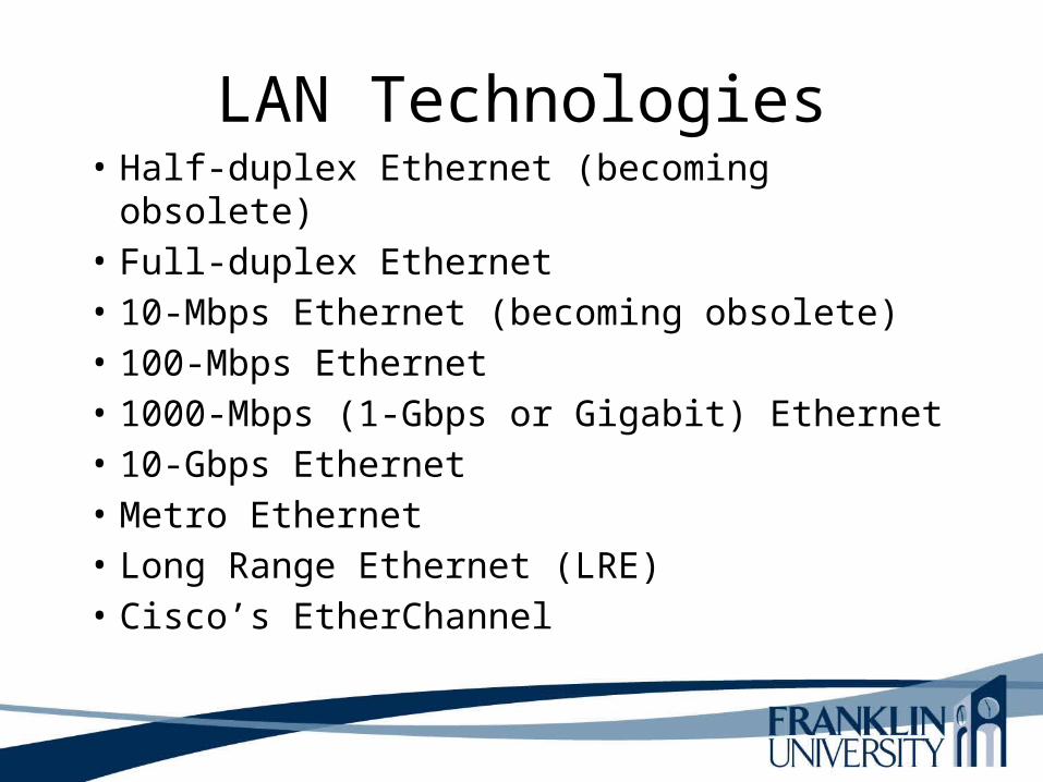
LAN Technologies• Half-duplex Ethernet (becoming obsolete)• Full-duplex Ethernet• 10-Mbps Ethernet (becoming obsolete)• 100-Mbps Ethernet • 1000-Mbps (1-Gbps or Gigabit) Ethernet• 10-Gbps Ethernet• Metro Ethernet• Long Range Ethernet (LRE)• Cisco’s EtherChannel
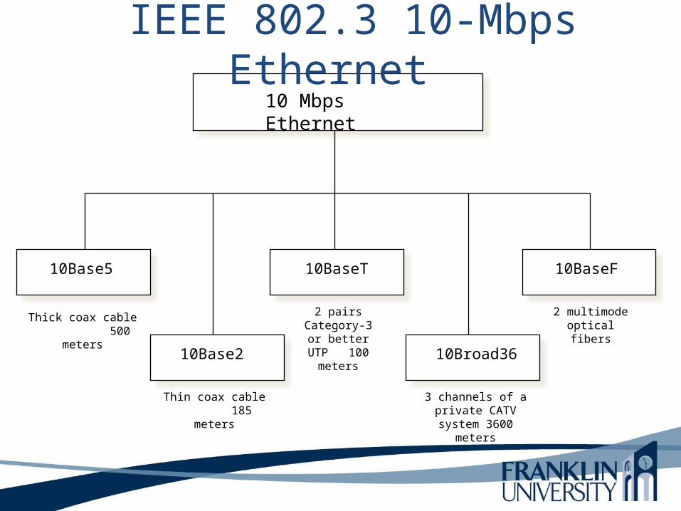
10 Mbps Ethernet
10Base5
10Base2
10BaseF
Thick coax cable 500 meters
Thin coax cable 185 meters
10BaseT
2 pairs Category-3 or better UTP 100 meters
IEEE 802.3 10-Mbps Ethernet
2 multimode optical fibers
10Broad36
3 channels of a private CATV system
3600 meters
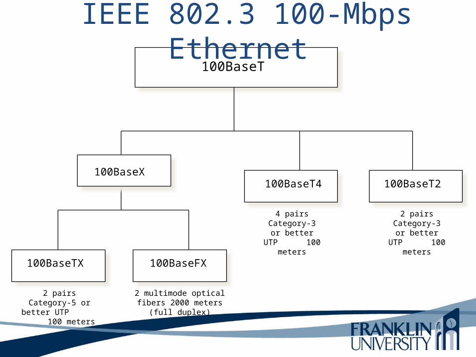
100BaseT
100BaseTX 100BaseFX
100BaseT2
2 pairs Category-5 or better UTP
100 meters
2 multimode optical fibers 2000 meters (full duplex)
100BaseT4
4 pairs Category-3 or better UTP
100 meters
IEEE 802.3 100-Mbps Ethernet
2 pairs Category-3 or better UTP
100 meters
100BaseX

1000BaseX
1000BaseSX 1000BaseLX 1000BaseT
2 multimode optical fibers using shortwave laser optics
550 meters
2 multimode or single-mode optical fibers using longwave
laser optics 550 meters multimode, 5000
meters single-mode
4 pairs Category-5 UTP100 meters
1000BaseCX
2 pairs STP 25 meters
IEEE 802.3 Gigabit Ethernet

10GBase with Fiber Cabling
10GBaseLX4 10GBaseSR 10GBaseER
Multimode or single-mode optical fibers
300 meters multimode, 10 km single-mode
Multimode optical fibers
300 meters
Single-mode optical fibers
40 km
10GBaseLR
Single-mode optical fibers
10 km
IEEE 802.3 10-Gbps Ethernet

10GBase with Copper Cabling
10GBaseCX4 SFP+ Direct Attach
XAUI 4-lane PCS15 meters
Twinax10 meters
10GBaseT
IEEE 802.3 10-Gbps Ethernet
UTP or STP100 meters

Metro Ethernet (MAN)• Service offered by providers and carriers
that traditionally had only classic WAN offerings.
• The customer can use a standard Ethernet interface to reach a MAN or WAN.
• The customer can add bandwidth as needed with a simple configuration change.

Long-Reach Ethernet• Enables the use of Ethernet over existing,
unconditioned, voice-grade copper twisted-pair cabling
• Used to connect buildings and rooms within buildings– Rural areas– Old cities where upgrading cabling is impractical– Multi-unit structures such as hotels, apartment
complexes, business complexes, and government agencies
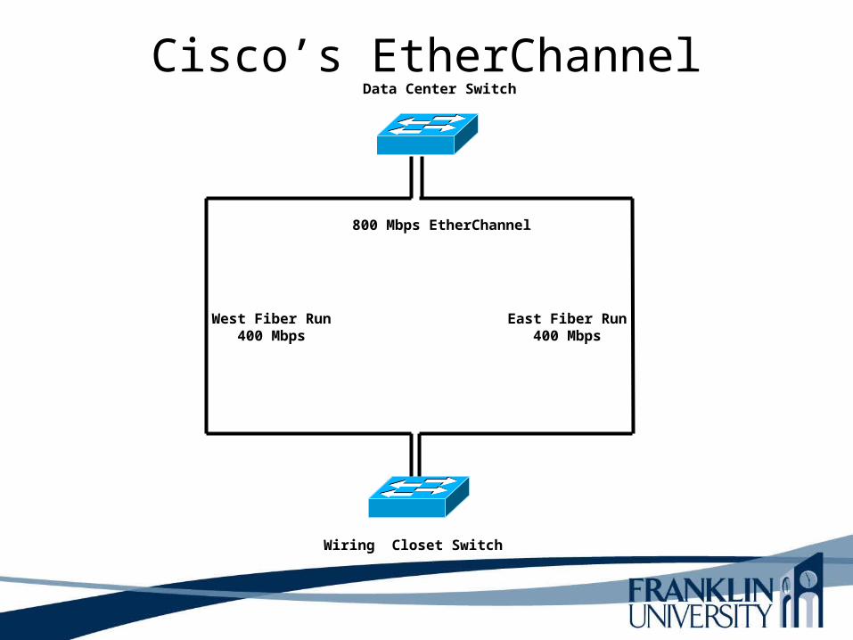
Cisco’s EtherChannelData Center Switch
Wiring Closet Switch
East Fiber Run400 Mbps
West Fiber Run400 Mbps
800 Mbps EtherChannel
Cisco’s EtherChannelEtherChannel provides incremental trunk speeds between Fast Ethernet, Gigabit Ethernet, and 10 Gigabit Ethernet. EtherChannel combines multiple Fast Ethernet up to 800Mbps, Gigabit Ethernet up to 8Gbps , and 10 Gigabit Ethernet up to 80Gbps.

Internetworking Devices for Campus Networks
• Switches• Routers• Wireless access points• Wireless bridges
Selection Criteria for Internetworking Devices
• The number of ports• Processing speed• The amount of memory• Latency when device relays data• Throughput when device relays data• LAN and WAN technologies supported• Media supported
More Selection Criteria for Internetworking Devices
• Cost• Ease of configuration and management• MTBF and MTTR• Support for hot-swappable components• Support for redundant power supplies• Quality of technical support,
documentation, and training

Summary• Once the logical design is completed, the physical
design can start• A major task during physical design is selecting
technologies and devices for campus networks– Media – Data-link layer technology– Internetworking devices
• Also, at this point, the logical topology design can be developed further by specifying cabling topologies

Review Questions• What are three fundamental media types used in
campus networks?• What selection criteria can you use to select an
Ethernet variety for your design customer?• What selection criteria can you use when purchasing
internetworking devices for your design customer?• Some people think Metro Ethernet will replace
traditional WANs. Do you agree or disagree and why?
This Week’s Outcomes
• Network Management Processes• Syslog• Security• Campus Cabling• CDP• Selection Criteria for Internetworking Devices

Due this week
• 10-1 – Concept questions 7

Next week
• Read Chapter 11 in Top-Down Network Design• 11-1 – Concept questions 8

Q & A
• Questions, comments, concerns?