Embed Size (px)
Citation preview
IT Implant System
Neo CMI Implants Merits In sinus the maxillary posterior area
IT Implant System Chart
Advantage of CMI Implant
Neo CMI Implants Body structure and Characteristics
All In One Kit Composition
Other Components
Characteristic of Drill
IT Fixture Surgical Guide
Summary of CMI Implant
Surgical System
Cover Screw
Solid Abutment
IT Abutment
Lab Analog
IT Fixture
Healing Abutment
Prosthetic Flow Chart
Excellent Solid Abutment
Impression Coping
IT Implant Component
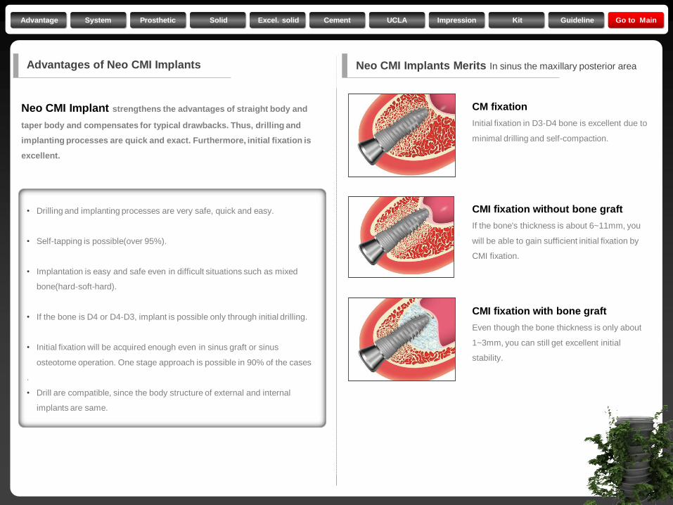
Advantages of Neo CMI Implants
Neo CMI Implant strengthens the advantages of straight body and
taper body and compensates for typical drawbacks. Thus, drilling and
implanting processes are quick and exact. Furthermore, initial fixation is
excellent.
Neo CMI Implants Merits In sinus the maxillary posterior area
• Drilling and implanting processes are very safe, quick and easy.
• Self-tapping is possible(over 95%).
• Implantation is easy and safe even in difficult situations such as mixed
bone(hard-soft-hard).
• If the bone is D4 or D4-D3, implant is possible only through initial drilling.
• Initial fixation will be acquired enough even in sinus graft or sinus
osteotome operation. One stage approach is possible in 90% of the cases
.
• Drill are compatible, since the body structure of external and internal
implants are same.
CMI fixation with bone graft
Even though the bone thickness is only about
1~3mm, you can still get excellent initial
stability.
CM fixation
Initial fixation in D3-D4 bone is excellent due to
minimal drilling and self-compaction.
CMI fixation without bone graft
If the bone's thickness is about 6~11mm, you
will be able to gain sufficient initial fixation by
CMI fixation.
Advantage System Prosthetic Solid Excel. solid Cement UCLA Impression Kit Guideline Go to Main
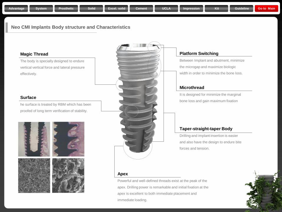
Magic Thread
The body is specially designed to endure
vertical vertical force and lateral pressure
effectively.
Surface
he surface is treated by RBM which has been
proofed of long term verification of stability.
Apex
Powerful and well-defined threads exist at the peak of the
apex. Drilling power is remarkable and initial fixation at the
apex is excellent to both immediate placement and
immediate loading.
Platform Switching
Between Implant and abutment, minimize
the microgap and maximize biologic
width in order to minimize the bone loss.
Microthread
It is designed for minimize the marginal
bone loss and gain maximum fixation
Taper-straight-taper Body
Drilling and implant insertion is easier
and also have the design to endure bite
forces and tension.
Neo CMI Implants Body structure and Characteristics
Advantage System Prosthetic Solid Excel. solid Cement UCLA Impression Kit Guideline Go to Main
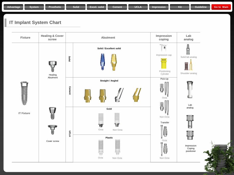
Fixture Healing & Cover
screw Abutment
Impression
coping
Lab
analog
IT Implant System Chart
IT Fixture
Solid / Excellent solid
Straight / Angled
Gold
Plastic
Pick-Up
Impression cap
Positioning
Cylinder
Non Octa
Octa Non Octa
Healing
Abutment
Cover screw
Lab
analog
Impression
Coping
positioner
UC
LA
C
em
en
t S
olid
Octa Non Octa
Transfer
Non Octa
Octa
Octa
Solid lab analog
Shoulder analog
Advantage System Prosthetic Solid Excel. solid Cement UCLA Impression Kit Guideline Go to Main
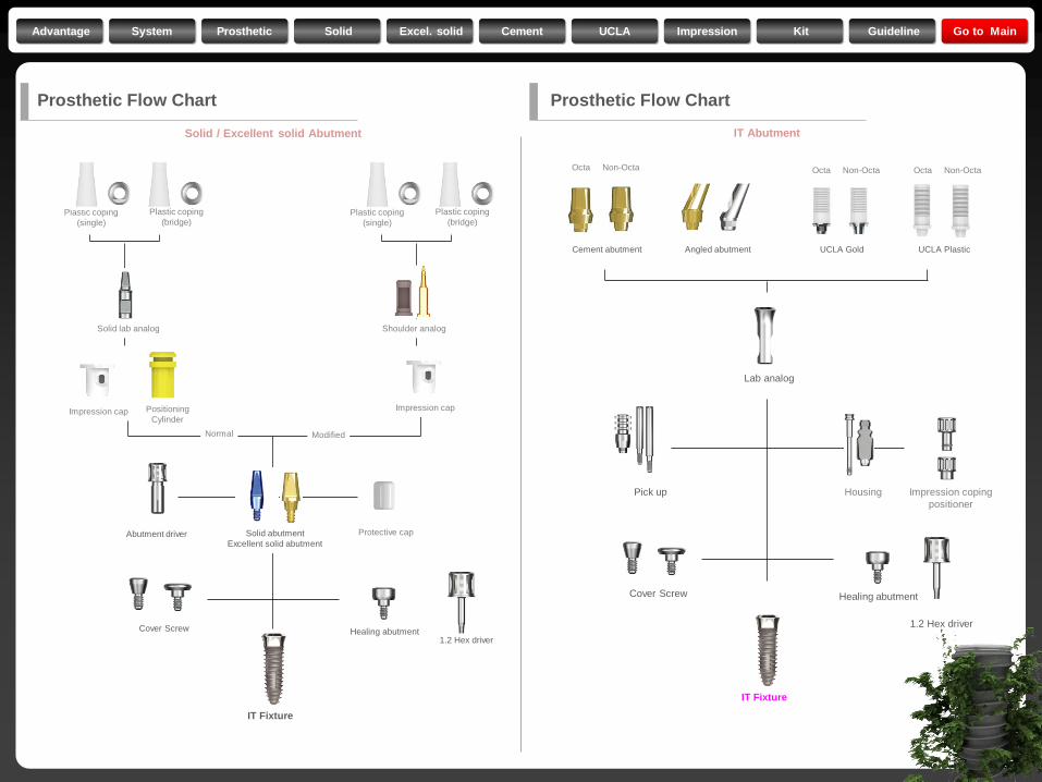
Prosthetic Flow Chart
Solid / Excellent solid Abutment
Abutment driver
Cover Screw Healing abutment 1.2 Hex driver
IT Fixture
Protective cap
Plastic coping
(single)
Plastic coping
(bridge)
Positioning
Cylinder Impression cap Impression cap
Plastic coping
(single)
Plastic coping
(bridge)
Solid abutment
Excellent solid abutment
Solid lab analog Shoulder analog
Normal Modified
IT Abutment
Lab analog
Pick up
Cover Screw Healing abutment
1.2 Hex driver
IT Fixture
Housing Impression coping
positioner
Octa Non-Octa Octa Non-Octa Octa Non-Octa
Cement abutment Angled abutment UCLA Gold UCLA Plastic
Prosthetic Flow Chart
Advantage System Prosthetic Solid Excel. solid Cement UCLA Impression Kit Guideline Go to Main
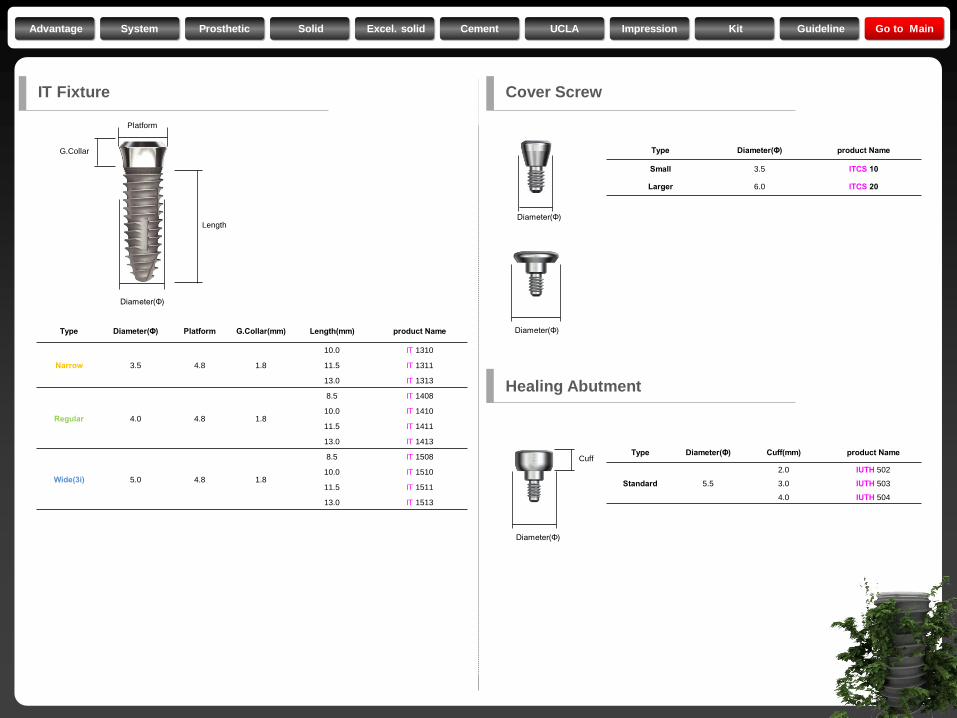
IT Fixture
Type Diameter(Φ) Platform G.Collar(mm) Length(mm) product Name
Narrow 3.5 4.8 1.8
10.0 IT 1310
11.5 IT 1311
13.0 IT 1313
Regular 4.0 4.8 1.8
8.5 IT 1408
10.0 IT 1410
11.5 IT 1411
13.0 IT 1413
Wide(3i) 5.0 4.8 1.8
8.5 IT 1508
10.0 IT 1510
11.5 IT 1511
13.0 IT 1513
Diameter(Φ)
Length
Cover Screw
Platform
G.Collar Type Diameter(Φ) product Name
Small 3.5 ITCS 10
Larger 6.0 ITCS 20
Type Diameter(Φ) Cuff(mm) product Name
Standard 5.5
2.0 IUTH 502
3.0 IUTH 503
4.0 IUTH 504
Healing Abutment
Diameter(Φ)
Diameter(Φ)
Diameter(Φ)
Cuff
Advantage System Prosthetic Solid Excel. solid Cement UCLA Impression Kit Guideline Go to Main
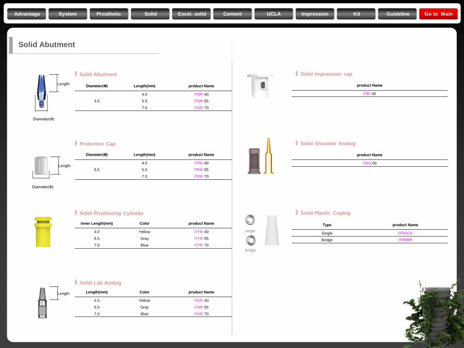
Diameter(Φ) Length(mm) product Name
3.5
4.0 ITSR 40
5.5 ITSR 55
7.0 ITSR 70
Diameter(Φ)
Length
Diameter(Φ)
Length
Length
Diameter(Φ) Length(mm) product Name
5.5
4.0 ITPR 40
5.5 ITPR 55
7.0 ITPR 70
Inner Length(mm) Color product Name
4.0 Yellow ITYR 40
5.5 Gray ITYR 55
7.0 Blue ITYR 70
Length(mm) Color product Name
4.0 Yellow ITAR 40
5.5 Gray ITAR 55
7.0 Blue ITAR 70
Solid Abutment
product Name
ITIR 00
product Name
ITAS 00
Type product Name
Single ITPRCR
Bridge ITPRBR
single
bridge
Solid Abutment
Protective Cap
Solid Positioning Cylinder
Solid Lab Analog
Solid Impression cap
Solid Shoulder Analog
Solid Plastic Coping
Advantage System Prosthetic Solid Excel. solid Cement UCLA Impression Kit Guideline Go to Main
Diameter(Φ)
Length
Diameter(Φ)
Length
Length
single
bridge
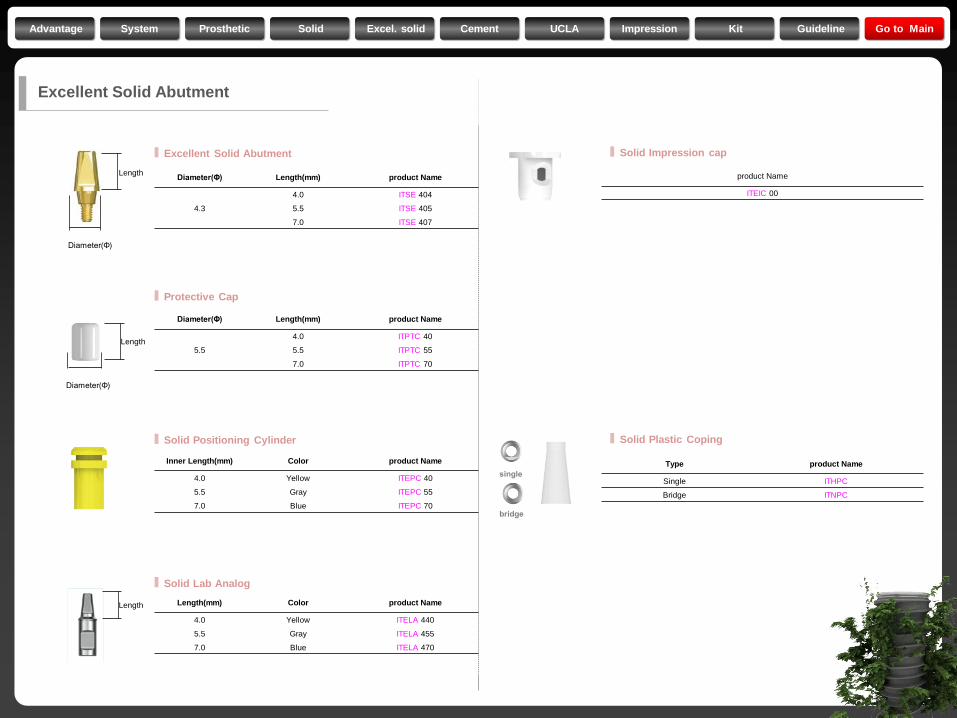
Excellent Solid Abutment
Diameter(Φ) Length(mm) product Name
4.3
4.0 ITSE 404
5.5 ITSE 405
7.0 ITSE 407
Diameter(Φ) Length(mm) product Name
5.5
4.0 ITPTC 40
5.5 ITPTC 55
7.0 ITPTC 70
Inner Length(mm) Color product Name
4.0 Yellow ITEPC 40
5.5 Gray ITEPC 55
7.0 Blue ITEPC 70
Length(mm) Color product Name
4.0 Yellow ITELA 440
5.5 Gray ITELA 455
7.0 Blue ITELA 470
Excellent Solid Abutment
product Name
ITEIC 00
Type product Name
Single ITHPC
Bridge ITNPC
Protective Cap
Solid Positioning Cylinder
Solid Lab Analog
Solid Impression cap
Solid Plastic Coping
Advantage System Prosthetic Solid Excel. solid Cement UCLA Impression Kit Guideline Go to Main
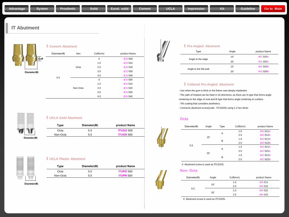
Diameter(Φ) Hex Cuff(mm) product Name
5.5
Octa
0 ICO 500
1.0 ICO 510
2.0 ICO 520
3.0 ICO 530
4.0 ICO 540
Non-Octa
0 ICN 500
1.0 ICN 510
2.0 ICN 520
3.0 ICN 530
4.0 ICN 540
Diameter(Φ)
Cuff
Type Diameter(Φ) product Name
Octa 5.5 ITUGO 500
Non-Octa 5.5 ITUGN 500
Type Diameter(Φ) product Name
Octa 5.5 ITUPO 500
Non-Octa 5.5 ITUPN 500
Diameter(Φ)
Diameter(Φ)
Type Angle product Name
Angle to the edge 15° IAO 310A
25° IAO 320A
Angle to the flat wall 15° IAO 310B
25° IAO 320B
Diameter(Φ) Angle Type Cuff(mm) product Name
5.5
15°
A 1.0 IAO 511A
2.0 IAO 512A
B 1.0 IAO 511B
2.0 IAO 512B
25°
A 1.0 IAO 521A
2.0 IAO 522A
B 1.0 IAO 521B
2.0 IAO 522B
Diameter(Φ) Angle Cuff(mm) product Name
5.5
15° 1.0 IAN 511
2.0 IAN 512
25° 1.0 IAN 521
2.0 IAN 522
- Use when the gum is thick or the fixture was deeply implanted.
- The path of implant can be fixed in 16 directions, as there are A-type that forms angle
centering on the edge of octa and B-type that forms angle centering on surface.
- TiN coating that considers aesthetics.
- Connects abutment screw(code : ITCS20S) using 1.2 hex driver
※ Abutment screw is used as ITCS20S.
※ Abutment screw is used as ITCS20S.
Octa
Non- Octa
IT Abutment
Cement Abutment
UCLA Gold Abutment
UCLA Plastic Abutment
Pre-Angled Abutment
Collared Pre-Angled Abutment
Advantage System Prosthetic Solid Excel. solid Cement UCLA Impression Kit Guideline Go to Main
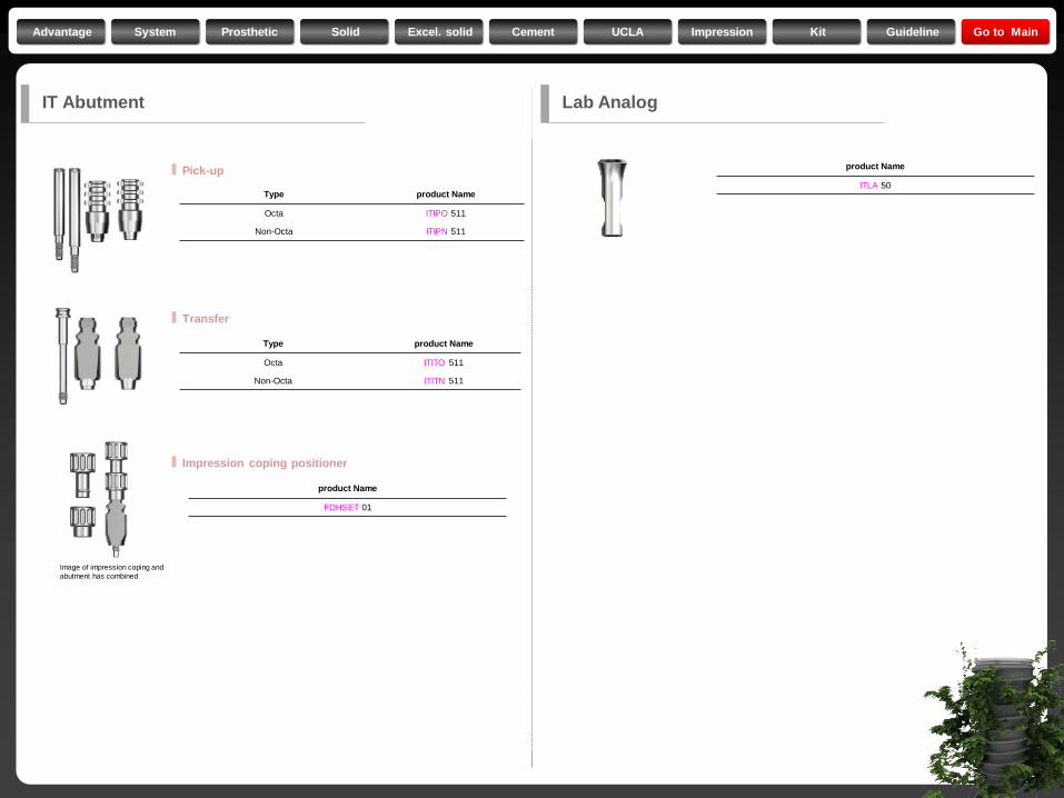
product Name
FDHSET 01
Type product Name
Octa ITIPO 511
Non-Octa ITIPN 511
Type product Name
Octa ITITO 511
Non-Octa ITITN 511
product Name
ITLA 50
Image of impression coping and
abutment has combined
IT Abutment
Pick-up
Transfer
Impression coping positioner
Lab Analog
Advantage System Prosthetic Solid Excel. solid Cement UCLA Impression Kit Guideline Go to Main
Surgical Kit
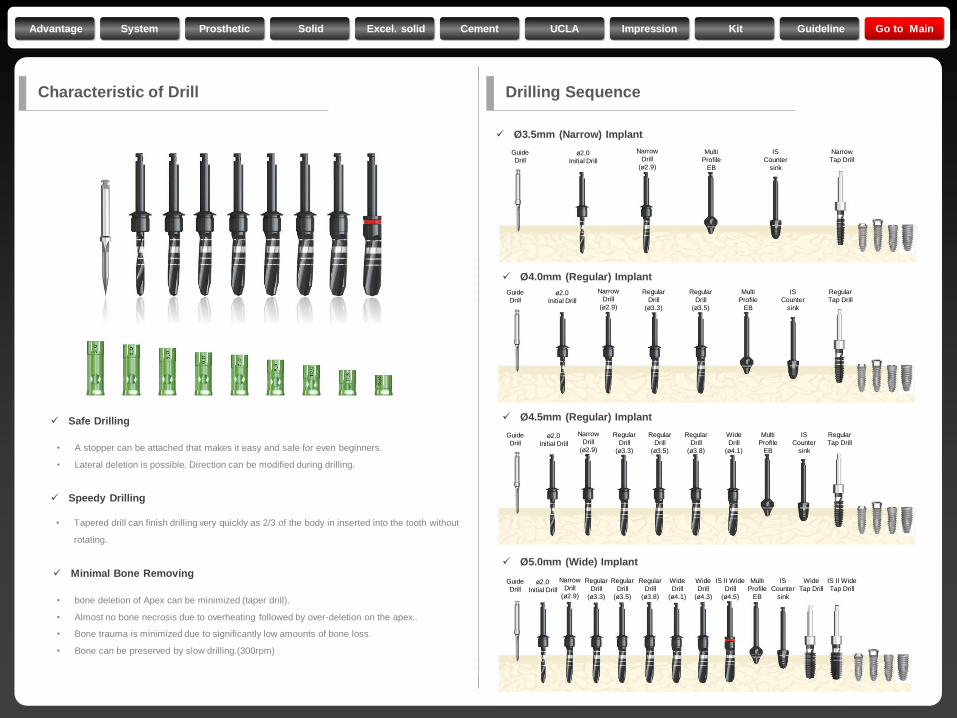
Characteristic of Drill Drilling Sequence
Safe Drilling
Speedy Drilling
Minimal Bone Removing
• A stopper can be attached that makes it easy and safe for even beginners.
• Lateral deletion is possible. Direction can be modified during drilling.
• Tapered drill can finish drilling very quickly as 2/3 of the body in inserted into the tooth without
rotating.
• bone deletion of Apex can be minimized (taper drill).
• Almost no bone necrosis due to overheating followed by over-deletion on the apex..
• Bone trauma is minimized due to significantly low amounts of bone loss.
• Bone can be preserved by slow drilling.(300rpm)
Ø 3.5mm (Narrow) Implant
Ø 4.0mm (Regular) Implant
Ø 4.5mm (Regular) Implant
Ø 5.0mm (Wide) Implant
Guide
Drill
Narrow
Drill
(ø2.9)
Regular
Drill
(ø3.8)
Wide
Drill
(ø4.1)
Regular
Drill
(ø3.3)
Regular
Drill
(ø3.5)
Wide
Drill
(ø4.3)
IS II Wide
Drill
(ø4.5)
ø2.0
Initial Drill
Multi
Profile
EB
IS
Counter
sink
Wide
Tap Drill
IS II Wide
Tap Drill
Guide
Drill
Narrow
Drill
(ø2.9)
Regular
Drill
(ø3.8)
Wide
Drill
(ø4.1)
Regular
Drill
(ø3.3)
Regular
Drill
(ø3.5)
ø2.0
Initial Drill
Multi
Profile
EB
IS
Counter
sink
Regular
Tap Drill
Guide
Drill
Narrow
Drill
(ø2.9)
Regular
Drill
(ø3.3)
Regular
Drill
(ø3.5)
ø2.0
Initial Drill
Multi
Profile
EB
IS
Counter
sink
Regular
Tap Drill
Guide
Drill
Narrow
Drill
(ø2.9)
ø2.0
Initial Drill
Multi
Profile
EB
IS
Counter
sink
Narrow
Tap Drill
Advantage System Prosthetic Solid Excel. solid Cement UCLA Impression Kit Guideline Go to Main
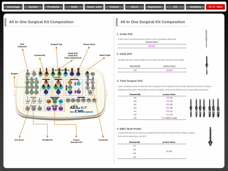
Drill
Extension
Stopper
Surgical Tap Fixture driver
Hex driver Connector Parallel Pin Fixture
Direction Pin
Countersink Guide Drill
Initial Drill
Twist surgical Drill
Multi Profile
1. Guide Drill
2. Initial Drill
3. Twist Surgical Drill
4. EB/IT Multi Profile
product Name
MICIMP
Diameter(Φ) product Name
2.0 MICIMP
Diameter(Φ) product Name
2.9 TSD 29
3.3 TSD 33
3.5 TSD 35
3.8 TSD 38
4.1 TSD 41
4.3 TSD 43
4.5 TSD 45(SI II wide)
A drill, which can point the exact place for the implantation effectively.
Straight drill that is used initially and can detect the bone density of each depth.
Laser marking is exists in each size and a stopper can be attached. Even though diameter increases, rooting or
sparking merely exists. Exact depth control is possible. It is the final drill that can be used safely at any time.
Countersink drill can be used as an option (by the density of cortical bone). Narrow, regular,
wide can be adjusted by one drill.
Diameter(Φ) product Name
3.7
MP 00 4.3
4.8
5.3
All In One Surgical Kit Composition All In One Surgical Kit Composition
Advantage System Prosthetic Solid Excel. solid Cement UCLA Impression Kit Guideline Go to Main
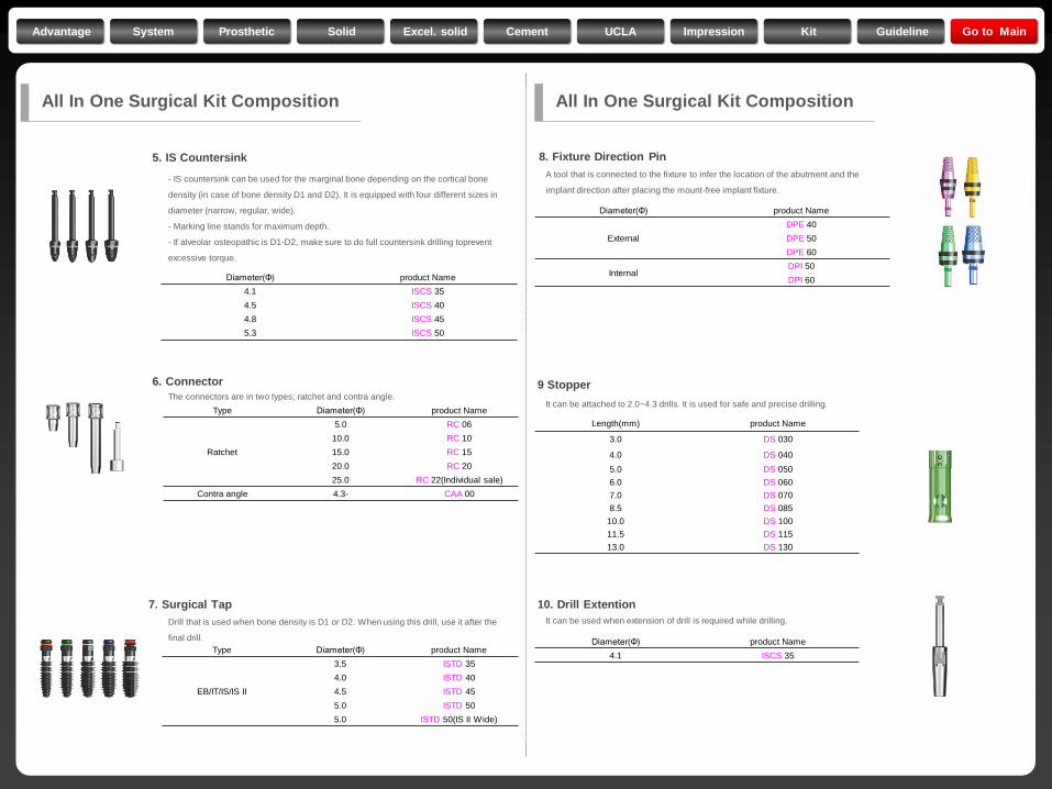
Length(mm) product Name
3.0 DS 030
4.0 DS 040
5.0 DS 050
6.0 DS 060
7.0 DS 070
8.5 DS 085
10.0 DS 100
11.5 DS 115
13.0 DS 130
Diameter(Φ) product Name
4.1 ISCS 35
4.5 ISCS 40
4.8 ISCS 45
5.3 ISCS 50
5. IS Countersink
6. Connector
7. Surgical Tap
8. Fixture Direction Pin
Type Diameter(Φ) product Name
EB/IT/IS/IS II
3.5 ISTD 35
4.0 ISTD 40
4.5 ISTD 45
5.0 ISTD 50
5.0 ISTD 50(IS II Wide)
Type Diameter(Φ) product Name
Ratchet
5.0 RC 06
10.0 RC 10
15.0 RC 15
20.0 RC 20
25.0 RC 22(Individual sale)
Contra angle 4.3- CAA 00
Diameter(Φ) product Name
External
DPE 40
DPE 50
DPE 60
Internal DPI 50
DPI 60
A tool that is connected to the fixture to infer the location of the abutment and the
implant direction after placing the mount-free implant fixture.
Drill that is used when bone density is D1 or D2. When using this drill, use it after the
final drill.
The connectors are in two types; ratchet and contra angle.
- IS countersink can be used for the marginal bone depending on the cortical bone
density (in case of bone density D1 and D2). It is equipped with four different sizes in
diameter (narrow, regular, wide).
- Marking line stands for maximum depth.
- If alveolar osteopathic is D1-D2, make sure to do full countersink drilling toprevent
excessive torque.
9 Stopper
10. Drill Extention
Diameter(Φ) product Name
4.1 ISCS 35
It can be used when extension of drill is required while drilling.
It can be attached to 2.0~4.3 drills. It is used for safe and precise drilling.
All In One Surgical Kit Composition All In One Surgical Kit Composition
Advantage System Prosthetic Solid Excel. solid Cement UCLA Impression Kit Guideline Go to Main
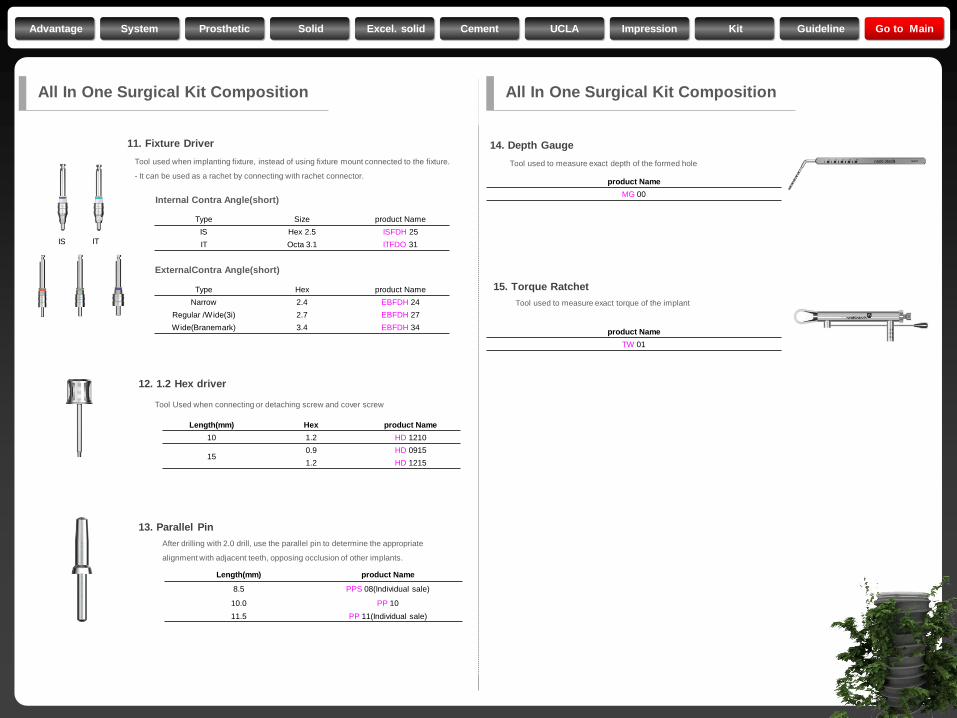
Length(mm) Hex product Name
10 1.2 HD 1210
15 0.9 HD 0915
1.2 HD 1215
Tool used to measure exact torque of the implant
Tool used to measure exact depth of the formed hole
After drilling with 2.0 drill, use the parallel pin to determine the appropriate
alignment with adjacent teeth, opposing occlusion of other implants.
Tool Used when connecting or detaching screw and cover screw
product Name
TW 01
product Name
MG 00
Length(mm) product Name
8.5 PPS 08(Individual sale)
10.0 PP 10
11.5 PP 11(Individual sale)
All In One Surgical Kit Composition
12. 1.2 Hex driver
13. Parallel Pin
14. Depth Gauge
15. Torque Ratchet
11. Fixture Driver
Tool used when implanting fixture, instead of using fixture mount connected to the fixture.
- It can be used as a rachet by connecting with rachet connector.
Type Size product Name
IS Hex 2.5 ISFDH 25
IT Octa 3.1 ITFDO 31
Type Hex product Name
Narrow 2.4 EBFDH 24
Regular /Wide(3i) 2.7 EBFDH 27
Wide(Branemark) 3.4 EBFDH 34
Internal Contra Angle(short)
ExternalContra Angle(short)
IT IS
All In One Surgical Kit Composition
Advantage System Prosthetic Solid Excel. solid Cement UCLA Impression Kit Guideline Go to Main
Type Diameter(Φ) product Name
Narrow 2.9 TSD 29
Regular 3.3 TSD 33
Wide(3i) 3.5 TSD 35
Wide(Branemark) 4.5 TSD 45(SI II wide)
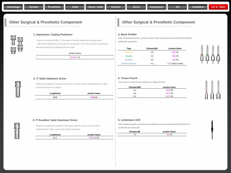
After removing the screw, a tool is used to clean-up the bone around EB fixture before
putting the prosthesis..
Tool used to cut the tissue neatly into a shape of circle.
Diameter(Φ)0 product Name
4.1 ISCS 35
4.8 ISCS 45
5.3 ISCS 50
Diameter(Φ) product Name
7.0 TD 70
Side cutting and path correction are possible as a function along with the function of
Guide drill and initial drill.
Length(mm) product Name
12.0 ITAD 0L
Length(mm) product Name
12.0 ITESDD 00
- Used to connect with EB, IT, IS system of transfer impression coping screw.
- Take each coping body and screw as a positioner. The screw can be connected as
relocating the hex by grabbing with one hand.
Match the straight line marked on the driver with the groove of solid abutment. After,
connect the fixture by rotation.
Match the straight line marked on the driver with the groove of an excellent
solid abutment. After, connect the fixture by rotation.
product Name
FDHSET 01
Other Surgical & Prosthetic Component Other Surgical & Prosthetic Component
1. Impression Coping Positioner
2. IT Solid Abutment Driver
3. IT Excellent Solid Abutment Driver
4. Bone Profiler
5. Tissue Punch
6. Lindemann Drill
Advantage System Prosthetic Solid Excel. solid Cement UCLA Impression Kit Guideline Go to Main
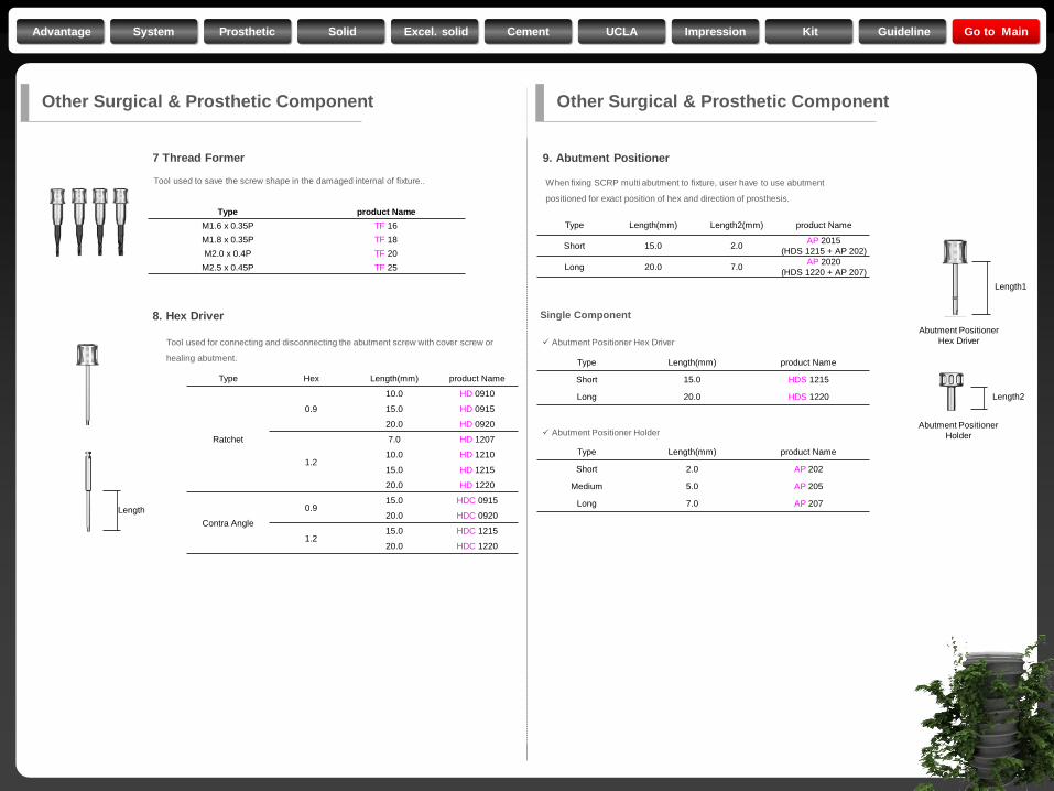
Tool used for connecting and disconnecting the abutment screw with cover screw or
healing abutment.
When fixing SCRP multi abutment to fixture, user have to use abutment
positioned for exact position of hex and direction of prosthesis.
Type Hex Length(mm) product Name
Ratchet
0.9
10.0 HD 0910
15.0 HD 0915
20.0 HD 0920
1.2
7.0 HD 1207
10.0 HD 1210
15.0 HD 1215
20.0 HD 1220
Contra Angle
0.9 15.0 HDC 0915
20.0 HDC 0920
1.2 15.0 HDC 1215
20.0 HDC 1220
Type Length(mm) Length2(mm) product Name
Short 15.0 2.0 AP 2015
(HDS 1215 + AP 202)
Long 20.0 7.0 AP 2020
(HDS 1220 + AP 207)
Type Length(mm) product Name
Short 15.0 HDS 1215
Long 20.0 HDS 1220
Type Length(mm) product Name
Short 2.0 AP 202
Medium 5.0 AP 205
Long 7.0 AP 207
Abutment Positioner Hex Driver
Abutment Positioner Holder
Length1
Length
Length2
Abutment Positioner
Hex Driver
Abutment Positioner
Holder
Other Surgical & Prosthetic Component
8. Hex Driver
9. Abutment Positioner
Single Component
Other Surgical & Prosthetic Component
Type product Name
M1.6 x 0.35P TF 16
M1.8 x 0.35P TF 18
M2.0 x 0.4P TF 20
M2.5 x 0.45P TF 25
Tool used to save the screw shape in the damaged internal of fixture..
7 Thread Former
Advantage System Prosthetic Solid Excel. solid Cement UCLA Impression Kit Guideline Go to Main
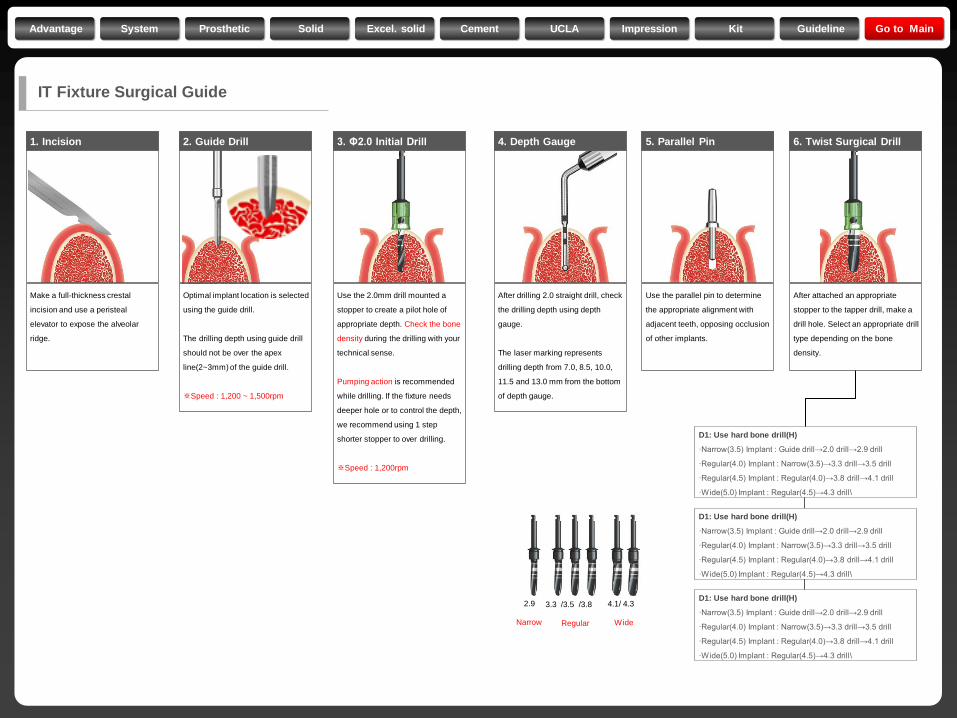
1. Incision
Make a full-thickness crestal
incision and use a peristeal
elevator to expose the alveolar
ridge.
3. Φ2.0 Initial Drill
Use the 2.0mm drill mounted a
stopper to create a pilot hole of
appropriate depth. Check the bone
density during the drilling with your
technical sense.
Pumping action is recommended
while drilling. If the fixture needs
deeper hole or to control the depth,
we recommend using 1 step
shorter stopper to over drilling.
※Speed : 1,200rpm
4. Depth Gauge
After drilling 2.0 straight drill, check
the drilling depth using depth
gauge.
The laser marking represents
drilling depth from 7.0, 8.5, 10.0,
11.5 and 13.0 mm from the bottom
of depth gauge.
5. Parallel Pin
Use the parallel pin to determine
the appropriate alignment with
adjacent teeth, opposing occlusion
of other implants.
6. Twist Surgical Drill
After attached an appropriate
stopper to the tapper drill, make a
drill hole. Select an appropriate drill
type depending on the bone
density.
2. Guide Drill
Optimal implant location is selected
using the guide drill.
The drilling depth using guide drill
should not be over the apex
line(2~3mm) of the guide drill.
※Speed : 1,200 ~ 1,500rpm
D1: Use hard bone drill(H)
·Narrow(3.5) Implant : Guide drill→2.0 drill→2.9 drill
·Regular(4.0) Implant : Narrow(3.5)→3.3 drill→3.5 drill
·Regular(4.5) Implant : Regular(4.0)→3.8 drill→4.1 drill
·Wide(5.0) Implant : Regular(4.5)→4.3 drill\
D1: Use hard bone drill(H)
·Narrow(3.5) Implant : Guide drill→2.0 drill→2.9 drill
·Regular(4.0) Implant : Narrow(3.5)→3.3 drill→3.5 drill
·Regular(4.5) Implant : Regular(4.0)→3.8 drill→4.1 drill
·Wide(5.0) Implant : Regular(4.5)→4.3 drill\
D1: Use hard bone drill(H)
·Narrow(3.5) Implant : Guide drill→2.0 drill→2.9 drill
·Regular(4.0) Implant : Narrow(3.5)→3.3 drill→3.5 drill
·Regular(4.5) Implant : Regular(4.0)→3.8 drill→4.1 drill
·Wide(5.0) Implant : Regular(4.5)→4.3 drill\
2.9 3.3 /3.5 /3.8 4.1/ 4.3
Narrow Regular Wide
IT Fixture Surgical Guide
Advantage System Prosthetic Solid Excel. solid Cement UCLA Impression Kit Guideline Go to Main
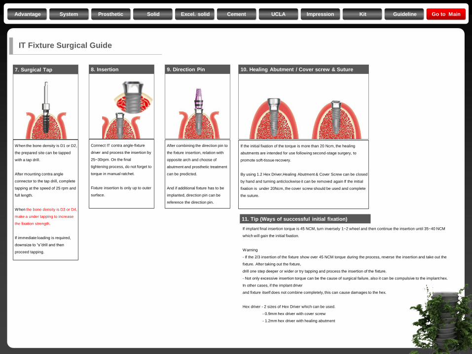
9. Direction Pin
After combining the direction pin to
the fixture insertion, relation with
opposite arch and choose of
abutment and prosthetic treatment
can be predicted.
And if additional fixture has to be
implanted, direction pin can be
reference the direction pin.
10. Healing Abutment / Cover screw & Suture
If the initial fixation of the torque is more than 20 Ncm, the healing
abutments are intended for use following second-stage surgery, to
promote soft-tissue recovery.
By using 1.2 Hex Driver,Healing Abutment & Cover Screw can be closed
by hand and turning anticlockwise it can be removed again If the initial
fixation is under 20Ncm, the cover screw should be used and complete
the suture.
11. Tip (Ways of successful initial fixation)
If implant final insertion torque is 45 NCM, turn inversely 1~2 wheel and then continue the insertion until 35~40 NCM
which will gain the initial fixation.
Warning
- If the 2/3 insertion of the fixture show over 45 NCM torque during the process, reverse the insertion and take out the
fixture. After taking out the fixture,
drill one step deeper or wider or try tapping and process the insertion of the fixture.
- Not only excessive insertion torque can be the cause of surgical failure, also it can be compulsive to the implant hex.
In other cases, if the implant driver
and fixture itself does not combine completely, this can cause damages to the hex.
Hex driver - 2 sizes of Hex Driver which can be used.
- 0.9mm hex driver with cover screw
- 1.2mm hex driver with healing abutment
7. Surgical Tap
When the bone density is D1 or D2,
the prepared site can be tapped
with a tap drill.
After mounting contra angle
connector to the tap drill, complete
tapping at the speed of 25 rpm and
full length.
When the bone density is D3 or D4,
make a under tapping to increase
the fixation strength.
If immediate loading is required,
downsize to “s”drill and then
proceed tapping.
8. Insertion
Connect IT contra angle-fixture
driver and process the insertion by
25~30rpm. On the final
tightening process, do not forget to
torque in manual ratchet.
Fixture insertion Is only up to outer
surface.
IT Fixture Surgical Guide
Advantage System Prosthetic Solid Excel. solid Cement UCLA Impression Kit Guideline Go to Main