Embed Size (px)
Citation preview

CS2204 ANALOG AND DIGITAL COMMUNICATION DEPARTMENT OF ECE
CS2204 ANALOG AND DIGITAL COMMUNICATIONQuestion Bank
UNIT I : FUNDAMENTALS OF ANALOG COMMUNICATIONPART-A:
1. What is the need for modulation? It is extremely difficult to radiate low frequency signals through earth’s
atmosphere in the form of electromagnetic energy. At low frequency, the antenna size required becomes impractical. Information signals often occupy the same frequency band. Signals from two
or more sources would interfere if they are not modulated and translated to a different frequency band.
2. With reference to AM, define modulation index (or) depth of modulation. It is defined as the ratio of peak amplitude of the message to the carrier signal.
, where E m = peak amplitude of modulating
signal voltage E c = peak amplitude of the unmodulated carrier voltage
3. A broadcast radio transmitter radiates 5 kW power when the modulation percentage is 60%. How much is the carrier power?
Pt = Pc(1+m2/2)Pc= Pt/(1+m2/2) = 5000 / (1+0.62/2) = 4237.28w
4. What is the relationship between total power in AM wave and unmodulated carrier power?
Pt = Pc(1+m2/2)Pc=unmodulated carrier powerPt=total powerm=modulation index
5. What is the relationship between total current in AM wave and unmodulated carrier current?
It =Ic(1+m2/2)Ic= carrier currentIt=total currentm=modulation index
6. An unmodulated carrier is modulated simultaneously by three modulating signals with coefficients of modulation m1 = 0.2, m2 = 0.4, m3 = 0.5. Determine the total coefficient of modulation.
mt = √m12 +m2
2 +m32 = √0.22+0.42+0.52 =0.67
7. Define amplitude Modulation.Amplitude Modulation is the process of changing the amplitude of a relatively
high frequency carrier signal in proportion with the instantaneous value of the modulating signal.8. Define Modulation index and percent modulation for an AM wave.
Modulation index is a term used to describe the amount of amplitudechange present in an AM waveform .It is also called as coefficient of modulation.
1

CS2204 ANALOG AND DIGITAL COMMUNICATION DEPARTMENT OF ECE
Mathematically modulation index is m = Em/Ec, Where m = Modulation coefficientEm = Peak change in the amplitude of the output waveform voltage.Ec = Peak amplitude of the unmodulated carrier voltage.Percent modulation gives the percentage change in the amplitude of the outputwave when the carrier is acted on by a modulating signal.
9. What is Frequency modulation? Frequency of carrier is varied in accordance with amplitude of modulating signal.
10. What is Phase modulation? Phase of carrier is varied in accordance with the amplitude of modulating signal.
11. What is Bandwidth of AM wave? Band width is difference between highest upper side frequency and lowest lower side frequency. B.W = 2fm(max).
12. What is over, under, critical modulation?If m >1, has severe distortion. This condition is Over modulation. If m=1, has
greatest output and condition is Critical modulation. If m< 1 ,has no distortion and condition is Under modulation.
13. Draw AM envelope with Vmax and Vmin?
14. With reference to FM, define modulation index.Modulation index is the ratio of frequency deviation and modulating signal frequency.m = ∆f / fm ∆f = frequency deviation in Hz
fm = modulating signal frequency in Hz 15. Define deviation ratio. It is the worst-case modulation index which is the ratio of maximum permitted frequency deviation and maximum modulating signal frequency. Deviation ratio = ∆f(max) / fm(max) 16. State Carson’s rule for determining approximate Band Width of FM signal.
Carson rule states that the bandwidth required to transmit an angle modulated wave as twice the sum of the peak frequency deviation and the highest modulating signal frequency.
Band Width = 2 [ ∆f + fm(max) ] Hz∆f = frequency deviation in Hz
fm(max) = highest modulating signal frequency in Hz17. A carrier is frequency is frequency modulated with a sinusoidal signal of 2 KHz resulting in a maximum frequency deviation of 5 KHz. Find the approximate band width of the modulated signal.
∆f = frequency deviation in Hz = 5 KHz fm(max) = highest modulating signal frequency in Hz = 2 KHz
Band Width = 2 [ ∆f + fm(max) ] Hz = 14 KHz
2

CS2204 ANALOG AND DIGITAL COMMUNICATION DEPARTMENT OF ECE
18. Determine the modulation index of a FM system with a maximum frequency deviation of 75 KHz and maximum modulating frequency of 10 KHz.
m = ∆f / fm = 75 KHz/ 10 KHz = 7.519. Distinguish between narrow band FM and wide band FM.
Narrow band FM Wide band FMFrequency deviation in carrier frequency is very small
Frequency deviation in carrier frequency is large
Band width is twice the highest modulating frequency
Band width is calculated as per Carson’s rule
20. What are the advantages of FM over AM? The amplitude of FM is constant. Hence transmitter power remains
constant in FM where as it varies in AM. Since amplitude of FM is constant, the noise interference is minimum in
FM. Any noise superimposing on modulated carrier can be removed with the help of amplitude limiter.
The depth of modulation has limitation in AM. But in FM, the depth of modulation can be increased to any value.
Since guard bands are provided in FM, there is less possibility of adjacent channel interference.
Since space waves are used for FM, the radius of propagation is limited to line of sight( LOS ) . Hence it is possible to operate several independent transmitters on same frequency with minimum interference.
Since FM uses UHF and VHF ranges, the noise interference is minimum compared to AM which uses MF and HF ranges.
21. What is the advantage and disadvantage of Angle modulation? Advantages: 1. Noise Reduction 2. Improved system fidelity 3. More effective use of power Disadvantage: 1. Require more Bandwidth 2. Use more complex circuits in both transmitter and receiver 22. Draw the FM waveform?
23. Define percent modulation?Percent modulation = [actual frequency deviation/max allowable frequency deviation] *(100)
24. A Transmitter supplies 8KW to the antenna when unmodulated. Determine the total power when amplitude modulates to 30%. Pt=Pc(1+ma
2 /2) =8x10³ (1+0.32/2)=8.36kw 25. What is the main difference b/w frequency modulation and phase modulation?
3

CS2204 ANALOG AND DIGITAL COMMUNICATION DEPARTMENT OF ECE
Frequency modulation: It is the form of angle modulation in which instantaneous frequency fI(t) is varied linearly with the base band signal m(t)
Where,fI (t)=fc+kf m(t) fc unmodulated carrier kf –Frequency sensitivity of the modulator m(t)-Base band signal Integrating above equation with respect to time and multiplying with 2 i(t)= 2fc t+2Kf m(t) dt s(t)=Ac cos i (t) s(t)= Ac cos(2fc t+2Kf m(t) dt) Phase modulation: It is that form of Angle modulation in which angle i(t) is varied linearly with the base band signal m(t) as as shown by i(t)= 2fc t+Kpm(t) s(t)=Ac cos i (t) s(t)= Ac cos(2fc t+Kpm(t)26. Determine the modulation depth of FM system with a maximum frequency deviation of 75 KHz and the maximum modulating frequency of 10 KHz =f /fM
=75 x103 /10 x103
=7.527. Write down the expression for FM signal with sinusoidal modulation Frequency modulation: It is the form of angle modulation in which instantaneous frequency fI(t) is varied linearly with the base band signal m(t) Where,fI (t)=fc+kf m(t) fc unmodulated carrier kf –Frequency sensitivity of the modulator m(t)-Base band signalIntegrating above equation with respect to time and multiplying with 2 i(t)= 2fc t+2Kf m(t) dt s(t)=Ac cos i (t) s(t)= Ac cos(2fc t+2Kf m(t) dt)28. Define instantaneous frequency deviation.The instantaneous frequency deviation is the instantaneous change in the frequency of the carrier and is defined as the first derivative of the instantaneous phase deviation.
4

CS2204 ANALOG AND DIGITAL COMMUNICATION DEPARTMENT OF ECE
PART B:1. Obtain AM wave equation and explain each term with the help of frequency spectrum and also obtain an expression for its bandwidth?In amplitude modulation, amplitude of the carrier wave is changed according to the amplitude of the signal. The technique is very much used in the transmission of radio signals.4 shows the process of amplitude modulation.
Note thatOnly amplitude of the carrier is varied while its frequency and phase remain unchanged.Whenthere is no signal, the amplitude of the carrier is equal to the unmodulated amplitude. When signal is present, the amplitude of the carrier changes in accordance with the instantaneous value of the signal.During positive cycle of the signal, the amplitude of the carrier increases to the sum of the amplitudes of the carrier and the signal (E + Em)(iv) During negative cycle of the signal, the amplitude of the carrier decreases and becomes equal to the difference of the amplitudes of the carrier and the signal.
5

CS2204 ANALOG AND DIGITAL COMMUNICATION DEPARTMENT OF ECE
6

CS2204 ANALOG AND DIGITAL COMMUNICATION DEPARTMENT OF ECE
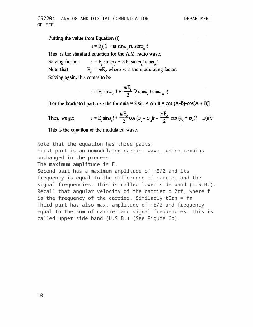
Note that the equation has three parts:First part is an unmodulated carrier wave, which remains unchanged in the process.The maximum amplitude is E.Second part has a maximum amplitude of mE/2 and its frequency is equal to the difference of carrier and the signal frequencies. This is called lower side band (L.S.B.). Recall that angular velocity of the carrier o 2rf, where f is the frequency of the carrier. Similarly tOrn = fmThird part has also max. amplitude of mE/2 and frequency equal to the sum of carrier and signal frequencies. This is called upper side band (U.S.B.) (See Figure 6b).
Figure 6 shows frequency spectrum of an A.M. wave which is equivalent to three sine waves as shown. Bandwidth (B.W.) of an A.M. wave
Hence, in amplitude modulation, the bandwidth is twice the signal frequency.2. Define modulator factor/Index/depth of modulation. Derive expression of AM wave is displaced on a CR0. Explain its significance.
Ans. (a) Modulation Factor/Index (m) : The modulation factor/index, (m) can be defined in the following ways.1. It is the ratio of maximum value of the signal to the maximum value of the carrier, i.e.,2.m Em/Eci or = mEIt is the ratio of the change in the amplitude of the carrier to its original amplitude, i.e.,4. It is the ratio of minimum amplitude to the maximum amplitude to the modulated (ratio) wave as shown below.(b) If modulation curve is displayed on a cathode ray oscilloscope (CR0), we get the curve as shown in figure 6. The modulation index m can be calculated as follow:
7

CS2204 ANALOG AND DIGITAL COMMUNICATION DEPARTMENT OF ECE
m AEC/EC3. It is the percentage change in the amplitude of the carrier, i.e.,m = 1LEC/EC)< 100Hence m can be expressed as the ratio of minimum amplitude to the maximum amplitude of the radio wave.Note:1. The vkof m lies between 0 and 1.2. T){value of m depends upon the amplitudes of the signal as well as of the carrier.Significance of m (Table 1)The modulation factor m plays a very important role in the modulation process. This will be made clear by calculating the values of m for different amplitudes of the signal and the carrier.1. Let the amplitude of signal be zero (i.e. signal is not present) and amplitude of carrier is E. In this case, the amplitude of modulated wave 0 +E = E.Change in the carrier amplitude E - E = 0. Modulation index 0/Er = 0 (No modulation)2. Let the amplitude of carrier = E and amplitude of signal = E/2.
Hence m depends on the amplitude of both the signal and the carrier.The value of m decides the strength of the modulated wave and hence that of the signal. When rn = 1(100%) the signal will be strongest, perfect and clear. In the case of overmodulation (m = 150%) the modulated wave will be clipped..off arid huge distortion will occur in the reception. Hence, the ideal value of modulation is I or 100%.
8

CS2204 ANALOG AND DIGITAL COMMUNICATION DEPARTMENT OF ECE
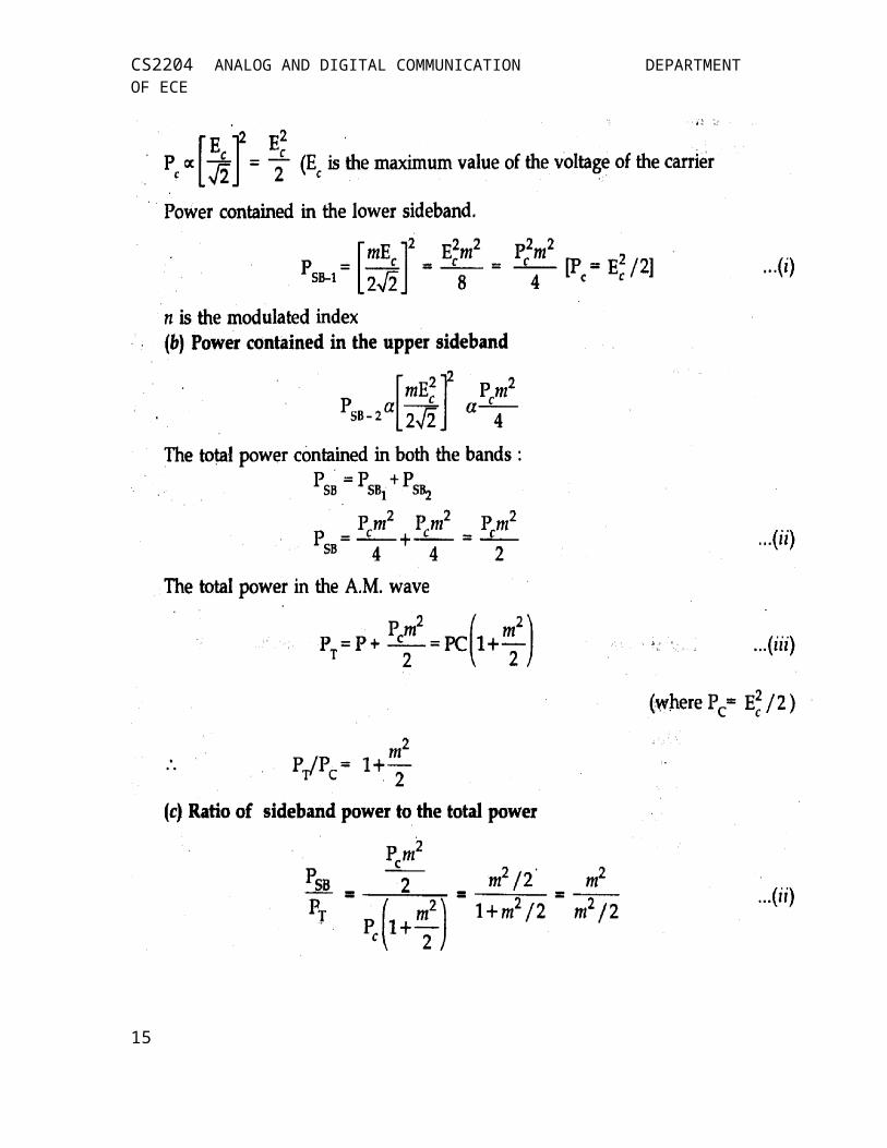
3) Derive AM power and obtain current relation between amplitude modulated and unmodulated wave. Ans. We know that the power contained in a voltage wave is proportional to the square of its amplitude (V2). Note that an A.M. wave is a voltage wave.The total power contained in an A.M. wave will be the sum of the powers contained in the three parts of the wave.Considering root mean square (R.M.S) values
Power contained in the carrier
9
CS2204 ANALOG AND DIGITAL COMMUNICATION DEPARTMENT OF ECE
10
CS2204 ANALOG AND DIGITAL COMMUNICATION DEPARTMENT OF ECE
Note that power in both the sidebands is equal and at m = 1, the sidebands contain 1/3rd (33%) power and the carrier contains 66% of the total power. Hence bands carry half the carrier power of the wave. -(d) Total power contained in two side bands = 1/3 = 33%Total power contained in each side band = 1/6 = 16.5%. VAs the signal is contained only in the sidebands, useful power is contained in side-bands. This is the reason, that we are interested only in the sidebands. The power in the sidebands go on increasing with the increase in the modulating index (m).CURRENT RELATION:Let l = Unmodulated current (carrier current)
1T = Modulated current of an A.M. wave (both in R.M.S. values) and R = Resistance through which current flows. Assume it to be the same in both the cases.
4) Write a note on evolution of SSBAM techniques.Ans. (a) In the theory of amplitude modulation (AM), we have seen that a
carrier and two sidebands (SBs) are required for AM transmission. But it is not necessary to transmit all the three signals (1 carries and 2 sidebands). The carrier or one of the sidebands may be removed (or attenuated). The SSB modulation is the fastest spreading form of analog modulation. The greatest advantage is its ability to transmit signals by using a very narrow band, width, very low power for the distances involved.
For 100% modulation (m = 1), only 113rd of the total power is present in one of the sidebands, while 2/37d power is carried by the carrier, which contains no information. Thus if the carrier and one of the sidebands is eliminated from the signal, the transmission will need only 1/6th of the total power.
The Fig. 1 shows double sideband with full carjier (DSBFC) and (b) shows
11
CS2204 ANALOG AND DIGITAL COMMUNICATION DEPARTMENT OF ECE
double sideband with supressed carrier (DSBSC) and (c) shows single sideband transmission with supressed carrier (SSBSC). It can be noted that (c) requires only half the bandwidth (BW) as required to (a) and (b).
(b) Evolution of SSBAM : The evolution of SSB amplitude modulation may be done in following steps:(i) The carrier contains no power and all the power is contained in the sidebands.(ii) Therefore there is no need to transmit carrier. V.(iii) The modulated wave contains three frequencies f f + f fc - fm(iv) Two sidebands are exact images of each other; since each is affected by changes in the modulating voltage via the exponent m EJ2. Recall that m is themodulation index and E the carrier voltage.(v) Therefore all the information may be transmitted by the use of one sideband only, as the carrier is superfluous and the other sideband is redundant.(vi) If the carrier is supressed only the two sidebands power remains and which isequal to = Pc.m2/4 about 66% saving will be done. Recall that is the carrierpower.(vii) It one of the sidebands is also supressed, the remaining power is Pc. m2/4 afurther saving of 50% power will be achieved.5) Write down the expression for FM and PM waves and draw their frequency spectrum and explain. Obtain the mathematical expressions for AM & FM modulated waves & draw the necessary waveforms in both cases
Frequency Modulation (FM) In FM transmission, the frequency of the carrier sig-nal is modulated to follow the changing voltage level amplitude of the modulating signal. The peak amplitude and phase of the carrier signal remain constant, but as the amplitude of the information signal changes, the frequency of the carrier changes correspondingly.
12

CS2204 ANALOG AND DIGITAL COMMUNICATION DEPARTMENT OF ECE
Phase Modulation: PM is used in some systems as an alternative to frequency modula-tion in PM transmission, the phase of the carrier signal is modulated to follow the chang-ing voltage level of the modulating signal. The peak amplitude and frequency of the car-rier signal remains constant, but as the amplitude of the information signal changes, the phase of the carrier changes correspondingly.
.
Unit II : DIGITAL COMMUNICATIONPART-A
1. Define ASK and FSK.ASK: A binary information signal directly modulates the amplitude of an analog
carrier.FSK: The frequency of a sinusoidal carrier is shifted between two discrete values.
2. Define bit time and baud rate.Bit time: It is the reciprocal of the bit rateBaud rate: The rate of change of a signal on the transmission medium after
encoding and modulation have occurred. Baud = 1/ts
3. Define DPSK.DPSK is an alternative form of digital modulation where the binary input
information is contained in the difference between two successive signaling elements
13

CS2204 ANALOG AND DIGITAL COMMUNICATION DEPARTMENT OF ECE
rather than absolute phase .It combines two basic operations namely ,differential encoding and phase shift keying.4. Define QPSK .QPSK: The two successive bits in a bit stream ar combined together to form a message and each message is represented by a distinct value of phase shift of the carrier. Each symbol or message contains two bits so the symbol duration Ts =2Tb.These symbols are transmitted by the same carrier at four different phase shifts as shown below.
Symbol Phase 00 01 10 11
-135 -45 135 45
5. What is a constellation diagram? Draw the constellation diagram and phasor diagram for BPSK.
Constellation diagram is used to show the relative positions of the peaks of the phasors.
Phasor diagram: constellation diagram6. Draw the phasor diagram of QPSK signal.
14
CS2204 ANALOG AND DIGITAL COMMUNICATION DEPARTMENT OF ECE
7. What is the minimum bandwidth required for an FSK system? Bandwidth required=fm-fs+ 2/tb 1/tb =fb=bit rate,fm=mark frequency,fs=space frequency 8. What is the primary advantage of DBPSK and what is its disadvantage?
Advantage: simple implementation. No carrier recovery circuit needed for detection.Disadvantage: It requires between 1 dB and 3 dB more signal to noise ratio to achieve the same BER as that of standard absolute PSK
9. What are the advantages of M-ary signaling schemes? M-ary signaling schemes transmit multiple bits at a time. Bandwidth requirement of M-ary signaling schemes is reduced.
10. Compare binary PSK with QPSK. BPSKBinary Phase Shift Keying
QPSKQuadrature Phase Shift Keying
One bit form a symbol Two bits form a symbolTwo possible symbols Four possible symbolsMinimum bandwidth required = f b
where f b is bit rateMinimum bandwidth required = f b / 2 where f b is bit rate
11. What are the advantages of QPSK as compared to BPSK? For the same bit rate, the bandwidth required by QPSK is reduced to half as
compared to BPSK. Because of reduced bandwidth, the information transmission rate of QPSK
is higher.12. What happens to the probability of error in M-ary PSK as the value of M increases?
As the value of M increases, the Euclidean distance between the symbols reduces. Hence the symbols are closer to each other. This increases the probability of error in M-ary systems.
13. What is the minimum bandwidth required for BPSK, QPSK, 8-PSK, 8-QAM and 16-QAM systems if the bit rate is 10 MBPS?
system Minimum band widthrequired if f b = bit rate
Minimum band widthrequiredif f b = 10 Mbps
BPSK f b 10 MHzQPSK f b / 2 5 MHz8 - PSK f b / 3 3.33 MHz
15

CS2204 ANALOG AND DIGITAL COMMUNICATION DEPARTMENT OF ECE
8- QAM f b / 3 3.33 MHz16 - QAM f b / 4 2.5 MHz
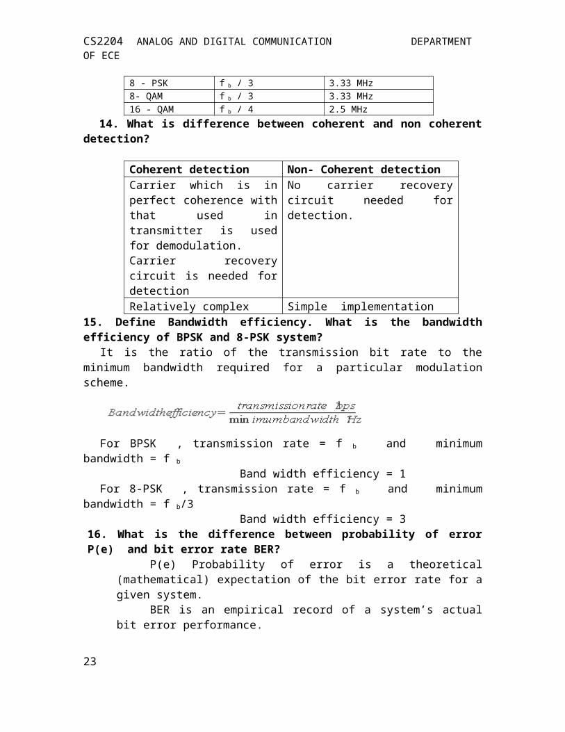
14. What is difference between coherent and non coherent detection?
Coherent detection Non- Coherent detectionCarrier which is in perfect coherence with that used in transmitter is used for demodulation.Carrier recovery circuit is needed for detection
No carrier recovery circuit needed for detection.
Relatively complex Simple implementation15. Define Bandwidth efficiency. What is the bandwidth efficiency of BPSK and 8-PSK system?
It is the ratio of the transmission bit rate to the minimum bandwidth required for a particular modulation scheme.
For BPSK , transmission rate = f b and minimum bandwidth = f b
Band width efficiency = 1For 8-PSK , transmission rate = f b and minimum bandwidth = f b/3 Band width efficiency = 3
16. What is the difference between probability of error P(e) and bit error rate BER?
P(e) Probability of error is a theoretical (mathematical) expectation of the bit error rate for a given system.
BER is an empirical record of a system’s actual bit error performance.For Example, if a system has a P(e) of 10 -5 , this mean that, you can expect one
bit error in every 100,000 bits transmitted.If a system has a BER of 10 -5 , this mean that, there was one bit error for every
100,000 bits transmitted.BER is measured and then compared to the expected probability of error to
evaluate the system’s performance.17. What is the probability of error for (i) non-coherent FSK and (ii) coherent FSK? Compare their error performance.
For a given energy per bit to noise power density ratio, probability of error for non-coherent FSK is greater than that of coherent FSK.18. Define ( Eb / N0 ) Energy per bit to Noise power density ratio.16

CS2204 ANALOG AND DIGITAL COMMUNICATION DEPARTMENT OF ECE
Energy per bit to noise power ratio is used to compare two or more digital modulation systems that uses different bit rates and modulation schemes.
It is the product of carrier to noise power ratio and the noise band width to bit rate ratio. This is equivalent to signal to noise ratio.
19. List out the advantages and disadvantages of QPSK. Advantages: low error probability, good noise immunity, baud rate is half of the bit rate Disadvantages: very complex to generate and detect the signal 20. Define carrier recovery. It is the process of extracting a phase coherent reference carrier from a received signal.
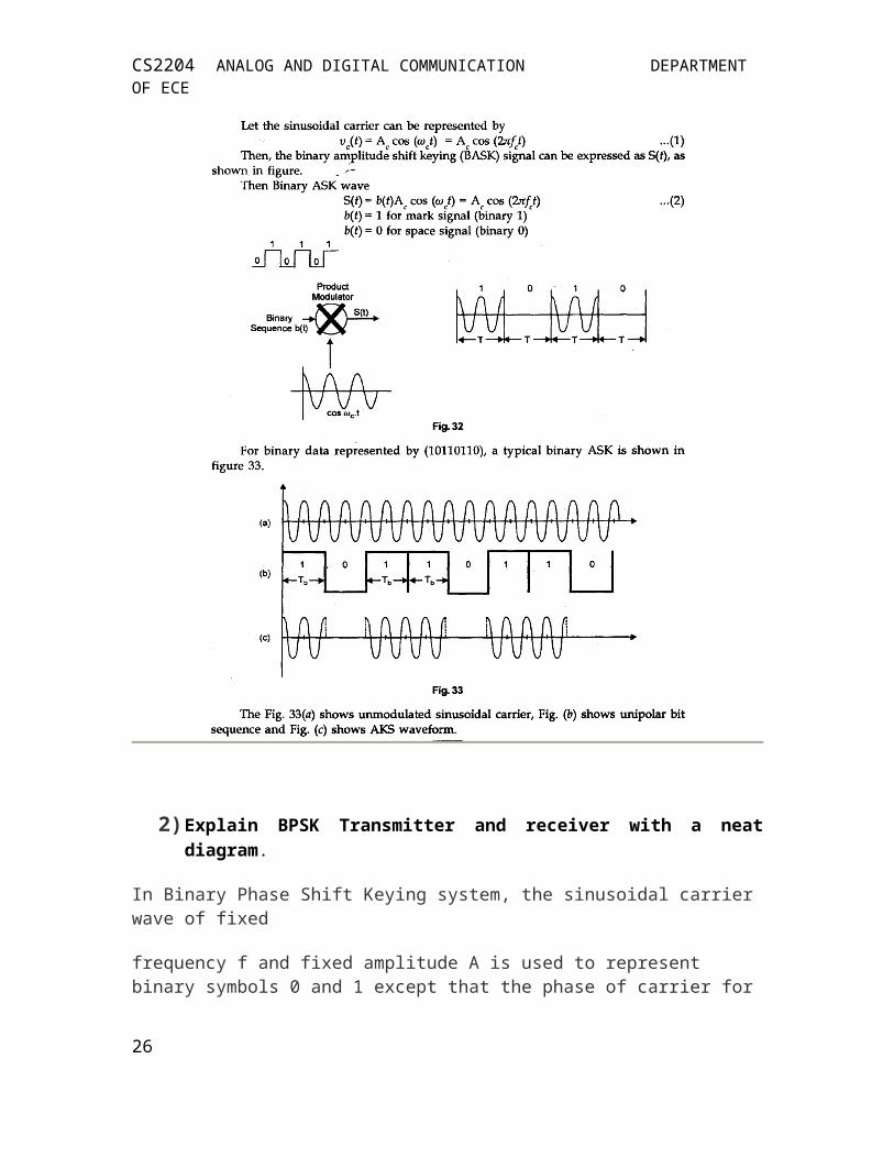
PART B 1) Explain ASK system
In Binary ASK system, two binary (1, 0) symbols are represented by two different amplitudes (A? 0) of the carrier frequency f Biiary symbol ‘1’ is represented by the presence of a constant amplitude of carrier for T, second where as other binary symbol ‘o’ is represented by the absence of the carrier for T second. This signal can be generated simply by turning on and off the carrier of a sinusoidal oscillator for the prescribed periods shown in modulating pulse train. For this, this technique is also called as on-off keying (0 0 K).
17

CS2204 ANALOG AND DIGITAL COMMUNICATION DEPARTMENT OF ECE
2) Explain BPSK Transmitter and receiver with a neat diagram.
In Binary Phase Shift Keying system, the sinusoidal carrier wave of fixed
frequency f and fixed amplitude A is used to represent binary symbols 0 and 1 except that the phase of carrier for one (1) differs by a phase angle of 180° to the phase of carrier for zero (0).
18

CS2204 ANALOG AND DIGITAL COMMUNICATION DEPARTMENT OF ECE
Here, it may be noted that unlike ASK transmission, the P5K transmission is polar. Polarity changes in the binary signal b(t) are used to produce 1800 changes in the carrier phase. This may be achieved by using double sideband, suppressed carrier modulation (DSBSC), with binary signal as a polar NRZ waveform. The carrier amplitude is multiplied by ± 1, pulsed waveform. When the binary signal b(t) is + 1, the carrier sinusoid is unchanged, and when b(t) is -1, the carrier sinusoid is changed in phase by 180°. Binary phase shift keying is also known as Phase reversal keying (PRK).
3) Explain BFSK Transmitter and receiver with a neat diagram.
Frequency shift keying is the oldest and simplest method of modulation used in modems. Two sinusoidal frequencies are used to represent binary symbols Os and is. For example, a frequency of 1070 Hz for space in data communication is used to represent binary ‘0’ and a frequency 1270 Hz for mark is used to represent binary ‘1’. These two frequencies 1070 Hz and 1270 Hz are used to represent binary signal ‘0’ and ‘1’ respectively for
19

CS2204 ANALOG AND DIGITAL COMMUNICATION DEPARTMENT OF ECE
transmission of binary data as shown in figure 34. These two frequency tones are well within the 300 to 3400 Hz band width associated with telephone system.
Another set of frequencies are required to permit simultaneous transmit and receive operation with a modem, known as full duplex operation. A frequency 2025 Hz is used to represent a binary ‘0’ or space and frequency 2225 Hz used to represent binary ‘1’ or mark. These two frequency tones are spaced far enough from the other frequencies (1070 Hz and 1270 Hz) as shown in Fig. 35. To distinguish between these
two sets of frequencies selective filters are used. The frequency set consists of 1070 and 1270 Hz tones is used for transmitting and frequency set of 2025 and 2225 Hz tones used for receiving purposes.
4) Compare the difference between ASK, FSK, PSK.
20

CS2204 ANALOG AND DIGITAL COMMUNICATION DEPARTMENT OF ECE
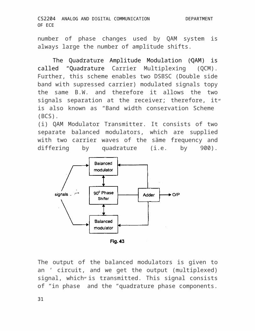
5) Explain the operation of QAM.
Quadrature Amplitude Modulation (QAM): Quadrature amplitude modula-tion is a combination of ASK and P so that a maximum contrast between each signal unit (bit, dibit, tribit and so on) is achieved.
21

CS2204 ANALOG AND DIGITAL COMMUNICATION DEPARTMENT OF ECE
The number of amplitude shifts is fewer than the number of the phase shifts. Because amplitude changes are susceptible to noise and require greater shift difference than do phase changes, the number of phase changes used by QAM system is always large the number of amplitude shifts.
The Quadrature Amplitude Modulation (QAM) is called “Quadrature Carrier Multiplexing” (QCM).Further, this scheme enables two DSBSC (Double side band with supressed carrier) modulated signals topy the same B.W. and therefore it allows the two signals separation at the receiver; therefore, it is also known as “Band width conservation Scheme” (BCS). (i) QAM Modulator Transmitter. It consists of two separate balanced modu-lators, which are supplied with two carrier waves of the säme frequency and differing by quadrature (i.e. by 900).
The output of the balanced modulators is given to an ‘ circuit, and we get the output (multiplexed) signal, which is transmitted. This signal consists of “in phase” and the “quadrature phase components.QAM detector/Receiver. The transmitted (multiplexed) signal is applied si-multaneously to two separate coherent detectors, which are supplied with two local carriers of same frequency but differing in phase by 900. The out-puts of the detectors are given to low pass filters (LPF) which gives the two original massage signals.
22
CS2204 ANALOG AND DIGITAL COMMUNICATION DEPARTMENT OF ECE
For satisfactory operation of the receiver, the phase and frequency of the lo-cal oscillators at transmission and reception should be coherent (or aligned) to each other.(b) Application. The QAM system is used exclusively for digital modulation of analog carriers in data modems (modulation-demodulation) to convey data through public telephone network (PTN). The QAM is also used for digital satellite communication systems and in colour televisions.
UNIT III : DIGITAL TRANSMISSION PART-A
1. State sampling Theorem.If a finite energy signal g(t) contains no frequency component higher than W Hz, it is completely determined by specifying its ordinates at a separation of points spaced 1/ 2W seconds apart.
2. Give the methods of Sampling1. Ideal Sampling (or) Instantaneous Sampling
23

CS2204 ANALOG AND DIGITAL COMMUNICATION DEPARTMENT OF ECE
2. Natural Sampling3. Flat-top Sampling
3. What is Aliasing or Foldover?When the continuous time signal g(t) is sampled at the rate less than Nyquist rate, frequencies higher than W takes on the identity of the low frequencies in sampled signal spectrum . This is called aliasing.
The use of a low pass reconstruction filter, with its pass band extending from –W to W will not yield an undistorted version of the original signal. Aliasing can be reduced by sampling at a rate higher than Nyquist rate.
In other words, Aliasing occurs when the signal is sampled at a rate less than Nyguist rate (2W samples/ sec). It is prevented by using
Guard BandsPre-alias Filter
4. Define Nyquist rate and Nyquist interval.According to sampling theorem, a continuous time signal can be completely
represented in its samples and recovered back if the sampling frequency is fS ≥ 2W. Here fS is sampling frequency and W is the highest frequency component of the signal.Nyquist rate: The minimum sampling rate of 2W samples per second is called Nyquist rate.i.e., fS = 2W → Nyquist rateNyquist interval: Reciprocal of 2W is called the Nyquist interval. Nyquist interval = 1/2W5. Give the practical procedure for the sampling of a signal whose spectrum is not strictly band limited.
i) Prior to sampling, a low pass pre-alias filter ( anti-alias filter) of high enough order is used to attenuate those frequency components of the signal that do not contribute significantly to the information content of the signal.
ii) The filtered signal is sampled at a rate slightly higher than the Nyquist rate 2W, where W is the cutoff frequency of the pre-alias filter.6. Define aliasing error. Give the upper bound for the aliasing error.
Let {g(n/fS)} denote the sequence obtained by sampling an arbitrary signal g(t) at the rate fS samples per second. Let gi(t) denote the signal reconstructed from this sequence by interpolation;That is, gi(t)=∑ g( ) sinc ( fSt - n)The absolute error ε = | g(t) – gi(t) | is called the aliasing error.The aliasing error is bounded as ε ≤ 2 | G(f) | df7. Given the signal m(t)=10 cos (2000π t) cos (8000 π t ) , what is the minimum sampling rate based on the low pass uniform sampling theorem?
The equation shows that m(t) is generated by multiplication of two signals. We know that cosAcosB = ½ [cos (A-B)+cos (A+B)] There fore, m(t) = (10/2) [ cos (6000π t) + cos (10000π t)]The two frequencies in m(t) are 3000 Hz and 5000 Hz and the highest frequency present in m(t) is 5000 Hz. Minimum sampling rate is 2 (5000) = 10000 samples per second.8. What is Inter symbol Interference (ISI) ?
24

CS2204 ANALOG AND DIGITAL COMMUNICATION DEPARTMENT OF ECE
ISI arises because of imperfections in the overall frequency response of the system.
When a short pulse of duration Tb seconds is transmitted through a band limited system, the frequency components constituting the input pulse are differentially attenuated and, more significantly, differentially delayed by the system. Consequently the pulse appearing at the output of the system is dispersed over an interval longer than Tb
seconds.Thus when a sequence of short pulses are transmitted through the system, one
pulse every Tb seconds, the dispersed responses originating from different symbol intervals will interfere with each other, there by resulting in ISI.
9. What is eye pattern?When the received signal in a data transmission system is applied to the vertical
deflection plates of an oscilloscope and saw tooth wave( frequency = symbol rate) is applied to the horizontal deflection plates of an oscilloscope, the resulting display is called an eye pattern. The display pattern is called an eye pattern because of its resemblance to the human eye. An eye pattern provides a great deal of information about the performance of the data transmission system. Eye pattern is particularly useful in studying ISI problem.10. List out the information provided by eye pattern about the system performance.i) The width of the eye opening defines the time interval over which the received wave can be sampled without error from ISI. The preferred time for sampling is the instant of time at which the eye is open widest.ii) The sensitivity of the system to timing error is determined by the rate of closure of the eye as the sampling time is varied.iii) The height of the eye opening , at a specified sampling time, defines the margin over noise.iv) Completely closed eye shows that the effect of ISI is severe.11. State Nyquist criterion for zero ISI.
∑ P( f – n Rb ) = Tb
Tb = bit duration in seconds ; Rb = bit rate = 1/Tb
p(t ) = received pulseP(f) = Fourier Transform of p(t)
12. What is adaptive equalization?Equalization is the process of correcting channel induced distortion. This process
is said to be adaptive when it adjusts itself continuously during data transmission by operating on the input signal.
In adaptive equalization, filters adapt themselves to the channel characteristics. That is , the filter coefficients are adjusted in such a way that the distortion in the data is reduced.13. What is PAM?
It is a process in which amplitudes of regularly spaced pulses are varied in proportion to the corresponding sample values of continuous message signal.
14. What do you mean by Aperture Effect?It is nothing but amplitude distortion occurring at PAM due to the sinc function. It is overcome by using a Equalizer whose transfer function is
25
CS2204 ANALOG AND DIGITAL COMMUNICATION DEPARTMENT OF ECE
| H(f)| = T –1 sinc(fT)15. What is PPM?
It is the process in which the position of a pulse relative to its unmodulated time of occurrence is varied in accordance with message signals.
16. What is PWM?It is the process in which the samples of message signal are used to vary the duration of individual pulses in the carrier.
17. What is Quantization and sampling?Quantization: It is the process in which the analog sample of the original signal is converted into a digital form.Sampling: It is the process in which the original analog signal is converted into a discrete time and continuous amplitude signal
18. Classify Quantizers.Uniform Quanatizer – Representation levels are uniformly spaced
Non-Uniform Quanatizer – Representation levels are non-uniformly spaced19. What is Quantization Noise?
The difference between the output analog sample and the discrete output quantized signal gives raise to an error called Quantization Noise.
20. What are the limitations of delta modulation? The major limitations of delta modulation are: a) Slope overload error
b) Granular noise21. What is Slope- Overload Distortion?
When the message signal varies steeply, the quantized approximation cannot follow the message signal and this results in slope-overload distortion. It can be reduced by increasing the step-size. To minimize the distortion, we need to have
/ Ts ≥ max | d(x(t)) / dt |22. What is Granular Noise?
When the input waveform has a flat segment, then the step-size is larger when compared to the input. Therefore the approximation hunts around the segment resulting in Granular noise. This noise can be reduced by decreasing the step-size.
23. What is meant by hunting with reference to delta modulation?
The up & down movement of the approximated signal m’ (t) above & below the input signal m (t) because of the step-wise approach during delta modulation is called hunting.24. What is the principle of adaptive delta modulation?The principle underlying ADM:
a) If successive errors are of opposite polarity, then the delta modulator is operating in its granular mode. In this case the step size is reduced.
) If successive errors are of same polarity, then the delta modulator is operating in its slope overload mode. In this case the step size is increased.
25.State the difference between DPCM and DM.
Parameter DPCM DM
26

CS2204 ANALOG AND DIGITAL COMMUNICATION DEPARTMENT OF ECE
Number of Bits
Levels, Step size.
Bandwidth of transmission channel.
Bits can be more than one but less than PCM.
Fixed numbers of levels are used.
Bandwidth required is lesser than PCM.
It can use 4, 8 or 16 bits per sample.
Step size is fixed and cannot be varied.
Lower bandwidth is required.
26. What are the advantages of digital transmission?
The advantage of digital transmission over analog transmission is noiseimmunity. Digital pulses are less susceptible than analog signals to variations caused by noise. Digital signals are better suited to processing and multiplexing than analog
signals. Digital transmission systems are more noise resistant than the analog transmission
systems. Digital systems are better suited to evaluate error performance.
27. What are the disadvantages of digital transmission?* The transmission of digitally encoded analog signals requires significantly more
bandwidth than simply transmitting the original analog signal.* Analog signal must be converted to digital codes prior to transmission and
converted back to analog form at the receiver, thus necessitating additional encoding and decoding circuitry.28. Define pulse code modulation.
In pulse code modulation, analog signal is sampled and converted to fixed length,serial binary number for transmission. The binary number varies according to the amplitude of the analog signal.29. What is the purpose of the sample and hold circuit?
The sample and hold circuit periodically samples the analog input signal and converts those samples to a multilevel PAM signal.30. Define companding Nyquist sampling rate
Companding is the process of compressing, then expanding. With companded systems, the higher amplitude analog signals are compressed prior to transmission, and then expanded at the receiver.
Nyquist sampling rate: Nyquist sampling rate states that, the minimum sampling rate is equal to twice the highest audio input frequency
PART B1) State and prove Nyquisit theorem of sampling for low pass signals.
27

CS2204 ANALOG AND DIGITAL COMMUNICATION DEPARTMENT OF ECE
Ans. (a) Sampling theorem (Nyquist Theorem) : If more no. of samples are taken, the information can be reproduced correctly. The other side is also correct, i.e., if fewer samples of one information are taken in between other information can also be sent. This is similar as in our example in which one person is reading temperature of several thermometers lesser the time the person spends reading one thermometer, more time he has left to read other thermometers, or we can say to get other information.
Here, Nyquist theorem is to help, it says : In order to convey an information completely.
The minimum sampling frequency of a pulse modulated system, should be equal to (or more than twice) the highest signal frequency. Mathematically.
Where f = Minimum sampling frequency to convey complete information.
fm = Maximum frequency component present in the information signal.
e.g. The minimum sampling frequency to transmit a pure sine wave of 2 kHz
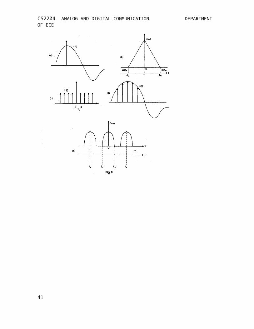
(b) Proof: The Fig. 6 (a) shows continuous time signal x(t). The fig (b) shows its frequency spectrum. The fig (c) shows impulse train. The sampling of x(t) at the rate of f5 Hz (samples) per second can be done by multiplying it with the impulse train. The impulse train consists of impulses repeating periodically every T (sampling time) seconds, where T5 = 1/f5. The Fig. (d) shows the resulted sampled signal. The fig. (e) shows spectrum of the sampled signal.
28

CS2204 ANALOG AND DIGITAL COMMUNICATION DEPARTMENT OF ECE
29

CS2204 ANALOG AND DIGITAL COMMUNICATION DEPARTMENT OF ECE
It shows that a signal where spectrum is band limited to fm Hz (i.e. the signal hasno frequency components beyond fm or it has maximum frequency fm) can be reconstructed from its samples taken at the rate off5> 2fm Hz.This proves the sampling theorem.
2) What are various pulse modulation techniques. Compare them. Ans. There are 3 pulse modulation techniques:(1) Pulse amplitude modulation (PAM)(2) Pulse width modulation (PWM)(3) Pulse modulation
3. Explain the principle of delta modulation.
30
CS2204 ANALOG AND DIGITAL COMMUNICATION DEPARTMENT OF ECE
As LOGIC 1s and 0s are received, the up-down counter is incremented or decre-mented accordingly .consequently the output of the DAC in the decoder is identi-cal to the output of the DAC is transmitter.
With delta modulation, each sample requires the transmission of only one bit; therefore, the bit rates associated with delta modulation are lower than conven-tional PCM systems.
.4. Explain various methods of analog and digital companding techniques. (a) Analog Companding.
(b) Digital Companding (i) It is the combined process of compressing and Expanding used for
improving the dynamic range of signal and also to increase the SNR of low level signals.
(ii) Analog companding and description A law and μ law companding
(iii) Digital companding with one example
. 5.Explain the procedure of PCM generation and detection with its block diagram.
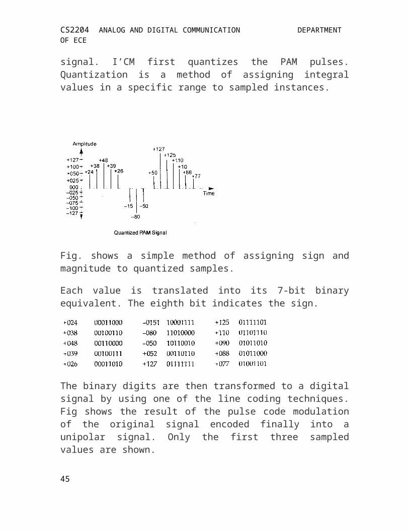
Pulse code Modulation PCM modifies the pulses created by PAM to create a completely digital signal. I’CM first quantizes the PAM pulses. Quantization is a method of assigning integral values in a specific range to sampled instances.
31

CS2204 ANALOG AND DIGITAL COMMUNICATION DEPARTMENT OF ECE
Fig. shows a simple method of assigning sign and magnitude to quantized samples.
Each value is translated into its 7-bit binary equivalent. The eighth bit indi-cates the sign.
The binary digits are then transformed to a digital signal by using one of the line coding techniques. Fig shows the result of the pulse code modulation of the original signal encoded finally into a unipolar signal. Only the first three sampled values are shown.
PCM is made up of four separate processes—
- PAM
- Quantization
- Binary encoding
- Line coding.
32
CS2204 ANALOG AND DIGITAL COMMUNICATION DEPARTMENT OF ECE
UNIT IV : DATA COMMUNICATIONS PART A
1. What is ASCII code?ASCII has been recommended by United States as ansi AND BY THE
International Standards Organization as ISO-14962.It is a 7 bit fixed length character set with 27 . With ASCII code, the LSB is designated b0 and MSB as b7.
2. Define error detection.It is defined as the process of monitoring the transmission of data and find when a
error has occurred.3. What are the error detection techniques?
Redundancy checking ----- VRC, LRC, CRC, Checksum Parity coding Exact count encoding and Echoplex.
4. What is redundancy checking? Redundancy checking is defined as the process of adding extra bits for detecting errors at the destination.
5. What is meant by CRC? CRC is a systematic code, where instead of adding bits together to achieve a desired parity, a sequence of redundant bits called CRC or CRC remainder is added to the end of the data to be transmitted. It can be written as (n,k) cyclic codes.
6. Define FCS. The group of characters forming a message is called as block or frame of data.Hence,the bit sequence for the LRC is called as block check sequence or frame check sequence(FCS).
33

CS2204 ANALOG AND DIGITAL COMMUNICATION DEPARTMENT OF ECE
7. Name the two error correction method. Retransmission and forward error correction.
8. Explain briefly about retransmission.Retransmission is the process of retransmitting the entire message to the receiver,
whenever the receiver founds that the received message is in error.If the receiver automatically calls for a retransmission of the entire message ,this process of retransmission is called as automatic repeat request(ARQ)
9. What is Forward Error Correction?It is the type of error correction scheme ,where the errors are detected and
corrected without retransmission but by adding the redundant bit to the message before transmission.
10. Define DTE and DCE.DTE is a binary digital device where the information originates or terminates.
It contains the hardware and software necessary to establish and control communications between end points within a data communication system.
DCE is used to interfaces data terminal equipment to a transmission channel.11. Define parallel interface.
Parallel interface allows the user to transfer data between two devices with eight or more bits at a same time or simultaneously. It is also called as serial by word transmission.
12. Give the characteristics of IEEE 488 bus.Logic level-TTL,number of data lines-8 and bidirectional, maximum number of
devices -15,connector-ribon.13. Define modem.
It is defined as a modulator and demodulator, which is used for connecting a computer to a telephone line.
14. Name the types of modem.Generally it is classified as synchronous and asynchronous modem.It can also be classified based on its features as low speed, high speed, medium
speed, wide band, internal or external, personal or commercial.15. Define adaptive equalizer.
It is located at the receiver section of a modem, where they provide post equalization to the received signals. This type of equalizers automatically adjusts their gain and delay characteristics to compensate for phase and amplitude impairments encountered on the communications channel.
16. Define UART and USRT.UART:Universal asynchronous receiver/transmitter is used for asynchronous
transmission of data between DTE and DCE.Asynchronous transmission means that an asynchronous data format is used and there is no clocking information transferred between DTE and DCE.
USRT:Universal synchronous receiver/transmitter is used for synchronous data transmission between DTE and DCE .It means that there is clocking information transferred between USRT and modem .
17. Give the primary functions of USRT.*To perform serial to parallel and parallel to serial conversion of data.
34

CS2204 ANALOG AND DIGITAL COMMUNICATION DEPARTMENT OF ECE
* To perform error detection by inserting and checking parity bits.*To insert and detect SYN characters.
18. What is meant by RS 232 interface? RS 232 interface specifies a 25 wire cable with DB25P compatible connector .It
is simply a cable and two connectors, the standard also specifies limitations on the voltage levels that the DTE and DCE can output onto or receive from the cable.0
19. What is meant by centronics parallel interface? Centronics parallel interface was originally designed to be used for transferring data between a microcomputer and a printer.Centronics was one of the original companies to design printers especially for desktop computers.
20. Give the primary functions of UART.*To perform serial to parallel and parallel to serial conversion of data.* To perform error detection by inserting and checking parity bits.*To insert and detect start and stop bits.
PART B1) What is X.21? What are the various signals provided by it?
Ans. X.21 Overview—X.21 is a state-driven protocol running full duplex at 9600 bps to 64 Kbps with subscriber networks. It is a circuit-switching Pro-tocol using Synchronous ASCII with odd parity to connect and disconnect a subscriber to the public- switching network.The data-transfer phase is transparent to the network. Any data can be trans-ferred through the network after Call Establishment is made successfully via the X. 21 protocol. The call control phases which are used were defined in the CCITT (now ITU) 1988 Blue Book” Recommendations X.l-X.32.
Signals provided: The signals of the X.21 interface are presented on a 15—pin connector defined by ISO Document 4903. The electrical character-istics are defined in CCITT Recommendations X.26 and X.27, which refer to CCITT Recommendations V.10 and V.11. X.21 provides eight signals Signal Ground (G): This provides reference for the logic states against the other circuits. This signal may be connected to the protective ground (earth) DTE Common Return (Ga): Used only in unbalanced-type configurations (X.26), this signal provides reference ground for receiver in the DCL inter-face. Transmit (T): This carries the binary signals which carry data from the DTE to the I)CL. this circuit can be used in data-transfer phases or in call-control phases from the DIE to DCL (during Call Connect or Call Disconnect). Receive (R): This carries the binary signals from DCE to DTE. It is used during the data transfer or Call Connect/Call Disconnect phases. Control (C): Controlled by the DTE to indicate to the DCE the meaning of the data sent on the transmit circuit. This circuit must be ON during data-35
CS2204 ANALOG AND DIGITAL COMMUNICATION DEPARTMENT OF ECE
transfer phase and can be ON or OFF during call-control phases, as defined by the protocol. Indication (I): The DCE controls this circuit to indicate to the DIE the type of data sent on the Receive line. During data phase, this circuit must be ON and it can be ON or OFF during call control, as defined by the protocol. Signal Element Timing (S): This provides the DTE or DCE with timing in-formation for sampling the Receive line or Transmit line. The DTE samples at the correct instant to determine if a binary I or 0 is being sent by the DCL. The DCE samples to accurately recover signals at the correct instant. This signal is always ON. Byte Timing (B): This circuit is normally ON and provides the DTE with 8 bit byte element timing. The circuit transitions to OFF when the Signals Ele-ment Timing circuit samples the last bit of an 8-bit byte. Call-control charac-ters must align with the 13 lead during call-control phases. During data-transfer phase, the communicating devices bilaterally agree to use the B lead to define the end of each transmitted or received byte. The C and I leads then only monitor and record changes in this condition when the 13 lead changes from OFF to ON, although the C and I leads may be altered by the transi-tions on the S lead. This lead is frequently not used.
2) What is a modem? Explain the types. Ans. A modem provides the communication interface. It transports device protocols transparently over the network through a serial interface. A mo-dem adapts the machine to communicate over various networks in order to gain access to the machine including— 1. PSTN-a wire line dial-up network2. GSM-.a wireless dial-up network3. GPRS— a wireless “always on” network. Moderns are traditionally associated with PC’s in the form of box/PC modems,However this technology is not suited to non-PC equipment or “machines”, which have specialized needs1. Size—there is little space within many embedded devices for a modem box 2. Power consumption- some devices are battery powered and need low power modems
36

CS2204 ANALOG AND DIGITAL COMMUNICATION DEPARTMENT OF ECE
3. Environment—machines can be deployed and need wide temperature range. 4. Integration— modems need to be integrated within the machine and not external Modems provide remote access to machines in the field to eliminate unnecessary site visits and provide fast access to information in the machine. However, integrating moderns.
1. Moderns are “black art” products, surrounded by complex compliance and regulatory issues. Designing your own modem solutions requires specialized skills. Using off-the-shelf modems enables designers to focus on their core application strengths and not be drawn into solving issues that are not related to core competency yielding potentially unreliable products. M2M moderns are embedded with the machine and transport higher level protocols between the machine and central location via the network. 2. Point to Point “polled” networks where proprietary or industry specific protocols to communicate with central servers. 3. TCP/IP enabled remote machines such as Embedded PC’s, where modems provide the physical network connectivity. M2M Modems are Al-command compatible at the serial inter-face to the machine and common between many modems. 4. Driven and controlled by the remote machine processor using industry standard Commands. 5. Fast time to market.
3) What are various transmission modes? What are the advantages and disadvantage of parallel and se-rial transmission?
Ans. Data transmission means movement of data which is in the form of bits between two or more digital devices. The data transmission takes place over some physical medium from one computer to the other.There are two ways of transmitting the bits. They are37

CS2204 ANALOG AND DIGITAL COMMUNICATION DEPARTMENT OF ECE
— Parallel transmission — Serial transmissionParallel Transmission In parallel transmission of data, all the bits of a byte are transmitted simultaneously on separate wires as shown.
This type of transmission requires multiple circuits for interconnecting the two devices. Parallel transmission is possible practically if the two devices are close to each other. For example parallel transmission takes place between a computer and its printer.Advantages :1. The advantage of parallel transmission is that all the data bits will be transmitted simultaneously. Therefore the time required for the transmission of an N bit words are only one clock cycle.2. The serial transmission will require N number of clock cycles for the transmission ofsame word. Due to this the clock frequency can be kept low without affect-ing thespeed of operation. For serial transmission the clock frequency cannot be low.Disadvantages :To transmit an N-bit word, we need N number of wires. Withincrease in the number of users, these wires will be too many to handle. The serialtransmission used only one wire, for connecting the transmitter to the re-ceiver. Hence,practically the serial transmission is always preferred.Serial Transmission: In serial transmission, the bits of a byte are seriallytransmitted one after the other as shown in fig.
38

CS2204 ANALOG AND DIGITAL COMMUNICATION DEPARTMENT OF ECE
The byte to be transmitted is first stored in a shift register. Then these bits are shifted from MSB to LSB bit by bit in synchronization with the clock. Bits are shifted right by one position per clock cycle. The bit which falls out of the shift register is transmitted. Hence LSB is transmitted first. For serial transmission only one wire is needed between the transmitter and the re-ceiver. Hence serial transmission is preferred for long distance data commu-nication. In serial transmission only one bit is transmitted per clock cycle. It requires a time corresponding to 8 clock cycles to transmit one byte. The time can be reduced by increasing the clock frequency. It is used for com-puter to computer communication specially long distance. Advantages of serial transmission—Communication.I. Only one wire is required2. Reduction in cost due to less number of conductors.Disadvantages1. The speed of data transfer is low.2. To increase the speed of data transfer, it is necessary to increase the clock frequency4) Explain with pin diagrams of EIA-449 interface. Ans. EIA 449 interface Standard in case of EIA 232 the data rate is re-stricted to 20kbps and the cable length to 50 feet. The EIA and ITU-T have introduced the EIA 449 standard for users who require speed and distance. Mechanical Specifications1. The mechanical specification of EIA-449 defines a combination of two connectors, one with 37 pins and with 9 pins, for a combined 46 pins as shown in Fig.
2. The functions related to secondary channel have been removed from the DB 37 connector since they are very rarely used.
39

CS2204 ANALOG AND DIGITAL COMMUNICATION DEPARTMENT OF ECE
3. The EIA separates the secondary functions out and has puts them in the second 9 pin connector (DB-9). In this way a second channel is available to systems that need it.4. To maintain compatibility with EIA-232, EIA-449 defines two categories of pins to be used in exchanging data, control and timing information.5. The category I pins are those pins whose functions are compatible with those of EIA-232. Category II pins are those that have no equivalent in EIA-232 as shown in Table 1.
Table 2 gives the pin functions of the DB-9 connector.
40
CS2204 ANALOG AND DIGITAL COMMUNICATION DEPARTMENT OF ECE
5. State and explain the various Error Detection methodsError detection uses the concept of redundancy, which means adding extra bits for detecting errors at the destination there ate three types of redundancy checks are common in data communication:(a) Parity check(h) Cyclic Redundancy check (CRC)(c) Checksum.Parity checkIn this technique, a redundant bit called a parity bit, is added to every data unit so that the total number of Is in the unit becomes even (or odd). Suppose we want to transmit 1100001. Adding the number of 1’s gives us 3, an odd number. Before transmitting, we pass the data unit through a parity generator. The parity generator counts the 1’s and appends the parity bit to the end (al in this case)In case of redundancy check method we have to append the data unit with some extra bits. These extra bits are called parity.This parity or parity hit can be even or odd.in case of even parity we have to make number of 1’s even, including the parity hit e.g. 1110001 is the data unit where the no. of l’s is already even then we will insert 0 at the next to data unit it’, 1110001. In case of odd par-ity we have to make no. of l’s odd, including the parity bit. e.g. 1111000 is the data unit, where the no. of 1’s is even then we will insert I at the next to data unit i.e. 11110001.It is a most common and powerful technique for the detection of errors. In this technique extra bits are added. But instead of repeating the entire data stream, a shorter group of bits may be appended to the end of each unit. The
41

CS2204 ANALOG AND DIGITAL COMMUNICATION DEPARTMENT OF ECE
technique is called redundancy because the extra bits are redundant to the in-formation. They are discarded as soon as the accuracy of transmission has been determined.The following fig. shows the process of using redundant bits to check the ac-curacy of data unit.
Once the data stream has been generated. It passes through a device that ana-lyzes it and adds on appropriately’ coded redundancy check. The receiver puts the entire stream through a checking function. If the received bit stream passes the checking criteria, the data portion of the data unit is accepted and redundant bits are discarded. The most common and least expensive mechanism for error detection is the parity check.Parity checking can be simple or two-dimensional.
Simple Parity CheckIn this technique, a redundant bit, called a parity bit, is added to every data unit so that the total number of Is in the unit (including the parity bit) be-comes even (or odd). Suppose we want to transmit the binary data unit 1100001 42

CS2204 ANALOG AND DIGITAL COMMUNICATION DEPARTMENT OF ECE
Transmission ModeAdding the no. of is giving us 3 an odd number. Before transmitting we pass the data unit through a parity generator. The parity generator counts the is and appends the parity bit to the end. The total no. of is now 4, an even num-ber. The system now transmits the entire expanded unit across the network link. When it reaches its destination, the receiver puts all 8 bits through an even parity checking function. If the receiver sees 11000011, it counts four is, an even number and the data unit passes. But, if instead of 11000011, the receiver sees 11001011 then when the parity checker counts the Is it gets 5 an odd number. The receiver knows that an error has been introduced into the data somewhere and therefore rejects the whole unit. Two Dimensional Parity Check A better approach is the two dimensional parity check in this method, a block of bits is organised in a table (rows and columns). First we calculate the parity bit for each data unit. Then we organise them into table. Shows in fig we have four data units shown in four rows and eight columns. We then calculate the parity hit for each column and create a new row of 8 bits. They are the parity bits for the whole block. The first parity bit in the fifth row is calculated based on all first bits, the second parity bit is calculated based on all second bits, and so on. We then attach the 8 parity bits to the original data and sent them to the receiver.
43

CS2204 ANALOG AND DIGITAL COMMUNICATION DEPARTMENT OF ECE
Cyclic Redundancy Check (CRC): Cyclic Redundancy check method is most powerful mechanism of error detecting. Unlike the parity check which is based on addition, CRC is based on binary division.In CRC, instead of adding bits to achieve a desired parity, a sequence of re-dundant bits, called the CRC or the CRC remainder, is appended to the end of a data unit so that the resulting data unit becomes exactly divisible by a second predetermined binary number. At its destination the incoming data unit is divided by the same number. If at this step there is no remainder, the data unit is assumed to be intact and is therefore accepted. A remainder indi-cates that the data unit has been damaged in transit and therefore must be re-jected.The redundancy bits used by CRC are derived by dividing the data unit by a predetermined divisor, the remainder is the CRC. A CRC must have two qualities. It must have exactly one less bit than the divisor, and appending it to the end of the data string must make the resulting bit sequence exactly di-visible by the divisor.CRC generator and checkerFirst, a string of n 0’s is appended to the data unit. The number n is less than the number of bits in the predetermined divisor, which are n + 1 bits.Second, the newly formed data unit is divided by the divisor, using a process called binary division the remainder resulting from this division is the CRC.
44
CS2204 ANALOG AND DIGITAL COMMUNICATION DEPARTMENT OF ECE
Third, the CRC of n bits derived in step 2 replaces the appended Os at the end of the data unit. The data unit arrives at the receiver data first followed by the CRC. The receiver treats the whole string as a unit and divides it by the same divisor that was used to find the CRC remainder.
If the string arrives without error, the CRC checker yields a remainder of zero and the data unit passes. If the string has been changed in transit the di-vision yields a non zero remainder and the data unit does not pass. CHECK SUM: Checksum is the third mechanism for error detection which is also based on the concept of redundancy.Check sum GeneratorIn the sender, the check sum generator subdivides the data unit into equal segments of n bits. These segments are added using ones complement arith-metic in such a way
that the total is also n bits long. That total is then complemented and ap-pended to the and o the original data unit as redundancy bits called the check
45

CS2204 ANALOG AND DIGITAL COMMUNICATION DEPARTMENT OF ECE
sum field. The extended data unit is transmitted across the network. So if the some of data segment is T, the checksum will be T. Check sum CheckerThe receiver subdivides the data unit as above and adds all segments and complements the result. If the extended data unit is intact, the total value found by adding the data segments and the check sum field should be zero If the result is not zero, the packet contains an error and the receiver rejects it. 6.State and explain the various Error Correction methods.
A mechanism that can handle correction of an error heading of error correction code categories under theThere are two methods for error correction.(1) Error correction by retransmission.(2) Forward error correction. Error Correction by Retransmission In error correction by retransmission, when an error is discovered, the re-ceiver can have the sender retransmit the entire data unit. Forward Error Correction In forward error correction (FEC), a receiver can use an error-correcting mode, which automatically corrects certain errors. In theory it is possible to correct any error automatically. Error correcting codes however are more so-phisticated than error detection codes and require more redundancy bits. e.g. To correct a single bit error in an ASCII character, the error correction code must determine which of the 7 bits has changed In this case we have to distinguish between eight different states no error, error in position 2, and so on, up to the error in position 7. To do so requires enough bits to show all eight states.At first glance, it seems that or 3-bit redundancy code should be adequate because 3 bits can show eight different states (000 to 111) and can therefore indicate the locations of eight different possibilities. To calculate the no. of redundancy bits. We should consider
Where m is the no. of bits to be transfer r stands for the no. of redundancy. By this manner.
46

CS2204 ANALOG AND DIGITAL COMMUNICATION DEPARTMENT OF ECE
There is the practical solution for this method that is “Hamming Code”. The hamming code can be applied to data units of any length and uses the relationship between data and redundancy bits.Suppose there are 7 bits ASCII codes which requires 4 redundancy bits that can be added to the end of the data unit or interspersed with the original data bits. These units are position in 1, 2, 4, arid 8 (the position is in an 11 bit se-quence that are powers of 2). We prefer these bits are r1, r2, r4 and r8.
47
CS2204 ANALOG AND DIGITAL COMMUNICATION DEPARTMENT OF ECE
UNIT V SPREAD SPECTRUM AND MULTIPLE ACCESS TECHNIQUESPART-A1. What is meant by spread spectrum?Spread spectrum is a means of transmission in which the data of interest occupies a bandwidth in excess of the minimum bandwidth necessary to send the data2. What are the applications of spread spectrum?
It is used in military communications systems. It allows the transmitter to transmit a message to a receiver without the message
being detected by a receiver for which it is not intended. It decreases the transmitted power spectral density so that it lies well below the
thermal noise level of any unfriendly receiver. It turns out not to be possible to conceal the transmission.
3. What is the primary advantage of spread spectrum communication?The primary advantage of spread spectrum communication system is its ability to
reject interference whether it is the unintentional interference of another user simultaneously attempting to transmit through the channel or the intentional interference of a hostile transmitter attempting to jam the transmission.4. Define Pseudo Noise sequence.
A Pseudo Noise (PN) sequence is coded sequence of 1s and 0s with certain autocorrelation properties.
It is periodic – a sequence of 1s and 0s repeats itself exactly with a known period
PN sequence is a noise like high frequency signal. The sequence is not truly random but it is generated by a well defined logic.
This is used in spread spectrum communication.5. What are the properties of maximum length PN sequence?
Balance property: In each period of a maximum length sequence, the number of 1s is always one more than the number of 0s.
Run property: Among the runs of 1s and 0s in each period of a maximum length sequence, one half the runs are of length one, one fourth are of length two, one eighth are of length three and so on.. as long as these fractions represent meaningful number of runs
Correlation property: The auto correlation function of a maximum length sequence is periodic and binary valued.
6. Define processing gain. What is the processing gain for DSSS?It is defined as the ratio of spreaded signal bandwidth to unspreaded signal
bandwidth.7. Define jamming margin.It is the ratio of average interference power J and the signal power Ps.It is expressed in dB as (jamming margin) dB=(processing gain)dB-10 log[Eb/No]min
where [Eb/No]min is the minimum bit energy to noise density ratio. 8. Define chip rate and chip duration.
48

CS2204 ANALOG AND DIGITAL COMMUNICATION DEPARTMENT OF ECE
Chip rate is defined as the number of chips per second. The duration of every bit in Pseudo Noise(PN) sequence is known as chip duration.9. What is the principle of frequency hopping spread spectrum? It is the process of randomly hopping the modulated data carrier from one frequency to other .The data is used to modulate a carrier, due to this the spectrum of transmitted signal sequentially spreaded rather than instantaneously.10. Define fast frequency hopping and slow frequency hopping.
Slow frequency hopping: Symbol rate RS of the MFSK signal is an integer multiple of the hop rate R h. i.e., several symbols are transmitted in each hop.
Fast frequency hopping: The hop rate R h is an integer multiple of the MFSK symbol rate RS. i.e., carrier frequency will change or hop several times during the transmission of one symbol.
11. What are the different multiple access techniques ( Fixed assignment multiple access techniques)used in wire less communication?
TDMA – Time Division Multiple Access FDMA- Frequency Division Multiple Access CDMA – Code Division Multiple Access.
12. Compare FDMA and TDMA.
FDMA - Frequency Division Multiple Access
TDMA - Time Division Multiple Access
All users access the channel by transmitting simultaneously but using disjoint frequency bands
All users occupy the same RF band width of the channel, but they transmit sequentially in time
Fixed assignment multiple access technique
Fixed assignment multiple access technique
Well suited for analog communication Well suited for digital communication13. List the merits of CDMA over TDMA.
CDMA does not require an external synchronization network which is an essential feature of TDMA.
CDMA offers a gradual degradation in performance as the number of user is increased. It is there fore relatively easy to add new users to the system.
CDMA offers an external interference rejection capability.14. What is CDMA?
CDMA – Code Division Multiple Access. In CDMA, all users transmit simultaneously and occupy the same RF bandwidth. Each user is assigned a code which perform the DSSS or FHSS modulation
15. List out any four features of TDMA. TDMA shares a single carrier frequency with several users where each user makes use of non overlapping time slots. Data transmission for users is not continuous, but occurs in burst. Because of discontinuous transmission, handoff process is much simpler for a subscriber unit . TDMA uses different time slots for transmission and reception, thus duplexers are not required.16. What is DS spread spectrum?49

CS2204 ANALOG AND DIGITAL COMMUNICATION DEPARTMENT OF ECE
DS spread spectrum is one in which the amplitude of an already modulated signal is AM modulated by a very high rate NRZ binary stream of digits.
17. Define FH spread spectrum.FH spread spectrum is an FM or FSK technique while DS is a AM or PSK technique. The signal to be FH is usually a BFSK signal although M-ary FSK, MSK or TFM can be employed.18. What is meant by pseudo random noise?The pseudo random noise is the nose which presents in the DS spread spectrum, if the DS spread spectrum signal is V(t)=g(t)S(t)=2Psd(t)cosot. Here g(t) is a pseudo random noise binary sequence having the values 1. 19. Write the advantages of FH over direct sequence spread spectrum. Processing gain is more Spread of the transmitted signal is spread sequentially rather than instantaneously Greater transmission bandwidth and more chips per bit.20.Compare SFH and FFH.
Slow frequency hopping -SFH Fast frequency hopping- FFHMore than one symbols are transmitted
More than one hops are required to transmit one symbol
Chip rate is equal to symbol rate Chip rate is equal to hop rate
Symbol rate is higher than the hop rate
Hop rate is higher than the symbol rate
Same carrier frequency is used to transmit one or more symbols
One symbol is transmitted over multiple carriers in different hops
PART B1. Explain the Direct sequence spread spectrum technique with neat diagram
In the DS SS, each bit in the original signal is represented by multiple bits in the transmitted signal using a spreading code. The spreading code spreads the signal across a wider frequency band in direct proportion to the number of bits used. Therefore, a 10-bit spreading code spreads the signal across a frequency band that is 10 times grater than a 1hit spreading code.
One technique with direct sequence spread spectrum is to combine the digi-tal information stream with the spreading code bit stream using an exclusive. OR (XOR).
The XOR obeys the following rules
50

CS2204 ANALOG AND DIGITAL COMMUNICATION DEPARTMENT OF ECE
The following fig. shows an example.
Note that an information bit of one inverts the spreading code bits in the combination, while information bit of zero causes the spreading code bits to be transmitted without inversion. The combination bit stream has the death rate of the original spreading code sequence, so it has a wider bandwidth than the information stream. In this example, the spreading code bit stream is clocked t four times the information rate.
DSSS using BPSK:
Rather than represent binary data with 1 and 0, it is more convenient for our purpose to use + I and - 1 to represent the two binary digits. In that case, a BPSK signal can be represented as:
51

CS2204 ANALOG AND DIGITAL COMMUNICATION DEPARTMENT OF ECE
2.Explain the Frequency hopping spread spectrum in detail.FHSS is a form of spread spectrum in which the signal is broadcast
over a seemingly random series of radio frequencies, hopping from frequency to frequency at fixed intervals.Types of frequency hopping are52
CS2204 ANALOG AND DIGITAL COMMUNICATION DEPARTMENT OF ECE
(I) Slow frequency hopping(2) Fast frequency hopping. Slow-frequency hoppingIn slow frequency hoping the symbol rate R5 of the MFSK signal is an inte-ger multiple of the hop rate R. That means several symbols are transmitted corresponding to each frequency hopTherefore each frequency hop several symbolsi.e. frequency hopping takes place slowly. Fast frequency hoppingIn the fast frequency hopping the hop rate R is an integer multiple of the MFSK symbol rate R. That means during the transmission of one symbol, the carrier frequency will hop several times. Therefore each symbol transmission several frequency hops. Thus- the fre-quency hopping takes place at a fast rate.A common modulation tech. used is the M-ary frequency shift Keying (MFSK). The combination of frequency hopping (FH) and MFSK is known as FH/ MFSK.Figure shows the Block diagram of frequency hopping system. For transmis-sion, binary data are fed into a modulator using some digital - to analog en-coding scheme, such as frequency shift keying (FSK) or binary phase shift keying (BPSK). A PN source serves as an index into a table of frequencies each K bit on PN source specifies one of the 2k carrier frequencies.At each successive interval a new carrier frequency is selected. This fre-quency is then modulated by the signal produced from the initial modulator to produce a new signal with the same shape.On reception, the spread spectrum signal is demodulated using the same se-quence of PN-derived frequencies and then demodulated to produce the out-put data.
53

CS2204 ANALOG AND DIGITAL COMMUNICATION DEPARTMENT OF ECE
3)Explain difference between slow frequency hopping and Fast fre-quency hoping?
54

CS2204 ANALOG AND DIGITAL COMMUNICATION DEPARTMENT OF ECE
4) Explain CDMA system with its features and list out various problems in CDMA systems.
CDMA refers to the ‘Code Division Multiple Access’. It is an alternative to the FDMA and TDMA. Some times it is, also known as SSMA i.e. spread spectrum multiple Access.
In CDMA more than one user is allowed to share a channel or sub channel with the help of direct-sequence spread spectrum signals.
In CDMA, each user is given a unique code sequence or signature sequence. This sequence allows the user to spread the information signal across the as-signed frequency band.
2. In CDMA, the users access the channel in random manner.
3 CDMA signals are spread in frequency.
CDMA works differently in the l)SSS environment. Following fig. shows the working of CDBA in DSSS environment.
Above fig. shows a configuration in which there are n users, each user, the data stream to be transmitted, d (t), is BPSK modulated to produce a signal with a bandwidth of w, and then multiplied by the spreading code for that user, c. (t). All of the signals, plus noise, are received at the receiver’s an-
55

CS2204 ANALOG AND DIGITAL COMMUNICATION DEPARTMENT OF ECE
tenna. Suppose that the receiver is attempting to recover the data of user 1. The incoming signal is multiplied by the spreading code of user 1 and then demodulated. The effect of this is to narrow the bandwidth of that portion of the incoming signal corresponding to user 1 to the original bandwidth of the unspread signal, which is proportional to the data rate. Because the remain-der of the incoming signal is orthogonal to the spreading code of user 1, that remainder still has the bandwidth w. Thus the unwanted signal energy re-mains spread over a large bandwidth and the wanted signal is concentrated in a narrow bandwidth. The band pass filter at the demodulator can therefore recover the desired signal.
5.How pseudo noise sequence is generated? Explain the properties.
Balance property: In each period of a maximum length sequence, the number of 1s is always one more than the number of 0s.
Run property: Among the runs of 1s and 0s in each period of a maximum length sequence, one half the runs are of length one, one fourth are of length two, one eighth are of length three and so on.. as long as these fractions represent meaningful number of runs
Correlation property: The auto correlation function of a maximum length sequence is periodic and binary valued.
6.Explain in detail about Multipulse excited LPC and CELP (8) Multipulse excited LPC(4 marks):
CELP(4 marks):
56

CS2204 ANALOG AND DIGITAL COMMUNICATION DEPARTMENT OF ECE
7.Write a note on TDMA (Time Division Multiple Access) .
A packet radio network is one in which communication between nodes or terminals is accomplishe&using radio frequency. A high frequency (1-30 MHz) to the extra high frequency (3-10 GHz) region used by satellites, also used for operation of a packet radio. The access and flow-control procedure is one of the most interesting aspects of packet radio communication. Such techniques are TDMA (Time Division Multiple Access), FDMA (Frequently Division Multiple Access) and CDMA (carrier sense multiple access).
In TDMA, a radio system where each of the K user wishes to transmit over a channel is considered fb bits/sec are generated by each user. We allow each user, in sequence, to transmit, a single packet of b bits (b 1000 bits) using packet switching TDMA. As shown in figure 4 and 5 each packet of bits is
stored initially in a buffer at a rate fb In order to insure that the message does not back up in the buffer we require that when the commutator selects a par-ticular buffer, the bits are read out of the buffer and on to the common chan-nel at the bit rate kfb. Thus on the channel, bit duration is l/Kfb. The dwell time of the commutator on each buffer is b/Kf. Since there are b bits in a
57
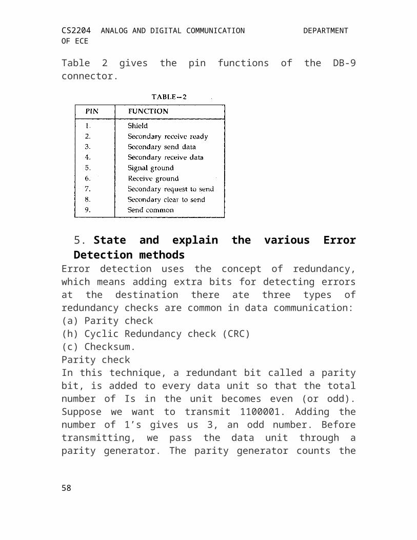
CS2204 ANALOG AND DIGITAL COMMUNICATION DEPARTMENT OF ECE
packet and is equal to T where T is the duration of a packet.
Hence the commutator returns to each individual buffer at times separated by the
The channel bandwidth required is equal to the bit rate on the channel, if QPSK is employed and which is equal to B = Kfb Hz.
Fig. 4 (a) TDMA system (b) Timing patterns. The higher level of each “Waveform” marks the dwell time of the commutator on each switch posi-tion.
If the K user has a continous need to transmit, TDMA systems at that stage are very efficient. TDMA will become inefficient when the users need varies 58
CS2204 ANALOG AND DIGITAL COMMUNICATION DEPARTMENT OF ECE
from time to time due to the type of communication employed. Since a user pays for the times-lot even when he fails to transmit it, since the time-slot is wasted, an additional user could have been admitted to the network during this wasted time.
***********************
59