Embed Size (px)
Citation preview
ISYS 200 Week #4 1
Systems Analysis IData Flow Diagrams
ISYS 200
Glenn Booker
ISYS 200 Week #4 2
Data Flow Diagrams
Data Flow Diagrams (DFDs) are the primary tool for summarizing the processes a system can perform
They are useful both for capturing the existing system’s capabilities, and then are revised to show the new system’s processes
A DFD shows processes, entities, and data stores, connected by data flow lines
ISYS 200 Week #4 3
Data Flow Diagrams
Processes are the functions some user can perform using the system
Users indicate the kind of user who is allowed to perform each process (clerk, sales manager, etc.)
The data stores on a logical DFD are a high level description of the types of data storage needed to perform each process
ISYS 200 Week #4 4
Data Flow Diagrams
DFDs can show either the logical structure of processes, or the physical structure Logical structure shows all possible processes,
regardless of where they occur in the system Physical structure indicates what physical parts
of the system (e.g. type of servers) perform each kind of process
Unless specified, assume we imply a logical DFD
ISYS 200 Week #4 5
DFD Notation
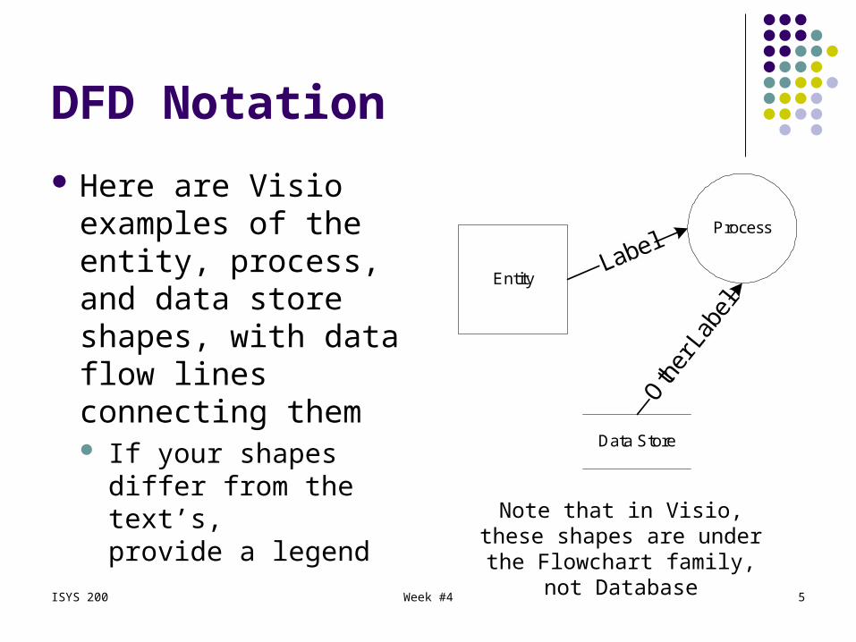
Here are Visio examples of the entity, process, and data store shapes, with data flow lines connecting them If your shapes differ
from the text’s, provide a legend
Entity
Data Store
Process
Note that in Visio, these shapes are under the Flowchart family,
not Database
ISYS 200 Week #4 6
DFD Scope
A DFD does not show any kind of business rules for processes – just all possible paths No decisions, or conditions (if)
A logical DFD does not show the subsystems involved in a process We might show a Customer data store, but
don’t specify how or where is it implemented Processes may be manual or automated –
there is no distinction on a logical DFD
ISYS 200 Week #4 7
DFD Notation – Entities
More formally, the ‘kind of user’ is called an entity in the text – an unfortunate choice when we get to the ERD* An entity can be a type of user, or some kind of
external system with which your system interacts External systems might include other information
systems within or outside of your organization Like a legacy system used for processing invoices
* An entity in a DFD could be more general than an entity in an ERD
ISYS 200 Week #4 8
DFD Notation – Processes
Processes are the business functions performed using the system
We prefer a “verb (adjective) noun” naming convention for processes Prepare shipping invoice Enter new customer Remove backorder Update reorder parameters
Number processes for later reference
ISYS 200 Week #4 9
DFD Notation – Data Stores
A data store is a kind of data needed to perform processes Temporary data isn’t shown on a logical DFD Data stores can be manual or automated
A data store is labeled with the type of data Sales Customer
Put a reference number in front of each data store name, e.g. D1, D2, D3, etc.
ISYS 200 Week #4 10
Creating a Logical DFD
Data flow diagrams can be done on multiple levels of detail, as your understanding of the system evolves Start by listing the processes and activities
associated with your system, and look for entities, processes, and data stores
Create a context diagram (the simplest DFD) Create the diagram 0 data flow diagram, showing
entities, general processes and data stores Include data flow names
ISYS 200 Week #4 11
Creating a Logical DFD
Pick significant processes, and expand them into more detailed DFDs if needed
The numbering of processes reflects the level of detail shown The system is process ‘0’ in a context diagram In a diagram 0 DFD, the processes are
numbered 1, 2, 3, etc. (parent diagram) To expand on process 3, Diagram 3 would show
processes 3.1, 3.2, 3.3, etc. (child diagram)
ISYS 200 Week #4 12
Creating a Logical DFD
Watch the zeros! Process ‘0’ does NOT appear on the Diagram 0 DFD! Diagram ‘x’ means it is a DFD which expands
on the contents of the process numbered ‘x’ So Diagram 3.2 would contain processes 3.2.1,
3.2.2, 3.2.3, etc. Page 200 has a good Diagram 0 DFD
This is the lowest level of DFD detail we’ll use
ISYS 200 Week #4 13
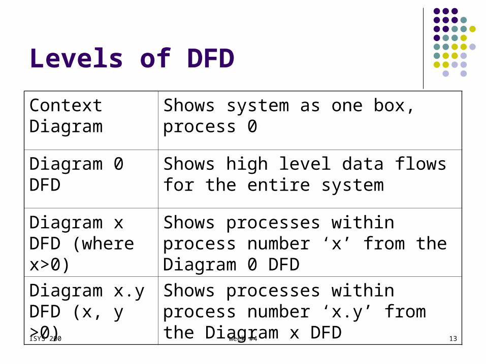
Levels of DFD
Context Diagram
Shows system as one box, process 0
Diagram 0 DFD Shows high level data flows for the entire system
Diagram x DFD (where x>0)
Shows processes within process number ‘x’ from the Diagram 0 DFD
Diagram x.y DFD (x, y >0)
Shows processes within process number ‘x.y’ from the Diagram x DFD
ISYS 200 Week #4 14
Rules for Data Flow Diagrams
Entities never connect directly to a data store They must use some process to access or modify
the data Hence a user or external system can only connect
to one or more processes All kinds of entities which appear on the
context diagram must appear somewhere on the DFD Otherwise they don’t do anything!
ISYS 200 Week #4 15
Rules for Data Flow Diagrams
Each process will connect to at least one user or external system, and one data store Each process may send data to one or more
data stores, and/or get data from one or more data stores
Processes rarely connect to other processes Each process needs data flowing in and out of it Fix processes which have logically incomplete
inputs and outputs
ISYS 200 Week #4 16
Rules for Data Flow Diagrams
Leave in processes which calculate something, make decisions, manipulate data, or organize data
Data flows into and out of parent and child diagrams should be consistent
Data flows pointing away from an entity imply they provide input to the system
Data flows pointing to an entity imply they receive an output from the system
ISYS 200 Week #4 17
Rules for Data Flow Diagrams
Every data store needs data flowing both in and out somewhere on the diagram Otherwise you have a data black hole = inputs
but no output, or A miracle = outputs without input
Data stores do not connect directly to each other A process is needed to take data from one
data store, and write it to another one
ISYS 200 Week #4 18
DFD Evolution
Typically three steps are used with DFDs The first DFD captures the processes used
by the existing system The second DFD describes the processes
to be used by the new system A third DFD is a physical description of the
new system The first two DFDs are logical DFDs
Now we’ll mention the physical DFD
ISYS 200 Week #4 19
Physical DFDs
A physical DFD shows how processes will be implemented Entities are still entities Data stores are now files, and may include
temporary files Processes are now specific programs or
manual procedures See example on page 202
ISYS 200 Week #4 20
Partitioning a DFD
A Physical DFD can be partitioned to help determine the structure of the application
Partitioning groups processes by similarity Group manual processes vs. automated ones Group processes by the type of user Group processes by their time sequence Group processes which perform similar tasks Group processes which use similar resources
ISYS 200 Week #4 21
Partitioning
Group processes to ensure consistent data Group processes for security protection
Partitioning can also be done at the user interface level (e.g. a web site) for the same kinds of reasons
ISYS 200 Week #4 22
CRUD Matrix
A CRUD matrix maps data and processes to verify that all data is used correctly throughout the system
CRUD refers to the possible activities Create new data Read existing data Update or change or modify existing data Delete existing data
ISYS 200 Week #4 23
CRUD Matrix
The CRUD matrix shows process names in each row, and data stores in each column (p. 203) For each process and data store, enter C, R, U,
and/or D to indicate the possible data activities A blank indicates that process does not affect
that data store For further clarity, use the process and
data store numbers from the DFD
ISYS 200 Week #4 24
CRUD Matrix
At a minimum, make sure each data store is Created and Read by at least one process Update and Delete may be optional
ISYS 200 Week #4 25
Event Response Table
Further documentation of processes is encouraged
One form is the event response table (p. 204) This provides a summary of each process
Event – is the process name Source – is the entity who starts the process Trigger – is the data or stimulus which is needed
from the source
ISYS 200 Week #4 26
Event Response Table
Activity – is a brief description of the process Response – is typically an interface screen
(for a human Destination) or type of data (for an external system Destination) which conveys the results of the process
Destination – is the entity which received the output from the process (whether human or an external system)
ISYS 200 Week #4 27
Other DFD Documentation
Another approach for documenting a DFD is to outline the contents of the DFD before making the drawing
Identify the entities and processes Make a table to show
Process Name, Description, Entities, Inputs, Outputs, and Data Sources
ISYS 200 Week #4 28
Other DFD Documentation
Except Description, these all correspond directly to stuff which appears on the DFD: Process Name – the label inside the process
shape (later add the numbering) Description – a brief description of the process Entities – are the entities which participate in
the process Inputs – are data flow(s) leading into the process Outputs – are data flow(s) leading out of
the process

ISYS 200 Week #4 29
Other DFD Documentation
Data Sources – are the data stores connected to the process (later add the numbering)
Notice that the Inputs and Outputs are the data flow labels, which could be coming from or to entities or data stores
Use the table to help arrange the processes For example, sort the processes by Entity to
help see which processes should be grouped together on the DFD
ISYS 200 Week #4 30
Other DFD Documentation
Duplication of entities and data stores is permitted on a DFD for clarity Flag or footnote them to indicate a deliberate
duplicate is being used In addition to the description of processes,
provide a brief description of the data stores and entities Note any assumptions about the scope or
responsibilities of anything in the DFD which affected your modeling decisions