Embed Size (px)
Citation preview
ISTANBUL TECHNICAL UNIVERSITY GRADUATE SCHOOL OF SCIENCE
ENGINEERING AND TECHNOLOGY
M.Sc. THESIS
JUNE 2012
POLYPYRROLE /POLY(ACRYLONITRILE-CO-METHYLACRYLATE)
NANOCOMPOSITES, NANOFIBERS AND THEIR CHARACTERIZATIONS
Thesis Advisor: Prof. Dr. A. Sezai SARAÇ
Yasemin YERLİKAYA
Department of Nano Science & Nano Engineering
Nano Science & Nano Engineering Program
Yapı Mühendisliği Programı
Anabilim Dalı : Herhangi Mühendislik, Bilim
Programı : Herhangi Program

Department of Nano Science & Nano Engineering
Nano Science & Nano Engineering Program
ISTANBUL TECHNICAL UNIVERSITY GRADUATE SCHOOL OF SCIENCE
ENGINEERING AND TECHNOLOGY
M.Sc. THESIS
JUNE 2012
POLYPYRROLE /POLY(ACRYLONITRILE-CO-METHYLACRYLATE)
NANOCOMPOSITES, NANOFIBERS AND THEIR CHARACTERIZATIONS
Thesis Advisor: Prof. Dr. A. Sezai SARAÇ
Yasemin YERLİKAYA
513101020


İSTANBUL TEKNİK ÜNİVERSİTESİ FEN BİLİMLERİ ENSTİTÜSÜ
Yüksek Lisans Tezi
HAZİRAN 2012
POLİPİROL /POLİ(AKRİLONİTRİL-KO-METİLAKRİLAT) NANO
KOMPOZİTLERİ, NANOFİBERLERİ VE KARAKTERİZASYONLARI
Tez Danışmanı: Prof. Dr. A. Sezai SARAÇ
Tez Danışmanı: Prof. Dr. A. Sezai SARAÇ
Yasemin YERLİKAYA
513101020
Nano Bilim ve Nano Mühendislik Anabilim Dalı
Nano Bilim ve Nano Mühendislik Programı


v
Yasemin Yerlikaya, a M.Sc Student of ITU Institute of Science and
Technology/Graduate School of Istanbul Technical University student ID
513101020, succesfully defended the thesis entitled “POLYPYRROLE
/POLY(ACRYLONITRILE-CO-METHYLACRYLATE)
NANOCOMPOSITES, NANOFIBERS AND THEIR
CHARACTERIZATIONS”, which she prepared after fulfiling the requirements
specified in the associated legislations, before the jury whose signatures are below.
Thesis Advisor : Prof. Dr. A.Sezai SARAÇ ..............................
İstanbul Technical University
Jury Members : Yrd. Doç. Dr. Fatma Neşe KÖK .............................
Istanbul Technical University
Prof. Dr. Tülay TULUN .............................
Cyprus International University
Date of Submission : 05 May 2012
Date of Defense : 08 June 2012

vi

vii
To my family,

viii

ix
FOREWORD
First of all, I would like to express my gratitude to my thesis supervisor, Prof. Dr.
A.Sezai SARAÇ for his encouragement, guidance, helpful critics and discussions in
my studies.
I would like to thank Res.Ass.Timuçin BALKAN, Res.Ass.Hacer DOLAŞ and Cem
ÜNSAL for sharing their chemical knowledge with me, my laboratory friends Merih
Zeynep AVCI, Burcu ARMAN, Keziban HÜNER, Ece POLAT, Başak
DEMİRCİOĞLU, Selda ŞEN for their kind and helpful encouragement and pation.
I also send my thanks to Organik Kimya A.Ş. for helping me determine the particle
sizes of my nanoparticles by Particle Size Analyser.
I finally would like to thank to my family, my mother Sevdiye YERLİKAYA, my
father Orhan YERLİKAYA, my brother Mustafa YERLİKAYA since they always
supported me with their heart. I was able to accomplish everything in my life thanks
to their love.
June 2011
Yasemin YERLİKAYA
Engineer

x
xi
TABLE OF CONTENTS
Page
FOREWORD ............................................................................................................ ix
TABLE OF CONTENTS ......................................................................................... xi
ABBREVIATIONS ................................................................................................ xiii
LIST OF TABLES................................................................................................. xvii
SUMMARY ............................................................................................................. xix
ÖZET ........................................................................................................................ xxi
1. INTRODUCTION .................................................................................................. 1
2. THEORETICAL PART ........................................................................................ 3
2.1 Polyacrylates ...................................................................................................... 3
2.2 Polyacrylonitrile ................................................................................................. 5
2.3 Methy Acrylate................................................................................................... 6
2.4 Conductive Polymers ......................................................................................... 7
2.5 Pyrrole and Polypyrrole ..................................................................................... 8
2.6 Electrospinning ................................................................................................ 10
2.7 Emulsion Polymerization ................................................................................. 12
3. EXPERIMENTAL ............................................................................................... 15
3.1 Materials ........................................................................................................... 15
3.2 Synthesis of P(AN-co-MA) nanoparticles ....................................................... 15
3.3 Synthesis of Ppy / Poly(AN-co-MA) Nanoparticles ........................................ 16
3.4 Preparation of Electrospinning and Film Solutions of Nano Composites ....... 17
3.4.1 Electrospinning of nanocomposites .......................................................... 17
3.4.2. Preparing films of nanocomposites .......................................................... 18
4. RESULTS AND DISCUSSION .......................................................................... 21
4.1. Nanoparticle Characterization ......................................................................... 21
4.1.1 SEM analysis of P(AN-co-MA) and PPy/p(AN-co-MA) nanoparticles
obtained from emulsion latexes ......................................................................... 21
4.1.2 Particle size analysis of P(AN-co-MA) and PPy/p(AN-co-MA)
nanoparticles obtained from emulsion latexes ................................................... 23
4.1.3 FTIR-ATR characterization of P(AN-co-MA) and PPy/p(AN-co-MA)
nanoparticles obtained after precipitating and drying the emulsions ................. 25

xii
4.1.4 UV-Visible Spectroscopy characterization of P(AN-co-MA) and
PPy/p(AN-co-MA) nanoparticles obtained after precipitating and drying the
emulsions ............................................................................................................ 30
4.1.5. The relationship between UV-Visible spectroscopy reflectance and
particle size of nanoparticles .............................................................................. 31
4.1.6. Differential scanning calorimetry analysis of p(AN-co-MA) and PPy /
p(AN-co-MA) nanoparticles .............................................................................. 34
4.2. Nanofiber and Film Characterizations ............................................................ 35
4.2.1. Nanofiber characterization ....................................................................... 35
4.2.2. Film characterization ................................................................................ 39
5. CONCLUSIONS................................................................................................... 41
CURRICULUM VITAE .......................................................................................... 53

xiii
ABBREVIATIONS
µl : Microliter
AN : Acrylonitrile
cm : Centimeter
DBSA : Dodecyl benzen sulfonic acid
DMA : Dynamic Mechaniz Analyzer
DMF : Dimethyl formamide
DSC : Differential Scanning Calorimetry
FTIR-ATR : Fourier Transform Infrared-Attenuated Total Reflectance
g : Gram
KPS : Potassium Persulfate
MA : Methyl acrylate
ml : Mililiter
P(AN-co-MA) : Acrylonitrile – Methyl acrylate copolymer
PAN : Polyacrylonitrile
PPy/p(AN-co-MA) : Polypyrrole / Poly Acrylonitrile-co-Methylacrylate composite
PPy : Polypyrrole
Py : Pyrrole
SEM : Scanning Electron Microscopy
Tg : Glass Transition Temperature

xiv

xv
LIST OF FIGURES
Figure 2.1: Acrylonitrile……………………………………………………………..3
Figure 2.2: Skeletal Formula of Methy Acrylate……………………………………7
Figure 2.3: Formula of Pyrrole……………………………………………….……...9
Figure 2.4: Formula of Polypyrrole………………………………………….…......10
Figure 2.5: Schematic of Electro Spinning Setup…………………………………..11
Figure 2.6: Schematic View of Emulsion Polymerization……………………........13
Figure 3.1: Monomers used in synthesis of Poly(AN-co-MA)………………...…..16
Figure 3.2: Poly(AN-co-MA) structure…………………………………………….16
Figure 3.3: Estimated mechanism of composite formation………………...……....17
Figure 3.4: A representative picture taken during electrospinning……..……...…...18
Figure 3.5: Films obtained without pyrrole addition and with different amounts of
pyrrole addition………………………………………...………………19
Figure 4.1: The SEM images of both with addition of pyrrole and wihout addition of
pyrrole………………………………………………………………….22
Figure 4.2: The colour change of latex nanoparticles that sampled from emulsion
media by increasing pyrrole addition…………………………………..24
Figure 4.3: FTIR-ATR reflectance spectrophotometer in Electropol & Nanotech
Laboratory……………………………………………………………...26
Figure 4.4: FTIR-ATR spectra of p(AN-co-MA) nanoparticles……...…….………26
Figure 4.5: The absorbance ratio of C≡N (2242) / C=O streching (1726)………... 27
Figure 4.6: FTIR-ATR spectra of Ppy / p(AN-co-MA) nanoparticles by increasing
amounts of polypyrrole……………….………………………………...28
Figure 4.7: The appearing peak at 1554 due to the increasement of pyrrole
addition………………………………………………….........................28
Figure 4.8: The 1553 and 1449 (Ppy ring vibtarion) ratio to 2243 (C≡N formation of
AN)…………………………………………………………………..….29
Figure 4.9: The comparation of pure Ppy obtained at the same emulsion conditions
without matrix, Ppy / p(AN-co-MA) and P(AN-co-MA)……………...29
Figure 4.10: The UV-Visible Spectrometer in the Electropol&Nanotech
Laboratory……………………………………………………………...30
Figure 4.11: The UV-Visible spectrum of pure DMF, p(AN-co-MA) and increasing
amounts of polypyrrole containing Ppy/p(AN-co-MA) nanoparticles in
DMF solution…………………………..………………………………31
Figure 4.12: The probable reflection on the spectrum…………...…………………32
Figure 4.13: The certain point to examine the reflection…………...………………33
Figure 4.14: The proportional increasement of the particle size in relation with the
UV absorbance at 325 nm……………………………………………...34
Figure 4.15: The Tg values of nanocomposites as increasing order………...……...35
Figure 4.16: The SEM images of left to right: 0, 30, 50, 60, 100 µl pyrrole added
samples………………………………………………………………...36
Figure 4.17: (a) is the nanofiber that not contains polypyrrole and non-porous, (e) is
the nanofiber that contains polypyrrole and porous……………………37

xvi
Figure 4.18: The 4 times bended nanofiber sheets. Upper: Ppy / p(AN-co-MA)
Lower: p(AN-co-MA)…………………………………………………38
Figure 4.19: The stress-strain curves and Young’s Modulus of nanofibers…...…...38
Figure 4.20: Films that obtained from a)30 µl b)50 µl c)60 µl d)100 µl pyrrole
added nanoparticles…………………………………………………...39
Figure 4.21 Stress-strain curves and Young’s Modulus of the films, from highest to
lowest: obtained from 100 µl, 60 µl, 50 µl, 30 µl pyrrole added
nanoparticles………………………………………………………......40

xvii
LIST OF TABLES
Table 3.1 : The total monomer, AN, MA, DBSA and KPS composition in feed......15
Table 3.2 : P(AN-co-MA) and Ppy/ p(AN-co-MA) nanocomposit solutions used for
electrospinning ………………………………………………………...17
Table 4.1 : P(AN-co-MA) and Ppy/ p(AN-co-MA) latex nanoparticle sizes
measured on SEM images……………………………………………....23
Table 4.2 : P(AN-co-MA) and Ppy/ p(AN-co-MA) latex nanoparticle sizes
measured by Particle Size Analyzer………………………………….....25
Table 4.3 : The comparison of the absorption at the 325 nm, pyrrole amount and
particle size……………………………………………………………..33
Table 4.4 : The increasing Tg values acording to increasing pyrrole addition……..35
Table 4.5: Average diameter and standart deviation of diameters according to added
pyrrole amount………………………………………………………….36

xviii

xix
POLYPYRROLE / POLY(ACRYLONITRILE-CO-METHYLACRYLATE)
NANOCOMPOSITES, NANOFIBERS AND THEIR CHARACTERIZATIONS
SUMMARY
This study can be mainly categorized into two parts, first of all obtaining
Polypyrrole/Acrylonitryle-co-Methylacrylate latexes that obtained by emulsion
polymerization, secondly obtaining nanofibers by electrospinning method from the
precipitated form of these nano-composites. Emulsion polymerization of
Acrylonitrile (AN) and Methylacrylate (MA) was performed in the aqueus medium
with the precence of surfactant Dodecyl Benzen Sulfonic Acid (DBSA) and initiator
Potassium Persulfate (KPS). After copolymerization, different amounts of pyrrole
droplets are added into emulsion latexes and reaction continued with the left initiator.
At the end of the polymerization of polypyrrole with the AN-co-MA latexes,
nanoparticles of Ppy/(AN-co-MA) are sampled and the morphology is characterized
by Scanning Electron Microscopy(SEM). Also the nanoparticle size is determined by
Particle Size Analyzer (light scattering) and measuring on SEM images.
Nanoparticles were successfully obtained as 83-103 nm diameter changing by the
different polypyrrole amounts. Then the polypyrrole containing and non-containing
nanoparticle latexes are precipitated with methanol and dried in oven. Samples
without polypyrrole shown a hard-plasticity, however polypyrrole containing
samples are appeared as powder-like structure. Then dried composites were
dissolved in Dimethyl Formamide (DMF) in a certain percent of solvent by weight
and electrospinned by an electrospinning device that contains a power supplier,
pump, syringe and metal collector. The distance between collector and syringe,
solution percentage by weight, applied voltage was not changed by trials. At the end
of the electrospinning, nanofibers were obtained in the range of 200-700 nm
diameter. In addition to nanofibers, the DMF containing solution of nanocomposites
were poured into special surfaces and films are obtained. Nanofibers are
characterized by SEM and Dynamic Mechanic Analyzer. Dried particles are
chacterized by both Fourier Transform Infrared-Attenuated Total Reflectance (FTIR-
ATR), UV-Visible Spectroscopy and Differantial Scanning Calorimetry (DSC). Uv-

xx
Visible Spectroscopy results are examined with particle sizes and it was observed
that the UV-Visible absorption is directly proportional with the particle size of
nanoparticles. DSC analysis showed that the glass transition temperature is increased
by the increasing pyrrole addition . The films were chacterized by Dynamic-
Mechanic Analyzer (DMA) as obtaining stress-strain curves, and it was obviously
seen that the Young’s Modulus of films are increased by increasing amounts of
pyrrole added.

xxi
POLİPİROL /POLİ(AKRİLONİTRİL-KO-METİLAKRİLAT) NANO
KOMPOZİTLERİ, NANOFİBERLERİ VE KARAKTERİZASYONLARI
ÖZET
İletken polimerler son zamanlarda oldukça fazla ilgi çekmeye başlamış ve iletkenlik
gereken alanlarda polimerlere yönelinmesi, bu polimerlerin yeni kullanım alanlarına
entegre edilmesi çalışmalarını hızlandırmıştır. İletken polimerlerin proses edilme
sırasında gösterdikleri birtakım olumsuz özellikler, bu malzemelerin çeşitli
polimerlerle bir araya getirilerek avantaja çevrilmesi konusunu gündeme getirmiştir.
Kabuk-Öz (Core-Shell) yapının oluşturulması da bu çalışmalardan biridir. Bu
çalışma temel olarak iki kategoriye ayrılabilir. İlk olarak emülsiyon polimerizasyonu
yöntemiyle Polipirol/Poli(Akrilonitril-Ko-Metil akrilat) lateksinin elde edilmesi,
ikinci olarak ise elde edilen lateks nano kompozit yapıdan, yapı çöktürülüp
kurutulduktan sonra elektrospinning yöntemi ile nanofiber elde edilmesi
gerçekleştirilmiştir. Öncelikle akrilonitril (AN) ve metil akrilatın (MA) sulu ortamda
emülsiyon polimerizasyonu, ortamda yüzeyaktif madde olan dodesil benzen sülfonik
asit (DBSA) ve başlatıcı potesyum per sülfat (KPS) bulunmasıyla tamamlanmıştır.
Kopolimerizasyon gerçekleştikten sonra işlem sonlandırılmadan, polimerizasyon
devam eder durumda iken emülsiyon ortamına farklı miktarlarda pirol (Py) damlaları
eklenerek ortamda ilk polimerizasyondan kalmış olan başlatıcıyla polimerizasyona
devam edilmiştir. Burada önemli olan, pirol ekleme aşamasında pirolün
kopolimerleşmesi için ilave başlatıcı kullanılmamış olmasıdır, ortamda var olan
başlatıcı ile işleme devam edilmiştir. Pirolün akrilonitril-ko-metilakrilat lateksi ile
kopolimerleşmesi sonrasında Ppy/P(AN-co-MA)’nın lateks ortamındaki
nanopartiküllerinden (henüz çökeltme ve kurutma yapılmadan) örnek alınıp,
morfolojisi Taramalı Elektron Mikroskobu (SEM) ile incelenmiştir. Aynı zamanda
Partikül Boyut Analiz (Işık Saçılımlı) cihazı ile ve SEM görüntüleri üzerinden ölçüm
alma yöntemiyle nanopartikül boyutları belirlenmiştir. Değişen polipirol
miktarlarıyla başarılı bir şekilde 83-103 nm çaplarında küre şekilli nanopartiküller
elde edildiği görülmüştür. Ardından polipirol içeren ve içermeyen lateksler
(çöktürülmemiş nanopartikül içeren emülsiyon ortamı) metanol ile çöktürülerek
fırında yapısında kalan su tamamen buharlaşıncaya kadar kurutulmuştur. Polipirol

xxii
içermeyen numuneler (P(AN-co-MA) tek parça halinde katılaşıp, kırılmaz-sert-
plastisite yapısı göstermiş olup, içerenler ise (Ppy/P(AN-co-MA)) biraraya
yapışmayıp ince toz formunda, yumuşak yapıda ortaya çıkmışlardır. Yapıya polipirol
katıldığında oluşan nihai ürünün toz yapıda olması, proses edilebilmeyi kolaylaştırıcı
yönde gözükmektedir; aksi takdirde materyal polipirol içermediğinde kırılmaz,
bükülmez, ufalanmaz bir yapıda kullanım güçlüğü çıkarmaktadır. Sonra bu
kompozitler kütlece yüzde gözönünde bulundurularak belli miktarlarda DMF
(Dimetil formamid) içinde çözülmüş ve güç kaynağı, pompa, şırınga ve metal
kollektörden oluşan bir elektrospin cihazında nanofiber haline getirilmiştir. Bu
işlemde enjektör-kollektör arası mesafe sabit tutulmuştur. Farklı voltaj miktarlarında
ön denemeler yapılmış ve her konsantrasyondaki çözeltinin nanofiberlerinin en
düzenli ve damlacıksız elde edilebildiği voltaj 15 kV olarak belirlenmiştir. Deneyler
15 kV’lik voltaj ile yapılmıştır. Bu denemeler esnasında kollektör ile şırınga
arasındaki mesafe, çözücü solüsyonunun kütlece yüzdesi ve uygulanan voltaj
değiştirilmemiştir. Elektrospinning sonucunda SEM ile inceleme yapıldığında 200-
700 nm çaplarında nanolifler elde edildiği görülmüştür. Nanofiberlere ek olarak hem
polipirol içeren hem de içermeyen çöktürülmüş ve kurutulmuş nano kompozitlerin
DMF çözücüsü içeren çözeltisi özel cam yüzeylere dökülmüş, fırında çözücü
buharlaşana kadar kurutulmuş ve filmler elde edilmiştir. Film çözeltileri kütlece sabit
oranda hazırlanmıştır ve daha fazla pirol eklenmiş olan nano kompozit malzemeden
elde edilmiş olan filmlerin rengi, oluşan polipirol yoğunluğuna bağlı olarak daha
koyu renk olmuştur. Nanofiberler SEM’in yanısıra DMA (Dinamik Mekanik
Analizör) ile de karakterize edilmiştir. Nanofiberler DMA ile incelenmeye
çalışıldığında, kollektörden toplanan nanofiberlerin çok ince ve dayanıksız olması
sebebiyle bu lifler birkaç kat kalınlaştırma yoluna gidilmiştir. Bu nedenle
nanofiberler kollektörün üzerinden toplandıktan sonra su ile ıslatılmış ve belirli
boyutlarda iki sefer katlanıp toplamda dört kat yüzey oluşturulmuş ve şekil alması
için kurutulmuştur. Malzeme suda çözünebilir olmadığı için bu işlem nanofiberlere
herhangi bir zarar vermemiştir. Ancak yapılan işlemler sonucunda nanofiberler
üzerinden DMA ile net bir ölçüm alınamamış olup, bunun fiberlerin karışık
doğrultularda yönlenmesi ve bu sebeple lif demetinin bazı kısımlarında kırılma
noktaları oluşması sebebiyle ortaya çıktığı düşünülmektedir. Kurutulmuş partiküller
ise hem Fourier Dönüşüm Kızılötesi – Azaltılmış Toplam Yansıma Spektroskopisi
(FTIR-ATR), hem UV-Görünür Spektroskopisi, hem de Diferansiyel Tarama

xxiii
Kalorimetresi (DSC) ile karakterize edilmiştir. UV-Görünür Spektroskopisi sonuçları
partikül boyutu ile ilişkilendirilerek incelenmiştir ve UV emiliminin doğrudan
nanopartiküllerin boyutuyla orantılı olduğu görülmüştür. Partikül boyutu büyüdükçe
ışının kırılması çoğalmış ve UV eğrilerinin başlangıç noktaları yer değiştirmiştir.
UV-Görünür spektroskobisinde, kompozitlerin içinde polipirol oluşumunun varlığı
açıkça görülmüştür. FTIR-ATR ölçümlerinde de nano kompozitte polipirol oluşumu
görülmüştür, son materyalin içinde polipirole ait pikler ortaya çıkmıştır; bu da yapıda
polipirol meydana geldiğini göstermektedir. FTIR-ATR spektrumunda p(AN-co-
MA) ve PPy’ye ait pikler ayrı ayrı göründüğü ve arada ilave bir bağ görünmediği
için PPy ile p(AN-co-MA)’nın arasında kimyasal bağdan ziyade fiziksel bağ
oluştuğunu düşündürmektedir. Bu da içeride p(AN-co-MA), dışarıda ise PPy
oluşumu şeklinde core-shell yapının oluşmuş olabileceğini destekleyen bir sonuçtur.
DSC Analizleri ortama eklenen pirol miktarı arttıkça camsı geçiş sıcaklığının
arttığını göstermiştir. Bunun sebebi olarak ise yapıda oluşan polipirol ile genel
yapının direncinin arttığı, buna bağlı olarak camsı geçiş sıcaklığının yükseldiği
düşünülmüştür. Filmler de nanofiberler gibi DMA ile analiz edilmiş, stres-uzama
eğrileri oluşturularak karakterize edilmiştir. Daha fazla Py eklenmiş kompozitten
elde edilen filmler daha koyu renk, kırılgan ve parlak olurken, az Py eklenen veya
hiç Py eklenmeyen nano kompozitten oluşan filmler açık renk (hatta şeffaf), daha
elastik ve daha az parlak oluşmuştur. Ölçümlerin sonucunda eklenen Py ve oluşan
PPy miktarı arttıkça filmlerin Young Modüllerinin arttığı açıkça görülmüştür. PPy
genel olarak kristalin yapıda olduğu için polimer zincirinde esneklik
göstermemektedir, dolayısıyla yapıdaki PPy miktarı arttıkça uzama olmadan
dayanılan kuvvet miktarı artmış; dolayısıyla Young Modülü yüksek çıkmıştır. Tüm
bu sonuçlar değerlendirildiğinde yeni bir nano-kompozit malzeme oluştuğu; Ppy’nin
özellikleri ile p(AN-co-MA)’nın özelliklerininin bir arada görüldüğü; PPy’nin proses
edilebilirliğinin artırılarak nanofiber elde edilebildiği anlaşılmıştır. Bu malzeme
ileride hem nanopartikül olarak kullanım alanı bulabilecek, hem de nanolif şeklinde
kullanılabilecek potansiyele sahiptir.

xxiv

1
1. INTRODUCTION
Conductive polymers and their composites are being interested frequently in recent
years and polypyrrole is most commonly used types of conjugated conductive
polymers.
Since their good conductivity properties [1] and potential applications in various
fields like sensors [2–4], actuators [5, 6], catalysis[7], field effect transistors[8], light
emitting diodes[9], capacitors[ 10] etc., conducting polymers like polypyrrole
polyaniline, polythiophene, polyacetylene, poly (p-phenylene sulfide) and poly (p-
phenylene vinylene) etc. have been commonly studied and used in recent years.
Although this advantages that thay have, they have also some disadvantages such as
being often brittle in nature and hence having difficulcy to make film from them. In
order to overcome these difficulcies, much attention has been made in combining
these conducting polymers with mechanically stable insulating polymers to give
core–shell morphology. These composite particles have a wide area of applications
such as antistatic coating, dampers, clutches, electrodes, separation membranes,
electro chromic devices, electrochemomechanical actuators, and sensors [11, 12].
These kinds of core–shell conducting composites have two advantages which the
first one depends on the type of insulating polymer used as core. These conducting
polymer-coated latex particles can show very good mechanical stability. Second
advantage is the amount of conducting polymer used can be greatly reduced in the
shell phase, therefore the composit material maintains its conductivity without much
loss [13].
Latex particles coated by conducting polymer were first reported in 1987 [14] and
this study have found widespread attention [15–18]. Jianjun Wang et al. developed a
core of a thermoplastic non-conducting polymer covered by a corona of a
polyelectrolyte (e.g., polystyrene sulfonate, (PSS)) and into this corona (i.e., matrix)
domains of a conducting polymer, polypyrrole (PPy) was embedded by oxidative
polymerization of the suitable monomer (pyrrole) such that an electrical percolating
Shell is formed [19]. Han Chen et al. studied the voltammetric conversion of
conducting polyaniline-coated polystyrene latex particles which dispersed in aqueous

2
acid solution to find both a relationship between the partial reaction and particle size,
but also the irreversibility of the conversion [20]. Huang Liyan et al. developed a
series of mono dispersed styrene-butyl acrylate (SBA) copolymer latex particles with
different butyl acrylate contents, coated with polypyrrole and studied both the effects
of the concentration of polypyrrole, the butyl acrylate content in SBA copolymer and
the nature of the counter-anion on the electrical conductivity of compression-
moulded samples [13]. Liang Guo et al. studied and developed coated Fe3O4 with
polystyrene particles and they used dispersion polymerization. Also they studied the
effect of a cross-linking agent and the mechanism of the polymer coating [21].
Another group, Ying Wang et al. synthesized electrically conductive core–shell
nanoparticles (PANI/PS-PSS) via coating poly (styrene-co-styrene sulfonate) (PS-
PSS) nanoparticles with polyaniline (PANI) . They studied about the stability of the
coated latexes and the conductivity of PANI/PS-PSS pellets. The role of the aniline
amount was also mentioned in this literature [22].
In this study, Acrylonitrile is chosen, since it is one of the most popular monomers of
chemistry and textile industry due to its common usage as a precursor of carbon
fibers by copolymerizing with some other monomers. Methyl acrylate monomer is
chosen for its hydrophobicity and suitability for being copolymer with acrylonitrile.
Hydrophobicity is an important factor to have core-shell nanostructures in emulsion
media with surfactant.

3
2. THEORETICAL PART
2.1 Polyacrylates
The kinds of polyacrylates are highly heat and oil resistant polymers. Several usage
areas exist for acrylate and methacrylate esters that they are used to obtain polymers
for textiles, latex paints, surgical cements and dental resins. The esters of acrylic and
methacrylic acid are shown the formula which can be seen in figüre 2.1.
Figure 2.1 : General Formula of Acrylates
R:H bonding is considered for acrylates and R:CH3 for methacrylates. The
substituents R’ can very in a wide area: from n-alkyl chains to more complicated
functional groups [23].
Esters of general acrylates are crystalline solids at ambient temperatures, then form
liquid at slightly higher temperatures. They are ready to polymerize and
copolymerize easily, being frequently employed in copolymers to obtain
alkalisoluble polymers. The acids of acrylates are water soluble, methacrylic acid, as
might be expected because of its angular methyl group, is more soluble in ester
monomers, and to some extent in styrene, and as such is more useful in
copolymerisation, especially if water based [24].
The first report of a polymeric acrylic ester was published in 1877 by Fittig and Paul
[25] and in 1880 by Fittig and Engelhorn [26] and by Kahlbaum [27], who observed
the polymerization reaction of both methyl acrylates and methacrylates. But it is a
chance to O. Röhm [28] in 1901 to recognize the technical potential of the acrylic
polymers. After continuing his work he got a U.S. patent on the sulfur vulcanization
of acrylates in 1914 [29]. Then in 1924, Barker and Skinner [30] researched and
published details of the polymerization of methyl and ethyl methacrylates. In 1927

4
[31], based on the extensive work of Röhm, the first industrial production of
polymeric acrylic esters was started by the Röhm & Haas Company in Darmstadt,
Germany (since 1971, Röhm GmbH, Darmstadt). After 1934, the Röhm & Haas Co.
in Darmstadt was able to produce an organic glass (Plexiglas) by a cast
polymerization process of methyl methacrylate [32]. Soon after, Imperial Chemical
Industries (ICI, England), Röhm & Hass Co. (United States), and Du Pont de
Nemours followed in the production of such acrylic glasses [33].
Acrylic polymers has a first-time usage as an interlining for automobile windshields,
but poly(methyl methacrylate) sheet (commercial name Plexiglas, Lucite) soon
became the main usage area of acrylic plastics. Poly(methyl methacrylate), chemical
Formula with [-CH2-CH(CH3)COOCH3-], has a light transmittancy of about 92%
and has good weathering resistance. It is widely used in aircraft wind shields,
bathtubs [34], electron beam or ion beam resistance of them is important in the
manufacture of microelectronics such as chips [35,36]. Poly(methyl methacrylate) is
used as an automobile lacquer and polyacrylonitrile, (-CH2-CHCN-)n, is used as a
fiber. Poly(ethyl acrylate),(-CH2–CHCOOC2H5-)n, is more flexible and has a lower
softening temperature than PMMA. Poly(hydroxyethyl methacrylate), is used for
contact lenses, and poly(butyl methacrylate) is used as an additive in lubricating
oils[34].
Whilst esters of acrylic acid give soft and flexible polymers, except for those with
long alkyl chains, methyl methacrylate polymerises to an extremely hard polymers.
The polymers in this series become softer with increasing alkyl chain lengths up to
C12. The highest alkyl chain acrylics in both series tend to give side chain
crystallisation.
The methacrylic ester series closely parallels the acrylics, but boiling points tend to
be somewhat higher, especially with the short chain esters. Methyl methacrylate is by
far the most freely available and least costly of the monomers of the series. As an
alternative to the simple alkyl esters, several alkoxyethyl acrylates are available
commercially, e.g. ethoxyethyl methacrylate CH3:C(CH3)COOC2H4OC2H5 and the
corresponding acrylate. The ether oxygen which interrupts the chain tends to
promote rather more flexibility than a simple carbon atom.
Some technical perfluorinated alkyl acrylates are as following they include N-
ethylperfluorooctanesulfonamido)ethyl acrylate CnF2n+1SO2N(C2H5)–CH2O–C(O)–

5
CH=CH2 (n approximately 7.5, fluorine content 51.7 %), the corresponding
methacrylate and the corresponding butyl derivatives. The ethyl derivatives are waxy
solids, the ethyl acrylate and the corresponding methacrylate derivative having a
melting range of 27–42 °C. The butyl acrylic derivative is a liquid, freezing at -10
°C. Butyl acrylate/Methyl methacrylates (BA/MMA), emulsıon copolymers are
versatile materials extensively used as adhesives (BA homopolymers and BA rich
copolymers) and coatings (BA/MMA 50/50 wt/wt copolymers). In spite of their
commercial importance, only a few literature reports dealing with the microstructural
properties of BA/MMA emulsıon copolymers have been published [37].
Polyacrylate elastomers can be prepared by the water emulsion system, suspension
system, solvent solution method, or even the mass (bulk homogenous)
polymerization process. Most are made by the water emulsion (latex) or the
suspension method. Peroxides or persulfate initiated free radical systems are most
commonly used in the presence of heat. Polymerization is usually taken to
completion. Coagulation is best with salts, followed by water washing and drying
with hot air, vacuum, or extrusion [38].
2.2 Polyacrylonitrile
Polyacrylonitrile (PAN) and copolymers of PAN have been widely studied for
almost a century for commercial/ technological exploitations. PAN may be
crosslinked, but also may exist without crosslinking. Crosslinking of PAN will
impart some of its important physical properties, such as insolubility and resistance
to swelling in common organic solvents. Recently, considerable efforts have been
devoted to its processing and fiber forming technologies. Among the various
precursors for producing carbon nanofibers (CNFs), PAN is the most commonly
used polymer, mainly due to its high carbon yield (up to 56%), flexibility for
tailoring the structure of the final CNF products and the ease of obtaining stabilized
products due to the formation of a ladder structure via nitrile polymerization [39–43].
Even though acrylonitrile (AN) was known as far back as 1893, but PAN, because of
difficulties in dissolving it for spinning, no progress was made in converting into a
usable fiber until 1925. Acrylonitrile monomer was also useful as a copolymer with
styrene, especially in a terpolymer with styrene and butadiene, known as ABS
rubber. The homopolymer of PAN was developed for manufacturing of fibers in

6
1940, after a suitable solvent was discovered by DuPont. PAN is soluble in polar
solvents like DMF, DMSO, DMAc, dimethylsulfone, tetramethylsulfide and aqueous
solutions of ethylene carbonate, as well as some mineral salts. PAN forms saturated
solution with 25% dissolved in DMF at 50 ◦C, which is high solubility compared to
other solvents [44]. PAN and its copolymers are predominantly white powders up to
250 ◦C, at which point they become darker due to degradation. Having a relatively
high Tg, these polymers have low thermal plasticity and cannot be used as a plastic
material. The high crystalline melting point (317 ◦C) of PAN, its limited solubility in
certain solvents coupled with superior mechanical properties of its fibers is due to
intermolecular forces between the polymer chains. Appreciable electrostatic forces
occur between the dipoles of adjacent C N groups and this intramolecular interaction
restricts the bond rotation, leading to a stiffer chain [45].
PAN-based CNFs are seemingly a new class of materials used in a wide array of
applications including filtration barriers, material reinforcements, garments,
insulators, medical and energy storage devices, and many more. However, their
unique properties make them perfect modern materials of choice across many
disciplines covering engineering, medicine, and biology. The accelerating
technologies of producing PAN-based nanofibers have now matured enough to
overcome the drawbacks of low production rate of few grams per hour in laboratory
environments to large industrial scale production. Nanofiber membranes comprising
sheets of randomly oriented nanofibers show an extremely effective removal method
with a high rejection rate of airborne particles by both physical trapping and
adsorption. It is anticipated that the future will witness many more applications of
PAN-based nanofibers in a wide variety of scientific disciplines. [46]
2.3 Methy Acrylate
The methyl acrylates are clear, colorless, volatile liquid with a slight solubility in
water and complete solubility in alcohols, ethers and many organic solvents.
Methacrylate esters are used to make polymers for textiles, latex paints, surgical
cements and dental resins. It can be used as a co-polymer in the process of
polymerization of polyanionic cellulose (PAC) polymers, to reduce the glass
transition temperature of the PAC polymers. It’s formula is CH2=CHCOOCH3. It
have boil point 79.6 °C at 760 mmHg and have melting point about -75 °C. Although
7
the monomer can be polymerized under the influence of heat, light, ionic or high
energy mechanisms, free radical initiation is the most commonly used method of
polymerization. The skeletal formula of Methyl Acrylate is shown in Figure 2.2.
Figure 2.2 Skeletal Formula of Methy Acrylate
Methyl acrylate is a volatile chemical compound classified as a methyl ester. It has a
characteristic odor used in the preparation of polyamidoamine (PAMAM)
dendrimers typically. The product is highly demanded for making different
industrial products. Moreover, this chemical compound is a flammable, water
insoluble, colorless liquid and possess the property to mix with most organic
solvents. Methyl acrylate is used in the production of coatings, elastomers, adhesives,
thickeners, amphoteric surfactants, fibers, plastics, textiles and inks.. Methyl acrylate
is also used in chemical synthesis. When used in latex paint formulations acrylic
polymers have good water resistance, low temperature flexibility and excellent
weathering and sunlight resistance.
2.4 Conductive Polymers
The discovery of conductive polymers is unique in its accomplishment as a possible
substitute for metallic conductors and semiconductors. The efforts forhaving a tailor-
made polymer in respect of its electrical, mechanical, optical and thermal properties
have been pursued by several research groups.
Generally, potentiostatic conditions are recommended to obtain thin films, while
galvanostatic conditions are recommended to obtain thick films. The electrochemical
technique has received wider attention both because of the simplicity and the added
advantage of obtaining a conductive polymer being simultaneously doped. Besides
this, a wider choice of cations and anions for use as ``dopant ions'' is available in the
electrochemical polymerisation process. Free-standing as well as self-supporting
conductive polymer films of desired thickness or geometry can be obtained. Using
this novel technique, a variety of conductive polymers like polypyrrole,

8
polythiophene, polyaniline, polyphenylene oxide pyrrole and polyaniline/polymeric
acid composite have been generated. Pyrrole in aqueous acetontrile solvent
containing tetraethyl ammonium tetra-uoroborate was electropolymerised in a two-
electrode electrochemical cell. Polypyrrole containing the BF4 ion (dopant) was
obtained as a film deposited on the platinum electrode surface [47].
Polymers were thought of as electrical insulators until the discovery that iodine-
doped polyacetylene exhibited electrical conductivity many orders of magnitude
higher than neutral polyacetylene. This discovery was published by [48] As a result
of this pioneering work, they received the 2000 NobelPrize in Chemistry. The
development of this new class of polymeric materials continues to offer the promise
of a wide range of novel applications including molecular electronics [49], actuators
[50], electrochromic windows/displays [51], supercapcitors [52], transistors [53],
photovoltaics [54] and corrosion protection [55]. This discovery opened up new
areas of research with many commercialproducts now incorporating polymers as
electrical conductors. For a more detailed review on the synthesis, properties and
applications of conductive polymers (CPs) consult [56] CPs consist of conjugated
chains containing pelectrons delocalized along the polymer backbone. In their
neutralform, CPs are semiconductive materials that can be doped and converted into
electrically conductive forms. The doping can be either oxidative or reductive,
though oxidative doping is more common. There are three states of CPs: non-
conducting (uncharged), oxidized (p-doped) where electrons are removed from the
backbone, and the reduced (n-doped) (least common), where electrons are added to
the backbone. The doping processes are usually reversible, and typical conductivities
can be switched between those of insulators (o10_10 S/cm) and those of metals (105
S/cm) [57].
2.5 Pyrrole and Polypyrrole
Pyrrole is a heterocyclic aromatic organic compound, a five-membered ring with the
formula C4H4NH. It is a colourless volatile liquid that darkens readily upon
exposure to air. Pyrrole has very low basicity compared to conventional amines and
some other aromatic compounds like pyridine. This decreased basicity is attributed to
the delocalization of the lone pair of electrons of the nitrogen atom in the aromatic
ring. Like many amines, pyrrole slowly decomposes on exposure to air and light.

9
Over time, it turns brown over time due to accumulation of impurities such as
polypyrrole and various amine. The simplest member of the pyrrole family is pyrrole
itself, a basic heterocyclic compound; colorless to pale yellow, toxic oil with pungent
taste and similar to chloroform odor; insoluble in water; soluble in alcohol, ether, and
dilute acids; boils at 129 - 131 C; polymerizes in light. It is usually purified by
distillation immediately before use. Pyrrole oligomers are easier to oxidize than the
corresponding pyrrole monomers. The formula of pyrrole is shown in the Figure 2.3.
Figure 2.3: Formula of Pyrrole
Pyrrole ring system is involved in coloured products in nature. Pyrrole and its
derivatives are widely used as an intermediate in synthesis of pharmaceuticals,
medicines, agrochemicals, dyes, photographic chemicals, perfumes and other organic
compounds. They are used in metallurgical processes. They are useful in the
intensive study of transition-metal complex catalyst chemistry for uniform
polymerization, luminescence chemistry and spectrophotometric analysis.
Polypyrrole (PPy) is a chemical compound formed from a number of
connected pyrrole ring structures. The formula of Ppy is shown in the Figure 2.4.
Polypyrroles are conducting polymers of the rigid-rod polymer host family, all
basically derivatives of polyacetylene. PPy films thinner that 1 mm have different
spectral properties depending on the conditions of synthesis and degree of PPy
oxidation; with the increasing degree, the colour of the films changes from yellow to
the blue and, ultimately, black. The stability in air of the doped PPy films is
relatively high; their degradation occurs only above 150 - 300 °C. Thermal
degradation of PPy starts with the loss or decomposition of dopant.

10
Figure 2.4 Formula of Polypyrrole
2.6 Electrospinning
As the diameters of polymer fiber materials are reduced from micrometers (e.g. 10–
100 mm) to nanometers, several amazing characteristics appear such as high surface
area to volume ratio (this ratio for a nanofiber can be as large as 103 times of that
microfiber), flexibility in surface functionalities, and high-qualified mechanical
performance (e.g. stiffness and tensile strength) compared with any other known
form of the material. These properties make the polymer nanofibers to be optimal
precursors for many significant applications. In recent years, series of processing
techniques such as drawing [58], template synthesis [59,60], phase separation [61],
self-assembly [62,63], electrospinning [64,65], etc. have been used to obtain polymer
nanofibers. Even though the term ‘‘electrospinning’’, derived from ‘‘electrostatic
spinning’’, was used relatively recently (in around 1994), its fundamental idea dates
more than 60 years earlier. Formalas published a series of patents [66–70] from 1934
to 1944, which describe an experimental setup for the production of polymer
filaments using an electrostatic force. A polymer solution was entered into the
electric field, then the polymer filaments were formed from the solution; between
two electrodes bearing electrical charges of opposite polarity. One of the electrodes
was placed into the solution and the other onto a metal collector. Once ejected out of
a metal spinnerette with a small hole, the charged solution jets evaporated to become
fibers which were collected on the collector. The potential difference depended on
the properties of the spinning solution, such as polymer molecular weight and
viscosity. If the distance between the spinnerette and the collector was short, spun
fibers tended to stick to the collecting device as well as to each other, due to
incomplete solvent evaporation. The schematic draft of electrospinning is shown in
the Figure 2.5.

11
Figure 2.5 Schematic of Electro Spinning Setup
In recent years since 1980s the electrospinning process essentially similar to that
described by [71] has attracked more probably due in part to a surging interest in
nanotechnology, as ultrafine fibers or fibrous structures of various polymers with
diameters down to submicrons or nanometers can be easily fabricated with this
process.
There are mainly three components to complete the process: a high voltage supplier,
a capillary tube with a pipette or needle of small diameter, and a metal collecting
screen. In the electrospinning process a high voltage is used to create an electrically
charged jet of polymer solution or melt out of the pipette. Before reaching the
collecting screen, the solution jet evaporates or solidifies, and is collected as an
interconnected web of small fibers [64,65]. One electrode is placed into the spinning
solution/melt and the other attached to the collector. In most cases, the collector is
simply grounded, the electric field is subjected to the end of the capillary tube that
contains the solution fluid held by its surface tension. This induces a charge on the
surface of the liquid. Mutual charge repulsion and the contraction of the surface
charges to the counter electrode cause a force directly opposite to the surface tension.
When the intensity of the electric field is increased, the hemispherical surface of the
fluid at the tip of the capillary tube elongates to form a conical shape known as the
Taylor cone [72]. Further increasing the electric field, a critical value is attained with
which the repulsive electrostatic force overcomes the surface tension and the charged
jet of the fluid is ejected from the tip of the Taylor cone. The discharged polymer
solution jet undergoes an instability and elongation process, which allows the jet to

12
become very long and thin. Meanwhile, the solvent evaporates, leaving behind a
charged polymer fiber. In the case of the melt the discharged jet solidifies when it
travels in the air.
Both the dissolution and the electrospinning are conducted at room temperature
with atmosphere condition. However, some polymers may cause unpleasant or even
harmful smells, therefore the processes should be conducted within chambers having
a ventilation system. Furthermore, a DC voltage in the range of several to several
tens of kVs is necessary to generate the electrospinning. One must be careful to avoid
touching any of the charged jet while manipulation. It is noted that the same polymer
dissolved in different solvents may all be electrospun into nanofibers.
There are many parameters that affects the transformation of polymer solutions into
nanofibers through electrospinning. These parameters include (a) the solution
properties such as viscosity, elasticity, conductivity, and surface tension, (b)
governing variables such as hydrostatic pressure in the capillary tube, electric
potential at the capillary tip, and the gap (distance between the tip and the collecting
screen), and (c) ambient parameters such as solution temperature, humidity, and air
velocity in the electrospinning chamber [73].
Consequently these fibers have a large surface area per unit mass so that nanowoven
fabrics of these nanofibers collected on a screen can be used for example, for
filtration of submicron particles in separation industries and biomedical applications,
such as wound dressing in medical industry, tissue engineering scaffolds and
artificial blood vessels. The use of electrospun fibers at critical places in advanced
composites to improve crack resistance is also promising.[74][75]
2.7 Emulsion Polymerization
Emulsion polymerization is a largely used process that helps to obtain waterborne
resins that contains several colloidal and physicochemical properties. A hydrophobic
monomer is added into the water with emulsifier and the reaction is continued with
the initiation reaction by the water-soluble initiator (such as NaPS) in this free-
radical non-homogenious polymerization type. [76-81]
This polymerization involves the reaction of free radicals with relatively
hydrophobic monomer molecules within submicron polymer particles dispersed in a
continuous aqueous phase. This unique polymerization process that is heterogeneous

13
in nature exhibits very different reaction mechanisms and kinetics compared to bulk
or solution free radical polymerization. Surfactant is generally required to stabilize
the colloidal system; otherwise, latex particles nucleated during the early stage of
polymerization may experience significant coagulation in order to reduce the
interfacial free energy. This feature may also come into play in determining the
number of reaction loci (i.e., polymer particles) available for the consumption of
monomer therein.
Figure 2.6 Schematic View of Emulsion Polymerization
The spontaneous latex form of particles are obtained from polymerization at the very
beginning of the reaction process. These latex particles are normally 100 nm in size,
and are made of many individual polymer chains. The particles do not coagulate
with each other due to the surrounding of the surfactant on the particles. also the
electrostatic force coming from the surfactant makes the particles repel each other.
A large oil–water interfacial area is created as the particle nuclei form and particle
size incrases with the continuing of the polymerization. Therefore an effective
stabilizer that contains ionic and non-ionic surfactants, also protective colloid (e.g.
hydroxyethyl cellulose and polyvinyl alcohol), is needed to prevent the latex
particles from coagulation thanks to the physically or chemically integrated on the
particle surface [82]
Since growth and stabilization, nucleation of polymer particles are controlled by the
free radical polymerization mechanisms in combination with several colloidal
occurances, emulsion polymerization is considered as a relatively complex process.

14
The most vital characteristic behavior of emulsion polymerization is the segregation
of free radicals among the seperated swollen-monomered polymer particles. Faster
polymerization rate and polymer with a higher molecular weight is achieved due to
the reducement of the bimolecular termination of free radicals. Bulk or solution
polymerization cannot provide these kinds of characteristics comes from emulsion
polymerization. Final particle size and its distribution; also latex products are
importantly determined by the early-stage creation of nuclei due to the short
nucleation process. [83]
Emulsion polimerization can be seperated into several types such as miniemulsion,
microemulsion and conventional emulsion polymerization. They behave differently
about particle nucleation and growth mechanisms and kinetics. El-Aasser et al.
[84,85], Capek and Chern [86], Antonietti and Landfester [87] and Asua [88] are
studied and reviewed miniemulsion polimerization. The review articles [89–92] are
related with microemulsion polymerization.
By looking at the micelle nucleation model, examined by Harkins [93–95] and Smith
and Ewart [96–98] and modified by Gardon [99,100], the model says that submicron
latex particles are produced by free radicals which are captured by micelles. When
the particles are completely nucleated, the number of latex particles per unit volume
of water stays constant relatively till the end of the polymerization.

15
3. EXPERIMENTAL
3.1 Materials
Methyl Acrylate (MA), Acrylonitrile (AN), Pyrrole (Py), Dimethylformamide
(DMF), Dodecyl Benzen Sulfonic Acid (DBSA) and Potassium Peroxydisulfate
(KPS) were purchased from Sigma Aldrich. Methanol (CH3OH) were obtained from
Merck. NaCl was purchased from Billurtuz San. A.Ş.
3.2 Synthesis of P(AN-co-MA) Nanoparticles
0,1 mol monomer that consists of AN-MA was emulsified in aqueus media with the
presence of %1 DBSA by weight of monomer amount. %50 AN-%50 MA, %60
AN-%40 MA, %75 AN-%25 MA and %95 AN-%5 MA compositions by mol were
used. The reaction volume is integrated 100 ml with pure water. The monomer
compositions are demonstrated at Table 3.1. The monomers are shown in the Figure
3.1.
Table 3.1. : The total monomer, AN, MA, DBSA and KPS composition in feed
Total
Monomer
(mol)
AN (%) MA (%) DBSA (g) KPS (g)
0.1 50 50 0.070 0,678
0.1 60 40 0.066 0,678
0.1 75 25 0.061 0,678
0.1 95 5 0.055 0,678
The three necked reaction flask is covered with aluminum folio in order to avoid
sunlight that may start polymerization. The condenser is tied to one neck of the flask
so that the evaporating monomer could be gained back. While 20 dk stirring with
magnetic stirrer in the hot water bath, the temperature was increased to 70°C. Then
initiator KPS is added to the emulsion and the polymerization had started. After 3
hours, the milk-like copolymer samples were taken from the emulsion to characterize

16
by SEM and Particle Size Analyzer. Then the reaction was ended by pouring into the
copolymers into salt (NaCl). Precipated nanoparticles were filtered through a filter
paper and dried with pure water, then dried 24 hours at room temperature. Resulting
nano materials are characterized by FTIR-ATR, UV-Visible Spectrometer and DSC.
Acrylonitrile Methylacrylate
Figure 3.1 Monomers used in synthesis of Poly(AN-co-MA).
Figure 3.2 Poly(AN-co-MA) structure.
3.3 Synthesis of Ppy / Poly(AN-co-MA) Nanoparticles
AN-MA copolymers were prepared as written above. At the end of 3 hours
polymerization, after waiting for equalizing the reaction with room temperature,
without any initiator addition pyrrole droplets were added into the emulsion media
and reaction continued 24 hours. Figure 3.3. shows the estimated mechanism of
composite formation. Increasing amounts of pyrrole droplets are added as 5, 10, 15,
25, 30, 50, 60, 100, 150 and 300 microliters. Samples were taken from this latex to
characterize by SEM and Particle Size Analyzer (Malvern Mastersizer Microplus
Ver.2.19). And then nanoparticles were precipitated by pouring methanol into the
resulting latex and the reaction were terminated. The resulting nanomaterials were
characterized by FTIR-ATR, UV-Visible Spectrometer and DSC.

17
Figure 3.3 Estimated mechanism of composite formation
3.4 Preparation of Electrospinning and Film Solutions of Nano Composites
3.4.1 Electrospinning of nanocomposites
Both precipitated and dried Poly(AN-MA) and PPy/poly(AN-co-MA) nano particles
were dissolved in the DMF. Solutions were prepared as about %10 by weight. 0,20 g
nanoparticle and 1,6 g DMF is used. The Table 3.2. shows the composition of
nanofiber solutions.
Table 3.2 : P(AN-co-MA) and PPy/ p(AN-co-MA) nanocomposite solutions used
for electrospinning
Polymer Polymer
Concentration
(wt%)
Solvent Pyrrole
amount that
added
(µl)
P(AN-co-MA) 10 DMF 0
PPy/ p(AN-co-
MA)
10 DMF 30
PPy/ p(AN-co-
MA)
10 DMF 50
PPy/ p(AN-co-
MA)
10 DMF 60
PPy/ p(AN-co-
MA)
10 DMF 100
18
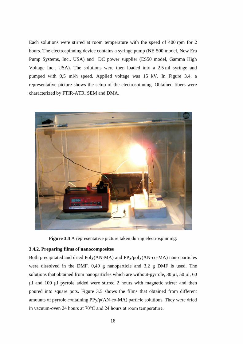
Each solutions were stirred at room temperature with the speed of 400 rpm for 2
hours. The electrospinning device contains a syringe pump (NE-500 model, New Era
Pump Systems, Inc., USA) and DC power supplier (ES50 model, Gamma High
Voltage Inc., USA). The solutions were then loaded into a 2.5 ml syringe and
pumped with 0,5 ml/h speed. Applied voltage was 15 kV. In Figure 3.4, a
representative picture shows the setup of the electrospinning. Obtained fibers were
characterized by FTIR-ATR, SEM and DMA.
Figure 3.4 A representative picture taken during electrospinning.
3.4.2. Preparing films of nanocomposites
Both precipitated and dried Poly(AN-MA) and PPy/poly(AN-co-MA) nano particles
were dissolved in the DMF. 0,40 g nanoparticle and 3,2 g DMF is used. The
solutions that obtained from nanoparticles which are without-pyrrole, 30 µl, 50 µl, 60
µl and 100 µl pyrrole added were stirred 2 hours with magnetic stirrer and then
poured into square pots. Figure 3.5 shows the films that obtained from different
amounts of pyrrole containing PPy/p(AN-co-MA) particle solutions. They were dried
in vacuum-oven 24 hours at 70°C and 24 hours at room temperature.

19
Figure 3.5 Films obtained without pyrrole addition and with different
amount pyrrole addition.

20

21
4. RESULTS AND DISCUSSION
4.1. Nanoparticle Characterization
4.1.1 SEM analysis of P(AN-co-MA) and PPy/p(AN-co-MA) nanoparticles
obtained from emulsion latexes
Nanoparticles sampled from emulsion latexes that obtained from participated
nanoparticle solvents were characterized morphologically by Scanning Electron
Microscope (LEO SUPRA 35 VP) and the samples for the SEM measurements are
coated with gold (Ion Sputter Metal Coating Device, MCM-100). Nanoparticles
were driped onto a glass surface and then dried at room temperature. After that
samples were coated with gold in order to use SEM e-beams effectively.
a) No pyrrole b) 30 ul pyrrole added
b) 50 ul pyrrole added c) 60 ul pyrrole added

22
d) The zoomed image of nanoparticles
Figure 4.1 The SEM images of both with addition of pyrrole and wihout addition of
pyrrole
Figure 4.1. shows the SEM images of P(AN-co-MA) and PPy/p(AN-co-MA)
nanoparticles obtained from emulsion latexes. Spherical structures occured by the
emulsion polymerization method, by the stirring in high rpm of magnetic stirrer.
After addition of pyrrole into the emulsion media while reaction is continuing may
provide a core-shell structure since the surfactant DBSA create a micro-reactor
vessel by providing micelle formation where the monomers are encapsulated in.
Polymers are macromolecular chains consisting of many subunits that are formed by
consecutive additions of monomer. Diblock copolymers, in particular, have two
characteristic subunit types in a single non-repeating AB pattern. [101-103]
Amphiphilic diblock copolymers consist of two regions with substantially different
solubility properties. For example, a polymer composed of a hydrophobic
poly(methyl acrylate) and a hydrophilic poly(acrylic acid) block can aggregate into
micellar structures upon introduction to an aqueous solution.[104] In this fashion, the
hydrophobic region of the amphiphilic molecule initiates micellization by collapsing
to form the core, while the hydrophilic block forms a protective shell. [105] Smaller
surfactant molecules used as detergents and emulsifiers have long been studied in
determining the size, shape, and physical properties of various micelles. [106-107]
Relatively high concentrations of surfactants have been observed for micelle
formation.[108]
Under these information’s light, it is considered that in this study hydrophobic part of
the surfactant molecules may adsorb on the produced conducting polymer, a
surfactant thus becoming a part of the resulting material. Therefore, p(AN-co-MA)

23
may be encapsulated in the DBSA miscelle by the hydrophobic tail, since the MA
monomer is hydrophobic too. Then Pyrrole may be polymerized by the adsorption on
the surface on the miscelle. As seen in the Table 4.1., nanoparticle sizes are
decreased by the addition of pyrrole first; but then increased by the increasing
amount of pyrrole added. The concentration at which a block copolymer achieves
micellization is referred to as the critical aggregation concentration (CAC).
Copolymers are more ideal for micellar applications than surfactants due to
decreased CAC requirements. [109] Lower copolymer concentrations necessary for
micelle formation were determined to be a function of dispersion, hydrogen bonding,
and electrostatic intermolecular forces associated with the hydrophobic block. [110-
112]
When the CAC is reached for a copolymer, small polymeric micelles form. The
micelles then coalesce as local concentrations of copolymer are further increased.
[113-114] Micelle dissolution can then be triggered by a change in temperature, pH,
salt concentration, or light intensity. [115-116]
Table 4.1. : P(AN-co-MA) and Ppy/ p(AN-co-MA) latex nanoparticle sizes
measured on SEM images
Nanoparticle
from latex
Added Pyrrole
Content (µl)
Particle Size
(nm)
P(AN-co-MA) 0
103,70
PPy/(AN-co-
MA)
30 83
PPy/(AN-co-
MA)
50 90
PPy/(AN-co-
MA)
60 94
4.1.2 Particle size analysis of P(AN-co-MA) and PPy/p(AN-co-MA)
nanoparticles obtained from emulsion latexes
To analyze particle size of nanoparticles, another method is used by Particle Size
Analyzer (Light Scattering) - Malvern Mastersizer Microplus Ver.2.19. Samples that
containing different amount of pyrrole addition were taken from emulsion latexes
and sent to the Organik Kimya A.Ş. in order to analyze particle size. As seen in the
Figure 4.2. the colour of latex nanoparticles that sampled from emulsion media
changes into darker by increasing pyrrole addition. This means that the

24
polymerization of pyrrole occurs aparrently. Thus, the dark blue-blackish colour of
polypyrrole is appeared sample by sample.
Figure 4.2 The colour change of latex nanoparticles that sampled from emulsion
media by increasing pyrrole addition.
By increasing amounts of polypyrrole in the structure, particles get bigger as shown
in the Table 4.2. These diameters were measured by Particle Size Analyzer and
differs from SEM images, this may be caused from the aggregation due to
electrostatic structure of polypyrrole.
According to Quajai et al, in the range of 60-90 nm Ppy nanoparticles can be
obtained by microemulsion process. It is observed that when a nanosizer is used to

25
measure the particle sizes, the average particle size is found to be in the range of 180-
1300 nm. This value is much more bigger than the measurement of SEM images, this
means Ppy particles tend to form an aggregation. The polymerization conditions
affect the aggregation degree. For instance when the SDS-doped Ppy was
synthesized at room temperature without stabilizer; high degree of aggregation was
indicated and average particle size was found 1300 nm. However, when it is
synthesized at low temperature, the particle size is observed as 180 nm. This is
because of the restricted mobility of the surfactant that leads to the desrease in the
inner volume of micelles that encapsulate the monomer and the oxidant. Reduced
micelle volume results in reduced nanoparticle size [117].
Table 4.2. : P(AN-co-MA) and PPy/ p(AN-co-MA) latex nanoparticle sizes
measured by Particle Size Analyzer
Nanoparticle from
latex
Added Pyrrole Content
(µl)
Particle Size
(nm)
P(AN-co-MA)
0 118
PPy/(AN-co-MA) 5 119
PPy/(AN-co-MA) 15 124
PPy/(AN-co-MA) 25 145
PPy/(AN-co-MA) 30 9340
PPy/(AN-co-MA) 50 9550
PPy/(AN-co-MA) 60 15500
PPy/(AN-co-MA) 150 15510
PPy/(AN-co-MA) 300 52680
4.1.3 FTIR-ATR characterization of P(AN-co-MA) and PPy/p(AN-co-MA)
nanoparticles obtained after precipitating and drying the emulsions
FTIR analysis of dried P(AN-co-MA) and PPy / p(AN-co-MA) nanoparticles after
precipitation were carried out with FTIR-ATR reflectance spectrophotometer (Perkin
Elmer, Spectrum One, with a Universal ATR attachment with a diamond and ZnSe
crystal) as seen in the Figure 4.3.

26
Figure 4.3 FTIR-ATR reflectance spectrophotometer in Electropol & Nanotech
Laboratory
4.1.3.1. FTIR-ATR characterization of p(AN-co-MA)
Powder samples were taken and analyzed. The FTIR-ATR spectra of p(AN-co-MA)
and PPy/(AN-co-MA) are shown in Figure 4.4 and it was recorded in the absorbance
mode. Peak at 3430 cm-1
shows the N-H streching from p(AN-co-MA) [118] , peak
at 1449 cm-1
refers to C-H bending [119] from p(AN-co-MA), peaks at 2954 and
1055 cm-1
are assigned to C-H streching from p(AN-co-MA) [120] [121]. The peak
at 2242 cm-1
is the characteristic of C≡N nitrile group from AN [121]. C=O
streching from MA can be seen at 1726 cm-1
as a characteristic [118]. The strong
absorption peak here is appearing in every spectrum of the copolymers is associated with
carboxyl groups The peak at 1634 cm-1
may be coming from O-H bending. [122]
Figure 4.4 FTIR-ATR spectra of p(AN-co-MA) nanoparticles
4500 4000 3500 3000 2500 2000 1500 1000 500
0,0
0,1
0,2
0,3
0,4
Ab
so
rba
nce
Wave number (cm-1)
%50 AN-%50 MA
%60 AN-%40 MA
%75 AN-%25 MA
%95 AN-%05 MA3430
2954 2242
1726
1634
1449
1199
1167

27
The graph at Figure 4.5 is the absorbance value ratio at the characteristic peaks of
AN and MA. The AN amount in the structure is increasing step by step by the
increasing feed of AN monomer to the emulsion media. As the absorbance values are
taken from the graph, the relationship between polymerization rates may be
calculated from the ratios.
50 60 70 80 90 100
0,05
0,10
0,15
0,20
0,25
0,30
0,35
0,40
0,45 2242/(2242+1726)
Ab
so
rba
nce
ra
tio
% mol of AN
Figure 4.5 The absorbance ratio of C≡N (2242) / C=O streching (1726)
4.1.3.2. FTIR-ATR characterization of PPy / p(AN-co-MA)
The characteristic peaks can be easily seen by the FTIR-ATR graphs of PPy / p(AN-
co-MA) nanoparticle powders in the Figure 4.6. The peak at 1554 cm-1
shows the PPy
ring vibration [123] and also peak at 1449 cm-1
shows the PPy ring vibration (C=C
streching) too [124]. At the 1166 cm-1 C-H in-plane deformation is observed [124].
1045 cm-1
peak refers to N-H in-plane deformation [124]. Peaks at 967 and 911 cm-
1are the =C-H out of plane vibration [125]. The appearance of the peak at 1554 cm
-
1above a certain pyrrole addition concentration is due to the Polypyrrole formation in
the structure strongly. Figure 4.7 indicates that the 1554 cm-1
peak is appearing and
increasing sample by sample as the added pyrrole amount is increased up to 300 µl.

28
Figure 4.6 FTIR-ATR spectra of PPy / p(AN-co-MA) nanoparticles by increasing
amounts of polypyrrole
Figure 4.7 The appearing peak at 1554 cm-1
due to the increasement of pyrrole
addition.
In the figure 4.8, the absorbance ratio of Polypyrrole’s characteristic peak to
Acrylonitrile’s peak refers to the increasement of polypyrrole in the structure.
4500 4000 3500 3000 2500 2000 1500 1000 500
-0,02
0,00
0,02
0,04
0,06
0,08
0,10
0,12
0,14
0,16
0,18
0,20
Ab
so
rba
nce
Wavenumber (cm-1)
no pyrrole
15 ul
50 ul
100 ul
150 ul
300 ul
1554
1449
911967
1166
1045
2000 1500 1000 500
-0,02
0,00
0,02
0,04
0,06
0,08
0,10
0,12
0,14
0,16
0,18
0,20
Ab
so
rba
nce
Wavenumber (cm-1)
no pyrrole
15 ul
50 ul
100 ul
150 ul
300 ul
1554
1449
911967
1166
1045

29
Acrylonitrile amount is held constant. The increasement at the 1553 cm-1
ring
vibration is obvious but the increasement of the 1449 cm-1
ring vibration is not clear.
This is probably because of the existence of overlapping peaks.
Figure 4.8 The 1553 and 1449 cm-1
(PPy ring vibtarion) ratio to 2243 cm-1
(C≡N
formation of AN)
Figure 4.9 The comparation of pure PPy obtained at the same emulsion conditions
without matrix of PPy / p(AN-co-MA) and P(AN-co-MA)
0 50 100 150 200 250 300
0,05
0,10
0,15
0,20
0,25
0,30
0,35
0,40
0,45
0,50
0,55
0,60
0,65
0,70
0,75
1553/(1553+2243)
1449/(1449+2243)
Ab
so
rba
nce
ra
tio
Pyrrole content
4500 4000 3500 3000 2500 2000 1500 1000 500
0,00
0,05
0,10
0,15
0,20
0,25
0,30
0,35
0,40
0,45
1045
1449
Ab
so
rba
nce
Wave number (cm-1)
no pyrrole (AN-MA)
300 ul pyrrole added AN-MA
polypyrrole
1554
1554
1449
1045

30
In the Figure 4.9, the pure PPy that obtained with the same emulsion reaction
conditions with the P(AN-co-MA) and PPy / p(AN-co-MA) particles. When we look
at the pure PPy’s characteristic peaks, we can see these peaks in the composite
nanoparticles spectrum too. This means pyrrole is successfully polymerized by one
step within the matrix: P(AN-co-MA).
4.1.4 UV-Visible Spectroscopy characterization of P(AN-co-MA) and
PPy/p(AN-co-MA) nanoparticles obtained after precipitating and drying
the emulsions
The UV-Visible Spectroscopy characterization is achieved by using the Perkin Elmer
Lambda 45 UV-Visible Spectrometer. After precipitation and drying of emulsions,
0.01 g powder nanoparticle is dissolved in 8 ml DMF and after calibration of the
spectrometer with pure DMF, the measurements were taken. In Figure 4.10 the UV-
Visible Spectrometer is seen in the Electropol&Nanotech Laboratory.
Figure 4.10 The UV-Visible Spectrometer in the Electropol&Nanotech Laboratory.
The UV-Visible spectroscopy results shows the absorbance increase by the
increasing pyrrole addition into the reaction media.0, 5, 10, 15, 25, 30, 50, 60, 100,
150, 300 microliters of pyrrole added nanoparticles were analyzed and after 150
microliter PPy added, the characteristic peak at 460 nm appears and shows the π-π*
transition band in the polypyrrole. [126] This peak appears at 150 µl and 300 µl
pyrrole added samples as seen in the Figure 4.11.

31
Figure: 4.11 The UV-Visible spectrum of pure DMF, p(AN-co-MA) and increasing
amounts of polypyrrole containing PPy/p(AN-co-MA) nanoparticles in
DMF solution.
4.1.5. The relationship between UV-Visible spectroscopy reflectance and
particle size of nanoparticles
As Bernard Van Eerdenbrugh writes in his study, UV-Visible light is a effective
method to catch and follow the micron and sub-micron particle sizes in an aqueus
medium. [127]
Scattering techniques totally suffer from the disadvantage that in order to obtain a
reliable estimate of particle size, measurements should be made at a range of
lowdisperse - phase volume fractions and should be extrapolated to infinite dilution
in order to avoid the problems encountered as a result of particle-particle
interactions. However, the dilution of a microemulsion containing a surfactant is
often problematic, due to the partitioning of the surfactant between the various
phases, which often leads either to a change in the microstructure of the system or, in
extreme cases, the disappearance of the microemulsion droplets [128]. All in all,
scattering studies on microemulsion systems are often carried out in the concentrated
microemulsion region and an appropriate model is then used to correct the results for
particle-particle interactions. [129]
300 400 500 600 700 800
0,0
0,1
0,2
0,3
0,4
0,5
0,6
0,7
0,8
0,9
1,0
1,1
1,2
1,3
1,4
1,5
1,6
1,7
424 nm
Ab
so
rba
nce
Wavelength (nm)
DMF
0 ul
5 ul
10 ul
15 ul
25 ul
30 ul
50 ul
60 ul
100 ul
150 ul
300 ul
424 nm

32
In any scenario where small (submicron) absorbing particles are present in the
medium being analyzed, caution should be exerted when using UV/Vis fiber-optics
for quantification of dissolved concentrations. [130]
As seen in the figure above, the spectrum curves does not start from the same point.
There is a probability of light reflection due to the size of the particle. The amount of
scattered and reflected particles is a function of particle size. In that sense UV-
Visible Spectroscopy can be correlated with light scattering method. If the
absorbance of a certain point is correlated with the results of particle size analysis, a
proportionality will be seen on these two kinds of characterization. Figure 4.12 and
4.13 shows the probable reflection on the spectrum and the certain point at the 325
nm to choose the absorbance values. Also the Table 4.3 indicates the proportional
increasement of particle size and absorbance at the probable reflectance point as the
Figure 4.14.
Figure 4.12 The probable reflection on the spectrum

33
Figure 4.13 The certain point to examine the reflection
Table 4.3: The comparison of the absorption at the 325 nm, pyrrole amount and
particle size
Added
Pyrrole (µl)
UV Absorbance at
325 nm
Particle Size by Particle
Size Analyzer(nm)
0 0,0678 118
5 0,0838
119
15 0,1842
124
25 0,4635
145
30 0,5429 9340
50 0,5799 9550
60 0,9846 15500
150 1,1459 15510
300 0,0678 52680

34
Figure 4.14 The proportional increasement of the particle size in relation with the
UV absorbance at 325 nm.
4.1.6. Differential scanning calorimetry analysis of p(AN-co-MA) and PPy /
p(AN-co-MA) nanoparticles
Tg values of the p(AN-co-MA) , 30 µl pyrrole added PPy / p(AN-co-MA) and 100 µl
pyrrole added PPy / p(AN-co-MA) were determined as the Figure 4.15 and Table
4.4. By the polypyrrole entrance to the structure, the stiffnes and relatively hard
processibility occurs, therefore Tg is higher at more PPy containing samples.
Sanderson et al has studied effect of process variables on the initiation temperature
and exothermic heat for the copolymerzation of acrylonitrile and methylacrylate.
According to this study, the reaction of AN-MA copolymerization gives an
exothermic peak on the DSC curves according to the stabilization process. [131] Our
results are parellel to the Sanderson’s results for AN-MA copolymers. (Effect of
process variables on the initiation temperature and exothermic heat for the
copolymerzation of acrylonitrile and methylacrylate.
0,0 0,2 0,4 0,6 0,8 1,0 1,2
-2000
0
2000
4000
6000
8000
10000
12000
14000
16000
Particle size (nm)
Pa
rtic
le s
ize
(n
m)
Absorption at 325 nm

35
Figure 4.15 The Tg values of nanocomposites as increasing order.
Table 4.4: The increasing Tg values acording to increasing pyrrole addition
Added
pyrrole(µl) Tg ( ºC)
0 77,9
30 80,7
100 82,85
4.2. Nanofiber and Film Characterizations
4.2.1. Nanofiber characterization
Nanofibers were characterized by SEM and DMA (Dynamic Mechanic Analyzer).
After nanofibers were coated with gold, the sem images were taken. Figure 4.16
shows the SEM images of no-pyrrol added, 30, 50, 60, 100 µl pyrrole added sample
nanofibers.

36
Figure 4.16 The SEM images of left to right: 0, 30, 50, 60, 100 µl pyrrole added
samples.
Table 4.5: Average diameter and standart deviation of diameters according to added
pyrrole amount
Added Pyrrole
Amount(µl)
Average
Diameter (nm)
Standard
Deviation
0 597 62
30 263 47
50 345 30
60 699 37
100 307 129

37
Table 4.5 indicates that while pyrrole addition is increased, average diameter mostly
in a range of decreasement. However the standart deviation has a minimum base
point which indicates the regularity of the fiber diameter has reach a minimum value
and then increase while pyrrole addition is increased. Figure 4.17 shows that, when
polypyrrole is appeared in the nanoparticles, this polypyrrole affects nanofibers too
and provides a porous surface to the nanofibers.
Figure 4.17 (a) is the nanofiber that not contains polypyrrole and non-porous, (e) is
the nanofiber that contains polypyrrole and porous
Also Dynamic Mechanic Analyse is observed by TA Instruments DMA Q 800.
Nanofibers were too weak to dynamically measure under stress, therefore nanofiber
sheets were bended 4 times as seen in the figure 4.18 and then measurement was
achieved. The two clamps of the DMA held the nanofiber sheet and applied a force
to measure the strength of the materisl by the terms of stress and strain However, due
to the breaking points that caused by bending, the measurement was not healthy. The
resuls are given in the graph in Figure 4.19. Young’s modulus were calculated as
stress/strain.
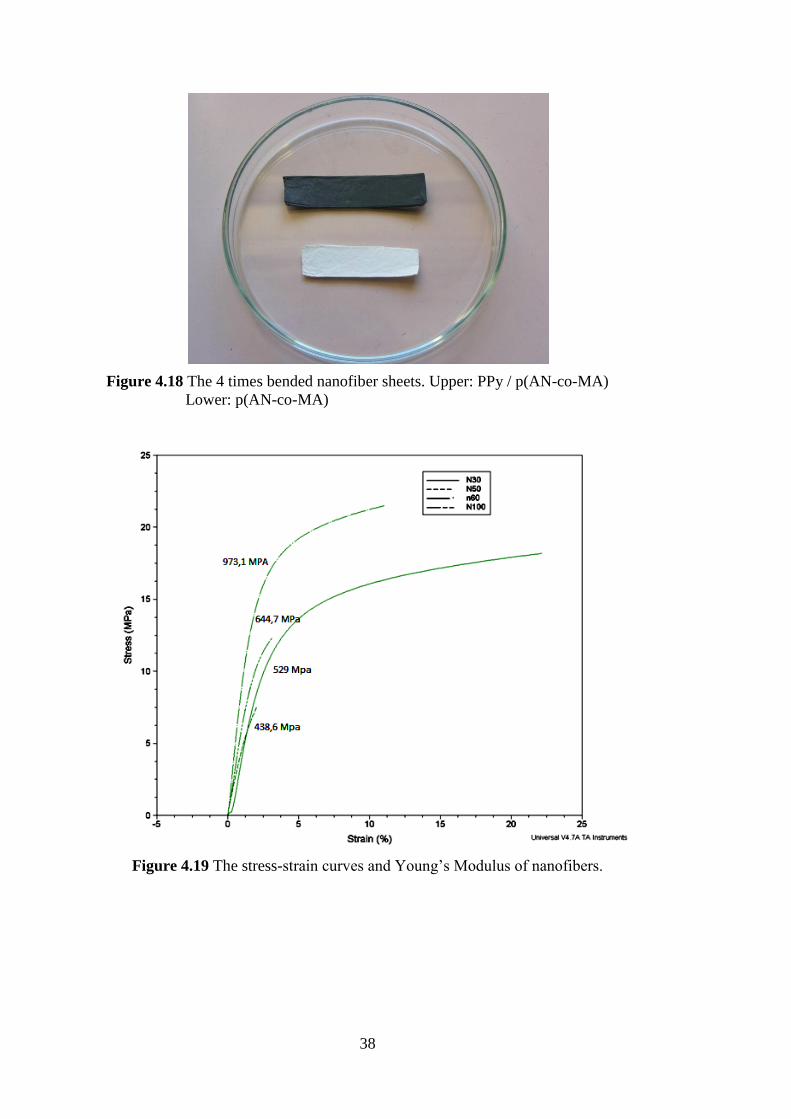
38
Figure 4.18 The 4 times bended nanofiber sheets. Upper: PPy / p(AN-co-MA)
Lower: p(AN-co-MA)
Figure 4.19 The stress-strain curves and Young’s Modulus of nanofibers.

39
4.2.2. Film characterization
The films were characterized by Dynamic Mechanic Analyzer (DMA). As
polypyrrole is brittle and stiff, when the polypyrrole formation in the structure is
increased, the elasticity and elongation of the film decreased. Therefore the Young’s
Modulus is increasing by the increasing amount of polypyrrole in the chemical
structure. This indicates that the PPy film remains all through in the glassy state and
does not exhibit any transition (glass-rubbery) in the investigated temperature range
(25 °C to 250 °C) and thus the PPy film is hard and brittle and is not soft and does
not show any flexibility in the backbone chain of the polymer. [132] The films are
shown in the Figure 4.20 as Polypyrrole formation – increasing order. And the graph
in the Figure 4.21 shows the stress-strain curves and Young’s Modulus of the films.
Figure 4.20 Films that obtained from a)30 µl b)50 µl c)60 µl d)100 µl pyrrole added
nanoparticles

40
Figure 4.21 Stress-strain curves and Young’s Modulus of the films, from highest to
lowest: obtained from 100 µl, 60 µl, 50 µl, 30 µl pyrrole added
nanoparticles.

41
5. CONCLUSIONS
To conclude this thesis by the strategic points, first of all a one-step polymerization is
achieved without any initiator addidion to the reaction media. Polypyrrole containing
nano composites were obtained from the emulsion media after the copolymerization
of p(AN-co-MA) nanoparticles, without terminating the reaction. Nano spheres were
characterized by SEM and Particle Size Analyzer, also the powder of these nano
composites were analyzed by FTIR-ATR spectroscopy, UV Visible Spectroscopy
and also (DSC) it was observed that pyrrole had successfully polymerized in the
structure. After nanoparticle characterization, nanofibers of obtained nanocomposite
were electrospinned without facing any difficulty. Polypyrrole’s characteristic
properties were appeared such as brittlenes, stiffnes and having high Young’s
modulus by characterizing the nanofibers with DMA. Also films that prepared from
the nanoparticles were examined by DMA and it was seen that by the entering of
polypyrrole in the structure, the stress that material can carry without elasticity
increased and this means the Elasticity (Young’s) modulus increased too. The
suitable nanofiber formation of the nanomaterial provides processibility to the
polypyrrole containing nano composites without brittleness.
This copolymers can be used as processible for many applications if the conductivity
studies has been carried out successfully, such as biosensors, ion selective
membranes, conductive nanocoatings, and all nanofiber flexibility needed areas.

42

43
REFERENCES
[1] Gangopadhyay, R., De, A., (2000). Chem. Mater. Vol. 12, p. 608.
[2] Zhang, T., He, Y., Wang, R., Geng, W., (2008). Sens. Actuators B 131, p. 687.
[3] Majid, K., Tabassum, R., Shah, A.F. S., Ahmad, M.L., Singla, J., (2009).
Mater. Sci. Mater. Electron. Vol 20, p. 958.
[4] Xing, S., Zhao, G., (2006). Polym. Bull. Vol. 57, p. 933.
[5] Kizilyar, L., Toppare, N., Önen, A., Yagci, Y., (1998). Polym. Bull. Vol. 40, p.
639.
[6] Ishiyama, K., Imamura, K., Arai, K.I., Magn, J., (2002). Mater. Vol. 242, p.
1163.
[7] Smyth, C., Lau,K.T., Shepherd, R.L., Diamond, D., Wu,Y., Spinks, G.M.
,Wallace, G.G., (2008). Sens. Actuators B. 129, p. 518.
[8] Yao, T., Wang, C., Lin, J,. Q. Zhang, K. J., (2009). Colloid. Interf. Sci. 338, p
573.
[9] Koezuka, H., Tsumura, A.,(1989). Synth. Met. Vol. 28, p. 753.
[10] Gao, J., Heegar, H., Lee, J.Y., Kim, C.Y., (1996). Synth. Met. Vol. 82, p. 221.
[11] Skothein, T., Elsenbaumer, A. R.L., Reynolds, J.R., (1998). Handbook of
Conducting Polymer, vol. 2, (Marcel Dekker, Inc., New
York), p. 226.
[12] Landon, P.B., Gutierrez, J., Gilleland, C.L., Jordan, L., (2007). Mater. Sci.
Mater. Electron. Vol. 18, p. 235.
[13] Chen, H., Chen, J., Liyan, K.A., Wenbo, H., Zhengping, L., Qingyue, Z.,
(2005). Chin. Sci. Bull. Vol. 50, p. 971.
[14] Liu, Y.C., Lee, H.T., Yang, S.J., (2006). Electrochim. Acta. Vol. 51,p. 3441.
[15] Roncali, J., Garnier, F., (1987). Polym. Commun. Vol. 28, p. 103.
[16] Armes, S.P., Gottesfeld, S., Beery, J.G., Garon, F., Agnew, S.F., (1991).
Polymer, vol. 32, p. 2325.
[17] Liu, C.F., Maruyama, T., Yamamoto, T., (1993). Polym. Vol. 25, p. 363.

44
[18] Khan, M.A., Armes, S.P., (2000). Adv. Mater. Vol. 12, p. 671.
[19] Huijs, F.M., Vercauteren, F.F., Ruiter, B., Kalicharan, D., Hadziioannou,
G., (1999). Synth. Met. Pp. 102.
[20] Wang, J., Sun, L., Mpoukouvalas, K., Lienkamp, K.. Lieberwirth, I.,
(2009). Adv. Mater. Vol. 21, p. 1137.
[21] Guo, L., Pei, G.L., Wang, T.J., Wang, Z.W., (2007). Colloids Surf. A
Physicochem. Eng. Asp. p. 293.
[22] Wang, Y., Shi, Y., Xu, X., Liu, F., Yao, H., Zhai, G., (2009). Colloids Surf. A
Physicochem. Eng. Asp. p. 345.
[23] Nuyken, O., and Lattermann, G., (1991) Handbook of Polymer Synthesis
Part A, 1st ed, (Kricheldorf, H. R., ed.), Marcel Dekker, New York, p.
223
[24] Warson, H. and Finch, C.A., (2001) Applications of Synthetic Resin Latices:
Fundamental chemistry of latices and applications of adhesives. John
Wiley & Sons Inc. ISBN 0-471-95268-0.
[25] Fittig, R., and Paul, L., (1887) makale adı, Justus Liebigs Ann. Chem., 188, p.
55.
[26] Fittig, R., and Engelhorn, F. R., (1880) makale adı, Justus Liebigs Ann.
Chem., 200: 70.
[27] Kahlbaum, G. W. A., (1880) Über polymere Acrylsäuremethylester, Ber.
Dtsch. Chem. Ges., vol. 13, p.2348.
[28] Röhm, O., (1901) On the Polymerization Products of Acrylic Acid, Ph.D.
thesis.
[29] Röhm, O., (1914) U.S. 1,121,134; CA (1914), vol: 09, 395 A.
[30] Barker, A. L., and Skinner, G. S., (1924) J. Am. Chem. Soc., vol. 46, 403.
[31] Riddle, E. H., (1954) Monomeric Acrylic Esters, Reinhold, New York.
[32] Kautter, C. T., (1975) Plastics Handbook, Polymethacrylate
(Polymethacrylates) Kunststoff Handbuch, Vol. 9, p. 1. Edited by R.
Vieweg and F. Esser. Carl Hanser Verlag, München.
[33] Kine, B. B., and Novak, R. W., (1985) Encyclopedia of Polymer Science and
Engineering, 2nd
ed., (Mark, H. F., Bikales, N. M., Overberger, C. G.,
and Menges, G., eds.), p. 234. Wiley, New York.
[34] Charles E. Carraher, Jr., (2003) Giant molecules; Essential Materials for
everyday living and problem solving, 2nd
Ed. John Wiley & Sons Inc.
ISBN 0-471-27399-6.
45
[35] Thompson, L. F., C. G. Willson, and J. M. J. Frechet., (1984) Materials for
Microlithography: Radiation-Sensitive Polymers, American Chemical
Society, vol. 266, pp 5026–5026.
[36] Htoo, M. S., (1989) Microelectronic Polymers, Marcel Dekker, Inc., New
York..
[37] Gonzalez, I., Asua, J. M., and Leiza J. R., (2007) The role of methyl
methacrylate on branching and gel formation in the emulsion
copolymerization of BA/MMA, Polymer, vol.48, pp 2542-2547.
[38] Semegen, S. T., Encyclopedia of Physical Science and Technology, Polymers,
3rd ed., pp. 395-405, Academic Press.
[39] Liang Y., Ji L., Guo B., Lin Z., Yao Y.F., Li Y., Alcoutlabi M., Qiu Y.,
Zhang, X.,(2011). Preparation and electrochemical characterization of
ionicconducting lithium anthanum titanate oxide/polyacrylonitrile
submicron composite fiber- based lithium-ion battery separators. J
Power Sources;196, pp. 436–41.
[40] Schildknecht CE., (1952). Vinyl and related polymers; their preparations,
properties and applications in rubbers, plastics and in medical and
industrial arts. New York: Wiley-Interscience. p. 3878.
[41] Perepelkin K.E., Klyuchnikova N.V., Kulikova N.A., (1989) Experimental
evaluation of man-made fibre brittleness. Fibre Chem. 21: 145–8.
[42] Rahaman M.S.A., Ismail A.F., Mustafa A. (2007). A review of heat treatment
on polyacrylonitrile fiber. Polym Degrad Stab. 92, pp.1421–32.
[43] Litmanovich A.D., Plate N.A., (2000). Alkaline hydrolysis of polyacrylonitrile;
on the reaction mechanism. Macromol Chem Phys. 201, pp.2176–80.
[44] Khajuria A., Balaguru P.N., (1992). Plastic shrinkage characteristics of fiber
reinforced cement composites. In: Swamy RN, editor. Fibrereinforced
cement composites. London: Routledge, Taylor & Francis;. p. 82–90.
[45] Bai Y.J., Wang C.G., Lun N., Wang Y.X., Yu M.J., Zhu, B. HRTEM
microstructures.
[46] Nataraj S.K., (2012). Polyacrylonitrile-based nanofibers - A state-of-the-art
review, Progress in Polymer Science vol. 37 pp.487– 513.
[47] Curran, D., Grimshaw, J. and Perera, S. D., Chem. Soc. Rev., (1991), 20, 1;
Malli, S., Ind. J. Chem., 1994, 33A, p. 524.
[48] Shirakawa, H., Louis, E., MacDiarmid, A., Heeger, A., (1977). Synthesis of
electrically conducting organic polymers: halogen derivatives of
polyacetylene, (CH)x. Chem. Commun. pp. 578–580.
[49] Tour, J.M., (2000) Molecular wires for electronic applications. Polym. News
25, pp. 329– 336.

46
[50] Maw, S., Smela, E., Yoshida, K., Sommer-Larsen, P., Stein, R.B., (2001).
The effects of varying deposition current density on bending
behaviour in PPy(DBS)- actuated bending beams. Sensors Actuators
A 89, pp. 175–184.
[51] Sonmez, G., Scottland, P., Zong, K., Reynolds, J.R., (2001). Highly
transmissive and conductive poly[(3,4-alkylenedioxy)pyrrole-2,5-
diyl] (PXDOP) films prepared by air or transition metal catalyzed
chemical oxidation. J. Mater. Chem. 11, pp. 289–294.
[52] Ferraris, J.P., Brotherston, I.D., Loveday, D.C., Mudigonda, D.S.K., Li, L.,
(1999).Type III electrochemical capacitors based on poly(3-
phenylthiophene) derivatives. Proc. Electrochem. Soc. 98, pp. 671–
682.
[53] Lovinger, A.J., Bao, Z., Katz, H.E., Dodabalapur, A., (1999). Structural,
morphological and orientational requirements for high-
performance polymeric and organic thin-film transistors. Polym.
Mater. Sci. Eng. 81, pp. 234–235.
[54] Gratzel, M., (2001). Molecular photovoltaics that mimic photosynthesis. Pure
Appl. Chem. 73, pp. 459–467.
[55] MacDiarmid, A.G., (1985). Short Course on Conductive Polymers. SUNY,
New Platz, NY.
[56] Zarras, P., Irvin, J.A., (2003). Electrically active polymers. In: Encyclopedia
of Polymer Science and Technology, 3rd Edition. John Wiley &
Sons, New York.
[57] Epstein, A.J., (1997). Electrically conducting polymers: science and
technology. MRS Bull. 22 (6), pp. 16–23.
[58] Ondarcuhu T., Joachim C., (1998). Drawing a single nanofibre over hundreds
of microns. Europhys Lett. 42(2), pp. 215–20.
[59] Feng, L., Li, S., Li, H., Zhai, J., Song, Y., Jiang, L., et al. (2002). Super-
Hydrophobic Surface of Aligned Polyacrylonitrile Nanofibers. Angew
Chem Int Ed. 41(7) pp. 1221–3.
[60] Martin, C.R., (1996). Membrane-based synthesis of nanomaterials. Chem
Mater, vol. 8:1739, p. 46
[61] Ma P.X., Zhang R., (1999). Synthetic nano-scale fibrous extracellular matrix. J
Biomed Mat Res vol. 46, pp.60–72.
[62] Liu G.J., Ding J.F., Qiao L.J., Guo A., Dymov B.P., Gleeson J.T., et al.
(1999). Polystyrene-block poly (2-cinnamoylethyl methacrylate)
nanofibers- Preparation, characterization, and liquid crystalline
properties. Chem-A European J. Vol: 5-2740, p.9.

47
[63] Whitesides G.M., Grzybowski B., (2002). Self-assembly at all scales. Science
295. pp. 2418–21.
[64] Deitzel J.M, Kleinmeyer J., Hirvonen J.K., Beck T.N.C., (2001). Controlled
deposition of electrospun poly(ethylene oxide) fibers. Polymer, vol.
42:8163, p.70.
[65] Fong H., Reneker D.H., (2001).Electrospinning and formation of nanofibers.
In: Salem D.R., editor. Structure formation in polymeric fibers.
Munich: Hanser; p. 225–46.
[66] Formhals A. (1934).US patent 1,975,504,
[67] Formhals A. (1939).US patent 2,160,962,
[68] Formhals A. (1940).US patent, 2,187,306,
[69] Formhals A. (1943).US patent, 2,323,025,
[70] Formhals A., (1944). US patent, 2,349,950,
[71] Baumgarten P.K., (1971). Electrostatic spinning of acrylic microfibers of
Colloid and Interface Science vol.9. pp.36-71.
[72] Taylor G.I., (1969). Electrically driven jets. Proc R Soc London, Ser A.
313:453, p.75.
[73] Doshi J., Reneker D.H., (1995). Electrospinning process and applications of
electrospun fibers. J Electrostatics. Vol. 35(2-3), pp. 51–60.
[74] Kenawy E.R., Layman J.M., Watkins J. R., et al. (2003). Electrospinning Of
Poly(Ethylene-Co-Vinyl Alcohol) Fibers. Biomaterials, vol. 24(6), pp.
907―913.
[75] Stankus J. J., Guan J., Wagner W. R., (2004), Fabrication of biodegradable
elastomeric scaffolds with sub-micron morphologies. J Biomed
Mater Res Part A, vol. 70A(4), pp. 603―614
[76] Bovey, F.A., Kolthoff, I.M., Medalia, A.I., Meehan, E.J. (1965). Emulsion
polymerization. New York: Interscience Publishers.
[77] Blakely, D.C. (1975). Emulsion polymerization. Theory and practice. London:
Applied Science.
[78] Eliseeva, V.I., Ivanchev, S.S., Kuchanov, S.I., Lebedev, A.V., (1981).
Emulsion polymerization and its applications in industry. New York:
Consultants Bureau.
[79] Barton, J, Capek, I. (1994.) Radical polymerization in disperse systems. New
York: Ellis Horwood.

48
[80] Gilbert, R.G. (1995.) Emulsion polymerization: a mechanistic approach.
London: Academic Press.
[81] Fitch, R.M. (1997.) Polymer colloids: a comprehensive introduction. London:
Academic Press.
[82] Verwey, E.J.W., Overbeek, J.Th.G., (1943). Theory of the stability of
lyophobic colloids. New York: Elsevier.
[83] (2006) , Emulsion polymerization mechanisms and kinetics, C.S. Chern, Prog.
Polym. Sci. 31 p. 443–486
[84] El-Aasser, M.S., Miller C.M., (1997).nPreparation of latexes using
miniemulsions. In: Asua JM, editor. Polymeric dispersions. Principles
and applications. Dordrecht: Kluwer, p.109–26.
[85] Sudol, E.D., El-Aasser, M.S. (1997). Miniemulsion polymerization. In: Lovell
PA, El-Aasser MS, editors. Emulsion polymerization and emulsion
polymers. Chichester: Wiley, p. 699–722.
[86] Capek, I., Chern, C.S. (2001). Radical polymerization in direct miniemulsion
systems. Adv Polym Sci, vol. 155, p. 101–65.
[87] Antonietti, M., Landfester, K., (2002). Polyreactions in miniemulsions. Prog
Polym Sci vol. 27, p. 689–757.
[88] Asua, J.M., (2002). Miniemulsion polymerization. Prog. Polym Sci vol: 27:1, p.
283–346.
[89] Candau, F., (1992). Polymerization in microemulsions. In: Paleos CM, editor.
Polymerization in organized media. Philadelphia: Gordon & Breach.
p. 215–82.
[90] Candau ,F., (1999). Polymerization in microemulsions. In: Kumar P, Mittal
KL, editors. Handbook of microemulsion science and technology.
New York: Marcel Dekker; p. 679–712.
[91], Capek I., (1999). Radical polymerization of polar unsaturated monomers in
direct microemulsion systems. Adv Colloid Interface Sci. Vol. 80. p.
85–149.
[92] Capek, I., (1999). Microemulsion polymerization of styrene in the presence of
anionic emulsifier. Adv Colloid Interface Sci vol. 82:2, p.53–73.
[93] Harkins, W. D. (1945). A general theory of the reaction loci in emulsion
polymerization. J Chem Phys vol. 13:38 p. 1–2.
[94] Harkins, W.D. (1946) A general theory of the reaction loci in emulsion
polymerization. II. J Chem Phys,vol:14:4, p. 7–8.
[95] Harkins, W.D. (1947). A general theory of the mechanism of emulsion
polymerization. J Am Chem Soc, vol. 69:14, p. 28–44.

49
[96] Smith, W.V., Ewart R.H. (1948).Kinetics of emulsion polymerization. J Chem
Phys vol. vol. 16: 59, 2–9.
[97] Smith, W.V., (1948). The kinetics of styrene emulsion polymerization. J Am
Chem Soc vol. 70:3, p. 695–702.
[98] Smith, W.V., (1949). Chain initiation in styrene emulsion polymerization. J Am
Chem Soc. 71:4077–82.
[99] Gardon, J.L., (1968). Emulsion polymerization. I. Recalculation and extension
of the Smith–Ewart theory. J Polym. Sci. A:1. vol. 6, p. 623–41.
[100] Gardon, J.L., (1968). Emulsion polymerization. II. Review of experimental
data in the context of the revised Smith–Ewart theory. J Polym. Sci.
A:1 vol. 66, p. 43–64.
[101] Kwon, G., Naito, M., Yokoyama, M., Okano, T., Sakurai, Y., Kataoka, K.
(1993). Micelles Based on AB Block Copolymers of
Poly(ethylene oxide) and Poly(β- benzyl L-aspartate). Langmuir., vol.
9, p. 945-949.
[102] Perrier, S., Takolpuckdee, P., Mars, C. A. (2005). Reversible Addition-
Fragmentation Chain Transfer Polymerization: End Group
Modification for Functionalized Polymers and Chain Transfer Agent
Recovery. Macromolecules. Vol. 38, p. 2033-2036.
[103] Bader, H., Ringsdorf, H., Schmidt, B. (1984). Water soluble polymers in
medicine. Ang. Makromol. Chem. Vol. 123, p. 457-485.
[104] Kataoka, K., Harada, A., Nagasaki, Y. (2001). Block Copolymer micelles
for drug delivery: design, characterization and biological
significance. Adv. Drug Deliver Rev. Vol. 47, p. 113-131.
[105] Mukerjee, P., Mysels, K. J. (1971). Critical Micelle Concentrations of
Aqueous Surfactant Systems; ADD095344; DTIC.
[106] Robson, R. J., Dennis, E. A. (1977). The Size, Shape, and Hydration of
Nonionic Surfactant Micelles. Triton X-100. J. Phys. Chem. Vol. 81,
p. 1075-1078.
[107] Cabane, B., Duplessix, R. (1982). Organization of surfactant micelles
adsorbed on a polymer molecule in water; a neutron scattering
study. J. Physique. Vol. 43, p. 1529-1542.
[108] Kile, D. E., Chiou, C. T. (1989). Water Solubility Enhancements of DDT and
Trichlorobenzene by Some Surfactants Below and Above the Critical
Micelle Concentration. Environ. Sci. Technol. Vol. 23, p. 832-838.
[109] Jain, N., Trabelsi, S., Guillot, S., McLoughlin, D., Langevin, D., Letellier,
P.,Turmine, M. (2004). Critical Aggregation Concentration in Mixed
Solutions of Anionic Polyelectrolytes and Cationic Surfactants.
Langmuir. Vol. 20, p. 8496-8503.

50
[110] Holmberg, K., Jonsson, B., Kronberg, B., Lindman, B. (2003).
Intermolecular Interactions. In Surfactants and Polymers in Aqueous
Solution; Ed.; Wiley:England, p 157.
[111] Kataoka, K., Ishihara, A., Harada, A., Miyazaki, H. (1998). Effect of
secondary structure of poly(LLysine) segments on the micellization of
poly(ethylene glycol)-poly(L-Lysine) block copolymer partially
substituted with hydrocinnamoyl-group at the N α-position in aqueous
milieu. Macromolecules. Vol. 31, p. 6071-6076.
[112] Kabanov, A. V., Vinogradov, S. V., Suzdaltseva, Y. G., Suzdaltseva, V. Y.,
Alakhov, V. Y. (1995). Water soluble block polycations as Carriers
foroligonucleotide delivery. Bioconjug. Chem, vol. 6, p.639-643.
[113] Yu, Z., Zhao, G. (1989).The physicochemical properties of aqueous mixtures
of cationic-anionic surfactants: II. Micelle growth pattern of
equimolar mixtures. J. Colloid Interface Sci. Vol. 130, p. 421-431.
[114] Lam, Y. M., (2003). Goldbeck-Wood, G. Mesoscale simulation of block
copolymers in aqueous solution: parameterisation, micelle growth
kinetics and the effect of temperature and concentration morphology.
Polymer. Vol. 44, p. 3593-3605.
[115] Schmaljohann, D. (2006). Thermo- and pH-responsive polymers in drug
delivery. Adv. Drug. Deliv. Rev. Vol 58, p. 1655-1670.
[116] Chung, J. E., Yokoyama, M., Yamato, M., Aoyagi, T., Sakurai, Y., Okano,
T.(1999). Thermoresponsive drug delivery from polymeric micelles
constructed using block copolymers of poly(N-isopropylacrylamide)
and poly(butylmethacrylate). J. Control. Release. Vol. 62, p. 115.
[117] Quajai, S., At al. (2008). Synthesis of Highly Conductive Polypyrrole
Nanoparticles via Microemulsion Polymerization. Journal of Metals,
Materials and Minerals, Vol.18 No:2 p.27-31.
[118] Han N. Et al. (2010).Various Comonomers in Acrylonitrile Based
Copolymers: Effects on Thermal Behaviour. Iranian Polymer Journal
vol. 19 (4), pp 243-253.
[119] O. P. Bahl, et al. (1977). Recent Advances in Carbon Fiber technology, J. Of
Scientific and Industrial Research, vol. 38, Oct. pp 537-554.
[120] J. Mittal, et al. (1994). IR studies of PAN Fibers Thermally Stabilized at
Elevated Temperatures, Carbon, vol. 32, 6, pp 1133-1136.
[121] Xu et al. (2003). Synthesis and Properties of Exfoliated Poly(methyl
methacrylate coacrylonitrile)/ Clay Nanocomposites via Emulsion
Polymerization. Macromolecular Research, Vol. 11, No. 6, pp 410-
417.

51
[122] Farsani, R.E. et al, (2009). FT-IR Study of Stabilized PAN Fibers for
Fabrication of Carbon Fibers, World Academy of Science,
Engineering and Technology, p. 50.
[123] Zhang, X. et al. (2008). Preparation And Enhanced Capacitance of Core–Shell
Polypyrrole / Polyaniline Composite Electrode For Supercapacitors.
Journal of Power Sources vol. 176, p 403–409.
[124] Eisazadeh, H. (2007).Studying the Characteristics of Polypyrrole and its
Composites. World Journal of Chemistry vol. 2 (2), pp 67-74.
[125] Kassim, A. et al. (2006). The Pacific Journal of Science and Technology, vol.
7, p 16.
[126] Ouajai, S. et al. (2008). Synthesis of Highly Conductive Polypyrrole
Nanoparticles via Microemulsion Polymerization. Journal of Metals,
Materials and Minerals, Vol.18 No.2 pp.27-31.
[127] Eerdenbrugh, B.V. (2011). Influence of Particle Size on the Ultraviolet
Spectrum of Particulate-Containing Solutions: Implications for In-Situ
Concentration Monitoring Using UV/Vis Fiber-Optic Probes. Pharm
Res 28:1643–1652.
[128] Hou M.J., Kim M, Shah DO. (1988). A light-scattering study on the droplet
size and interdroplet interaction in microemulsions of AOT-oil-water
system. J Colloid Interface Sci.123:398-412.
[129] Lawrence, J. et al. (2000). Particle Size Analysis of Concentrated
Phospholipid Microemulsions: I. Total Intensity Light Scattering.
AAPS Pharmsci, vol. 2(2) article 1.
[130] Quajai, S. et al. (2008). Synthesis of Highly Conductive Polypyrrole
Nanoparticles via Microemulsion Polymerization. Journal of Metals,
Materials and Minerals, Vol.18 No:2 pp.27-31.
[131] Sanderson, R. D., Sadiku, E. R. (2010). UNESCO Associated Centre for
Macromolecules and Materials Science, Department of Chemistry,
Matieland, Republic of South Africa.
[132] Mahmud, E., Kassim, A., (2011). Organic Conductor Films: Fabrication and
Characterization. IJFPS, Vol.1, No.1, p. 28-32.

52

53
CURRICULUM VITAE
Name Surname: Yasemin Yerlikaya
Place and Date of Birth: Bornova / 29.05.1987
E-Mail: [email protected] / [email protected]
B.Sc.: Istanbul Technical University / Textile Engineering
M.Sc. : Istanbul Technical University / Nano Science & Nano Engineering
Professional Experience:
01.2013 – Still : Turkish Exporters’ Assembly / TURQUALITY® Project
Specialist
03.2012 – 01.2013 : Istanbul Textile and Apparel Exporters’ Association /
TURQUALITY® Project Specialist
03.2011 - 09.2011 : Realkom A.Ş. / R & D Engineer
PUBLICATIONS/PRESENTATIONS ON THE THESIS
Yerlikaya Y., Sarac A. S., 2012: Nanofibers and Characterizations of
Polypyrrole /Poly(Acrylonitrile-co-Methylacrylate) Composites, NANOSEA
2012 4th International Conference on Nano-Structures Self Assembly, 25-29
June 2012, S. Margherita di Pula, Sardinia, ITALY