Embed Size (px)
Citation preview
i
Thesis Advisor: Prof. Dr. İbrahim ÖZKOL
June, 2018
ISTANBUL TECHNICAL UNIVERSITY FACULTY OF AERONAUTICS AND ASTRONAUTICS
GRADUATION PROJECT
Farid BABAKHANLI
Antonov An-70 Propeller design
ii
Thesis Advisor: Prof. Dr. İbrahim ÖZKOL
June, 2018
ISTANBUL TECHNICAL UNIVERSITY FACULTY OF AERONAUTICS AND ASTRONAUTICS
GRADUATION PROJECT
Farid BABAKHANLI
Antonov An-70 Propeller design
iii
Farid Babakhanli, student of ITU Faculty of Aeronautics and Astronautics with
student ID 110110904, successfully defended the graduation entitled “ Antonov An-
70 Propeller Design ”, which he prepared after fulfilling the requirements specified in
the associated legislations, before the jury whose signatures are below.
Thesis Advisor: Prof. Dr. İbrahim Özkol ...........................
İstanbul Technical University
Jury Members: Prof. Dr. Metin Orhan Kaya .............................
İstanbul Technical University
Yrd.Doç.Dr. Hayri Acar ..............................
İstanbul Technical University
Date of Submission : 28 May 2018
Date of Defense : 11 June 2018

4
To my family,
5
Contents 1. Introduction ................................................................................................................................... 6
2. Prestudy ............................................................................................................................................. 7
2.1 Specifivations Antonov An-70 ....................................................................................................... 8
3. GENERAL CONCEPTS ABOUT PERVANCE .......................................................................... 11
3.1 Constant and Variable-Pirch Propeller ....................................................................................... 14
3.2 Fundamental Relationships of Propeller Rotation ..................................................................... 15
4. Properties and selection of the propeller ...................................................................................... 17
4.1 Advence ratio.............................................................................................................................. 19
4.2 Definition of Power adn Thrust –Related Coefficients ................................................................ 19
4.3 Propeller Effiency ....................................................................................................................... 20
5. BLADE ELEMENT THEORY ..................................................................................................... 20
5.1 Formulation ............................................................................................................................... 21
Figure: 1 Turbine Engine ..................................................................................................................... 6
Figure: 2 Antonov An-70 ...................................................................................................................... 7
Figure: 3 Antonov An-70 Propller ..................................................................................................... 10
Figure: 4 ............................................................................................................................................... 12
Figure: 5 ............................................................................................................................................... 13
Figure: 6 ............................................................................................................................................... 14
Figure: 7 ............................................................................................................................................... 15
Figure: 8 ............................................................................................................................................... 16
Figure: 9 ............................................................................................................................................... 21
Figure: 10 ............................................................................................................................................. 22
Table: 1 ................................................................................................................................................. 11
Table: 2 ................................................................................................................................................. 18
6
1. Introduction
Wright brothers, inventors, and aviation predecessors (1903), which performed the first
powerful, continuous and controlled flight of the plane. Wilbur Wright (16 April 1867,
Millville, Indiana, USA - May 30, 1912, Dayton, Ohio) and his brother Orville Wright
(August 19, 1871, Dayton - January 30, 1948, Dayton) 1905). If your aircraft is a propeller-
driven aircraft, it means a lot of things. The propeller (s) creates the propulsion needed to
move the airplane and allow the air to flow over the wings to allow the aircraft to advance in
the air. The propeller blades are designed like the wings of a plane. It is the airfoils that make
up the lift. When it returns, the blades act like mini-wings that accelerate the air-generating
elevator. The propeller elevator is often referred to as propeller propulsion and moves
horizontally, as opposed to the vertical propulsion that the blades create. Turboprop propellers
are driven by a gas turbine engine. Gas turbine engines are more commonly known as jet
engines. Turboprop engines have a like normal jet engine. Like other jet enines, it has
compressor, combustion, chamber and turbines. However, in contrast to normal jet engines
where the turbine is used to generate a backward force to generate forward thrust, the turbine
is used to turn the turbine propeller and compressor assembly. They are creating some
forward thrust by Newton's third law, but it can be considered that it is very small. It is the
propeller that makes up almost all of the thrust. The propeller is not directly twisted by the
turbine, but has been passed through a reduction gear to ensure that the propeller passes the
required optimum RPM. A propeller that rotates very quickly is very inefficient in terms of
both performance and structure when it comes to speed of sound.
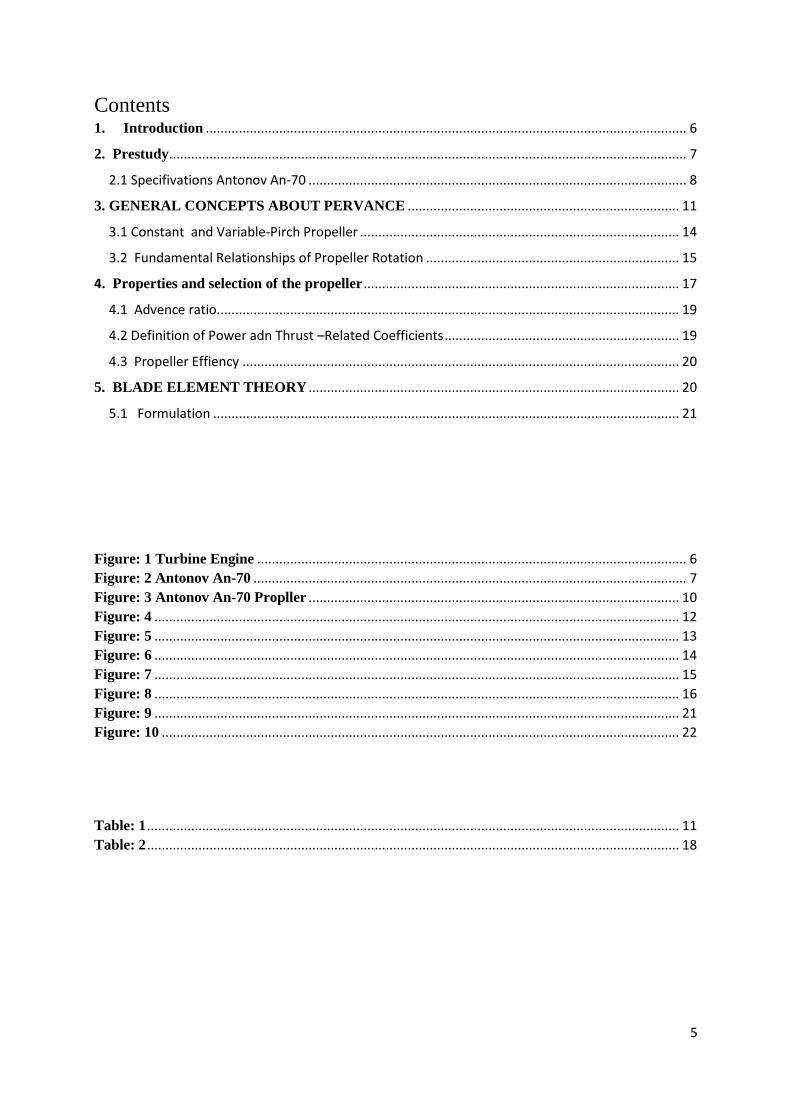
Here, the turbine that drives the propeller is completely independent of the gas generator
section. This turbine is accomplished by the force exerted by the gases produced in the gas
generator section. Its advantages include simpler design and operational flexibility. One of
these requires less power than a fixed turbine.
Figure: 1 Turbine Engine
PT-6 free turbine engine. At top, the gas generator is coloured in blue while the power
section is coloured red.
7
All that is required to operate the propeller is simply to be moved by accelerated gas in red
turbines and blue turbines. Because they continue to be used on cargo planes with over 100
tons of weight, both due to the widespread use of small aviation in general aviation, the
propellers are still up to date and perhaps even seem likely to increase the percentage of
aviation use in the near future. There are some well known examples for turboprop cargo and
military aircrafts. Hercules C-130 which is manufactured by United States Air Force, Airbus
A400M is made by Airbus and Antonov An-70 which is made by Ukraine (Antonov Design
Bureau).
2. Prestudy
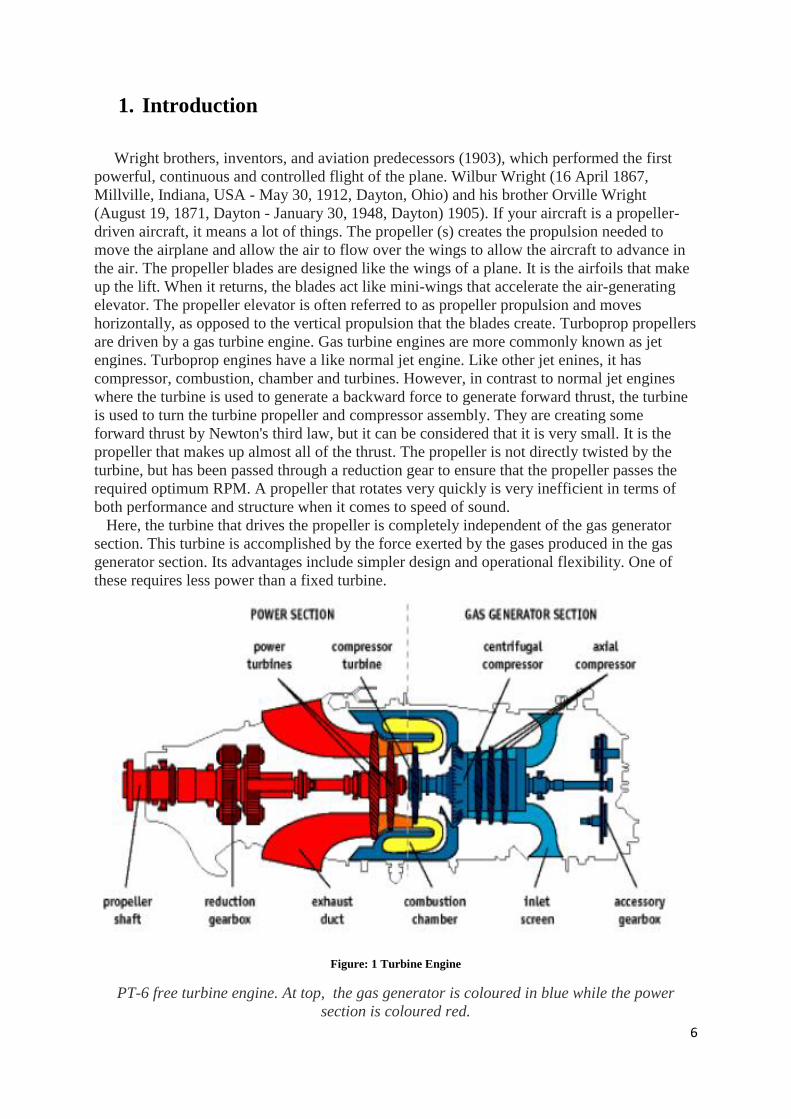
In this project , a propeller at the base level will be designed and analyzed based
on the parameters of the Ukrainian Antonov An-70 military transport aircraft and
Ivchenko-Progress ZMKB D-27 the propeller of this aircraft. Below is some
information about the Antonov An-70 that will be used in this project.
Figure: 2 Antonov An-70
8
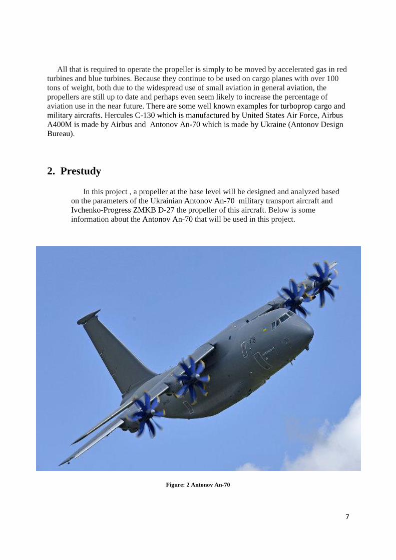
2.1 Specifivations Antonov An-70
In this work, the propeller design will be based on the Antonov An-70 aircraft and the
Progress D-27 propeller that this aircraft will have, so that a plane with a maximum take-off
weight of 135-145 tonnes will be designed with a powerful propeller. First of all it needs to
look at some parameters of the Antonov An-70 plane
9
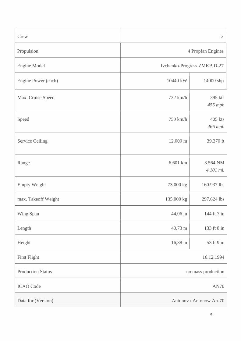
Crew 3
Propulsion 4 Propfan Engines
Engine Model Ivchenko-Progress ZMKB D-27
Engine Power (each) 10440 kW 14000 shp
Max. Cruise Speed 732 km/h 395 kts
455 mph
Speed 750 km/h 405 kts
466 mph
Service Ceiling 12.000 m 39.370 ft
Range 6.601 km 3.564 NM
4.101 mi.
Empty Weight 73.000 kg 160.937 lbs
max. Takeoff Weight 135.000 kg 297.624 lbs
Wing Span 44,06 m 144 ft 7 in
Length 40,73 m 133 ft 8 in
Height 16,38 m 53 ft 9 in
First Flight 16.12.1994
Production Status no mass production
ICAO Code AN70
Data for (Version) Antonov / Antonow An-70
10
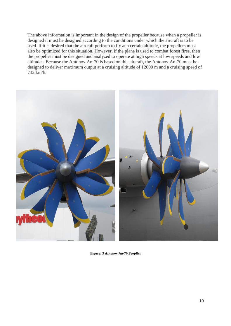
The above information is important in the design of the propeller because when a propeller is
designed it must be designed according to the conditions under which the aircraft is to be
used. If it is desired that the aircraft perform to fly at a certain altitude, the propellers must
also be optimized for this situation. However, if the plane is used to combat forest fires, then
the propeller must be designed and analyzed to operate at high speeds at low speeds and low
altitudes. Because the Antonov An-70 is based on this aircraft, the Antonov An-70 must be
designed to deliver maximum output at a cruising altitude of 12000 m and a cruising speed of
732 km/h.
Figure: 3 Antonov An-70 Propller
11
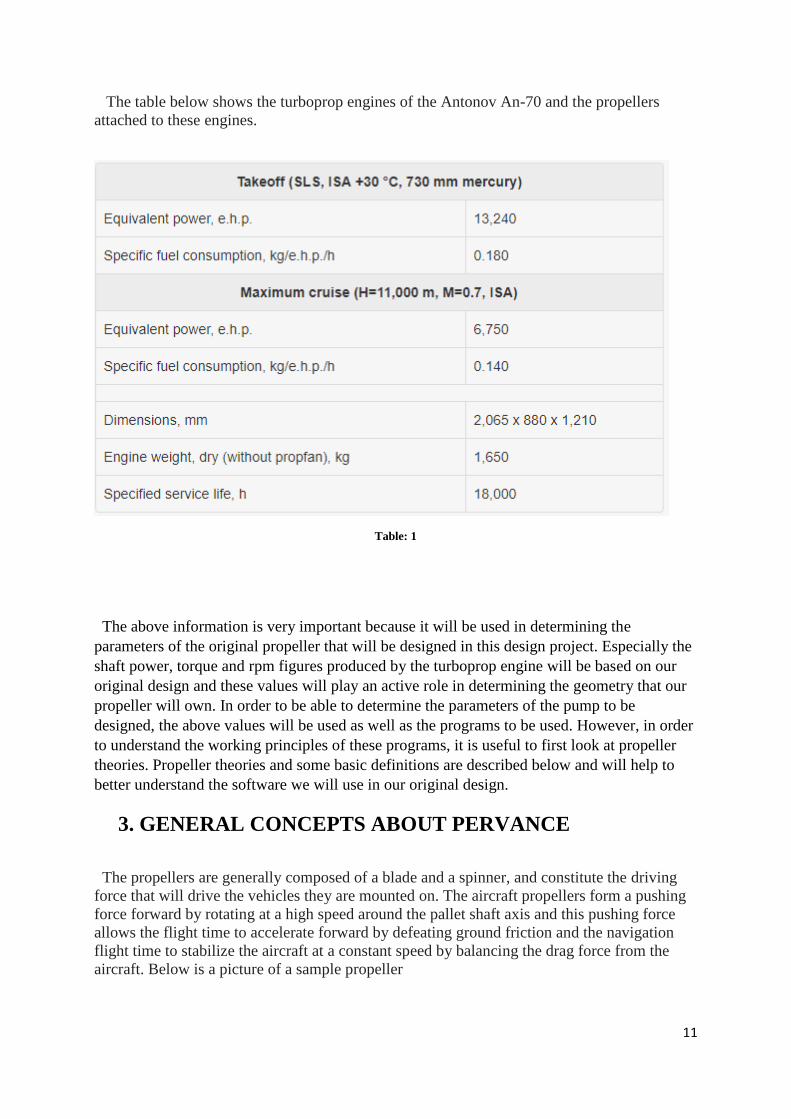
The table below shows the turboprop engines of the Antonov An-70 and the propellers
attached to these engines.
Table: 1
The above information is very important because it will be used in determining the
parameters of the original propeller that will be designed in this design project. Especially the
shaft power, torque and rpm figures produced by the turboprop engine will be based on our
original design and these values will play an active role in determining the geometry that our
propeller will own. In order to be able to determine the parameters of the pump to be
designed, the above values will be used as well as the programs to be used. However, in order
to understand the working principles of these programs, it is useful to first look at propeller
theories. Propeller theories and some basic definitions are described below and will help to
better understand the software we will use in our original design.
3. GENERAL CONCEPTS ABOUT PERVANCE
The propellers are generally composed of a blade and a spinner, and constitute the driving
force that will drive the vehicles they are mounted on. The aircraft propellers form a pushing
force forward by rotating at a high speed around the pallet shaft axis and this pushing force
allows the flight time to accelerate forward by defeating ground friction and the navigation
flight time to stabilize the aircraft at a constant speed by balancing the drag force from the
aircraft. Below is a picture of a sample propeller
12
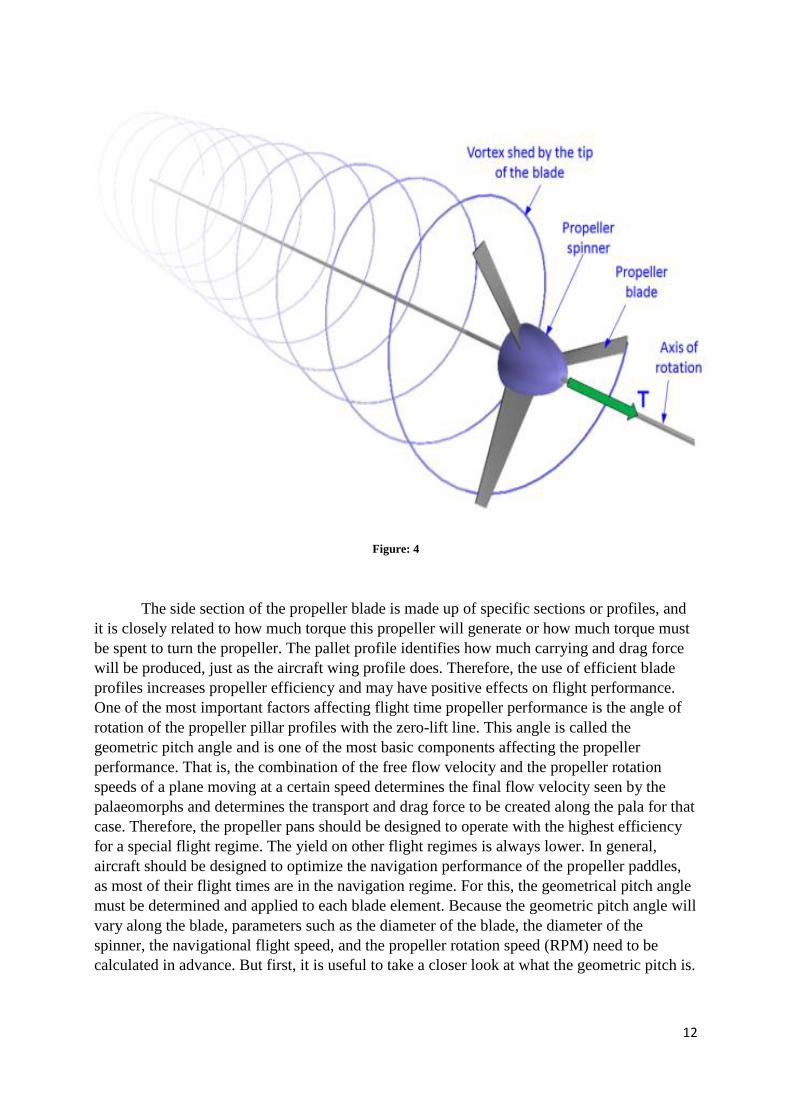
Figure: 4
The side section of the propeller blade is made up of specific sections or profiles, and
it is closely related to how much torque this propeller will generate or how much torque must
be spent to turn the propeller. The pallet profile identifies how much carrying and drag force
will be produced, just as the aircraft wing profile does. Therefore, the use of efficient blade
profiles increases propeller efficiency and may have positive effects on flight performance.
One of the most important factors affecting flight time propeller performance is the angle of
rotation of the propeller pillar profiles with the zero-lift line. This angle is called the
geometric pitch angle and is one of the most basic components affecting the propeller
performance. That is, the combination of the free flow velocity and the propeller rotation
speeds of a plane moving at a certain speed determines the final flow velocity seen by the
palaeomorphs and determines the transport and drag force to be created along the pala for that
case. Therefore, the propeller pans should be designed to operate with the highest efficiency
for a special flight regime. The yield on other flight regimes is always lower. In general,
aircraft should be designed to optimize the navigation performance of the propeller paddles,
as most of their flight times are in the navigation regime. For this, the geometrical pitch angle
must be determined and applied to each blade element. Because the geometric pitch angle will
vary along the blade, parameters such as the diameter of the blade, the diameter of the
spinner, the navigational flight speed, and the propeller rotation speed (RPM) need to be
calculated in advance. But first, it is useful to take a closer look at what the geometric pitch is.
13
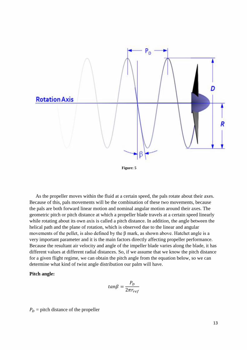
As the propeller moves within the fluid at a certain speed, the pals rotate about their axes.
Because of this, pals movements will be the combination of these two movements, because
the pals are both forward linear motion and nominal angular motion around their axes. The
geometric pitch or pitch distance at which a propeller blade travels at a certain speed linearly
while rotating about its own axis is called a pitch distance. In addition, the angle between the
helical path and the plane of rotation, which is observed due to the linear and angular
movements of the pellet, is also defined by the β mark, as shown above. Hatchet angle is a
very important parameter and it is the main factors directly affecting propeller performance.
Because the resultant air velocity and angle of the impeller blade varies along the blade, it has
different values at different radial distances. So, if we assume that we know the pitch distance
for a given flight regime, we can obtain the pitch angle from the equation below, so we can
determine what kind of twist angle distribution our palm will have.
Pitch angle:
𝑡𝑎𝑛𝛽 =𝑃𝐷
2𝜋𝑟𝑟𝑒𝑓
𝑃𝐷 = pitch distance of the propeller
Figure: 5
14
𝑟𝑟𝑒𝑓 = reference radius, ussually 75% of the propeller radius R
3.1 Constant and Variable-Pirch Propeller
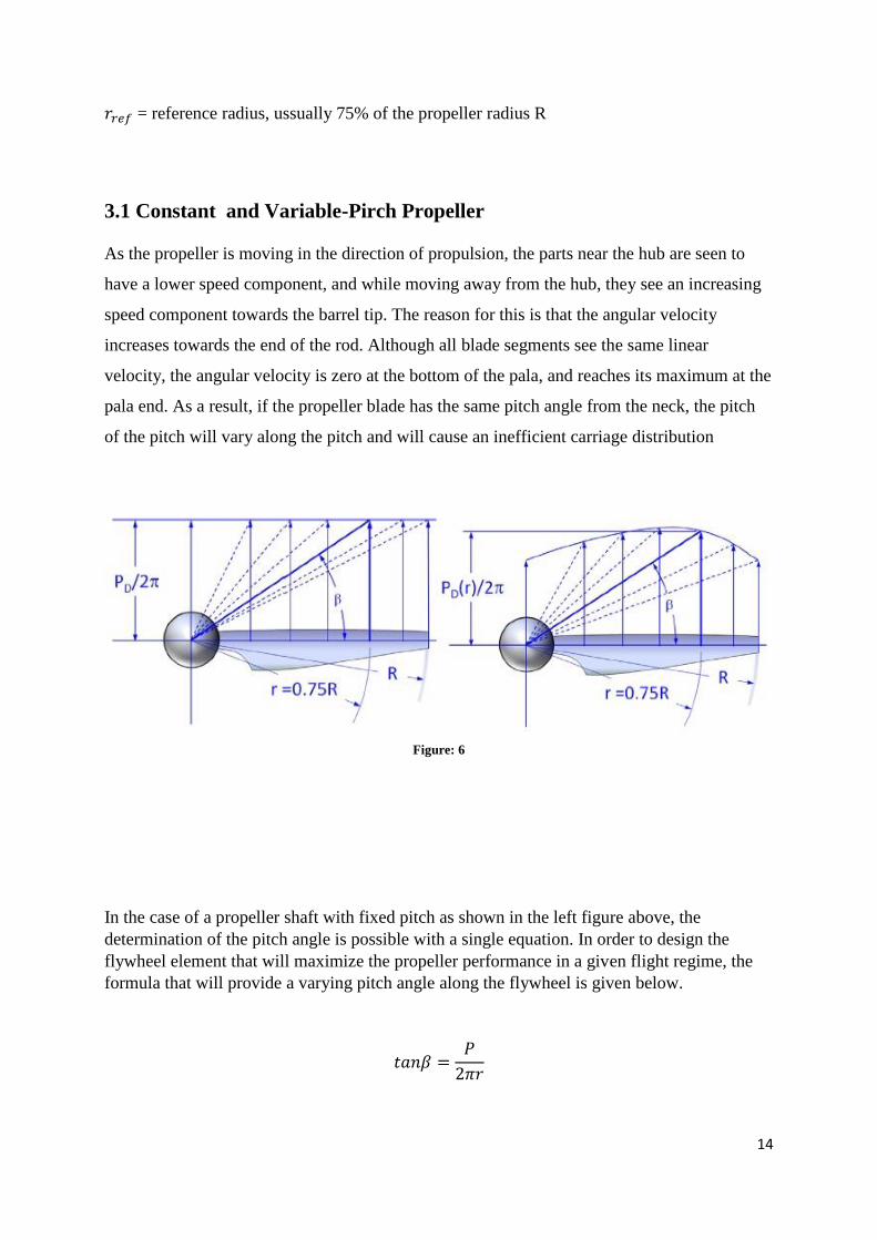
As the propeller is moving in the direction of propulsion, the parts near the hub are seen to
have a lower speed component, and while moving away from the hub, they see an increasing
speed component towards the barrel tip. The reason for this is that the angular velocity
increases towards the end of the rod. Although all blade segments see the same linear
velocity, the angular velocity is zero at the bottom of the pala, and reaches its maximum at the
pala end. As a result, if the propeller blade has the same pitch angle from the neck, the pitch
of the pitch will vary along the pitch and will cause an inefficient carriage distribution
In the case of a propeller shaft with fixed pitch as shown in the left figure above, the
determination of the pitch angle is possible with a single equation. In order to design the
flywheel element that will maximize the propeller performance in a given flight regime, the
formula that will provide a varying pitch angle along the flywheel is given below.
𝑡𝑎𝑛𝛽 =𝑃
2𝜋𝑟
Figure: 6
15
The equation presents a simple calculation of the pitch angle of any section of the propeller
blade with a constant P error. It is much more complicated to determine the pitch angle in
variable pitch pitches.
3.2 Fundamental Relationships of Propeller Rotation
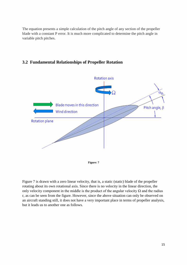
Figure 7 is drawn with a zero linear velocity, that is, a static (static) blade of the propeller
rotating about its own rotational axis. Since there is no velocity in the linear direction, the
only velocity component in the middle is the product of the angular velocity Ω and the radius
r, as can be seen from the figure. However, since the above situation can only be observed on
an aircraft standing still, it does not have a very important place in terms of propeller analysis,
but it leads us to another one as follows.
Figure: 7
16
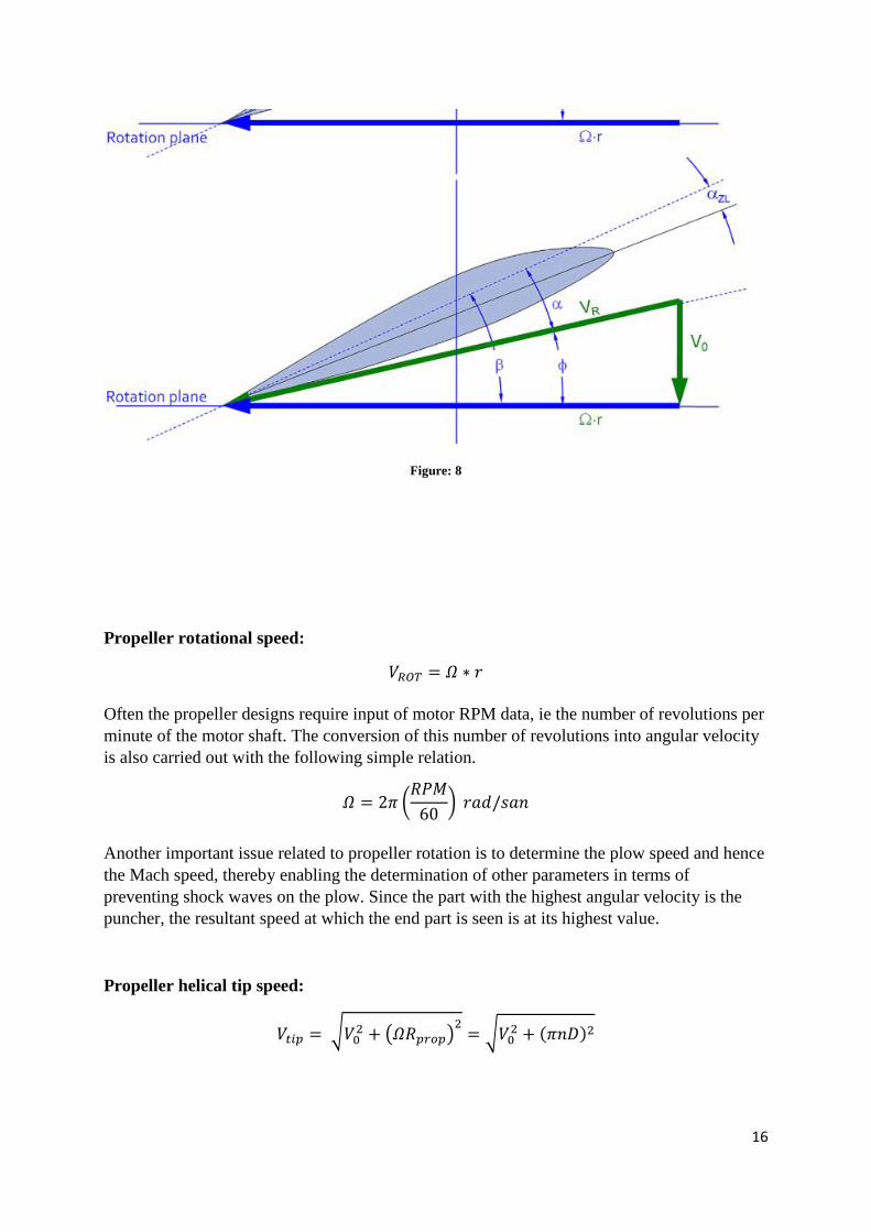
Propeller rotational speed:
𝑉𝑅𝑂𝑇 = 𝛺 ∗ 𝑟
Often the propeller designs require input of motor RPM data, ie the number of revolutions per
minute of the motor shaft. The conversion of this number of revolutions into angular velocity
is also carried out with the following simple relation.
𝛺 = 2𝜋 (𝑅𝑃𝑀
60) 𝑟𝑎𝑑/𝑠𝑎𝑛
Another important issue related to propeller rotation is to determine the plow speed and hence
the Mach speed, thereby enabling the determination of other parameters in terms of
preventing shock waves on the plow. Since the part with the highest angular velocity is the
puncher, the resultant speed at which the end part is seen is at its highest value.
Propeller helical tip speed:
𝑉𝑡𝑖𝑝 = √𝑉02 + (𝛺𝑅𝑝𝑟𝑜𝑝)
2= √𝑉0
2 + (𝜋𝑛𝐷)2
Figure: 8
17
𝑉𝑡𝑖𝑝 = √𝑉02 + (
𝜋𝑅𝑃𝑀𝐷
60)
2
Tip Mach number:
𝑀𝑡𝑖𝑝 =𝑉𝑡𝑖𝑝
𝑎0=
𝑉𝑡𝑖𝑝
√𝛾𝑅𝑇
It is useful to note that the flyer parts can also operate at supersonic speeds but cause very
high noise. That is why the propellers are often able to see towards the blade ends and have a
certain sweep angle. In addition to geometric design, other operations such as reducing the
diameter of the propeller, reducing the number of engine revolutions must also be taken into
consideration when the propeller blades can operate at subsonic speeds. Raising the speed of
the palawast to the supersonic speed also causes other major problems as well as high noise.
One of these problems is the reduction in propeller efficiency and the need for higher torque
values to rotate the propeller. Because the dragging force, which is increased by the formation
of the shock, gives priority to the need for higher torque, torque, which will compensate for
this dragging. So, in general, the blade tips are designed to work at subsonic speeds. And for
the sound velocity limit, a value of M = 0.6 for wooden propellers and a value of M = 0.75-
0.80 for pallets made of aluminum and composite products is taken into consideration. For
these reasons, it is necessary to make the necessary calculations in order to make the optimum
decision by comparing all the parameters carefully and comparing the levels of the positive
and negative effects of these parameters while designing the propeller.
4. Properties and selection of the propeller
In this section, some points to be considered when selecting propeller for any aircraft are
discussed.
additional and therefore the road map we need to take into account in our propeller project.
The following points therefore have to be taken into account and evaluated by the propeller
designer, and the interaction between the aircraft designer and the propeller designer also
sheds a certain amount of light.
• Prediction of propeller diameter
• Estimation of propeller pitch angle
• Targeted performance of the aircraft: take-off and climb performance requirements, targeted
cruising speed and altitude have a great effect on the propeller to be selected or designed.
• There is a great deal of importance in determining the propeller diameter and blade number
of engine features such as engine power (BHP), speed (RPM), and torque vibration.
• The higher the paddle speed, the better, but the end speed has a certain limit. Excessive
throttle velocities cause high noise and low fatigue due to shock waves.
18
• It is anticipated that the speed of the paddle for wooden propellers will be around M = 0.6.
• For metal and advanced composite propellers, it is expected that the barrel speed will be in
the range of M = 0.75-0.80.
• If the engine speed is too high, the gear reducer gear box must be used.
• High rotational speeds require fewer propeller blades or smaller blade areas.
• In engines with high power, when the number of revolutions starts to limit the magnitude of
the propeller diameter, the number of motors is increased to convert the motor power to
propulsion.
• Excessive large propeller diameter can cause high pitch speed and high noise, as well as the
distance between the ground and the shovel.
• Probes with more bars may have a lower diameter, but increasing the number of bars means
that the weight is also increasing.
Rapid Estimation of Required Prop Diameter
When choosing a propeller for any aircraft, it is important to determine the propeller diameter
at an early stage in an estimated speed because the calculation of the main parameters such as
engine speed, propeller strength, propeller speed is calculated over the propeller diameter. The
formula provided by Raymer is as follows:
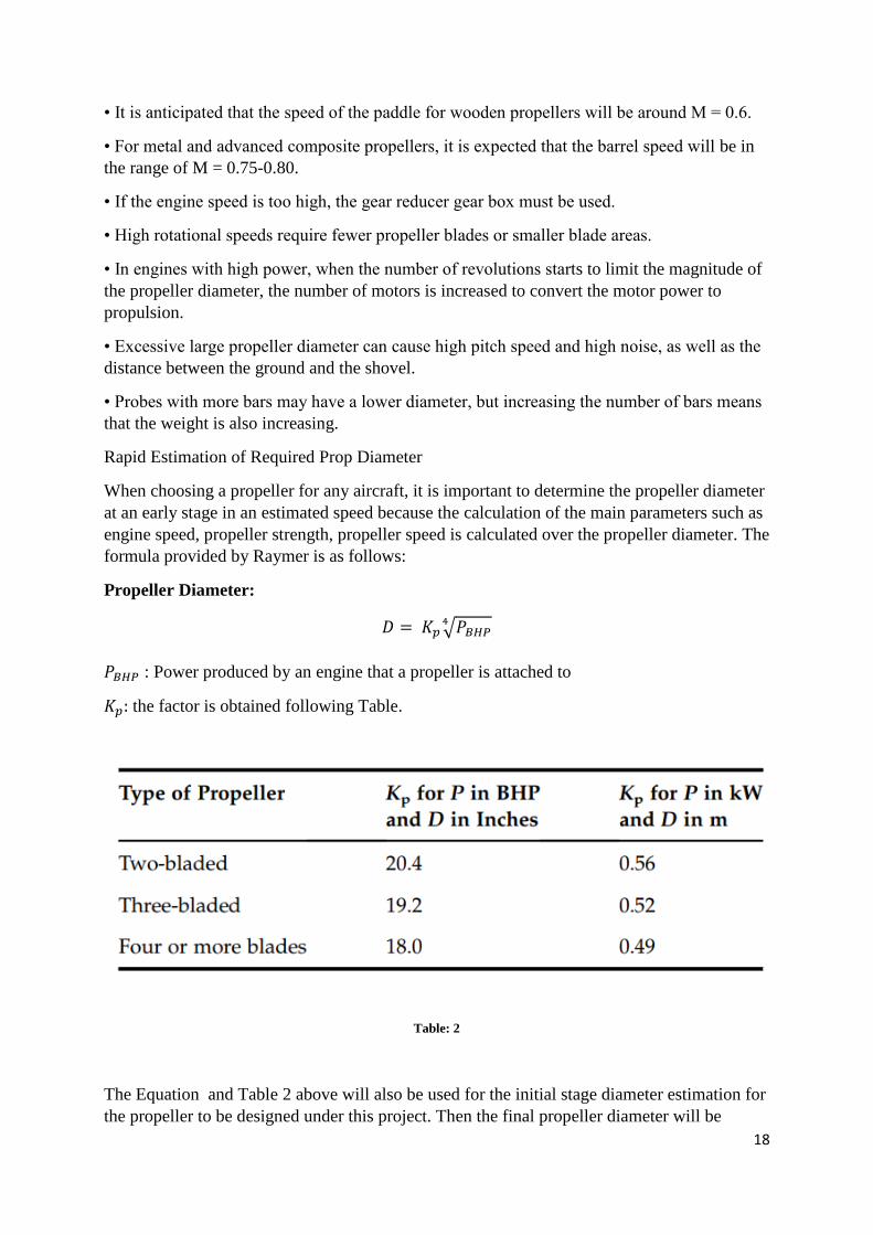
Propeller Diameter:
𝐷 = 𝐾𝑝 √𝑃𝐵𝐻𝑃4
𝑃𝐵𝐻𝑃 : Power produced by an engine that a propeller is attached to
𝐾𝑝: the factor is obtained following Table.
Table: 2
The Equation and Table 2 above will also be used for the initial stage diameter estimation for
the propeller to be designed under this project. Then the final propeller diameter will be
19
determined considering other parameters and will be used in the design and analysis phase. It
is useful to note that the above diameter determination formula is more based on statistical
data and gives an approximate idea for the propeller to be designed. However, in real life
propeller design projects, more professional methods are used to examine the designs tested in
the CFD and wind turbine environments and the propellers with much more efficient
geometry are designed and manufactured.
4.1 Advence ratio
Advence rate is an indication of how far a propeller has traveled per unit time in its unit time
and is expressed in the following formula.
𝐽 = 𝑉0
𝑛𝐷=
60𝑉0
𝑅𝑃𝑀 𝐷
4.2 Definition of Power adn Thrust –Related Coefficients
For the performance evaluation of the propeller, some unitless coefficients are needed. These
coefficients are independent of the units and can be used to measure and compare some of the
performance values displayed by the propeller. One of these coefficients is the power
coefficient and is expressed as follows.
Power coefficient:
𝐶𝑃 = 𝑃
𝜌𝑛3𝐷5=
𝑃
𝜌 (𝑅𝑃𝑀
60 )3
𝐷5
P: Power of engine, kW
𝜌 : density of fluid, kg/m3
D: propeller diameter
Thrust coefficient:
𝐶𝑇 = 𝑇
𝜌𝑛2𝐷4=
3600𝑇
𝜌𝑅𝑃𝑀2𝐷4
T: Thrust by produced propeller, N
Torque Coefficient:
𝐶𝑄 = 𝑄
𝜌𝑛2𝐷5=
3600𝑄
𝜌𝑅𝑃𝑀2𝐷5=
𝐶𝑃
2𝜋
Q: Torque that rotates blades of propeller N.m
20
Power-Torque relation:
𝐶𝑄 = 𝑄
𝜌𝑛2𝐷5=
𝐶𝑃
2𝜋=
𝑃 𝜌𝑛3𝐷5⁄
2𝜋 → 𝑃 = 2𝜋𝑛𝑄
4.3 Propeller Effiency
Not all of the power generated by a motor turns into propulsion, and it is obvious that a
certain amount of power will inevitably be lost due to losses in between. Generally, the losses
that occur when the propeller is operating are divided into viscous friction and inviscid losses.
But let's define the efficiency of the propeller in order to explain the loss of propeller losses in
the current phase. The propeller efficiency can be defined as the total motor-generated gentle
ratio of the portion of the motor power that is converted to propulsion power (impulse x free-
running speed). A typical maximum output value is around 0.8 and 0.9.
Propeller Effiency:
𝜂𝑝 = 𝑇𝑉
𝑃= 𝐽
𝐶𝑇
𝐶𝑃
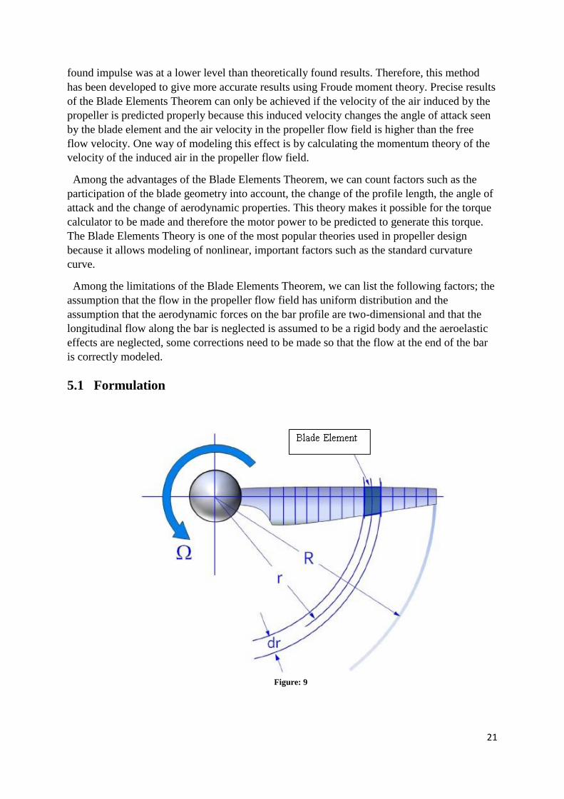
5. BLADE ELEMENT THEORY
The blade Elements Theory BET) is a method that tries to calculate the total thrust generated
by the propeller by dividing each palm into a certain number of blade elements. According to
this theory, each blade element is perceived as an independent two-dimensional wing profile,
and aerodynamic forces acting on this profile are calculated according to local flow
properties. After the aerodynamic forces on each cross section have been calculated, all of
these forces are gathered from the bottom of the blade to the tip of the blade to find the total
thrust force and total torque that the propeller has generated. Propellers are usually thicker at
the bottom of the blade, while at the tip of the blade they have thinner blade profiles. The
Blade Elements Theory has the capacity to account for such changes, but these differences
must also be taken into account when analyzing. One of the most important features of the
Blade Elements Theory is that it takes account of the original blade geometry, that is to say
the pitch angle, the sweep angles, the profile thicknesses and the profile shapes of the blade
element for each impeller.
The Blade Elements Theory was first introduced by the Polish scientist Stefan Drzewiecki
(1844-1938) and was introduced to the scientific world in 1920 as the theory of the basic
elements of the Helicopter General Theory. However, because this simplified theory does not
account for the induced velocity component in the propeller flow field, the experimentally
21
Figure: 9
found impulse was at a lower level than theoretically found results. Therefore, this method
has been developed to give more accurate results using Froude moment theory. Precise results
of the Blade Elements Theorem can only be achieved if the velocity of the air induced by the
propeller is predicted properly because this induced velocity changes the angle of attack seen
by the blade element and the air velocity in the propeller flow field is higher than the free
flow velocity. One way of modeling this effect is by calculating the momentum theory of the
velocity of the induced air in the propeller flow field.
Among the advantages of the Blade Elements Theorem, we can count factors such as the
participation of the blade geometry into account, the change of the profile length, the angle of
attack and the change of aerodynamic properties. This theory makes it possible for the torque
calculator to be made and therefore the motor power to be predicted to generate this torque.
The Blade Elements Theory is one of the most popular theories used in propeller design
because it allows modeling of nonlinear, important factors such as the standard curvature
curve.
Among the limitations of the Blade Elements Theorem, we can list the following factors; the
assumption that the flow in the propeller flow field has uniform distribution and the
assumption that the aerodynamic forces on the bar profile are two-dimensional and that the
longitudinal flow along the bar is neglected is assumed to be a rigid body and the aeroelastic
effects are neglected, some corrections need to be made so that the flow at the end of the bar
is correctly modeled.
5.1 Formulation
22
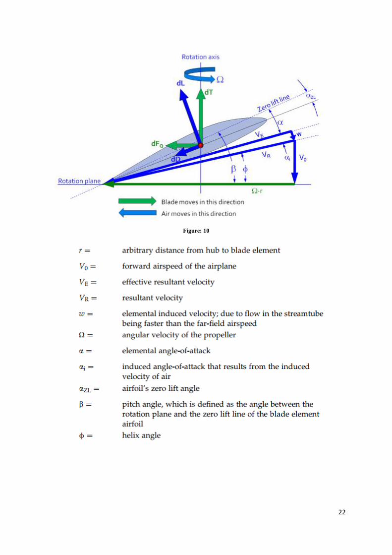
Figure: 10
23
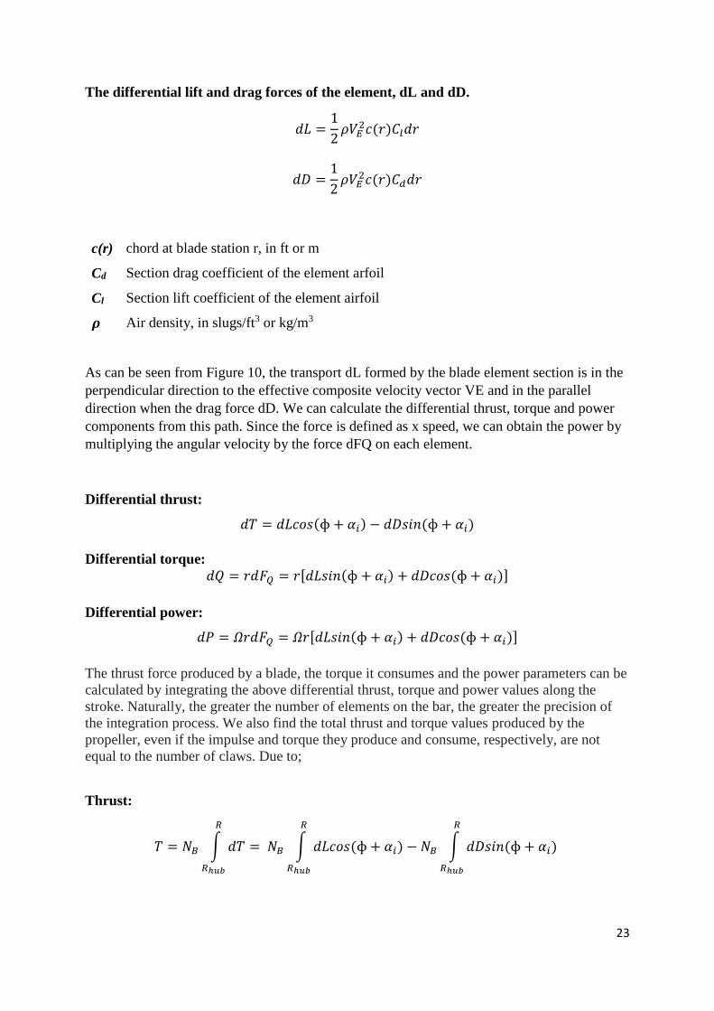
The differential lift and drag forces of the element, dL and dD.
𝑑𝐿 =1
2𝜌𝑉𝐸
2𝑐(𝑟)𝐶𝑙𝑑𝑟
𝑑𝐷 =1
2𝜌𝑉𝐸
2𝑐(𝑟)𝐶𝑑𝑑𝑟
c(r) chord at blade station r, in ft or m
Cd Section drag coefficient of the element arfoil
Cl Section lift coefficient of the element airfoil
𝝆 Air density, in slugs/ft3 or kg/m3
As can be seen from Figure 10, the transport dL formed by the blade element section is in the
perpendicular direction to the effective composite velocity vector VE and in the parallel
direction when the drag force dD. We can calculate the differential thrust, torque and power
components from this path. Since the force is defined as x speed, we can obtain the power by
multiplying the angular velocity by the force dFQ on each element.
Differential thrust:
𝑑𝑇 = 𝑑𝐿𝑐𝑜𝑠(ɸ + 𝛼𝑖) − 𝑑𝐷𝑠𝑖𝑛(ɸ + 𝛼𝑖)
Differential torque:
𝑑𝑄 = 𝑟𝑑𝐹𝑄 = 𝑟[𝑑𝐿𝑠𝑖𝑛(ɸ + 𝛼𝑖) + 𝑑𝐷𝑐𝑜𝑠(ɸ + 𝛼𝑖)]
Differential power:
𝑑𝑃 = 𝛺𝑟𝑑𝐹𝑄 = 𝛺𝑟[𝑑𝐿𝑠𝑖𝑛(ɸ + 𝛼𝑖) + 𝑑𝐷𝑐𝑜𝑠(ɸ + 𝛼𝑖)]
The thrust force produced by a blade, the torque it consumes and the power parameters can be
calculated by integrating the above differential thrust, torque and power values along the
stroke. Naturally, the greater the number of elements on the bar, the greater the precision of
the integration process. We also find the total thrust and torque values produced by the
propeller, even if the impulse and torque they produce and consume, respectively, are not
equal to the number of claws. Due to;
Thrust:
𝑇 = 𝑁𝐵 ∫ 𝑑𝑇
𝑅
𝑅ℎ𝑢𝑏
= 𝑁𝐵 ∫ 𝑑𝐿𝑐𝑜𝑠(ɸ + 𝛼𝑖)
𝑅
𝑅ℎ𝑢𝑏
− 𝑁𝐵 ∫ 𝑑𝐷𝑠𝑖𝑛(ɸ + 𝛼𝑖)
𝑅
𝑅ℎ𝑢𝑏
24
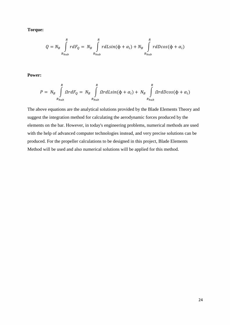
Torque:
𝑄 = 𝑁𝐵 ∫ 𝑟𝑑𝐹𝑄
𝑅
𝑅ℎ𝑢𝑏
= 𝑁𝐵 ∫ 𝑟𝑑𝐿𝑠𝑖𝑛(ɸ + 𝛼𝑖)
𝑅
𝑅ℎ𝑢𝑏
+ 𝑁𝐵 ∫ 𝑟𝑑𝐷𝑐𝑜𝑠(ɸ + 𝛼𝑖)
𝑅
𝑅ℎ𝑢𝑏
Power:
𝑃 = 𝑁𝐵 ∫ 𝛺𝑟𝑑𝐹𝑄
𝑅
𝑅ℎ𝑢𝑏
= 𝑁𝐵 ∫ 𝛺𝑟𝑑𝐿𝑠𝑖𝑛(ɸ + 𝛼𝑖)
𝑅
𝑅ℎ𝑢𝑏
+ 𝑁𝐵 ∫ 𝛺𝑟𝑑𝐷𝑐𝑜𝑠(ɸ + 𝛼𝑖)
𝑅
𝑅ℎ𝑢𝑏
The above equations are the analytical solutions provided by the Blade Elements Theory and
suggest the integration method for calculating the aerodynamic forces produced by the
elements on the bar. However, in today's engineering problems, numerical methods are used
with the help of advanced computer technologies instead, and very precise solutions can be
produced. For the propeller calculations to be designed in this project, Blade Elements
Method will be used and also numerical solutions will be applied for this method.
25
REFERENCES
Gudmundsson, S. (2014). General Aviation Aircraft Design: Applied Methods and
Procedures, The Anatomy of the Propeller, 583-619.
Raymer, D.P. (2012). Aircraft Design A Conceptual Approach, Propulsion, 327-351.