Embed Size (px)
Citation preview
ISSUES WITH PERMANENT MAGNETS
M. Kumada, NIRS, Chiba, JapanY. Iwashita, Kyoto University, Kyoto, Japan
E.A. Antokhin, Budker institute for Nuclear Physics, Novosibirsk, Russia
AbstractVarious issues of a linear collider final focus system
using permanent magnet quadrupole were discussed;temperature stability, radiation damage, incorporation of avacuum system, variability of field strength, interactionwith solenoid and finally an effort of stronger final focusmagnet. Some of the issues may be solved and others arestill open questions.
Details of variability of the permanent magnet and anew idea of temperature stabilization are presented bycoauthors as separate papers.
1 TEMPERATURE STABILITY
Using NdFeB magnet is advantageous over SmComagnet in strength and cost but disadvantageous intemperature stability and radiation hardness. Typicaltemperature coefficient of naked NdFeB is 0.11 % /degreeCelsius. This stability of a raw material may beacceptable in an application of wiggler or undulator but0.1 % variation is out of question in an application of thelinear collider final focus quadrupole magnets.
Stabilization of the permanent magnet is possible byseveral methods, namely passive compensation and activecompensation of the temperature variation of magneticmaterial.
Thermal insulation method is one of the passivecompensation. Main contribution of a temperature changeof a magnet comes from an ambient temperature of a timescale of a period of day. In case of an air conditionedenvironment, this temperature variation also come intoeffect. Thermal insulation greatly helps stabilizationespecially for a magnet of large heat capacity.
Variation of amplitude of the magnet material isconsiderably reduced by lowering a heat conduction tothe material. This insulation technique is essential inMagnet Resonance Imaging(MRI) magnet.
Other clever method is to combine a permanent magnetmaterial with different temperature coefficient. Foster etal. of Fermilab developed a method of using backupmaterial of positive temperature coefficient to apermanent magnet material of negative temperaturecoefficient in a 8 GeV antiproton storage ring made ofFerrite permanent magnet. They had a successful result inpassive temperature compensation.
One of our coauthors, E.A. Antokhin, proposed apassive compensation of different approach. He proposesto combine two permanent magnet of differenttemperature coefficient of the same sign, namely, SmCoand NdFeB. In this case, direction of magnetization of the
compensator is opposite of that of the main magnet.Detail is described in a separate paper by him.
Both compensation above is categorized as a transversecompensation.
Y.Iwashita proposed a pair of magnet with differenttemperature coefficient of Focusing Quadrupole andDefocusing Quadrupole. In this case, one of thecompensation magnet is made very thin. This is the caseof a longitudinal compensation.
In either case of a scheme of using backup material, welose an efficiency of magnet volume which is a tradeoffbetween stability and field strength.
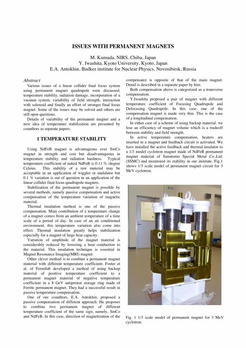
In active temperature compensation, heaters areinserted in a magnet and feedback circuit is activated. Wehave installed the active feedback and thermal insulator toa 1/3 model cyclotron magnet made of NdFeB permanentmagnet material of Sumitomo Special Metal Co.,Ltd.(SSMC) and monitored its stability in our institute. Fig.1shows 1/3 scale model of permanent magnet circuit for 3MeV cyclotron.
Fig. 1 1/3 scale model of permanent magnet for 3 MeVcyclotron.
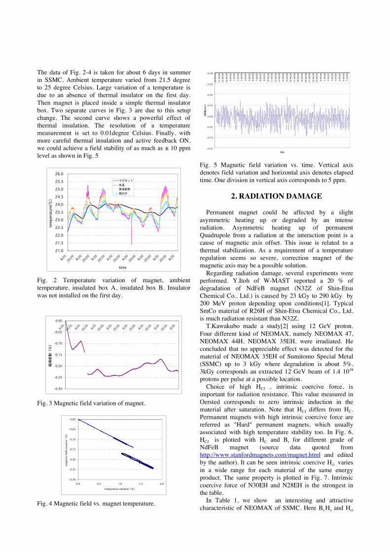
The data of Fig. 2-4 is taken for about 6 days in summerin SSMC. Ambient temperature varied from 21.5 degreeto 25 degree Celsius. Large variation of a temperature isdue to an absence of thermal insulator on the first day.Then magnet is placed inside a simple thermal insulatorbox. Two separate curves in Fig. 3 are due to this setupchange. The second curve shows a powerful effect ofthermal insulation. The resolution of a temperaturemeasurement is set to 0.01degree Celsius. Finally, withmore careful thermal insulation and active feedback ON,we could achieve a field stability of as much as ± 10 ppmlevel as shown in Fig. 5
21.0
21.5
22.0
22.5
23.0
23.5
24.0
24.5
25.0
25.5
26.0
8:20
20:208:20
20:208:20
20:208:20
20:208:20
20:208:20
20:208:20
20:208:20
time
temperature(℃)
マグネット
気温
簡易断熱
箱の中
Fig. 2 Temperature variation of magnet, ambienttemperature, insulated box A, insulated box B. Insulatorwas not installed on the first day.
-0.30
-0.25
-0.20
-0.15
-0.10
-0.05
0.00
8:20
20:208:20
20:208:20
20:208:20
20:208:20
20:208:20
20:208:20
20:208:20
磁場変動(%)
Fig. 3 Magnetic field variation of magnet.
-0.30
-0.25
-0.20
-0.15
-0.10
-0.05
0.00
0.0 0.5 1.0 1.5 2.0
temperature variation(℃)
magnetic field variation(%)
Fig. 4 Magnetic field vs. magnet temperature.
-6175
-6170
-6165
-6160
-6155
-6150
-6145
-6140
20:40:00
21:40:00
22:40:00
23:40:00
0:40:00
1:40:00
2:40:00
3:40:00
4:40:00
5:40:00
6:40:00
7:40:00
8:40:00
9:40:00
10:40:00
11:40:00
12:40:00
13:40:00
14:40:00
15:40:00
16:40:00
17:40:00
18:40:00
19:40:00
20:40:00
21:40:00
22:40:00
23:40:00
0:40:00
1:40:00
2:40:00
3:40:00
4:40:00
5:40:00
6:40:00
7:40:00
時刻
変動量(ppm)
Fig. 5 Magnetic field variation vs. time. Vertical axisdenotes field variation and horizontal axis denotes elapsedtime. One division in vertical axis corresponds to 5 ppm.
2. RADIATION DAMAGE
Permanent magnet could be affected by a slightasymmetric heating up or degraded by an intenseradiation. Asymmetric heating up of permanentQuadrupole from a radiation at the interaction point is acause of magnetic axis offset. This issue is related to athermal stabilization. As a requirement of a temperatureregulation seems so severe, correction magnet of themagnetic axis may be a possible solution.
Regarding radiation damage, several experiments wereperformed. Y.Itoh of W-MAST reported a 20 % ofdegradation of NdFeB magnet (N32Z of Shin-EtsuChemical Co., Ltd.) is caused by 23 kGy to 290 kGy by200 MeV proton depending upon conditions[1]. TypicalSmCo material of R26H of Shin-Etsu Chemical Co., Ltd.is much radiation resistant than N32Z.
T.Kawakubo made a study[2] using 12 GeV proton.Four different kind of NEOMAX, namely NEOMAX 47,NEOMAX 44H, NEOMAX 35EH, were irradiated. Heconcluded that no appreciable effect was detected for thematerial of NEOMAX 35EH of Sumitomo Special Metal(SSMC) up to 3 kGy where degradation is about 5%.3kGy corresponds an extracted 12 GeV beam of 1.4 1018
protons per pulse at a possible location.Choice of high HCJ , intrinsic coercive force, is
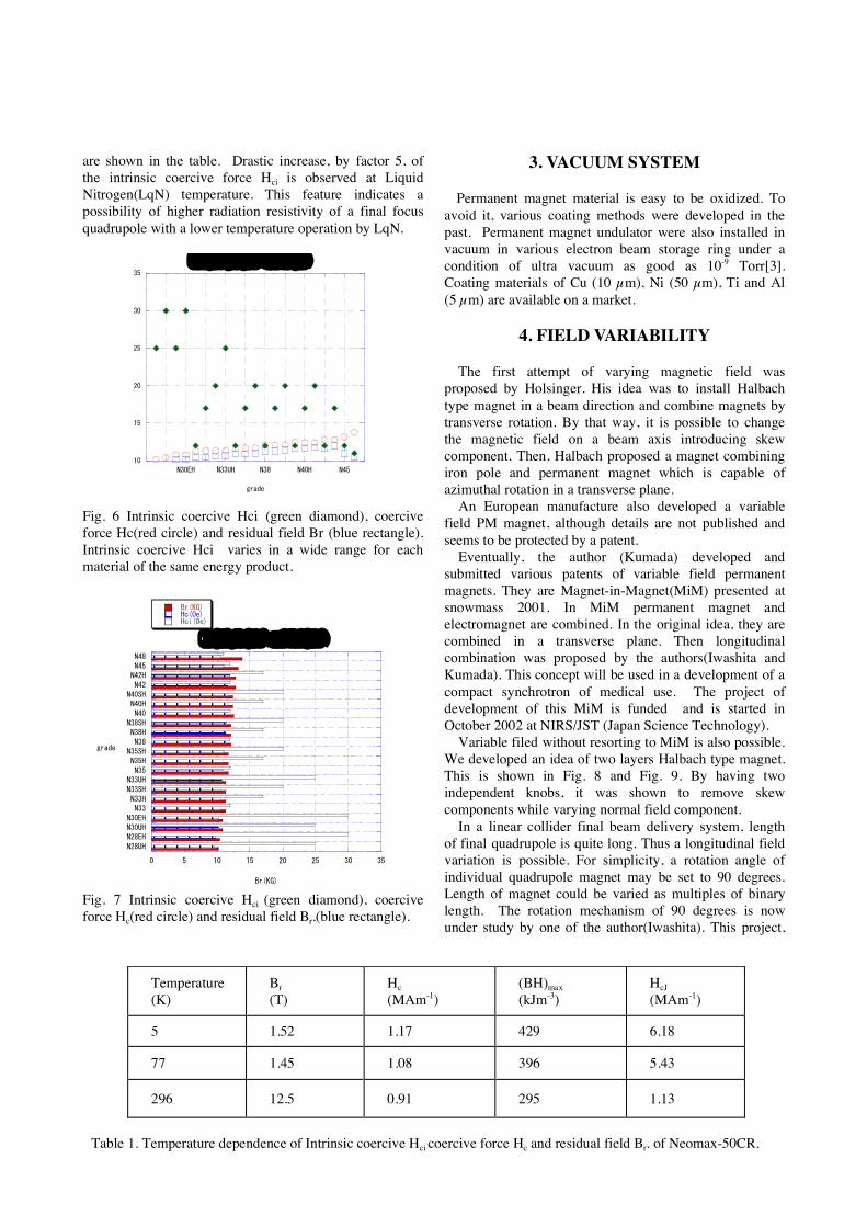
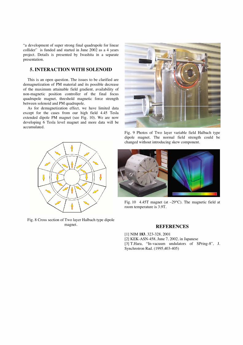
important for radiation resistance. This value measured inOersted corresponds to zero intrinsic induction in thematerial after saturation. Note that HCJ differs from HC.Permanent magnets with high intrinsic coercive force arereferred as "Hard" permanent magnets, which usuallyassociated with high temperature stability too. In Fig. 6,HCJ is plotted with HC and Br for different grade ofNdFeB magnet (source data quoted fromhttp://www.stanfordmagnets.com/magnet.html and editedby the author). It can be seen intrinsic coercive Hci variesin a wide range for each material of the same energyproduct. The same property is plotted in Fig. 7. Intrinsiccoercive force of N30EH and N28EH is the strongest inthe table.
In Table 1, we show an interesting and attractivecharacteristic of NEOMAX of SSMC. Here Br,Hc and Hci
are shown in the table. Drastic increase, by factor 5, ofthe intrinsic coercive force Hci is observed at LiquidNitrogen(LqN) temperature. This feature indicates apossibility of higher radiation resistivity of a final focusquadrupole with a lower temperature operation by LqN.
10
15
20
25
30
35
N30EH N33UH N38 N40H N45
Hci(kOe),Hc(kOe) and Br(kG)
grade
Fig. 6 Intrinsic coercive Hci (green diamond), coerciveforce Hc(red circle) and residual field Br (blue rectangle).Intrinsic coercive Hci varies in a wide range for eachmaterial of the same energy product.
0 5 10 15 20 25 30 35
N28UH
N28EHN30UHN30EH
N33N33HN33SH
N33UHN35
N35HN35SHN38
N38HN38SH
N40N40HN40SH
N42N42HN45
N48
Br(kG),Hc(kOe) and Hci(kOe)
Br(KG)Hc(Oe)Hci(Oe)
Br(KG)
grade
Fig. 7 Intrinsic coercive Hci (green diamond), coerciveforce Hc(red circle) and residual field Br.(blue rectangle).
3. VACUUM SYSTEM
Permanent magnet material is easy to be oxidized. Toavoid it, various coating methods were developed in thepast. Permanent magnet undulator were also installed invacuum in various electron beam storage ring under acondition of ultra vacuum as good as 10-9 Torr[3].Coating materials of Cu (10 µm), Ni (50 µm), Ti and Al(5 µm) are available on a market.
4. FIELD VARIABILITY
The first attempt of varying magnetic field wasproposed by Holsinger. His idea was to install Halbachtype magnet in a beam direction and combine magnets bytransverse rotation. By that way, it is possible to changethe magnetic field on a beam axis introducing skewcomponent. Then, Halbach proposed a magnet combiningiron pole and permanent magnet which is capable ofazimuthal rotation in a transverse plane.
An European manufacture also developed a variablefield PM magnet, although details are not published andseems to be protected by a patent.
Eventually, the author (Kumada) developed andsubmitted various patents of variable field permanentmagnets. They are Magnet-in-Magnet(MiM) presented atsnowmass 2001. In MiM permanent magnet andelectromagnet are combined. In the original idea, they arecombined in a transverse plane. Then longitudinalcombination was proposed by the authors(Iwashita andKumada). This concept will be used in a development of acompact synchrotron of medical use. The project ofdevelopment of this MiM is funded and is started inOctober 2002 at NIRS/JST (Japan Science Technology).
Variable filed without resorting to MiM is also possible.We developed an idea of two layers Halbach type magnet.This is shown in Fig. 8 and Fig. 9. By having twoindependent knobs, it was shown to remove skewcomponents while varying normal field component.
In a linear collider final beam delivery system, lengthof final quadrupole is quite long. Thus a longitudinal fieldvariation is possible. For simplicity, a rotation angle ofindividual quadrupole magnet may be set to 90 degrees.Length of magnet could be varied as multiples of binarylength. The rotation mechanism of 90 degrees is nowunder study by one of the author(Iwashita). This project,
Temperature(K)(
Br(T)
Hc(MAm-1)
(BH)max(kJm-3)
HcJ(MAm-1)
5 1.52 1.17 429 6.18
77 1.45 1.08 396 5.43
296 12.5 0.91 295 1.13
Table 1. Temperature dependence of Intrinsic coercive Hci coercive force Hc and residual field Br. of Neomax-50CR.
“a development of super strong final quadrupole for linearcollider” is funded and started in June 2002 as a 4 yearsproject. Details is presented by Iwashita in a separatepresentation.
5. INTERACTION WITH SOLENOID
This is an open question. The issues to be clarified aredemagnetization of PM material and its possible decreaseof the maximum attainable field gradient, availability ofnon-magnetic position controller of the final focusquadrupole magnet, threshold magnetic force strengthbetween solenoid and PM quadrupole.
As for demagnetization effect, we have limited dataexcept for the cases from our high field 4.45 Teslaextended dipole PM magnet (see Fig. 10). We are nowdeveloping 6 Tesla level magnet and more data will beaccumulated.
Fig. 8 Cross section of Two layer Halbach type dipolemagnet.
Fig. 9 Photos of Two layer variable field Halbach typedipole magnet. The normal field strength could bechanged without introducing skew component.
Fig. 10 4.45T magnet (at –29°C). The magnetic field atroom temperature is 3.9T.
REFERENCES[1] NIM 183, 323-328, 2001[2] KEK-ASN-458, June 7, 2002, in Japanese[3] T.Hara, “In-vacuum undulators of SPring-8”, J.Synchrotron Rad. (1995,403-405)


![Permanent magnets Ferrite, ndFeB, alniCo & smCo … · NdFeB BLS Magnet [6] Permanent magnets BLS Magnet [7] Permanent magnets nDFeB magnets Grade Remanence Remanence Coercive force](https://img.pdfslide.us/doc/110x75/5b915de509d3f210288b8282/permanent-magnets-ferrite-ndfeb-alnico-smco-ndfeb-bls-magnet-6-permanent.jpg)
![Grain-size dependent demagnetizing factors in permanent magnets · 2016-03-29 · 2Fe 14B magnets.[5] With the same reason-ing the size dependence of the coercive eld was modelled](https://img.pdfslide.us/doc/110x75/5f8f9d038ba56e0dde2594e5/grain-size-dependent-demagnetizing-factors-in-permanent-magnets-2016-03-29-2fe.jpg)