Embed Size (px)
Citation preview
May, 1999
NASA/CR-1999-000000
ISSUES IN THE PHYSICALINTEGRATION OF TERMINAL AREAPRODUCTIVITY (TAP) SYSTEM ANDDISPLAYS INTO COMMERCIALAIRCRAFT
John Cotton,John Cotton and Associates
Walter A. Johnson,Rockwell Collins Flight Dynamics
Martin F.J. Schwirzke, Robert T. HennessyMonterey Technologies, Inc.
i
ACKNOWLEDGEMENTS
This work was performed by Monterey Technologies, Inc under NASA Contract No. NAS2-
14113, Deliver Order No. 35.
The authors are grateful for the direction and support of Dr. David Foyle of the Flight
Management and Human Factors Division at NASA Ames Research Center.
The authors extend their thanks to the management of Alaska Airlines, Cathay Pacific Airways,
and Skywest for making the aircraft available for this study and to the personnel of the same
organizations who assistance in this work was much appreciated.
ii
TABLE OF CONTENTS
ACKNOWLEDGEMENTS .......................................................................................................i
LIST OF ACRONYMS.............................................................................................................v
EXECUTIVE SUMMARY.......................................................................................................1
OBJECTIVES OF THE PHYSICAL COMPATIBILITY ANALYSIS................................................................... 1
AIRCRAFT EXAMINED................................................................................................................... 1
CONCLUSIONS AND RECOMMENDATIONS......................................................................................... 2
INTRODUCTION ....................................................................................................................4
PHYSICAL AND PROCEDURAL COMPATIBILITY OF TAP SYSTEM .........................4
METHOD..................................................................................................................................5
INVESTIGATION TEAM.................................................................................................................. 5
OVERVIEW OF TECHNICAL APPROACH ............................................................................................. 5
CHARACTERISTICS OF THE TAP TECHNOLOGIES................................................................................ 6
Center TRACON Automation System /Flight Management System (CTAS/FMS) ................................. 6Airborne Information for Lateral Spacing (AILS) ......................................................................... 7Roll Out and Turn Off (ROTO) ................................................................................................. 8Taxiway — Navigation and Situation Awareness (T-NASA)............................................................. 8
SELECTION OF AIRCRAFT FOR EXAMINATION.................................................................................. 10
Population of US Air Carrier Aircraft...................................................................................... 10Choice of Aircraft ................................................................................................................. 11
EMB-120.......................................................................................................................................................................................12
MD-80 SERIES.............................................................................................................................................................................12
Boeing B737-300/400/500 .....................................................................................................................................................13
B747-400, B757, B767, B777, MD-11 .................................................................................................................................13
B747-100/200/300, L-1011, DC-10 30/40 .........................................................................................................................13
AIRCRAFT ITEMS TO BE EXAMINED FOR TAP SYSTEM COMPATIBILITY................................................. 13
SCOPE OF AIRCRAFT EXAMINATIONS FOR TAP SYSTEM COMPATIBILITY .............................................. 14
AIRCRAFT EXAMINATIONS .......................................................................................................... 15
EMB-120 (Skywest configuration ) ......................................................................................... 16MD-87 (Alaska Airlines configuration) ................................................................................... 16B737-400 (Alaska Airlines configuration)................................................................................ 17B747-400 (Cathay Pacific Airways configuration) .................................................................... 17B747-200(F) (Cathay Pacific Airways configuration) ................................................................ 17
Analysis of Results and Implications for TAP Systems Retrofitting .....................................18
RETROFITTING OF ALL TYPES OF AIRCRAFT IS POTENTIALLY FEASIBLE ................................................ 22
TAP RETROFITTING ISSUES......................................................................................................... 22
HUD................................................................................................................................... 22Panel Mounted Display.......................................................................................................... 22TAP Avionics ....................................................................................................................... 23
ALTERNATIVE TO INDIVIDUAL RETROFITTING BY AIRCRAFT TYPE...................................................... 23
TAP INSTALLATION CONSIDERATIONS........................................................................................... 24
Development of the Tap Common Processor and Display............................................................. 27Tap Processor Display Manufacturing and Installation Issues ...................................................... 29
HUD INTERFACE ISSUES.............................................................................................................. 30
Airworthiness Certification and Operational Approval ..........................................................30
AIRWORTHINESS CERTIFICATION.................................................................................................. 31
OPERATIONAL CERTIFICATION..................................................................................................... 32
iii
CERTIFICATION LESSONS LEARNED APPLIED TO TAP ....................................................................... 32
Certification Planning........................................................................................................... 32Transfer of Certified Data...................................................................................................... 32Manufacturer s Internal Work can Shorten Certification Process................................................... 33Choose Experts Wisely ........................................................................................................... 33Concerted Effort will be Required to Facilitate Acceptance of TAP................................................ 33TAP Training Development Should be Part of TAP Program........................................................ 33
Projected Costs for Aircraft TAP Improvement Installations.................................................33
SYSTEM DEVELOPMENT.............................................................................................................. 34
PRODUCTION EQUIPMENT COSTS.................................................................................................. 34
STC INSTALLATION AND CERTIFICATION COSTS............................................................................. 35
INSTALLATION AND CERTIFICATION COSTS FOR SUBSEQUENT TYPES OF AIRCRAFT................................. 36
INSTALLATION AND CERTIFICATION COSTS FOR SUBSEQUENT AIRCRAFT OF THE SAME TYPE ................... 36
SUMMARY OF COSTS.................................................................................................................. 36
Influences on the Entry of TAP System into U.S. Air Carrier Fleets .....................................41
ECONOMIC BENEFITS ................................................................................................................. 41
TECHNICAL PERFORMANCE ......................................................................................................... 41
MARKETING PUSH..................................................................................................................... 41
REGULATORY MANDATE............................................................................................................ 44
TAP SYSTEM OFFERED AS AN OEM ITEM ...................................................................................... 44
RETROFIT MARKET WILL PREDOMINATE OVER OEM MARKET.......................................................... 44
TECHNICAL FACILITATION.......................................................................................................... 44
CONCLUSIONS......................................................................................................................46
RECOMMENDATIONS........................................................................................................48
TECHNICAL.............................................................................................................................. 48
PROGRAMMATIC ....................................................................................................................... 48
REFERENCES.........................................................................................................................50
APPENDIX A - DESCRIPTIONS OF TAP SYSTEM TECHNOLOGIES..........................51
APPENDIX B - SELECTED COCKPIT PHOTOS OF THE EMB-120 AIRCRAFT
(SKYWEST CONFIGURATION)..........................................................................................66
APPENDIX C - SELECTED COCKPIT PHOTOS OF THE MD-87 AIRCRAFT
(ALASKA AIRLINES CONFIGURATION).........................................................................70
APPENDIX D - SELECTED COCKPIT PHOTOS OF THE B737-400 AIRCRAFT
(ALASKA AIRLINES CONFIGURATION).........................................................................74
APPENDIX E - SELECTED COCKPIT PHOTOS OF THE B747-400 AIRCRAFT
(CATHAY PACIFIC CONFIGURATION) ..........................................................................78
APPENDIX F - SELECTED COCKPIT PHOTOS OF THE B747-200(F) AIRCRAFT
(CATHAY PACIFIC AIRWAYS FREIGHTER CONFIGURATION)................................82
iv
LIST OF FIGURESFigure 1. CTAS/FMS Integration..............................................................................................6
Figure 2. Primary Flight Display (with AILS Resolution Advisory, left), AILS Navigation
Display enhancements, right).............................................................................................7
Figure 3. ROTO Airborne Symbology (left) and Ground Symbology (right). .........................8
Figure 4. Taxi Map Perspective Mode (left) and Overhead Mode (right)................................9
Figure 5. T-NASA Taxi HUD and T-NASA Taxi HUD Hold Short graphics..........................9
Figure 6. Schematic of architecture of common TAP processor and displays........................25
Figure 7. Factors Influencing entry of TAP system in air carrier fleets..................................43
LIST OF TABLESTable 1. Number of Air Carriers and Aircraft by Type of Operation at FAA Controlled
Airports............................................................................................................................10
Table 2. Aircraft Types, Models, EFIS Characteristics and Number in Fleet........................11
Table 3. Aircraft Checklist for TAP Systems Compatibility.................................................15
Table 4. Aircraft Models Inspected, Operators, and Inspection Location.............................15
Table 5. Summary of Aircraft Characteristics Relevant to TAP Retrofit Sheet 1 of 2............19
Table 6 TAP Retrofit Issues by Aircraft Type.......................................................................21
Table 7. Estimates of Elements of Cost for Retrofitting TAP System....................................39
Table 8. Example of Costing Method for 200 Aircraft of 2 Types for First TAP Carrier......40
Table 9. Number of Aircraft, and Percent with EFIS, by Size and Year..................................45
Table 10. Current Members of the Airlines Electronic Engineering Committee......................46
v
LIST OF ACRONYMSACO Aircraft Certification Office
ADI Attitude Director Indicator
ADS-B Automatic Dependent System - Broadcast
AEEC Airlines Electronic Engineering Committee
AHRS Attitude and Heading Reference System
AILS Airborne Information for Lateral Spacing
AIM Aeronautical Information Manual
AMC Airlines Maintenance Committee
ARINC Aeronautical Radio, Incorporated
ATA Air Transport Association
ATC Air Traffic Control
ATM Air Traffic Management
CAT III Category III
CAT 3A Category 3A
CDU Control Display Unit
COTS Commercial Off-the-Shelf
CPDLC Controller - Pilot Data Link Communications
CRM Crew Resource Management
CSPA Closely Spaced Parallel Approaches
CTAS Center TRACON Automation System
DA Descent Advisor
DAR Designated Airworthiness Representatives
DER Designated Engineering Representatives
EADI Electronic Attitude Director Indicator
EAEC European Airlines Electronics (Engineering) Committee
EDU Electronic Display Unit
EFIS Electronic Flight Instrument System
EHSI Electronic Horizontal Situation Indicator
EICAS Engine Indicating and Crew Alerting System
EGPWS Enhanced Ground Position Warning System
EMI Electro-Magnetic Interference
EMM Electronic Moving Map
EVS Enhanced Vision System
FAA Federal Aviation Administration
FAR Federal Aviation Regulations
FAST Final Approach Spacing Tool
FO First Officer
FMS Flight Management System
GA General Aviation
GC Ground Control
GCAW Ground Collision and Warning System
GPS Global Positioning System
GPWS Ground Proximity Warning System
HGS Head-Up Guidance System
HIRF High Intensity Radio Frequency (Interference)
HSI Horizontal Situation Indicator
HUD Head Up Display
vi
I/O Input/Output
IATA International Air Transport Association
ICAO International Civil Aviation Organization
ILS Instrument Landing System
IRS Inertial Reference System
IMC Instrument Meteorological Conditions
JAL Japan Air Lines
LCD Liquid Crystal Display
LH Left Hand
LNAV Lateral Navigation
LVLASO Low Visibility Landing and Surface Operations
MCDU Multi-Purpose Control and Display Unit
NASA National Aeronautics and Space Administration
NBAA National Business Aircraft Association
ND Navigation Display
OEM Original Equipment Manufacturer
PF Pilot Flying
PMD Panel Mounted Display
PNF Pilot Not Flying
RA Resolution Advisory
R&D Research & Development
RH Right Hand
ROTO Roll Out and Turn Off
RSO Reduced Spacing Operations
RVR Runway Visibility Range
SA Situational Awareness
SAS Scandinavian Airlines System
SIL System Integration Lab
SOP Standard Operating Procedures
STC Supplemental Type Certificate
SVS Synthetic Vision System
TA Traffic Advisory
TAP Terminal Area Productivity
TCAS Traffic alert and Collision Avoidance System
TMA Traffic Management Advisor
T-NASA Taxiway Navigation and Situation Awareness
TRACON Terminal Radar Approach Control
USAF United States Air Force
VFR Visual Flight Rules
VHF Very High Frequency
VMC Visual Meteorological Conditions
VSD Vertical Situation Display
V&V Verification & Validation
1
EXECUTIVE SUMMARY
NASA is developing a set of cockpit displays to aid aircraft crews during low visibility
approach, landing, and surface operations as part of the Terminal Area Productivity Program
(TAP). The goal of the program is to increase airport throughput and safety under visibility
conditions down to 300 ft RVR. The displays are intended to provide pilots with sufficient
information to allow use of TAP elements such as Airborne Information for Lateral
Separation (AILS), Roll-Out and Turn-Off (ROTO), and Taxi Navigation and Situation
Awareness (T-NASA). The functional information for the latter two displays will be
presented on a head up display (HUD) at the left seat, and on a panel mounted display
(PMD) easily visible to the Captain and First Officer position.
Monterey Technologies, Inc. (MTI) was asked to do a preliminary investigation of what
would be required to integrate the TAP system and displays physically and procedurally into
aircraft. Physical integration and procedural integration were investigated concurrently but
independently. The findings are reported in two separate reports. The companion to this
report is Initial Identification of Procedural Issues for the Future Deployment of Terminal
Area Productivity (TAP) Technologies (Hooey, et. al., 1998).
MTI engaged John Cotton and Associates (JCA) and Flight Dynamics (FD) as
subcontractors to determine the total installation integration tasks involved for the current
and future commercial aircraft fleets. The personnel of JCA are highly experienced in the
installation, integration and certification of avionics. FD has similar experience with
particular expertise in design, manufacture, installation, and certification of HUDs for
commercial transport aircraft.
Objectives of the Physical Compatibility Analysis
The specific objectives of the analysis were to determine what existing equipment must be
moved or displaced to allow installation of TAP equipment, what additional computational
resources and data sources would be required and what software changes and additions would
be necessary.
Aircraft Examined
A total of five aircraft types operated by major air carriers were surveyed for physical
compatibility of the TAP system and displays. The specific aircraft types (and models
representative of the type) examined are:
1. Commonly used Commuter (EMB120)
2. Confined Cockpit Medium Range Regional (MD-80 Series)
3. Longer Range Regional (B737-300/400/500 )
4. Glass Cockpit (B747-400, B757-100/200, B767-200/300, B777, and MD11)
5. Long Range, Classic (B747-100/200/300, L1011, and DC10-30/40)
2
The aircraft were selected to represent a range of aircraft size, service use, and cockpit
instrumentation. The oldest aircraft have electro-mechanical instrumentation known as a
classic cockpit. Newer aircraft have an Electronic Flight Instrument System (EFIS), with
two or more electronic displays in the cockpit. The most recent development is the full glass
cockpit EFIS that incorporates six large multi-function color displays. All of the types
selected are operated in substantial numbers by passenger and cargo carriers and will continue
to be in service in large numbers for the next ten years.
Conclusions and Recommendations
The basic conclusions from the analysis are as follows:
1. The TAP displays, both head-up and panel mounted, could be retrofitted into all five
types of aircraft examined. The cost of retrofit could be great, in the range of four
hundred thousand to a million dollars per aircraft. Retrofitting the long range, classic-type
aircraft would cost the most. Perhaps surprisingly, retrofitting the newest, glass-cockpit
type aircraft, would likely be the next most expansive. The work and costs involve
physical installation, requiring, in some cases, movement of existing equipment, software
additions and modifications, and re-certification of the software. This last element can be
very expensive, especially for glass cockpit configurations, and can range from one to four
million dollars for the first certification and thereafter about eight hundred thousand to
three million dollars per aircraft of the same type.
2. The retrofit approach requiring the least effort appears to be a separate system as
opposed to integration into existing systems. Using a generic, self-contained TAP
Processor Unit, with a centrally mounted display should be considered as the basic
approach for retrofitting a current aircraft package, because it requires minimal change to
current drive electronics, computers, and software. For EFIS equipped aircraft with full
glass cockpits, an existing display may be used. The alternative is to modify existing
systems to assimilate the TAP display functions. For the complete TAP display suite,
this is likely to be more costly than the stand-alone alternative. However, it may be a
more cost-effective approach if only one or two of the TAP system functions are
retrofitted.
3. Achieving the TAP objective of increased productivity depends on several factors, of
which technical feasibility is merely the first requisite. Ultimately, it will be the air
carriers who determine the success of the TAP program. The most potent influence on
adoption of TAP technology by air carriers is the economic benefits expected to accrue to
each particular company.
4. It is important to recognize that as the TAP program evolves and migrates to
implementation, the four different TAP functions and displays (CTAS/FMS, AILS,
3
ROTO and T-NASA) may not have equal appeal and be operationally justifiable by all
air carriers.
The primary technical recommendation is that NASA should adopt the generic, stand-alone
TAP system as the primary means for retrofitting. NASA should engage in a follow-on
phase to this study to develop generic designs for TAP aircraft equipment and installations
for non-glass as well as glass cockpits.
The primary programmatic recommendation is that an economic analysis should be
performed to determine the retrofit costs and cost-benefits to air carriers (as a function fleet
composition, type of routes, airports used, and weather). Costs should be determined both
for retrofitting individual TAP displays into a variety of aircraft, and for the complete
package. The costs will be sensitive to whether the approach to retrofitting the TAP system
and displays is by incorporation into existing systems, or as a stand-alone add-on system.
4
INTRODUCTION
Air Carrier operations under low visibility conditions cause delays of fifteen minutes or more
for 180,000 flights annually in the United States. Delays in excess of fifteen minutes for
other reasons affect an additional 120,000 flights annually. The costs associated with these
delays are estimated to be in excess of three billion dollars. The National Aeronautics and
Space Administration (NASA) in conjunction with the Federal Aviation Administration
(FAA) has initiated the Terminal Area Productivity (TAP) program. The objective of the
program is to reduce the number of delays and increase the safety of terminal area operations
during low visibility conditions to those associated with clear weather operations. TAP will
increase capacity and reduce delays by reducing spacing requirements between aircraft
approaching an airport, and by expediting ground operations. Working with the U.S. air
carriers, aircraft industries, airport owners and operators, and the FAA, the TAP Program is
expected to increase low-visibility operations for single-runway throughput by 12-15
percent. It is also expected to reduce lateral spacing to less than 4,300 feet for independent
operations on parallel runways, demonstrate equivalent instrument/clear weather runway
occupancy time, and reduce taxi times, while meeting the public s expectation for safe
operations.
Four TAP technologies are being developed in order to meet these goals.
1. Flight Management System/Center TRACON Automation System (CTAS/FMS)
2. Airborne Information for Lateral Spacing (AILS)
3. Roll Out and Turn Off Guidance (ROTO)
4. Taxi Navigation and Situation Awareness (T-NASA)
The functional information for the first two items will be presented to the Captain and First
Officer on Panel Mounted Displays (PMDs) on the instrument panel. The third and fourth
items will present information on a Head-Up Display (HUD) for the Captain.
The HUD will also contain flight information for approach and landing as well as the ROTO
and T-NASA information. In general TAP information is expected to be displayed on one or
more of the existing displays in aircraft equipped with an electronic flight instrument system
(EFIS). However, for aircraft equipped with electro-mechanical instruments, one or more
electronic displays will be required in the cockpit to display TAP data.
PHYSICAL AND PROCEDURAL COMPATIBILITY OF TAP SYSTEM
A substantial amount of effort has been expended developing each of the TAP systems and
displays. Looking ahead to a realization of the practical benefits of the TAP system
capabilities and displays, it is important to determine what will be required to actually fit the
TAP system and displays into aircraft, and how their use will affect current flight
procedures. What are the technical, regulatory, and cost impediments to the migration of the
TAP system and displays from the laboratory to every day use in flight operations? Early
identification of problems allows adjustments in design and planning, and promotes an
5
orderly introduction of the TAP system and displays into commercial aviation. To this end,
Monterey Technologies, Inc. was asked to do a preliminary investigation of what would be
required to integrate the TAP system and displays physically and procedurally into aircraft.
Physical integration and procedural integration were investigated concurrently but
independently. The findings are reported in two separate reports. The companion to this
report is Initial Identification of Procedural Issues for the Future Deployment of Terminal
Area Productivity (TAP) Technologies (Hooey, et al., 1998).
METHOD
The technical approach was based on an engineering evaluation of representative aircraft to
determine the physical requirements and estimated costs for retrofitting the TAP system and
displays to the aircraft. Feasibility of retrofit is viewed as a judgment based on the physical
installation requirements and the costs of doing so. The general principle followed in the
study was that the purpose is to identify problems and not necessarily to find solutions to
them. However, to consider costs, some notions must be developed about how the TAP
system and displays would be retrofitted into the various types of aircraft.
Investigation Team
MTI engaged John Cotton and Associates (JCA) and Flight Dynamics (FD) as
subcontractors to determine the total installation integration tasks involved for the current
and future commercial aircraft fleets. The personnel of JCA are highly experienced in the
installation, integration and certification of avionics. FD has similar experience with
particular expertise in design, manufacture, installation, and certification of HUDs for
commercial transport aircraft.
Overview of Technical Approach
The technical work was conducted in six steps. The first step was to gain an appreciation of
the functional and physical characteristics of the TAP system and displays as currently
envisioned. The descriptions of these systems and displays were described briefly in the
preceding section and are described in detail in Appendix A. The second step was to select
aircraft types to be examined. The third step was to develop a list of the features and
attributes of the aircraft that were selected, for compatibility with the TAP system and
displays. The fourth step was to identify cooperative operators of the type of aircraft
selected, and to conduct examinations and gather the necessary information. The fifth step
was to organize the information and conduct an analysis to establish the requirements for
retrofitting TAP system and displays to each of the representative types of aircraft. The
sixth step was to estimate the costs of the retrofit requirements for each type of aircraft.
6
Characteristics of the TAP Technologies
A brief description of each of the four TAP technologies is presented below starting with
CTAS/FMS, followed by AILS, ROTO, and T-NASA. Further descriptions of the flight
deck displays and intended usage procedures can be found in Appendix A.
Center TRACON Automation System /Flight Management System (CTAS/FMS)
The integration of on-board Flight Management Systems (FMS) with the Center-TRACON
Automation System (CTAS) is being conducted as part of the Air Traffic Management
(ATM) sub-element of TAP. The (CTAS/FMS) Flight Management System/Center
TRACON Automation System integration effort proposes coordination of ground-based
automation tools (i.e., CTAS) with the aircraft FMS to increase safety, efficiency, and
capacity in and around the terminal airspace. To accomplish these goals, ATC may use CTAS
tools with scheduling algorithms to control arriving aircraft.
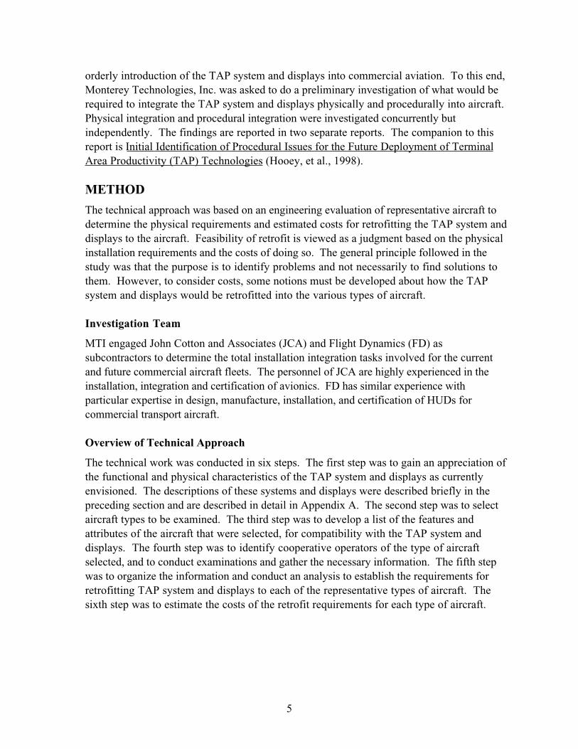
The controller CTAS tools (shown in Figure 1) include: Descent Advisor (DA) which
provides conflict free, fuel efficient descent information, Traffic Management Advisor
(TMA) which plans sequence and landing times, and a Final Approach Spacing Tool (FAST)
used to advise on accurate spacing on final approach. Flight deck modifications will include
adjustable FMS leg types that will support simple FMS route adjustments (e.g., downwind
leg length) in the TRACON airspace. While it is presently undecided, future
implementations may also include the addition of a datalink display and response buttons
that will support automatic loading of, and heads-up assessment and response to, uplinked
CTAS routes.
Figure 1. CTAS/FMS Integration.
7
Airborne Information for Lateral Spacing (AILS)
Airborne Information for Lateral Spacing (AILS), a Reduced Spacing Operations (RSO) sub-
element of the TAP program, will apply on-board precision navigation and communications
technology in conjunction with onboard safety surveillance systems [i.e., Traffic Alert and
Collision Avoidance System (TCAS)] to permit safer, reduced runway separation
requirements for Closely Spaced Parallel Approaches (CSPAs). At airports with parallel
runways spaced less than 4,300 feet apart, CSPAs may only be conducted in Visual
Meteorological Conditions (VMC), when both pilots can see the runway and the other
aircraft. In IMC, airport capacity is significantly reduced - only one runway may be used, or
the two runways may be used with aircraft spacing equivalent to the spacing used for a single
runway. The purpose of the AILS system is to maintain aircraft separation during closely
spaced parallel approaches of less than 4,300 ft separation in IMC. Traffic advisories and
resolution advisories (similar to TCAS) are provided to the flight crew to alert them of an
encroaching aircraft.
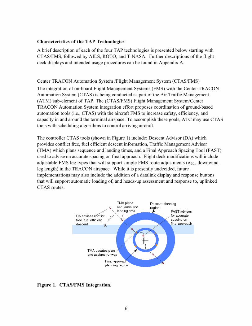
Both pilots primary flight display (PFD) will be modified to display the following: a parallel
traffic window which indicates the location (left or right) of the traffic; a slant range indicator,
which shows the distance (in hundreds of ft) between the ownship and the traffic; and a
horizontal motion arrow, which indicates that traffic is moving away from its centerline and
toward the ownship. A traffic advisory accompanied by an aural alert is issued if parallel
traffic executes a blunder that results in an intercept course. If the alerting system
determines that a maneuver is necessary to maintain separation, a resolution advisory is
issued and pitch & turn guidance cues and go-to bars appear on the PFD (see Figure 2, left).
160
2600
2000
023 00
140
150
180
200
100
120
20
80
2400
9
1
6
2
1
1
2
6
2200
150 3500
FD
G/A G/ATHR
3000 3000
GS157TAS157000°/00
000TRK MAG
333
– 01
3000
00 00.0Z00.0NM
TRAFFIC
Figure 2. Primary Flight Display (with AILS Resolution Advisory, left), AILSNavigation Display enhancements, right)
8
AILS also includes modifications to both pilots navigation display (ND) including: a parallel
runway and centerline cue, which indicates the location of the parallel runway and intended
path for the other aircraft; and a traffic trend vector which indicates what direction the traffic
is heading (see Figure 2, right).
Roll Out and Turn Off (ROTO)
Roll Out and Turn Off (ROTO) is a component of the Low Visibility Landing and Surface
Operations (LVLASO) sub-element of the TAP program. ROTO is being developed to
reduce the amount of time an aircraft needs to spend on the runway after landing. ROTO will
assist the pilot to quickly and safely exit the runway by providing visual guidance, braking
and turn advisories to the Captain via a head-up display (HUD).
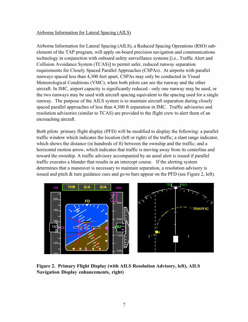
While airborne the pilot can set ROTO to either automatic or manual exit selection. In the
automatic mode, ROTO will select the first safe runway exit, while the manual mode allows
pilots to manually select a desired runway exit. The selected exit appears in the upper right
hand corner of the HUD (See Figure 3, left). At touch down, ROTO ground symbology
appears (See Figure 3, right) which provides current and predicted speed information.
Figure 3. ROTO Airborne Symbology (left) and Ground Symbology (right).
A ground speed error bar (on the left wing of the aircraft symbol) indicates whether the
deceleration rate is too high or too low for the selected turn off. As pilots approach the turn-
off, guidance is provided to indicate when the pilot should begin the turn. Two 2-second
trend vectors provide information to aid pilots in positioning the aircraft on the exit centerline
during the turnoff from the runway. If while in automatic mode, the pilot cannot decelerate
safely to make the selected exit, ROTO will automatically switch to the next turn off.
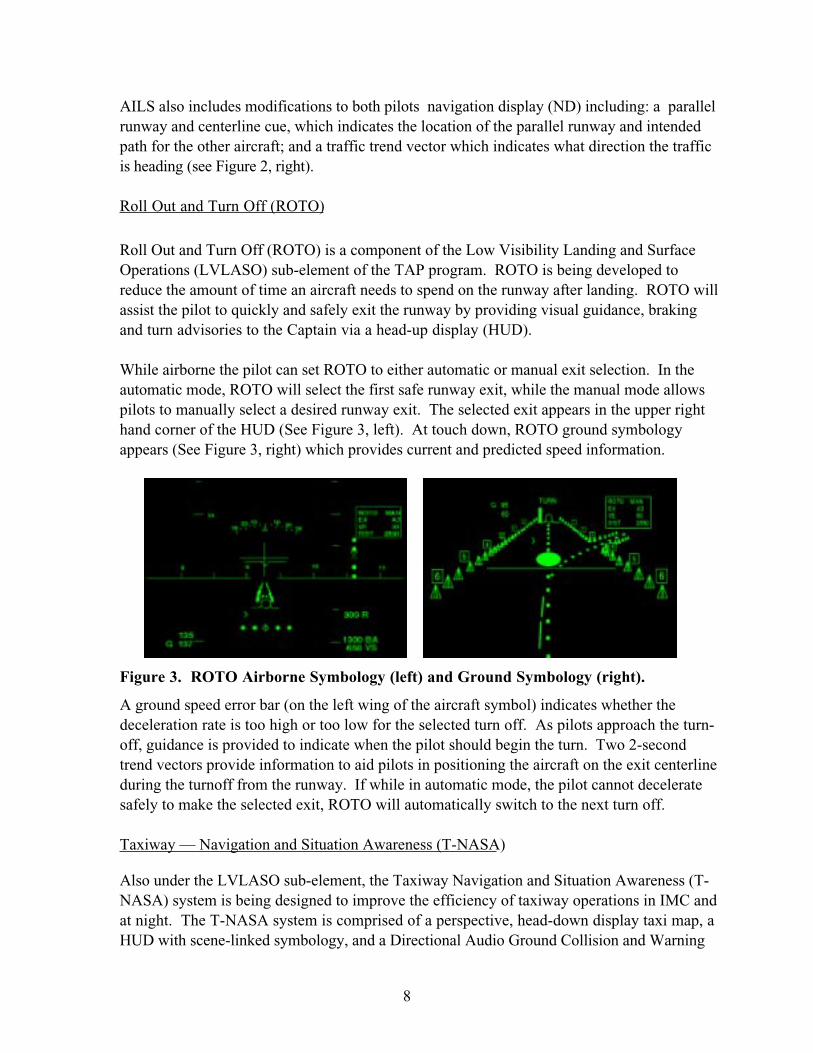
Taxiway — Navigation and Situation Awareness (T-NASA)
Also under the LVLASO sub-element, the Taxiway Navigation and Situation Awareness (T-
NASA) system is being designed to improve the efficiency of taxiway operations in IMC and
at night. The T-NASA system is comprised of a perspective, head-down display taxi map, a
HUD with scene-linked symbology, and a Directional Audio Ground Collision and Warning
9
System (GCAW). All components are designed to increase taxi speed, route navigation
accuracy, and situational awareness in low visibility conditions. It is expected that near term
implementation of T-NASA will augment, but not replace, current day Ground Control
operations. However, future implementations are also being considered that may place a
greater emphasis on datalink communications over voice communications.
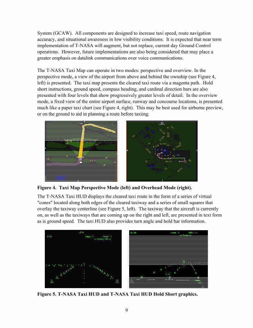
The T-NASA Taxi Map can operate in two modes: perspective and overview. In the
perspective mode, a view of the airport from above and behind the ownship (see Figure 4,
left) is presented. The taxi map presents the cleared taxi route via a magenta path. Hold
short instructions, ground speed, compass heading, and cardinal direction bars are also
presented with four levels that show progressively greater levels of detail. In the overview
mode, a fixed view of the entire airport surface, runway and concourse locations, is presented
much like a paper taxi chart (see Figure 4, right). This may be best used for airborne preview,
or on the ground to aid in planning a route before taxiing.
Figure 4. Taxi Map Perspective Mode (left) and Overhead Mode (right).
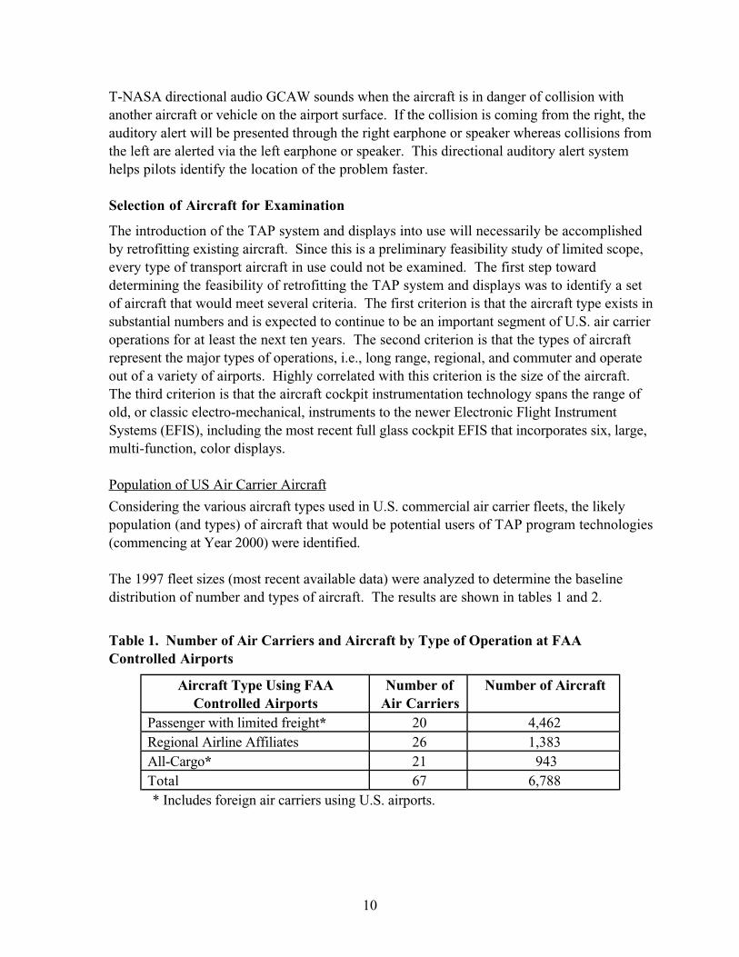
The T-NASA Taxi HUD displays the cleared taxi route in the form of a series of virtual
"cones" located along both edges of the cleared taxiway and a series of small squares that
overlay the taxiway centerline (see Figure 5, left). The taxiway that the aircraft is currently
on, as well as the taxiways that are coming up on the right and left, are presented in text form
as is ground speed. The taxi HUD also provides turn angle and hold bar information.
Figure 5. T-NASA Taxi HUD and T-NASA Taxi HUD Hold Short graphics.
10
T-NASA directional audio GCAW sounds when the aircraft is in danger of collision with
another aircraft or vehicle on the airport surface. If the collision is coming from the right, the
auditory alert will be presented through the right earphone or speaker whereas collisions from
the left are alerted via the left earphone or speaker. This directional auditory alert system
helps pilots identify the location of the problem faster.
Selection of Aircraft for Examination
The introduction of the TAP system and displays into use will necessarily be accomplished
by retrofitting existing aircraft. Since this is a preliminary feasibility study of limited scope,
every type of transport aircraft in use could not be examined. The first step toward
determining the feasibility of retrofitting the TAP system and displays was to identify a set
of aircraft that would meet several criteria. The first criterion is that the aircraft type exists in
substantial numbers and is expected to continue to be an important segment of U.S. air carrier
operations for at least the next ten years. The second criterion is that the types of aircraft
represent the major types of operations, i.e., long range, regional, and commuter and operate
out of a variety of airports. Highly correlated with this criterion is the size of the aircraft.
The third criterion is that the aircraft cockpit instrumentation technology spans the range of
old, or classic electro-mechanical, instruments to the newer Electronic Flight Instrument
Systems (EFIS), including the most recent full glass cockpit EFIS that incorporates six, large,
multi-function, color displays.
Population of US Air Carrier Aircraft
Considering the various aircraft types used in U.S. commercial air carrier fleets, the likely
population (and types) of aircraft that would be potential users of TAP program technologies
(commencing at Year 2000) were identified.
The 1997 fleet sizes (most recent available data) were analyzed to determine the baseline
distribution of number and types of aircraft. The results are shown in tables 1 and 2.
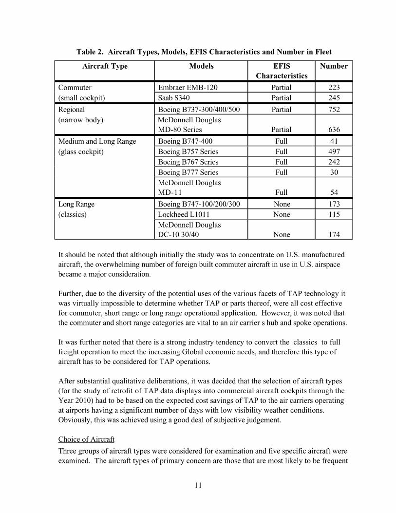
Table 1. Number of Air Carriers and Aircraft by Type of Operation at FAAControlled Airports
Aircraft Type Using FAAControlled Airports
Number ofAir Carriers
Number of Aircraft
Passenger with limited freight* 20 4,462
Regional Airline Affiliates 26 1,383
All-Cargo* 21 943
Total 67 6,788
* Includes foreign air carriers using U.S. airports.
11
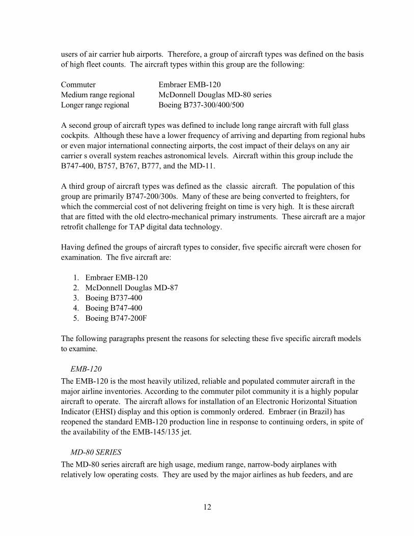
Table 2. Aircraft Types, Models, EFIS Characteristics and Number in Fleet
Aircraft Type Models EFISCharacteristics
Number
Commuter Embraer EMB-120 Partial 223
(small cockpit) Saab S340 Partial 245
Regional Boeing B737-300/400/500 Partial 752
(narrow body) McDonnell Douglas
MD-80 Series Partial 636
Medium and Long Range Boeing B747-400 Full 41
(glass cockpit) Boeing B757 Series Full 497
Boeing B767 Series Full 242
Boeing B777 Series Full 30
McDonnell Douglas
MD-11 Full 54
Long Range Boeing B747-100/200/300 None 173
(classics) Lockheed L1011 None 115
McDonnell Douglas
DC-10 30/40 None 174
It should be noted that although initially the study was to concentrate on U.S. manufactured
aircraft, the overwhelming number of foreign built commuter aircraft in use in U.S. airspace
became a major consideration.
Further, due to the diversity of the potential uses of the various facets of TAP technology it
was virtually impossible to determine whether TAP or parts thereof, were all cost effective
for commuter, short range or long range operational application. However, it was noted that
the commuter and short range categories are vital to an air carrier s hub and spoke operations.
It was further noted that there is a strong industry tendency to convert the classics to full
freight operation to meet the increasing Global economic needs, and therefore this type of
aircraft has to be considered for TAP operations.
After substantial qualitative deliberations, it was decided that the selection of aircraft types
(for the study of retrofit of TAP data displays into commercial aircraft cockpits through the
Year 2010) had to be based on the expected cost savings of TAP to the air carriers operating
at airports having a significant number of days with low visibility weather conditions.
Obviously, this was achieved using a good deal of subjective judgement.
Choice of Aircraft
Three groups of aircraft types were considered for examination and five specific aircraft were
examined. The aircraft types of primary concern are those that are most likely to be frequent
12
users of air carrier hub airports. Therefore, a group of aircraft types was defined on the basis
of high fleet counts. The aircraft types within this group are the following:
Commuter Embraer EMB-120
Medium range regional McDonnell Douglas MD-80 series
Longer range regional Boeing B737-300/400/500
A second group of aircraft types was defined to include long range aircraft with full glass
cockpits. Although these have a lower frequency of arriving and departing from regional hubs
or even major international connecting airports, the cost impact of their delays on any air
carrier s overall system reaches astronomical levels. Aircraft within this group include the
B747-400, B757, B767, B777, and the MD-11.
A third group of aircraft types was defined as the classic aircraft. The population of this
group are primarily B747-200/300s. Many of these are being converted to freighters, for
which the commercial cost of not delivering freight on time is very high. It is these aircraft
that are fitted with the old electro-mechanical primary instruments. These aircraft are a major
retrofit challenge for TAP digital data technology.
Having defined the groups of aircraft types to consider, five specific aircraft were chosen for
examination. The five aircraft are:
1. Embraer EMB-120
2. McDonnell Douglas MD-87
3. Boeing B737-400
4. Boeing B747-400
5. Boeing B747-200F
The following paragraphs present the reasons for selecting these five specific aircraft models
to examine.
EMB-120
The EMB-120 is the most heavily utilized, reliable and populated commuter aircraft in the
major airline inventories. According to the commuter pilot community it is a highly popular
aircraft to operate. The aircraft allows for installation of an Electronic Horizontal Situation
Indicator (EHSI) display and this option is commonly ordered. Embraer (in Brazil) has
reopened the standard EMB-120 production line in response to continuing orders, in spite of
the availability of the EMB-145/135 jet.
MD-80 SERIES
The MD-80 series aircraft are high usage, medium range, narrow-body airplanes with
relatively low operating costs. They are used by the major airlines as hub feeders, and are
13
being sought after by second tier reduced fare airlines for extended service. Furthermore,
the later models optionally include an Electronic Attitude Director Indicator (EADI) and an
Electronic Horizontal Situation Indicator (EHSI). The MD-87 was selected to represent this
group because of its availability for examination.
Boeing B737-300/400/500
The generic B737 aircraft is a workhorse of the longer range regional services and is also
popular as a short range shuttle aircraft which supports hub and spoke operations. In terms
of total regional aircraft availability, it is the most popular aircraft in production. The B737-
300/400/500 series versions all provide for installation of an EADI and an EHSI. However,
many are still being purchased with electro-mechanical attitude and guidance instruments.
Some B737s have been modified to include a HUD. The next generation of B737s will have a
full glass cockpit. The B737-400 was selected to represent this group because of its
availability for examination.
B747-400, B757, B767, B777, MD-11
The B747-400, with a full-up glass cockpit comprising six 8 x 8 multi-function color
displays, is representative of the primary and secondary instrument/display technology
present in the B757, B767, B777, and MD-11 families of aircraft. TAP retrofit issues for the
B747-400 will be similar to those for these other aircraft. Therefore, the B747-400 was
selected to represent this aircraft group.
B747-100/200/300, L-1011, DC-10 30/40
The B747-200/300 classic aircraft are representative of a family of valuable aircraft that have
been depreciated to zero several times by their various owners, and for which the life is being
maintained and extended to an indeterminate date. The B747-100 series are being retired to
third world air carriers, whereas the B747-200 series is being sought by the air cargo industry
for conversion to full freighters. On the other hand, the smaller fleet of 747-300s with the
extended upper deck and long range endurance is being sought by cost conscious
non-scheduled, long range, passenger, and charter operators. Modification of the existing
analog displays to EADI & EHSI is already in progress by several second tier air carriers.
They have commenced aggressive modernization programs to ensure that the aircraft can use
the same airspace with identical navigation accuracy as their full glass cockpit equivalents.
Therefore this type of modernization encompasses provision for some, if not all of the TAP
requirements. The L-1011 and DC-10 aircraft were also considered, but the B747-200 was
selected to represent this group.
Aircraft Items to be Examined for TAP System Compatibility
Implementation of TAP functionality requires certain external and internal data sources,
computational resources, symbol generation capability, controls to interact with the systems,
and display devices to present the information. In addition to the TAP specific software, a
great deal of new software is likely to be required for integration of TAP functionality into
14
existing aircraft systems. This task focuses on identifying the elements of aircraft hardware
and software that are to be considered in the examination for TAP system compatibility.
In general the technical engineering challenge in integrating TAP into existing aircraft is a more
complex matter than might be recognized. This is in spite of the fact that the changes are
seemingly simple. They primarily involve a change in data flow for the panel mounted
displays, the addition of a HUD, and the potential upgrading of various aircraft sensors for
each aircraft type (to provide the data accuracy and resolution required for the display of
TAP information). The issue is more complex as a result of integration with an existing
system, which typically already has many interconnections for functional performance as
well as for internal monitoring.
However, beyond the purely engineering considerations is the issue of certification of the
modified aircraft. The certification cost for the new TAP capabilities must include not only
the direct costs for verification and validation of new hardware and software, but must also
include the cost of re-verification of all previously existing software that could be affected by
the addition of the TAP system. This is typically a larger undertaking than one imagines,
because it requires verification that none of the existing functionality, integrity and
availability has been adversely affected. Verification includes both analysis and testing.
The broad objectives to be accomplished during the aircraft examinations are the following:
1. Determine what existing equipment must be moved or displaced to allow installation of
TAP equipment. The scope includes but is not limited to displays, processors, sensors,
and connectors.
2. Determine if existing symbol generation and display capability (primarily capacity) is
adequate where existing avionics equipment, hardware and software has to be adapted for
use with the TAP system and displays. Where existing capacity is inadequate, identify
required upgrades or enhancements.
3. Determine adequacy of available processing capability and memory needed to support the
TAP system and displays, and identify shortfalls.
4. Determine if sufficient data transfer for TAP display information is available. Where
existing capability is inadequate, identify required upgrades or enhancements.
5. Determine software modifications necessary to support TAP display operation. Identify
the scope of changes required, including estimating the effort or costs required for: a)
modifications to the code; b) documentation of changes; and c) the re-certification
process.
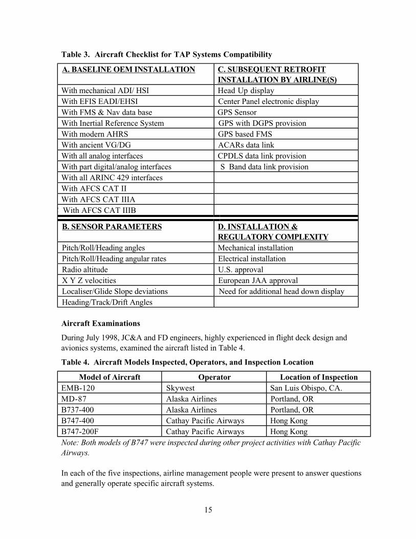
Scope of Aircraft Examinations for TAP System Compatibility
A checklist for aircraft examinations is given in Table 3.
15
Table 3. Aircraft Checklist for TAP Systems Compatibility
A. BASELINE OEM INSTALLATION C. SUBSEQUENT RETROFITINSTALLATION BY AIRLINE(S)
With mechanical ADI/ HSI Head Up display
With EFIS EADI/EHSI Center Panel electronic display
With FMS & Nav data base GPS Sensor
With Inertial Reference System GPS with DGPS provision
With modern AHRS GPS based FMS
With ancient VG/DG ACARs data link
With all analog interfaces CPDLS data link provision
With part digital/analog interfaces S Band data link provision
With all ARINC 429 interfaces
With AFCS CAT II
With AFCS CAT IIIA
C With AFCS CAT IIIB
B. SENSOR PARAMETERS D. INSTALLATION ®ULATORY COMPLEXITY
Pitch/Roll/Heading angles Mechanical installation
Pitch/Roll/Heading angular rates Electrical installation
Radio altitude U.S. approval
X Y Z velocities European JAA approval
Localiser/Glide Slope deviations Need for additional head down display
Heading/Track/Drift Angles
Aircraft Examinations
During July 1998, JC&A and FD engineers, highly experienced in flight deck design and
avionics systems, examined the aircraft listed in Table 4.
Table 4. Aircraft Models Inspected, Operators, and Inspection Location
Model of Aircraft Operator Location of InspectionEMB-120 Skywest San Luis Obispo, CA.
MD-87 Alaska Airlines Portland, OR
B737-400 Alaska Airlines Portland, OR
B747-400 Cathay Pacific Airways Hong Kong
B747-200F Cathay Pacific Airways Hong Kong
Note: Both models of B747 were inspected during other project activities with Cathay PacificAirways.
In each of the five inspections, airline management people were present to answer questions
and generally operate specific aircraft systems.
16
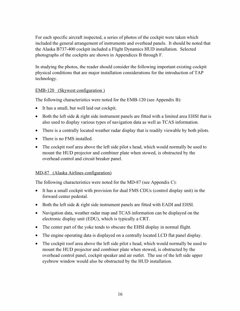
For each specific aircraft inspected, a series of photos of the cockpit were taken which
included the general arrangement of instruments and overhead panels. It should be noted that
the Alaska B737-400 cockpit included a Flight Dynamics HUD installation. Selected
photographs of the cockpits are shown in Appendices B through F.
In studying the photos, the reader should consider the following important existing cockpit
physical conditions that are major installation considerations for the introduction of TAP
technology.
EMB-120 (Skywest configuration )
The following characteristics were noted for the EMB-120 (see Appendix B):
• It has a small, but well laid out cockpit.
• Both the left side & right side instrument panels are fitted with a limited area EHSI that is
also used to display various types of navigation data as well as TCAS information.
• There is a centrally located weather radar display that is readily viewable by both pilots.
• There is no FMS installed.
• The cockpit roof area above the left side pilot s head, which would normally be used to
mount the HUD projector and combiner plate when stowed, is obstructed by the
overhead control and circuit breaker panel.
MD-87 (Alaska Airlines configuration)
The following characteristics were noted for the MD-87 (see Appendix C):
• It has a small cockpit with provision for dual FMS CDUs (control display unit) in the
forward center pedestal.
• Both the left side & right side instrument panels are fitted with EADI and EHSI.
• Navigation data, weather radar map and TCAS information can be displayed on the
electronic display unit (EDU), which is typically a CRT.
• The center part of the yoke tends to obscure the EHSI display in normal flight.
• The engine operating data is displayed on a centrally located LCD flat panel display.
• The cockpit roof area above the left side pilot s head, which would normally be used to
mount the HUD projector and combiner plate when stowed, is obstructed by the
overhead control panel, cockpit speaker and air outlet. The use of the left side upper
eyebrow window would also be obstructed by the HUD installation.
17
B737-400 (Alaska Airlines configuration)
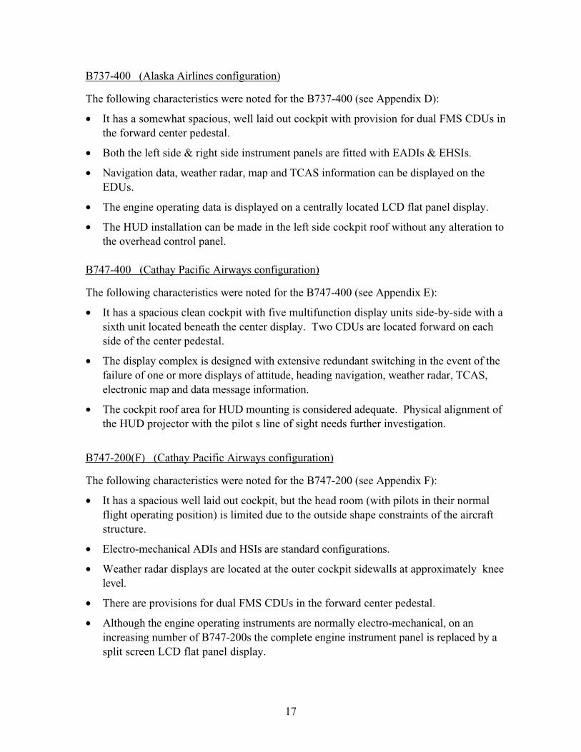
The following characteristics were noted for the B737-400 (see Appendix D):
• It has a somewhat spacious, well laid out cockpit with provision for dual FMS CDUs in
the forward center pedestal.
• Both the left side & right side instrument panels are fitted with EADIs & EHSIs.
• Navigation data, weather radar, map and TCAS information can be displayed on the
EDUs.
• The engine operating data is displayed on a centrally located LCD flat panel display.
• The HUD installation can be made in the left side cockpit roof without any alteration to
the overhead control panel.
B747-400 (Cathay Pacific Airways configuration)
The following characteristics were noted for the B747-400 (see Appendix E):
• It has a spacious clean cockpit with five multifunction display units side-by-side with a
sixth unit located beneath the center display. Two CDUs are located forward on each
side of the center pedestal.
• The display complex is designed with extensive redundant switching in the event of the
failure of one or more displays of attitude, heading navigation, weather radar, TCAS,
electronic map and data message information.
• The cockpit roof area for HUD mounting is considered adequate. Physical alignment of
the HUD projector with the pilot s line of sight needs further investigation.
B747-200(F) (Cathay Pacific Airways configuration)
The following characteristics were noted for the B747-200 (see Appendix F):
• It has a spacious well laid out cockpit, but the head room (with pilots in their normal
flight operating position) is limited due to the outside shape constraints of the aircraft
structure.
• Electro-mechanical ADIs and HSIs are standard configurations.
• Weather radar displays are located at the outer cockpit sidewalls at approximately knee
level.
• There are provisions for dual FMS CDUs in the forward center pedestal.
• Although the engine operating instruments are normally electro-mechanical, on an
increasing number of B747-200s the complete engine instrument panel is replaced by a
split screen LCD flat panel display.
18
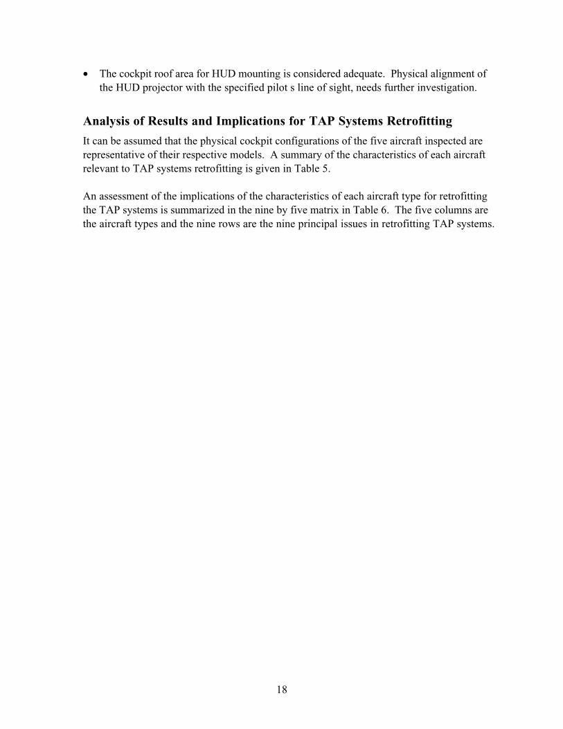
• The cockpit roof area for HUD mounting is considered adequate. Physical alignment of
the HUD projector with the specified pilot s line of sight, needs further investigation.
Analysis of Results and Implications for TAP Systems Retrofitting
It can be assumed that the physical cockpit configurations of the five aircraft inspected are
representative of their respective models. A summary of the characteristics of each aircraft
relevant to TAP systems retrofitting is given in Table 5.
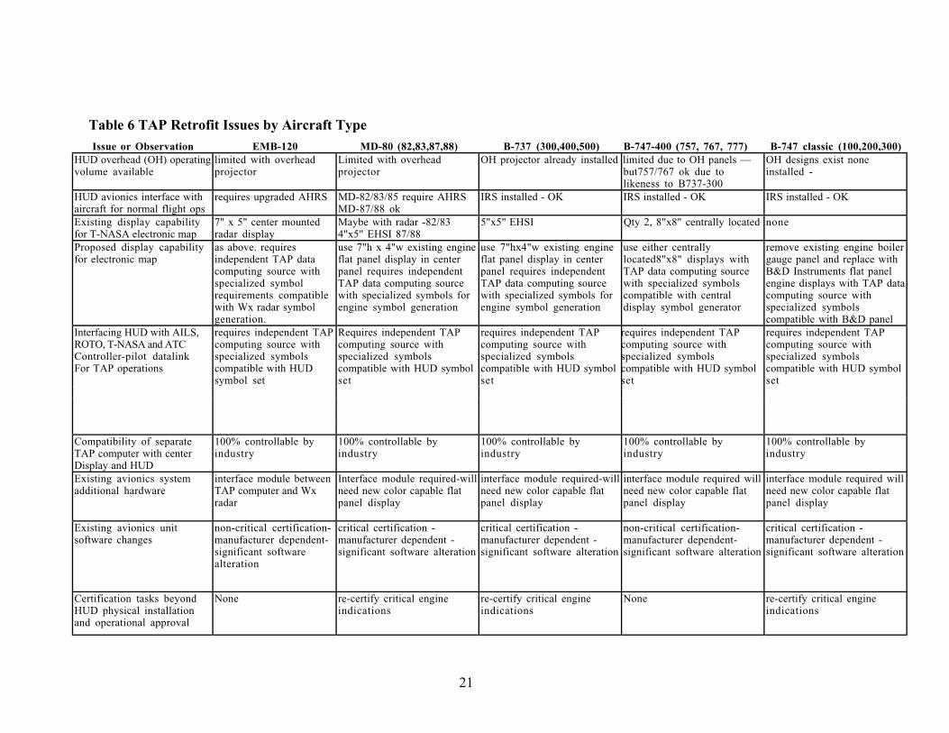
An assessment of the implications of the characteristics of each aircraft type for retrofitting
the TAP systems is summarized in the nine by five matrix in Table 6. The five columns are
the aircraft types and the nine rows are the nine principal issues in retrofitting TAP systems.
19
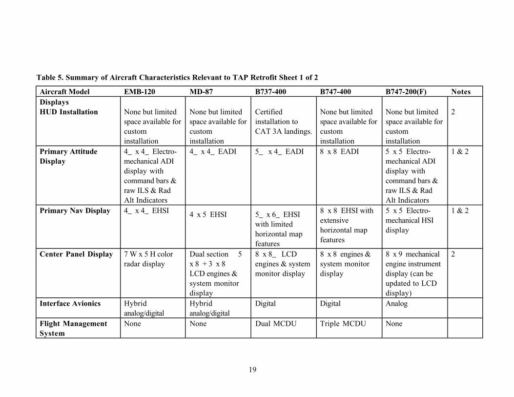
Table 5. Summary of Aircraft Characteristics Relevant to TAP Retrofit Sheet 1 of 2
Aircraft Model EMB-120 MD-87 B737-400 B747-400 B747-200(F) NotesDisplaysHUD Installation None but limited
space available for
custom
installation
None but limited
space available for
custom
installation
Certified
installation to
CAT 3A landings.
None but limited
space available for
custom
installation
None but limited
space available for
custom
installation
2
Primary AttitudeDisplay
4_ x 4_ Electro-
mechanical ADI
display with
command bars &
raw ILS & Rad
Alt Indicators
4_ x 4_ EADI 5_ x 4_ EADI 8 x 8 EADI 5 x 5 Electro-
mechanical ADI
display with
command bars &
raw ILS & Rad
Alt Indicators
1 & 2
Primary Nav Display 4_ x 4_ EHSI4 x 5 EHSI 5_ x 6_ EHSI
with limited
horizontal map
features
8 x 8 EHSI with
extensive
horizontal map
features
5 x 5 Electro-
mechanical HSI
display
1 & 2
Center Panel Display 7 W x 5 H color
radar display
Dual section 5
x 8 + 3 x 8
LCD engines &
system monitor
display
8 x 8_ LCD
engines & system
monitor display
8 x 8 engines &
system monitor
display
8 x 9 mechanical
engine instrument
display (can be
updated to LCD
display)
2
Interface Avionics Hybrid
analog/digital
Hybrid
analog/digital
Digital Digital Analog
Flight ManagementSystem
None None Dual MCDU Triple MCDU None
20
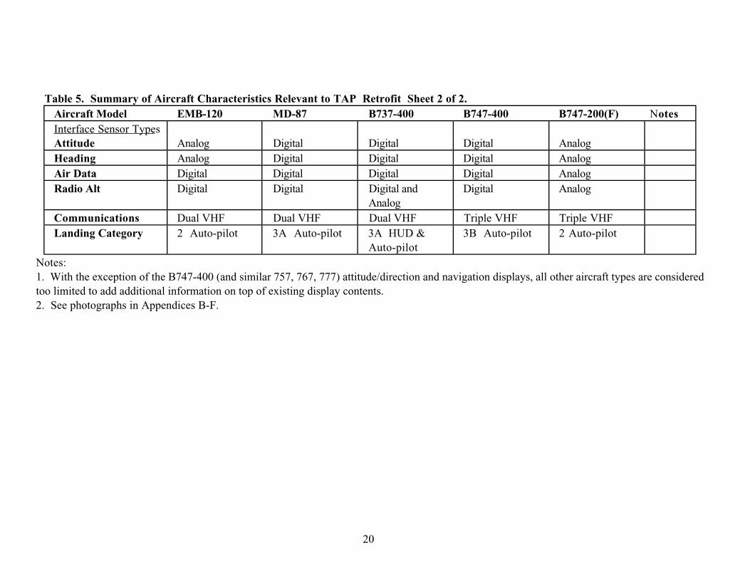
Table 5. Summary of Aircraft Characteristics Relevant to TAP Retrofit Sheet 2 of 2.Aircraft Model EMB-120 MD-87 B737-400 B747-400 B747-200(F) NotesInterface Sensor Types
Attitude Analog Digital Digital Digital Analog
Heading Analog Digital Digital Digital Analog
Air Data Digital Digital Digital Digital Analog
Radio Alt Digital Digital Digital and
Analog
Digital Analog
Communications Dual VHF Dual VHF Dual VHF Triple VHF Triple VHF
Landing Category 2 Auto-pilot 3A Auto-pilot 3A HUD &
Auto-pilot
3B Auto-pilot 2 Auto-pilot
Notes:
1. With the exception of the B747-400 (and similar 757, 767, 777) attitude/direction and navigation displays, all other aircraft types are considered
too limited to add additional information on top of existing display contents.
2. See photographs in Appendices B-F.
21
Table 6 TAP Retrofit Issues by Aircraft TypeIssue or Observation EMB-120 MD-80 (82,83,87,88) B-737 (300,400,500) B-747-400 (757, 767, 777) B-747 classic (100,200,300)
HUD overhead (OH) operating
volume available
limited with overhead
projector
Limited with overhead
projector
OH projector already installed limited due to OH panels —
but757/767 ok due to
likeness to B737-300
OH designs exist none
installed -
HUD avionics interface with
aircraft for normal flight ops
requires upgraded AHRS MD-82/83/85 require AHRS
MD-87/88 ok
IRS installed - OK IRS installed - OK IRS installed - OK
Existing display capability
for T-NASA electronic map
7" x 5" center mounted
radar display
Maybe with radar -82/83
4"x5" EHSI 87/88
5"x5" EHSI Qty 2, 8"x8" centrally located none
Proposed display capability
for electronic map
as above. requires
independent TAP data
computing source with
specialized symbol
requirements compatible
with Wx radar symbol
generation.
use 7"h x 4"w existing engine
flat panel display in center
panel requires independent
TAP data computing source
with specialized symbols for
engine symbol generation
use 7"hx4"w existing engine
flat panel display in center
panel requires independent
TAP data computing source
with specialized symbols for
engine symbol generation
use either centrally
located8"x8" displays with
TAP data computing source
with specialized symbols
compatible with central
display symbol generator
remove existing engine boiler
gauge panel and replace with
B&D Instruments flat panel
engine displays with TAP data
computing source with
specialized symbols
compatible with B&D panel
requires independent TAP
computing source with
specialized symbols
compatible with HUD symbol
set
Interfacing HUD with AILS,
ROTO, T-NASA and ATC
Controller-pilot datalink
For TAP operations
requires independent TAP
computing source with
specialized symbols
compatible with HUD
symbol set
Requires independent TAP
computing source with
specialized symbols
compatible with HUD symbol
set
requires independent TAP
computing source with
specialized symbols
compatible with HUD symbol
set
requires independent TAP
computing source with
specialized symbols
compatible with HUD symbol
set
Compatibility of separate
TAP computer with center
Display and HUD
100% controllable by
industry
100% controllable by
industry
100% controllable by
industry
100% controllable by
industry
100% controllable by
industry
interface module required will
need new color capable flat
panel display
Existing avionics system
additional hardware
interface module between
TAP computer and Wx
radar
Interface module required-will
need new color capable flat
panel display
interface module required-will
need new color capable flat
panel display
interface module required will
need new color capable flat
panel display
Existing avionics unit
software changes
non-critical certification-
manufacturer dependent-
significant software
alteration
critical certification -
manufacturer dependent -
significant software alteration
critical certification -
manufacturer dependent -
significant software alteration
non-critical certification-
manufacturer dependent-
significant software alteration
critical certification -
manufacturer dependent -
significant software alteration
Certification tasks beyond
HUD physical installation
and operational approval
None re-certify critical engine
indications
re-certify critical engine
indications
None re-certify critical engine
indications
22
Retrofitting of all Types of Aircraft is Potentially Feasible
An important, general conclusion is that the TAP systems and displays, both head-up and
panel mounted, could be retrofitted into of all five types of aircraft examined. A first take on
the retrofit problem is that each aircraft type will require significant, unique changes and
additions to accommodate the TAP systems. The work will involve physical installation,
requiring, in some cases, movement of existing equipment, software additions and
modifications, and re-certification of the software. However, the work and costs will vary
with type of aircraft. Retrofitting the long range, classic type aircraft would be the most
expensive because of hardware and software additions required. Since there is no underlying
software system, all costs for installation and certification would be based on new equipment.
Retrofitting the newest, glass-cockpit type aircraft, e.g., B737-400/800, B767, B747-400,
B777, etc. would likely be the next most expensive. The equipment installation costs would
be relatively small but the certification, or rather, the re-certification of affected software,
would be very expensive, even if amortized over a number of aircraft. A recognized major
cost of adding new equipment such as a HUD to an aircraft is the process of gaining the
airworthiness & operational certification. However, a cost that is often overlooked is the
effort required to re-certify the changes to existing hardware and software necessitated by the
introduction of the new technology. For the most modern glass cockpits, the original
software used for the EFIS instruments and displays is complex and critical.
TAP Retrofitting Issues
The main TAP retrofit issues are 1) fitting a HUD; 2) provide a panel display; and 3) provide
for the TAP avionics including the necessary data inputs, computational capability and
symbol generation required by all the TAP systems.
HUD
The HUD is a common requirement for at least the AILS, ROTO & T-NASA functions.
Based on the information in Table 6, the HUD physical installation must necessarily be
unique for each cockpit type. However the main difficulty in HUD physical installation will
be for the EMB-120 and MD-80. Also, only the EMB-120 and early MD-80s require an
upgrade to their attitude and heading reference system (AHRS).
Panel Mounted Display
A reasonable assumption is that at least a 6 x 6 panel display is the minimum size required
for the T-NASA map display. Except for the 747-400 and aircraft with similar glass cockpits
the displays are all smaller in at least one dimension. The EMB-120, MD-87 and B747-200
have, or can have, a flat panel display between 4.5 x 4.5 and 5.0 x 5.0 . It is questionable
if these displays are large enough for a useful T-NASA map display. Alternatively, the panel
mounted display requirement can be met by the EMB-120 7 x 5 radar display. An MD-80
radar display may also serve for the T-NASA map in this aircraft. The largest display in the
737-300, 400, 500 is the 5.75 x 4.5 EADI. For the older aircraft, replacing the electro-
23
mechanical engine instruments with a 4 wide x 7 high display may provide a large enough
display for the T-NASA electronic map.
An alternative is to add a new panel-mounted display. A flat panel 6 x 6 color LCD
display can be installed in the center instrument panel on at least four of the aircraft types
(EMB-120, MD-80 series, B737-300/400/500 and B747 classic). Note that the B747-400,
B757, B767, B777 already have glass displays in the center instrument panel location
whereas an LCD flat display panel of the same type has already been installed on several
B747-classic aircraft. Obviously an intelligent, software-controlled sharing of the display for
TAP data and engine data is a prerequisite for this arrangement.
TAP Avionics
In all five types of aircraft, additional computing and symbol generation capabilities are
required. This is expected since this is the heart of the TAP systems and they are unique
relative to current information displayed in the cockpits. A TAP common avionics unit can
be specified to suit the various aircraft configurations for the TAP CTAS, AILS, ROTO & T-
NASA systems as well as the various operating modes. The avionics unit can have a
common but partitioned software program for CTAS, AILS, ROTO and T-NASA with
standard interfaces to the HUD and the T-NASA display controller. This would also
provide for the flexibility of selection or deletion of the various TAP features considered
necessary for air carrier operators to suit their individual operational needs.
Alternative to Individual Retrofitting by Aircraft Type
At the outset of this study it was expected that finding a substantially common, one-size
fits all for
TAP system retrofitting would be impractical and costly relative to integration schemes
specific to each aircraft type. However, as the analysis of the requirements for each aircraft
type proceeded, it became evident that the collective costs would be great for individual initial
type certification of the new hardware and software and for re-certification of the affected,
existing hardware and software. Any practical approach must necessarily focus on reducing
the multitude of differences (summarized in Tables 5 and 6) that must be addressed
individually to retrofit the TAP systems. Consequently, the possibility of implementing the
TAP systems as a stand-alone, add-on unit appears to be the more attractive option.
As a largely independent unit, the TAP software would have minimal interaction with the
existing aircraft software. Being aircraft-independent, the TAP systems would require only
one major certification cycle and preclude costly initial certifications for a multiplicity of
aircraft types. This design approach would also reduce the otherwise considerable
re-certification costs.
The proposal of a common TAP installation architecture for multiple types of aircraft is
predicated on well established commercial air carrier industry practice to accommodate the
24
introduction new avionics technologies. In practice, an authoritative body, e.g., the Airlines
Electronic Engineering Committee (AEEC) will specify common installation conceptual
guidelines applicable to a variety of aircraft types and model configurations.
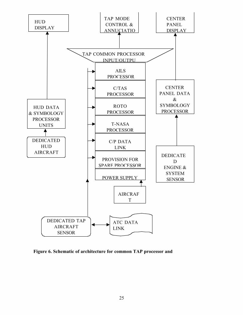
Tap Installation Considerations
The following proceeds on the assumption that a common TAP architecture will be the most
acceptable and cost effective way of introducing and retrofitting the various (but selectable)
TAP features for U.S. commercial air carriers. Figure 6 is a diagrammatic representation of a
concept for a common TAP installation architecture.
There are four generic topics that have to be considered in the development of the common
installation specification for the TAP systems.
1. Installation of production HUDs in various cockpits
2. Development of the TAP common processor units and display
3. Installation of the TAP common processor and display
4. Hardware and software regulatory certification of the avionics units and the TAP
installation
25
TAP MODE
CONTROL &
ANNUCIATIO
CENTER
PANEL
DISPLAY
DEDICATE
D
ENGINE &
SYSTEM
SENSOR
CENTER
PANEL DATA
&
SYMBOLOGY
PROCESSOR
TAP COMMON PROCESSOR
PROVISION FOR
SPARE PROCESSOR
C/P DATA
LINK
T-NASA
PROCESSOR
ROTO
PROCESSOR
INPUT/OUTPU
AILS
PROCESSOR
POWER SUPPLY
C/TAS
PROCESSOR
AIRCRAF
T
DEDICATED TAP
AIRCRAFT
SENSOR
HUD
DISPLAY
HUD DATA
& SYMBOLOGY
PROCESSOR
UNITS
DEDICATED
HUD
AIRCRAFT
ATC DATA
LINK
Figure 6. Schematic of architecture for common TAP processor and
26
Installation of Production Head Up Displays
HUD s are a generic part of most military tactical aircraft, but have only recently been
adopted in significant numbers by air carriers. The principal advantage of a HUD on a civil
transport aircraft is the ability to take-off and land under lower visibility conditions than
permitted with conventional instruments. For example, to take off without a HUD the
Runway Visual Range (RVR) must be at least 700 ft, but with a HUD it can be as low as 300
ft. (Note that there are no autopilot take-offs.) Low visibility approaches and landings can
be achieved in a variety of ways. The least sophisticated alternative is a manually flown
approach using head-down instruments. Other alternatives (with increasing levels of control
sophistication) are a coupled autopilot approach, a manually flown approach using a HUD
(with guidance), and an approach using an autoland . Approved weather minima are
different for each of these control alternatives. The weather minima for transport aircraft are
defined in terms of Categories of approach, which are themselves defined in terms of a
minimum Decision Height (DH) and a minimum RVR. These Categories are defined below,
along with the current minimum approved control means for each Category.
Category 1:
DH at least 200 ft, and RVR at least 2400 ft (1800 ft with certain airport lighting)
(can be flown manually without guidance, using HUD or head down displays)
Category 2:
DH below 200 ft (but not less than 100 ft), and RVR at least 1200 ft
(if flown manually must use flight director guidance on HUD or head down display)
Category 3a:
DH below 100 ft (typically 50 ft) and/or RVR below 1200 ft (but not less than 700 ft)
(if flown manually must use flight director guidance on a HUD)
Category 3b:
no DH (or DH below 50 ft) and/or RVR less than 700 ft (but not less than 150 ft)
(must use a fail-operational autopilot, or a HUD with guidance)
It is also becoming accepted that HUDs help maintain situational awareness. For the TAP
application, symbology that is conformal to the outside scene is required for the ROTO and
T-NASA systems. However, other systems are being developed that do not have completely
conformal displays.
There are several generic requirements for installing a HUD in an aircraft. The physical
design requirements are to provide approximately a 24 degree high by 30 degree wide field of
view with adequate head clearance and low obscuration, with HUD symbology readable
under all lighting conditions. These translate into mechanical and optical design requirements.
The requirement for HUD symbology to be conformal with the outside world translates into
a need for accurate alignments of overhead projector, combiner (for displaying the projected
symbology) and the design eye point. A requirement for the pilot to see the full display
27
while allowing normal head motions leads to an eye box requirement, which translates into
optics design requirements and combiner geometry.
Functionally, each system is custom designed to provide the required parameters for flight
control and monitoring from whatever sensor set is available. Additional sensors may have to
be installed to support data redundancy and TAP requirements.
HUD installations in commercial aircraft include, among other things, an overhead projector
and a combiner. With regard to the installation of an overhead projector the task can be
characterized as embedding it in the ceiling. As the aircraft structure in this area is different
on every aircraft, the physical design considerations for installing a HUD into a limited
overhead volume is unique to each aircraft type. To achieve an acceptable installation, the
design must integrate two elements. First the design of the mechanical hardware of the
overhead projector (which houses the optical lens array) must allow for adequate pilot head
clearance for a wide range of pilot sizes. Second, the relative position, distance, and angles,
among the projector, combiner, and design eye point will affect the projector and combiner
positioning, and the projector lens and combiner optical designs.
Using an iterative process, a solution can be found for most aircraft types. Problems in
achieving an acceptable design for one element can be resolved by design modifications in
other elements. However, it should be noted that each installation has to be calibrated to
eliminate effects of manufacturing variability.
The mechanical design and installation of a HUD is always a challenging task. However in
addition to the physical considerations, the software generating the symbology has to be
functionally tuned to the dynamic performance of each aircraft type, and sometimes of each
aircraft model within a specific type. This often involves the installation of more accurate
digital and occasionally analog sensors than those for which the aircraft type/model was
originally certified.
Development of the Tap Common Processor and Display
Avionics and displays that have been functionally characterized by the Airlines Electronics
Engineering Committee (AEEC) are competitively manufactured in the U.S. for air carriers.
Companies such as Allied Signal, Honeywell, Rockwell Collins and several other companies
manufacture to high standards of design integrity and workmanship to meet the exacting FAA
certification requirements. Therefore, little needs to be said about the physical or hardware
development of a modular avionics TAP Processor Unit. Similarly, nothing more need be
said about the airworthiness or operational requirements for the flat panel, color displays to
retrofit into the center instrument panel of those aircraft not configured with a full glass
cockpit. In both cases, the form, fit and function should be specified under the auspices of
the worldwide industry supported AEEC activity.
However, it is the functionality of the TAP Processor Unit, and to a lesser extent, the optical
design of the display and its Symbol Generator, which are critical to the success of the TAP
28
program. The following factors are considered central to the development of a TAP
compatible Processor Unit.
1. It should be configured as a modular unit to account for the various TAP operational
functions. Not all air carriers may want all TAP functions, but would rather choose
options. Nevertheless, it will probably be less expensive to develop and certify the TAP
processor unit with full functionality.
2. Each module should contain its own software processor to support FAA or NASA
controlled standard software compatible with the various TAP program ground elements.
This would be similar to the procedure used for the core software program common to all
TCAS units.
3. The input/output interface design with the supporting aircraft sensor systems must have
enough analog and digital ports to support a large variety of currently retrofitable and new
production aircraft avionics systems.
4. The software executive program should be certifiable to a high level of integrity to
successfully manage safety related critical data such as that required for the HUD which it
will have to handle for some phases of TAP operations.
Similar considerations apply to the retrofitable TAP display and its related symbol generator.
In addition, the viewing angle of the display becomes critical when it is intended that it shall
be easily seen from both sides of the cockpit under all lighting conditions. This is not easily
attainable with current LCD technology. Further, it should be noted that popular, and
commercially available, LCD symbol generation and programmable display formats have not
been readily accepted by air carriers. This is principally due to the fact that proof of
software integrity has not been forthcoming from the software developers of that industry. It
should also be realized that there is a growing air carrier safety need beyond the TAP program
to display data for other developing aviation awareness technology, which includes:
• Enhanced Ground Proximity Warning System (EGPWS)
• Automatic Dependent Surveillance - Broadcast (ADS-B)
• Instantaneous world wide weather mapping
• Forward looking LIDAR based atmospheric environmental analyses (upper & lower level
winds/windshear etc.)
• Enhanced local traffic information
• Controller - Pilot Data Link Communications (CPDLC)
This bodes well for TAP. It is becoming more apparent to air carriers that there are several
reasons to install a multi-purpose, multi-mode situational awareness display. When installed,
the display would be well suited for presenting TAP information.
29
Tap Processor Display Manufacturing and Installation Issues
The foregoing discussion asserted the concept of a stand-alone TAP system as the likely
means for retrofitting of current aircraft because individually developed systems for each
aircraft type would, in the aggregate, be more expensive. Development of this concept was
necessary to sensibly discuss the technical and cost issues for installing the TAP systems in a
range of aircraft types. However, the purpose of this report is to identify issues arising from
the introduction of TAP technology to the U.S. air carrier fleet and not to develop detailed
solutions. What has been described as the common TAP Processor/ Display system is only a
superficial treatment, and there are numerous issues raised by this concept, which require
further analysis. The following are the most immediate and obvious issue questions.
1. Where shall the TAP mode controls be located? The most desirable position for the
HUD controls is on the glare shield. If automatic TAP mode switching is proven to be
impractical, then consideration should be given to a combined HUD/TAP Control Unit
instead of trying to accommodate another control unit in an already overcrowded glare
shield.
2. Is it cost prohibitive to modify existing aircraft displays and symbol generators to include
the TAP function, in contrast to manufacturing a separate black box to incorporate the
functions?
3. As the landing phase of an aircraft is safety critical, especially in low visibility conditions,
is it practical to entrust several functions to one black box ?
4. Due to the critical part which the TAP Processor/Display plus its input sensors play in
low visibility conditions, a comprehensive self-test system which evaluates not only the
TAP elements, but that of its sensors appears to be mandatory. How readily achievable
will this be?
5. Will the TAP Processor functions provide any critical software generated landing data to
the HUD during the final approach, e.g., from 500 ft AGL through flare to touch down?
If not, then the extent of the FAA DO178B software verification and validation (V&V)
required could be level C which is at least one order of magnitude lower in cost to the
V&V requirements of DO178B, Level A .
6. The TAP Processor/Display can be specified as a stand-alone installation package.
However, the overall TAP success is dependent on the presence of other on-board
capabilities. These are: a) a dedicated ATC-to-aircraft data link, b) a highly accurate GPS,
and c) a navigation database. The maintenance and performance of these latter elements
have to be tightly controlled if TAP is going to be effective as an enhanced landing and
surface operations aid. Will these additional systems and efforts be forthcoming to
support TAP?
7. Will those air carriers interested in utilizing the TAP technology be able to gain enough
AEEC member support to commission an AEEC sub-committee activity to characterize
the form, fit and function of a TAP Processor and Display? Note that if there is an
30
AEEC activity on this matter, it will attract a lot of avionics manufacturer competitive
attention, which will keep costs down relative to development by a single source.
8. Which type of air carrier aircraft (Commuter, Regional or International long range) is
likely to achieve the maximum cost benefits from TAP technology? (This factor has a
significant influence on installation costs and return on investment to an air carrier.)
9. Will there be a core TAP software program controlled by the FAA or NASA (analogous
to TCAS), which is applicable to all TAP technology aircraft, irrespective of size,
utilization and ownership?
Obviously, the foregoing are only the beginning of a plethora of aircraft issues which the
design and fielding of a cutting edge technology application like TAP generates.
HUD Interface Issues
A TAP computer would have to support a data link and pilot interface. Among other things,
it would transfer taxi clearances (including cleared path, hold points, and current deviation
from the path centerline) to a HUD computer. This can be accomplished using a format
similar to that currently used for transferring information between an FMS and an EFIS.
Integration of a HUD computer into a TAP computer would likely be in later generation
equipment. Initial systems would be separate, though cooperative , functioning in separate
black boxes.
Airworthiness Certification and Operational Approval
When equipment is added to an aircraft it must be certified for airworthiness and operational
use. Certification is one of the most costly elements in the introduction of new equipment
aboard an aircraft.
Airworthiness certification is an approval granted by a regulatory organization verifying that
the installed equipment or software is safe to fly aboard the aircraft. In the U.S. the process
is administered by the FAA Aircraft Certification Service. The approval is normally executed
for retrofit installation by adding a Supplemental Type Certificate (STC) to the Aircraft
Original Type Certificate (TC). For installations made by manufacturers prior to the delivery
of an aircraft, the original Type Certificate is amended to indicate approval of the installation.
Operational approval is administered by the FAA Flight Standards Service and signifies that
specific air carrier operational procedures, personnel training and maintenance practices for
the specific installed systems are adequate for its intended use. For the TAP system, this
would be airport and runway specific.
In spite of the fact that TAP improvement is a mandated overall FAA responsibility, the
development of which is contracted to NASA, the responsible organization for the
airworthiness approval is the Large Transport Aircraft Directorate located in Renton,
31
Washington. This Directorate controls the activities of two Aircraft Certification Offices
(ACOs) located in Los Angeles and Seattle. The Directorate has available to it several but
different, aviation-oriented National Resource Specialists who advise on the safety issues of
new aviation technologies in the areas of human factors, flight deck design, system
development, software engineering and air carrier operations. An important practical step in
the TAP installation implementation development would be to bring these groups of FAA
personnel in early to help mitigate certification problems before they impact the outcome of
the program.
Airworthiness Certification
The process of obtaining HUD airworthiness and operational certification on a first-of-a-kind
aircraft has been performed several times and serves as a model for what can be expected for
the first-of-a-kind certification of the TAP system on a particular aircraft type. A great deal
of development and test will precede the certification process. When certification is sought,
the system should be in a stable, final state. The following is a brief summary of typical
areas of review by the FAA in the certification process of a full-flight regime/CAT 3 system
involving a HUD:
1. Mechanical design of a combiner and overhead projection unit to fit within the constraints
of an existing aircraft structure, while providing adequate pilot head clearance for a HUD
control panel, and a computer with cards, card slots, etc.
2. Optical design of a lens assembly housed in the overhead projection unit and a combiner
in front of the pilot to satisfy optical requirements as well as cockpit structural
constraints and pilot head clearance requirements.
3. Electrical design of power supplies, I/O, power and data busses, etc.
4. Flight control design of control laws and flight performance monitors.
5. Symbology design and functional operation to satisfy customer operational needs.
6. System design and analysis to assure safety requirements are met and proven.
7. Documentation of specifications for systems, control laws, etc.
8. Software design to achieve the intended functions and provide monitoring.
9. Software verification and validation to determine that the software does what is expected,
and what is expected is what is intended and desired.
10. Environmental testing of hardware to determine its ability to withstand the effects of
temperature, vibration, shock, EMI, HIRF, etc. to meet regulatory requirements.
11. Functionality testing to ensure system hardware and software components meet design
requirements such as echoing the primary flight display data on the HUD.
12. Documentation of standards applications to prove that the system design has been
implemented to rigorous systems standards such as DO-178B for software development
protocols.
32
13. Simulator testing of components to verify overall system operation for evaluating HUD
displays and aircraft performance during flight phases that typically includes; take off,
climb, cruise, windshear recovery, descent, approach and landing; under environmental
conditions that may include windshear, turbulence, TCAS advisories and sensor
corruptions.
14. Flight testing of components to fine tune the system and verify performance in the real
world.
15. Simulator and Flight Certification tests of overall system in an approved moving base
simulator and in an actual aircraft. Typically this involves over 1000 simulator landings
under a wide variety of simulated environmental conditions, turbulence being the most
critical, and over 100 landings in an actual aircraft under the most adverse wind conditions
available. Statistical inferences are made from the simulator touchdown data and are
compared with required levels of performance.
16. Documentation of tests performed and results obtained for each type of test.
Operational Certification
If successful, the above review results in an airworthiness certificate. However, before a
system can be used in a low visibility environment in actual flight operations, the air carrier
needs to satisfy their FAA Principal Operations Inspector that operational approval is
warranted (by demonstrating acceptable training activities, successful system usage in good
weather conditions, and/or other such means). Only then is an operational approval granted.
However, the initial operational approval is commonly granted for relatively high minimums
until operating experience justifies lower minimums.
Certification Lessons Learned Applied to TAP
The following are some lessons learned in various certification efforts that are relevant to
certification issues for the TAP system.
Certification Planning
There are no specific airworthiness rules that could be reasonably applied to TAP as a whole,
or its individual components. Historically, this is not a new situation. At this stage of the
TAP development a plan for certification should be developed and coordinated with the FAA
National Resource Specialists. A certification plan that is acceptable to the FAA ACO is
required early in the certification implementation program.
Transfer of Certified Data
Although a TAP installation may gain an STC on one type & model aircraft (using one set of
specific manufacturers sensors), the extent to which the technology is inherent in the
installation certification, enables certified data to be transferred to another type of aircraft.
The extent to which this can happen needs to be determined with the FAA early in the
33
certification implementation program. This is the certification path that developed with
HUD installations.
Manufacturer s Internal Work can Shorten Certification Process
Some avionics manufacturers have their own capability to thoroughly test and evaluate a new
system function and evaluate it in their own company aircraft. For these manufacturers the
time is relatively short for achieving a first time installation STC for a specific air carrier
aircraft type and model. Their internal work substantially reduces much of the system
integration laboratory test time and flight test requirements. When avionics vendors without
such in-house capabilities defer the system integration laboratory and flight test activities to
the STC project aircraft, the test and certification process is greatly lengthened.
Choose Experts Wisely
Much of the advisory and certification routine work for air carriers is performed by
consultants who are licensed by the FAA as Designated Engineering or Designated
Airworthiness Representatives (DERs & DARs). Selection of such personnel who may not
be experienced in the application of new technology, especially in the aspect of specific
systems engineering analyses, can be a detriment to the project.
Concerted Effort will be Required to Facilitate Acceptance of TAP
HUD installations initially proved to be exacting and frustrating programs to target for
airworthiness certification. The reason for this dilemma was, to some large extent, that
aircraft manufacturers and their vendors, who spent millions of dollars in developing
automatic landing systems, politically resisted the proof-of-concept. While NASA is
classified as an R&D organization, TAP enhancement has to be pushed by the FAA and
NASA people in unison to air carrier upper management and their technical operations staff
as soon as the TAP proof-of-concept becomes firm, in order to preclude the hiatus that was
experienced with HUD certifications.
TAP Training Development Should be Part of TAP Program
Air carrier operational approval is the last and much more practical phase of any new
technology overall certification program. However, its success is highly dependent upon the
training of flight and ground personnel. NASA should include in the TAP program the
development of a generic, air carrier flight-staff-training program. This would substantially
accelerate the operational approval phase and create optimal, standard operations for all air
carriers irrespective of aircraft type.
Projected Costs for Aircraft TAP Improvement Installations
The cost elements for any new technology installations for air carriers, such as the TAP
system, can be characterized as: 1) system development; 2) production; 3) initial installation
34
and certification; and, 4) subsequent installation and certification. Each of these is discussed
below.
System Development
System development costs includes the non-recurring engineering, including system
specification, hardware design and prototyping, software design and development, testing and
documentation.
A major avionics manufacturer s costs for a first article TAP common Processor and Display
would be of the order of twenty to twenty-five million dollars. This cost would be recovered
by amortization over subsequent units sold. The cost-per-unit issue then develops into a
best estimate prediction of the quantity of units that the air carriers are likely to procure. A
common objective is to realize a positive return on investment over a 10-year period.
It is probable that two thirds of the development costs for the TAP Processor and Display
will be attributable to software design and verification. Much of the HUD s current non-
recurring system engineering design is common to several current production aircraft types and
models. However, the mechanical installation design of the symbology projector and combiner
screen can be significantly different because of variations in overhead space above the left-
hand pilot s seat. An estimate of the HUD non-recurring engineering cost to accommodate
these variations for each aircraft type is between two hundred thousand and four hundred
thousand dollars.
Production Equipment Costs
The cost of production units includes parts, assembly labor, quality control inspections and
tests and product support. An estimate of these costs is relatively easy for a reputable
avionics manufacturer to make, based on the production of similar equipment. However, the
manufacturer is still confronted with the issue of determining the quantity of units that air
carriers are likely to procure, and this affects the price of the unit.
A price for a production quantity of 100 ship sets of the TAP common Processor and
Display is estimated to be fifty to seventy-five thousand dollars each, depending on which
TAP functional modules are provided.
For production HUDs, the estimated price is two hundred thousand dollars. This price can
rapidly escalate to five hundred thousand dollars if the cost of additional or replacement
aircraft sensors are added.
Note that for the preceding estimates Price is used in contrast to Cost. The latter does
not include the sales cost and profit loading added to product cost. The mark-up is highly
sensitive to the quantity ordered by the customer.
35
STC Installation and Certification Costs
There are five major cost elements to be considered:
1. Installation of the HUD and its interface to the aircraft systems
2. Installation of TAP Processor interface to the aircraft systems
3. Installation certification which includes flight-testing and re-certification of the original
aircraft systems which have been modified.
4. Aircraft down time from revenue service.
5. Training, maintenance and procedures development by the air carrier for Operational
certification
A first time installation of TAP equipment and certification of the first type of aircraft
selected is estimated to cost between one million and four million dollars.
To produce a more accurate estimate for a specific first time aircraft would require a
comprehensive work breakdown analysis. As a minimum, the work breakdown structure
would have to consider the following cost elements:
A. Labor hours for production of system mechanical and electrical data and substantiating
airworthiness analyses and reports.
B. Labor hours for physical changes to the cockpit configuration - instrument panels, glare
shields, center console, overhead panel above the left-hand pilot s seat.
C. Labor hours content for wiring addition and changes behind the cockpit and the avionics
compartment - opening up of the interior for access, cable assembly manufacturing etc.
D. Equipment costs and labor hours for the replacement of existing aircraft avionics to
provide improved attitude and velocity performance as required by the HUD, plus greater
navigation functionality and data link radio communications required by the TAP
Processor.
E. Extensive testing of software components to insure that all new functionality and
monitoring is correct, and that no existing functionality/monitoring was adversely
affected.
F. Development and execution of a flight-test plan which proves that the total system
performs its intended function under all expected flight and landing conditions. (Note that
the certification plan is highly dependent on prior-development, flight-test data of a
similar TAP configuration, and the number of functional modules to be certified on the
first time aircraft.) Also, certification costs will be significantly reduced if the aircraft
type has received a prior HUD STC.
G. The costs for the time the aircraft is out of service are obviously dependent on the size of
the air carrier s aircraft selected for the first time TAP certification program. This
information is usually confidential. However, it is likely that the aircraft will be out of
36
service for about twenty days, much of which would be scheduled with current major
maintenance.
Installation and Certification Costs for Subsequent Types of Aircraft
Given that a prior full up configuration TAP installation has been granted on a first STC on
a previous type of transport aircraft, then it can be expected that follow-on installation and
certification estimated costs will fall between eight hundred thousand and three million
dollars.
The cost elements A through G summarized in the preceding section will apply, but there
should be a reduction in the flight test requirement, element F, because of prior experience
with the TAP system. Down time for the aircraft will also likely be less than twenty days.
Installation and Certification Costs for Subsequent Aircraft of the Same Type
Installation and certification on different models of the same type of aircraft will incur about
the same costs for cost element A above. Cost elements B, C, D, E and G will be about the
same initially, but will decrease as the installers gain experience.
A nominal cost for each installation is estimated to be between sixty thousand and ninety
thousand dollars. The amount is highly dependent on the cost of addition or replacements
being required for each aircraft.
Whether one aircraft or many, each air carrier will incur costs associated with receiving
operational certification. The cost elements include pilot training, flight simulator
modifications, line maintenance, technical training, operational/maintenance, publications and
the purchase of test equipment. For a mid size air carrier employing 400 pilots, an initial cost
of five million dollars would not be unreasonable.
Summary of Costs
The reader is strongly cautioned that the cost estimates for installation of the TAP
technologies should not be taken as reliable data derived from a methodical cost analysis
procedure. The values are casual, and are only intended to give some notion of what the high
and low bounds for cost of installation may be. As will be seen in the final portion of this
report, one of the recommendations is that a proper cost versus operational benefits
economic analysis of TAP technologies should be performed by a person or persons with
expertise in the air carrier business. Cost data, so derived, would useful for decision
purposes.
Several factors conspire against performing a useful economic analysis at this time. First, the
TAP technologies are not sufficiently mature to make estimates of production development
or end-unit costs. The final system specifications for the TAP technologies can take on
several forms. This report suggests one approach - an integrated, stand-alone system. But
37
this is only one possibility. Moreover, it is not certain that all four of the TAP technologies
will be technically mature at the same time.
Second, the avionics and cockpits examined during the course of this study are likely to
change significantly before TAP technology installations are seriously considered. A number
of new avionics systems are already in the queue for retrofit to existing aircraft. These
include, for example, the Enhanced Ground Proximity Warning System (EGPWS), Automatic
Dependent Surveillance (data) - Broadcast (ADS-B) and other forms of data linked messages.
These constitute changes to the baseline configuration and potential competition for the
limited cockpit display resources.
Third, each air carrier is unique. Important factors affecting cost, such as the type and
numbers of aircraft operated, airports utilized, route structure, and maintenance practices
differ among the carriers. Some equipment, prerequisite for the TAP technologies equipment,
such as a HUD display or sensor capabilities, may or may not be present in particular fleets
of aircraft. Also, it is far from certain that the ultimate customers, the air carriers, will want
all TAP capabilities or want them concurrently. When it comes to retrofitting equipment to
commercial aircraft, one size decidedly does not fit all.
Fourth, as in any business, list price or estimated cost is frequently not what the customer
ends up paying. Price is always negotiable and profit margin, high or low, can be a major
element of the price paid. Price varies with demand, size of the order, value of the customer,
market size, and sophistication of the vendor and customer.
Fifth, a competent economic analysis is not a trivial exercise and requires a great deal of work
by a knowledgeable specialist. Assumptions and constraints must be adopted that are
reasonable and these must then be made explicit. Current engineering and operational cost
data must be verified and validated. This is impossible at this time because the TAP
technologies are not sufficiently mature to characterize accurately. Of equal importance in
the analysis, and perhaps more intractable than developing reliable cost data, is determining
the benefits, or value received from the TAP technologies. The value of more rapidly
transiting the terminal area, and reducing delays are relatively easily to quantify in dollars.
On the other hand, important considerations such as increased safety and greater situational
awareness are difficult to quantify in monetary terms. Often these are matters of perceived,
rather than tangible, value. Nevertheless, both sides of the cost-benefit equation must be
defined for the analysis to be meaningful. There is not much point in only estimating
development and installation costs. And, as mentioned earlier, the foregoing can be
summarized by saying that there are simply too many unknown and variable factors that
significantly affect the ultimate cost of installation of TAP technologies for particular aircraft
for particular air carriers to provide meaningful cost estimates. Moreover, without any idea
of the expected value or return on investment to make informed decisions, TAP cost
estimates have very little practical meaning.
38
All of the entries discussed individually in the foregoing sections are gathered together in
tabular form simply for the convenience of the reader. In Tables 7 and 8, accordingly, the
entries must be regarded as numerical labels. They are more akin to qualitative indicators of
valuation such as inexpensive or costly than to numbers you can add up in a column.
With these considerations in mind, the various inter-related cost estimates given above are
summarized in Table 7. Table 8 then presents an accumulation of the individual cost
estimates to arrive at a range of estimated costs for a fleet of aircraft. These estimates are
neither minimums nor maximums, but are merely low and high estimates for the determination
of feasibility of installing a TAP system.
Finally, note that at this point of the TAP technology development effort, it is virtually
impossible to determine comparable costs of modifying and re-certifying an aircraft
configuration if the TAP common Processor approach is not used.
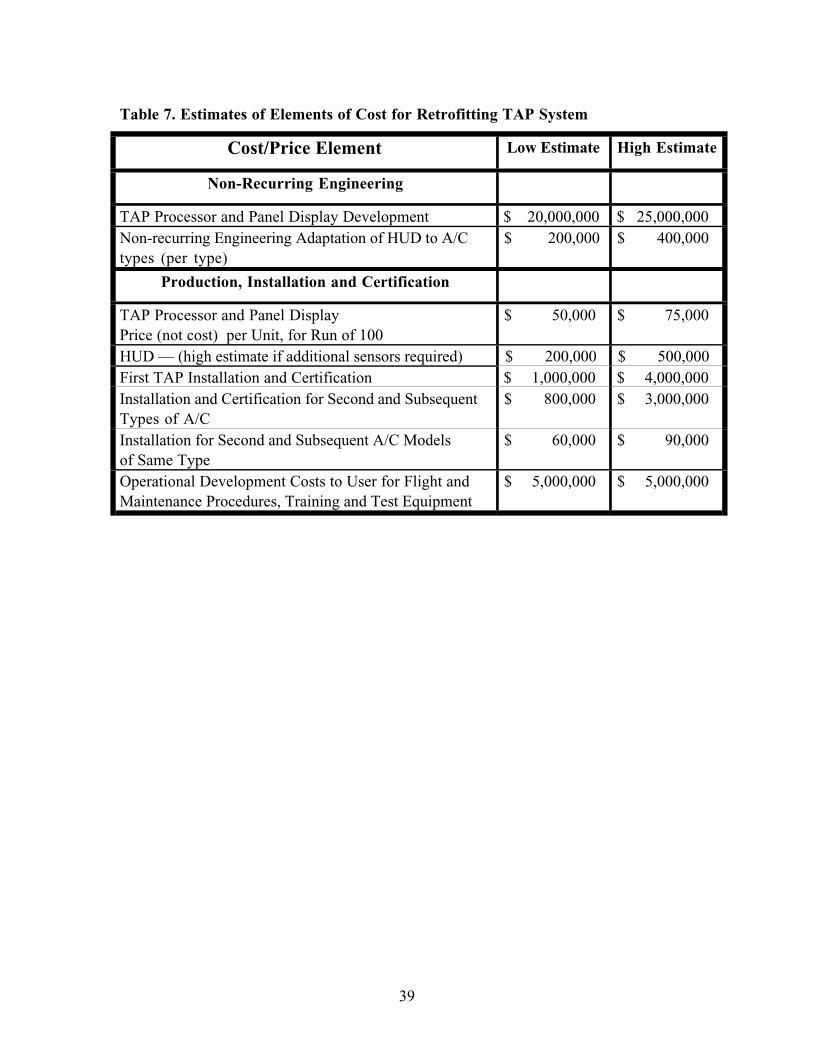
39
Table 7. Estimates of Elements of Cost for Retrofitting TAP System
Cost/Price Element Low Estimate High Estimate
Non-Recurring Engineering
TAP Processor and Panel Display Development $ 20,000,000 $ 25,000,000
Non-recurring Engineering Adaptation of HUD to A/C
types (per type)
$ 200,000 $ 400,000
Production, Installation and Certification
TAP Processor and Panel Display
Price (not cost) per Unit, for Run of 100
$ 50,000 $ 75,000
HUD — (high estimate if additional sensors required) $ 200,000 $ 500,000
First TAP Installation and Certification $ 1,000,000 $ 4,000,000
Installation and Certification for Second and Subsequent
Types of A/C
$ 800,000 $ 3,000,000
Installation for Second and Subsequent A/C Models
of Same Type
$ 60,000 $ 90,000
Operational Development Costs to User for Flight and
Maintenance Procedures, Training and Test Equipment
$ 5,000,000 $ 5,000,000
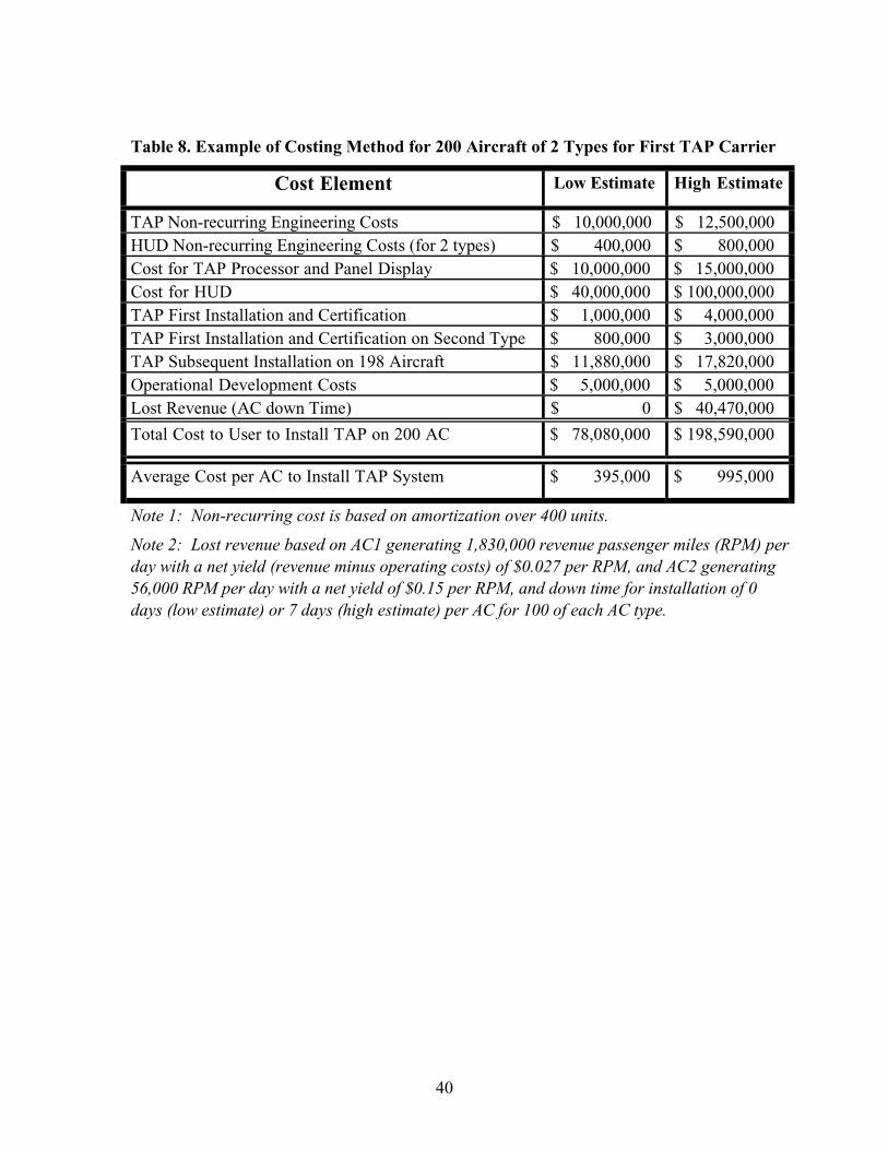
40
Table 8. Example of Costing Method for 200 Aircraft of 2 Types for First TAP Carrier
Cost Element Low Estimate High Estimate
TAP Non-recurring Engineering Costs $ 10,000,000 $ 12,500,000
HUD Non-recurring Engineering Costs (for 2 types) $ 400,000 $ 800,000
Cost for TAP Processor and Panel Display $ 10,000,000 $ 15,000,000
Cost for HUD $ 40,000,000 $ 100,000,000
TAP First Installation and Certification $ 1,000,000 $ 4,000,000
TAP First Installation and Certification on Second Type $ 800,000 $ 3,000,000
TAP Subsequent Installation on 198 Aircraft $ 11,880,000 $ 17,820,000
Operational Development Costs $ 5,000,000 $ 5,000,000
Lost Revenue (AC down Time) $ 0 $ 40,470,000
Total Cost to User to Install TAP on 200 AC $ 78,080,000 $ 198,590,000
Average Cost per AC to Install TAP System $ 395,000 $ 995,000
Note 1: Non-recurring cost is based on amortization over 400 units.
Note 2: Lost revenue based on AC1 generating 1,830,000 revenue passenger miles (RPM) perday with a net yield (revenue minus operating costs) of $0.027 per RPM, and AC2 generating56,000 RPM per day with a net yield of $0.15 per RPM, and down time for installation of 0days (low estimate) or 7 days (high estimate) per AC for 100 of each AC type.
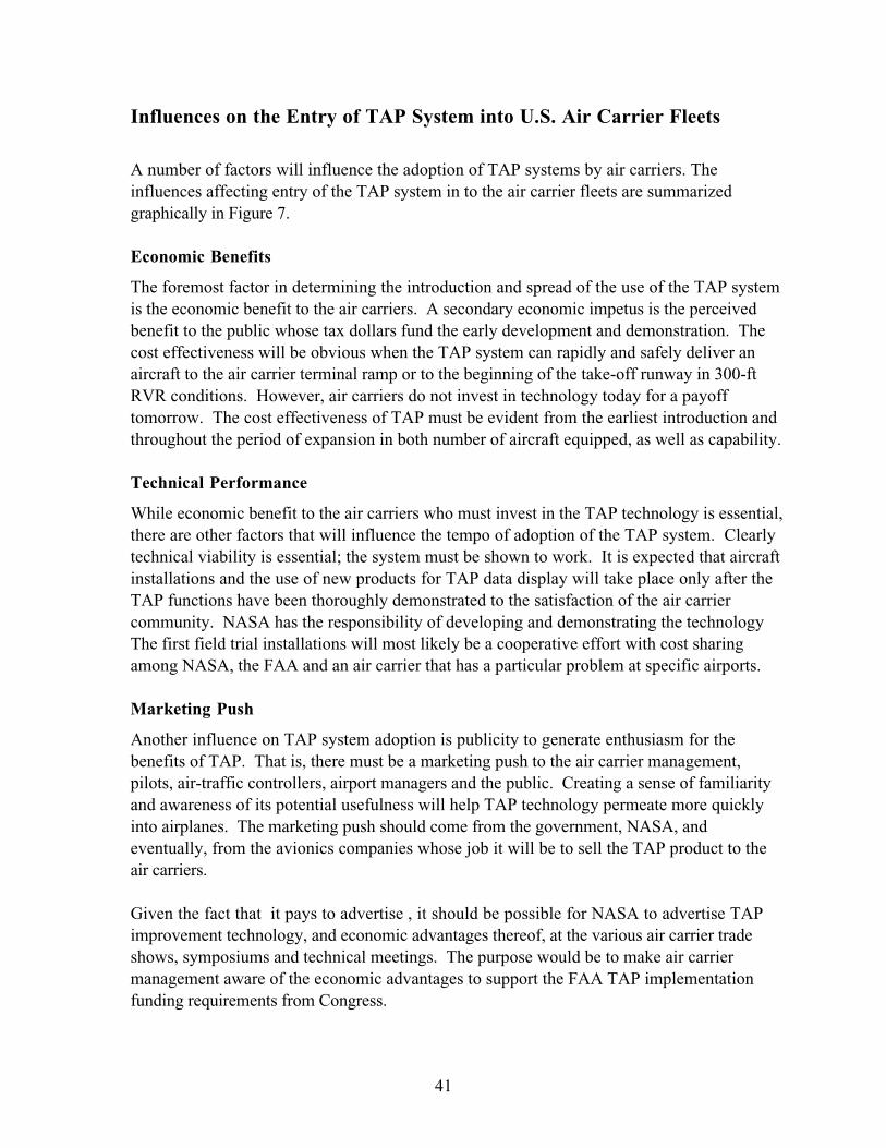
41
Influences on the Entry of TAP System into U.S. Air Carrier Fleets
A number of factors will influence the adoption of TAP systems by air carriers. The
influences affecting entry of the TAP system in to the air carrier fleets are summarized
graphically in Figure 7.
Economic Benefits
The foremost factor in determining the introduction and spread of the use of the TAP system
is the economic benefit to the air carriers. A secondary economic impetus is the perceived
benefit to the public whose tax dollars fund the early development and demonstration. The
cost effectiveness will be obvious when the TAP system can rapidly and safely deliver an
aircraft to the air carrier terminal ramp or to the beginning of the take-off runway in 300-ft
RVR conditions. However, air carriers do not invest in technology today for a payoff
tomorrow. The cost effectiveness of TAP must be evident from the earliest introduction and
throughout the period of expansion in both number of aircraft equipped, as well as capability.
Technical Performance
While economic benefit to the air carriers who must invest in the TAP technology is essential,
there are other factors that will influence the tempo of adoption of the TAP system. Clearly
technical viability is essential; the system must be shown to work. It is expected that aircraft
installations and the use of new products for TAP data display will take place only after the
TAP functions have been thoroughly demonstrated to the satisfaction of the air carrier
community. NASA has the responsibility of developing and demonstrating the technology
The first field trial installations will most likely be a cooperative effort with cost sharing
among NASA, the FAA and an air carrier that has a particular problem at specific airports.
Marketing Push
Another influence on TAP system adoption is publicity to generate enthusiasm for the
benefits of TAP. That is, there must be a marketing push to the air carrier management,
pilots, air-traffic controllers, airport managers and the public. Creating a sense of familiarity
and awareness of its potential usefulness will help TAP technology permeate more quickly
into airplanes. The marketing push should come from the government, NASA, and
eventually, from the avionics companies whose job it will be to sell the TAP product to the
air carriers.
Given the fact that it pays to advertise , it should be possible for NASA to advertise TAP
improvement technology, and economic advantages thereof, at the various air carrier trade
shows, symposiums and technical meetings. The purpose would be to make air carrier
management aware of the economic advantages to support the FAA TAP implementation
funding requirements from Congress.

42
During discussions with air carrier personnel related to gathering information for this report,
it was obvious that very few of the air carrier operations management staff had ever heard of
the FAA s TAP program, or its objectives and the part that NASA is playing in the program
development. However, after a few brief words, especially with air carrier pilots, it was
applauded as a very necessary and good idea. Preparing for acceptance of the TAP system
should not be a difficult marketing exercise provided it is done in a timely manner.
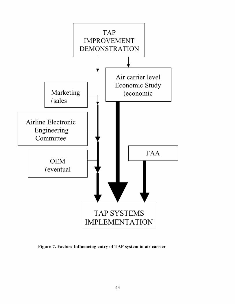
43
TAP SYSTEMS
IMPLEMENTATION
OEM
(eventual
Airline Electronic
Engineering
Committee
Marketing
(sales
Air carrier level
Economic Study
(economic
TAP
IMPROVEMENT
DEMONSTRATION
FAA
Figure 7. Factors Influencing entry of TAP system in air carrier
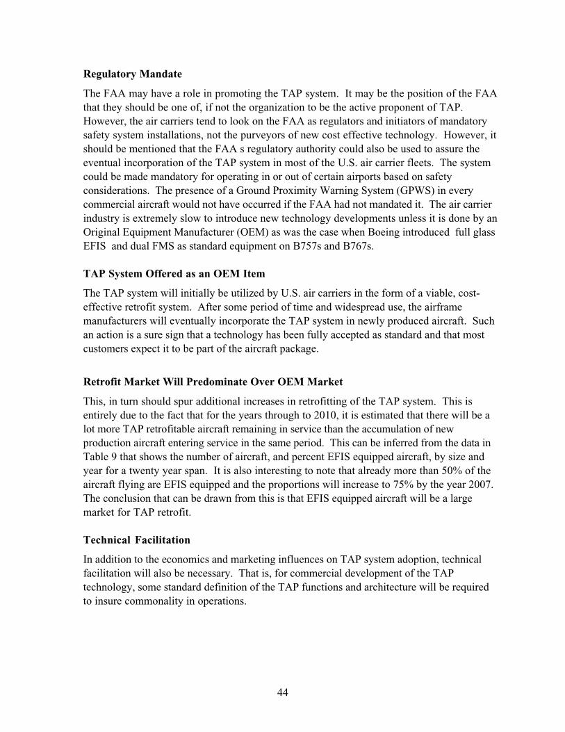
44
Regulatory Mandate
The FAA may have a role in promoting the TAP system. It may be the position of the FAA
that they should be one of, if not the organization to be the active proponent of TAP.
However, the air carriers tend to look on the FAA as regulators and initiators of mandatory
safety system installations, not the purveyors of new cost effective technology. However, it
should be mentioned that the FAA s regulatory authority could also be used to assure the
eventual incorporation of the TAP system in most of the U.S. air carrier fleets. The system
could be made mandatory for operating in or out of certain airports based on safety
considerations. The presence of a Ground Proximity Warning System (GPWS) in every
commercial aircraft would not have occurred if the FAA had not mandated it. The air carrier
industry is extremely slow to introduce new technology developments unless it is done by an
Original Equipment Manufacturer (OEM) as was the case when Boeing introduced full glass
EFIS and dual FMS as standard equipment on B757s and B767s.
TAP System Offered as an OEM Item
The TAP system will initially be utilized by U.S. air carriers in the form of a viable, cost-
effective retrofit system. After some period of time and widespread use, the airframe
manufacturers will eventually incorporate the TAP system in newly produced aircraft. Such
an action is a sure sign that a technology has been fully accepted as standard and that most
customers expect it to be part of the aircraft package.
Retrofit Market Will Predominate Over OEM Market
This, in turn should spur additional increases in retrofitting of the TAP system. This is
entirely due to the fact that for the years through to 2010, it is estimated that there will be a
lot more TAP retrofitable aircraft remaining in service than the accumulation of new
production aircraft entering service in the same period. This can be inferred from the data in
Table 9 that shows the number of aircraft, and percent EFIS equipped aircraft, by size and
year for a twenty year span. It is also interesting to note that already more than 50% of the
aircraft flying are EFIS equipped and the proportions will increase to 75% by the year 2007.
The conclusion that can be drawn from this is that EFIS equipped aircraft will be a large
market for TAP retrofit.
Technical Facilitation
In addition to the economics and marketing influences on TAP system adoption, technical
facilitation will also be necessary. That is, for commercial development of the TAP
technology, some standard definition of the TAP functions and architecture will be required
to insure commonality in operations.
45
Table 9. Number of Aircraft, and Percent with EFIS, by Size and Yearyear 1997 1998 1999 2000 2001 2002 2003 2004 2005 2006 2007 2008 2009 2010 2011 2012 2013 2014 2015 2016 2017
World-wide Jets
Single aisle50-90 615 681 748 814 880 947 1013 1079 1145 1212 1278 1344 1411 1477 1543 1610 1676 1742 1808 1875 1941
91-120 2897 2933 2968 3004 3039 3075 3110 3146 3181 3217 3253 3288 3324 3359 3395 3430 3466 3501 3537 3572 3608
121-170 4258 4467 4677 4886 5096 5305 5514 5724 5933 6143 6352 6561 6771 6980 7190 7399 7608 7818 8027 8237 8446
171-240 1213 1354 1496 1637 1779 1920 2062 2203 2345 2486 2628 2769 2910 3052 3193 3335 3476 3618 3759 3901 4042
Twin aisle230-310 1273 1373 1473 1574 1674 1774 1874 1974 2075 2175 2275 2375 2475 2576 2676 2776 2876 2976 3077 3177 3277
311-399 1007 1115 1224 1332 1440 1548 1657 1765 1873 1981 2090 2198 2306 2414 2523 2631 2739 2847 2956 3064 3172
>400 1016 1051 1086 1120 1155 1190 1225 1260 1294 1329 1364 1399 1434 1468 1503 1538 1573 1608 1642 1677 1712
total jets 12,279 12,975 13,671 14,367 15,063 15,759 16,455 17,151 17,847 18,543 19,239 19,934 20,630 21,326 22,022 22,718 23,414 24,110 24,806 25,502 26,198
EFIS penetration %
Single aisle50-90 45 48 50 53 56 59 61 64 67 69 72 75 77 80 83 86 88 91 94 96 99
91-120 45 48 50 53 56 59 61 64 67 69 72 75 77 80 83 86 88 91 94 96 99
121-170 40 43 46 49 52 55 58 61 64 67 70 72 75 78 81 84 87 90 93 96 99
171-240 65 67 68 70 72 74 75 77 79 80 82 84 85 87 89 91 92 94 96 97 99
Twin aisle230-310 55 57 59 62 64 66 68 70 73 75 77 79 81 84 86 88 90 92 95 97 99
311-399 60 62 64 66 68 70 72 74 76 78 80 81 83 85 87 89 91 93 95 97 99
>400 65 67 68 70 72 74 75 77 79 80 82 84 85 87 89 91 92 94 96 97 99
World-wide EFIS a/c
Single aisle50-90 277 325 377 432 491 554 620 690 763 840 920 1004 1092 1183 1278 1376 1478 1584 1693 1805 1922
91-120 1304 1399 1496 1595 1696 1799 1904 2010 2119 2229 2342 2456 2572 2691 2811 2933 3057 3183 3311 3440 3572
121-170 1703 1919 2147 2387 2640 2904 3182 3471 3774 4088 4415 4754 5105 5469 5845 6234 6635 7048 7473 7911 8362
171-240 788 903 1023 1148 1277 1411 1550 1694 1843 1996 2155 2318 2485 2658 2836 3018 3205 3397 3594 3795 4002
Twin aisle230-310 700 785 875 969 1068 1171 1278 1390 1506 1627 1752 1881 2015 2153 2296 2443 2594 2750 2910 3075 3244
311-399 604 691 782 877 976 1080 1188 1300 1416 1536 1661 1790 1923 2061 2202 2348 2498 2652 2811 2973 3140
>400 660 701 743 785 829 875 921 969 1017 1067 1118 1171 1224 1279 1335 1392 1450 1510 1570 1632 1695
Total EFIS a/c 6,037 6,723 7,442 8,194 8,977 9,794 10,643 11,524 12,438 13,384 14,363 15,374 16,417 17,494 18,602 19,743 20,917 22,123 23,362 24,633 25,936
EFIS SUMMARY
World-wide 6,037 6,723 7,442 8,194 8,977 9,794 10,643 11,524 12,438 13,384 14,363 15,374 16,417 17,494 18,602 19,743 20,917 22,123 23,362 24,633 25,936
North America % 48.0% 47.5% 47.0% 46.5% 46.0% 45.5% 45.0% 44.5% 44.0% 43.5% 43.0% 42.5% 42.0% 41.5% 41.0% 40.5% 40.0% 39.5% 39.0% 38.5% 38.0%
North America 2,898 3,194 3,498 3,810 4,130 4,456 4,789 5,128 5,473 5,822 6,176 6,534 6,895 7,260 7,627 7,996 8,367 8,739 9,111 9,484 9,856
year 1997 1998 1999 2000 2001 2002 2003 2004 2005 2006 2007 2008 2009 2010 2011 2012 2013 2014 2015 2016 2017
Data courtesy of Flight Dynamics, 1998; compiled by George Kanellis based on unpublished, internal marketing report using data supplied
by the Boeing Aircraft Company and Airbus Industries.
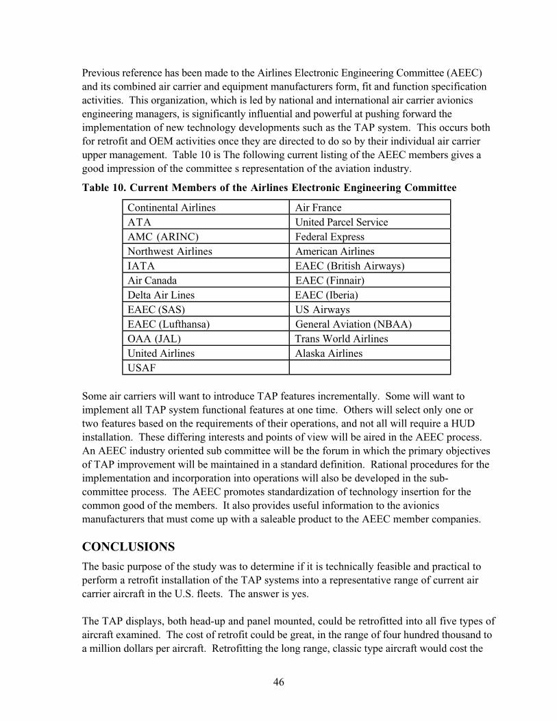
46
Previous reference has been made to the Airlines Electronic Engineering Committee (AEEC)
and its combined air carrier and equipment manufacturers form, fit and function specification
activities. This organization, which is led by national and international air carrier avionics
engineering managers, is significantly influential and powerful at pushing forward the
implementation of new technology developments such as the TAP system. This occurs both
for retrofit and OEM activities once they are directed to do so by their individual air carrier
upper management. Table 10 is The following current listing of the AEEC members gives a
good impression of the committee s representation of the aviation industry.
Table 10. Current Members of the Airlines Electronic Engineering Committee
Continental Airlines Air France
ATA United Parcel Service
AMC (ARINC) Federal Express
Northwest Airlines American Airlines
IATA EAEC (British Airways)
Air Canada EAEC (Finnair)
Delta Air Lines EAEC (Iberia)
EAEC (SAS) US Airways
EAEC (Lufthansa) General Aviation (NBAA)
OAA (JAL) Trans World Airlines
United Airlines Alaska Airlines
USAF
Some air carriers will want to introduce TAP features incrementally. Some will want to
implement all TAP system functional features at one time. Others will select only one or
two features based on the requirements of their operations, and not all will require a HUD
installation. These differing interests and points of view will be aired in the AEEC process.
An AEEC industry oriented sub committee will be the forum in which the primary objectives
of TAP improvement will be maintained in a standard definition. Rational procedures for the
implementation and incorporation into operations will also be developed in the sub-
committee process. The AEEC promotes standardization of technology insertion for the
common good of the members. It also provides useful information to the avionics
manufacturers that must come up with a saleable product to the AEEC member companies.
CONCLUSIONS
The basic purpose of the study was to determine if it is technically feasible and practical to
perform a retrofit installation of the TAP systems into a representative range of current air
carrier aircraft in the U.S. fleets. The answer is yes.
The TAP displays, both head-up and panel mounted, could be retrofitted into all five types of
aircraft examined. The cost of retrofit could be great, in the range of four hundred thousand to
a million dollars per aircraft. Retrofitting the long range, classic type aircraft would cost the
47
most. Perhaps surprisingly, retrofitting the newest, glass-cockpit type aircraft, would likely
be the next most expensive. The work and costs involve physical installation, requiring (in
some cases) movement of existing equipment, software additions and modifications, and re-
certification of the software. This last element can be very expensive, especially for the glass
cockpit configurations.
Providing the TAP system capability for extended range, classic aircraft such as the B747-
200/300 and the DC-10 would require a complete stand-alone TAP system. The existing on-
board equipment is simply inadequate to provide the sensor inputs, data communications,
data processing, and symbol generation capabilities needed to support the TAP HUD and
panel mounted, or Head Down Display . On the other hand, it appears feasible for aircraft
equipped with a full EFIS display suite to use the existing sensor, communications, processor
and symbol generating facilities to support the TAP system and displays. However, while
potentially feasible, it may not be economically practical because of the cost of the required
hardware and software modifications. Not only must new capability be added, but it must
also be demonstrated beyond any doubt that the TAP modifications do not interfere with the
pre-existing functions. In other words, even for aircraft with a full EFIS display suite, the
most viable alternative for installing a TAP display system may be a stand-alone system that
interacts minimally with existing systems by way of only sharing one or more display
surfaces.
A significant cost of new-design or retrofitted avionics is attributable to having to meet
certification requirements of the FAA for air transport operations in the U.S. National Air
Space.
The retrofit approach requiring the least effort appears to be incorporating the TAP system
and displays as a stand-alone add-on package with minimal change to current drive
electronics, computers, and software. The alternative is to modify existing systems to
assimilate the TAP functions. For the complete TAP display suite this is likely to be more
costly than the stand-alone alternative. However, it could be a more cost-effective approach
if only one or two of the TAP system and displays were retrofitted.
It is important to recognize that as the TAP program evolves and migrates to implementation,
the four different TAP functions and displays (CTAS/FMS, AILS, ROTO and T-NASA),
may not have equal appeal or be operationally justifiable by the air carrier.
Achieving the TAP objective of increased productivity depends on several factors, of which
technical feasibility is merely the first requisite. Ultimately, it will be the air carriers who
determine the success of the TAP program. The most potent influence on adoption of TAP
technology by an air carrier is the expected accrual of economic benefits. Without recovery of
costs and increased profit within a relatively short time, no additional systems would be
installed on aircraft, unless mandated by the FAA. This latter alternative is unlikely in the
case of TAP equipment. An additional influence on the incorporation of TAP technology in
48
aircraft would be an agreement on a cooperative, phased, technical implementation plan by
the Airline Electronic Engineering Committee.
Few innovations succeed without a sales push. NASA, aided by the avionics equipment
manufacturers, should be prepared to publicize TAP capabilities and expected benefits. The
TAP aircraft systems culminating success will be when it is included, first as an option, and
then as standard by aircraft manufacturers. This is not likely to occur for some time.
Retrofitting will be more common in the early years simply because manufacturers will be
unwilling to risk the development and certification costs to incorporate a technology in new
aircraft until it is well established and customers demand it. In the early stages, it will be the
air carriers that will bear the cost of retrofit and certification.
RECOMMENDATIONS
Technical
Using a generic, self-contained, common TAP Processor Unit, with a centrally mounted
display, should be considered as the basic approach for retrofitting current aircraft. For EFIS
equipped aircraft with full glass cockpits, an existing display may be used.
NASA should engage in a follow-on phase to this study to develop generic designs for TAP
aircraft equipment, and installations for non glass as well as glass cockpits.
At an early opportunity, NASA should install a full suite of the TAP system in its B757 for
demonstration to any potential air carrier user.
In light of the current size of cockpit displays as given in Table 5, NASA should determine
the acceptable envelope of display size, aspect-ratio, and resolvable detail for the panel
mounted display.
Programmatic
The utilization of the TAP system by air carriers is a definite economic issue that needs to be
addressed. A thorough economic study, oriented toward the cost-benefits to air carriers,
should be conducted as soon as possible to determine the individual and collective worth of
the TAP system to air carriers. The study could be sponsored by NASA, but should be
conducted by economics experts knowledgeable in the area of U.S. air carrier operations. The
scope should include type of carrier, types of aircraft used and airports used. The results of
this study would also indicate which segment of air carrier operations would gain the most
advantage from TAP improvement.
Again, at an early opportunity, NASA should begin informational marketing to air carrier
upper management. This should be directed at potential TAP system users, and include air
carrier executive meetings hosted by ATA or IATA. Also, general advertising on the
49
progress of the TAP program and its intrinsic benefits should be promoted through air carrier
oriented magazine articles. Technical papers should be delivered at symposiums and annual
organizational meetings of the ATA, IATA, and ICAO, and at the air carriers AEEC yearly
conference.
NASA should solicit the views of foreign air carriers to establish their interest and concerns in
using the TAP system for their scheduled operations into specific U.S. airports.
The form, fit and function of the equipment should be in accordance with the air carriers
AEEC procedures, based on a system specification controlled by the FAA in conjunction with
NASA.
A draft TAP system airworthiness and operational certification plan should be developed at
an early opportunity. TAP certification in the lower approach, landing and roll-out realms is
likely to require almost the same effort as re-certification of the whole landing system. The
certification plan should cover the ground elements as well as the aircraft elements referred to
in this report.

50
REFERENCES
Hooey, B.L., Schwirzke, M.F.J., McCauley, M.E., Purcell, K.P., and Andre, A.D. (1998)
Initial Identification of Procedural Issues for the Future Deployment of Terminal Area
Productivity (TAP) Technologies. (NASA Contractor Report). Moffett Field, CA: NASA
Ames Research Center.
51
APPENDIX A - DESCRIPTIONS OF TAP SYSTEM TECHNOLOGIESTERMINAL AREA PRODUCTIVITY (TAP) DISPLAYS
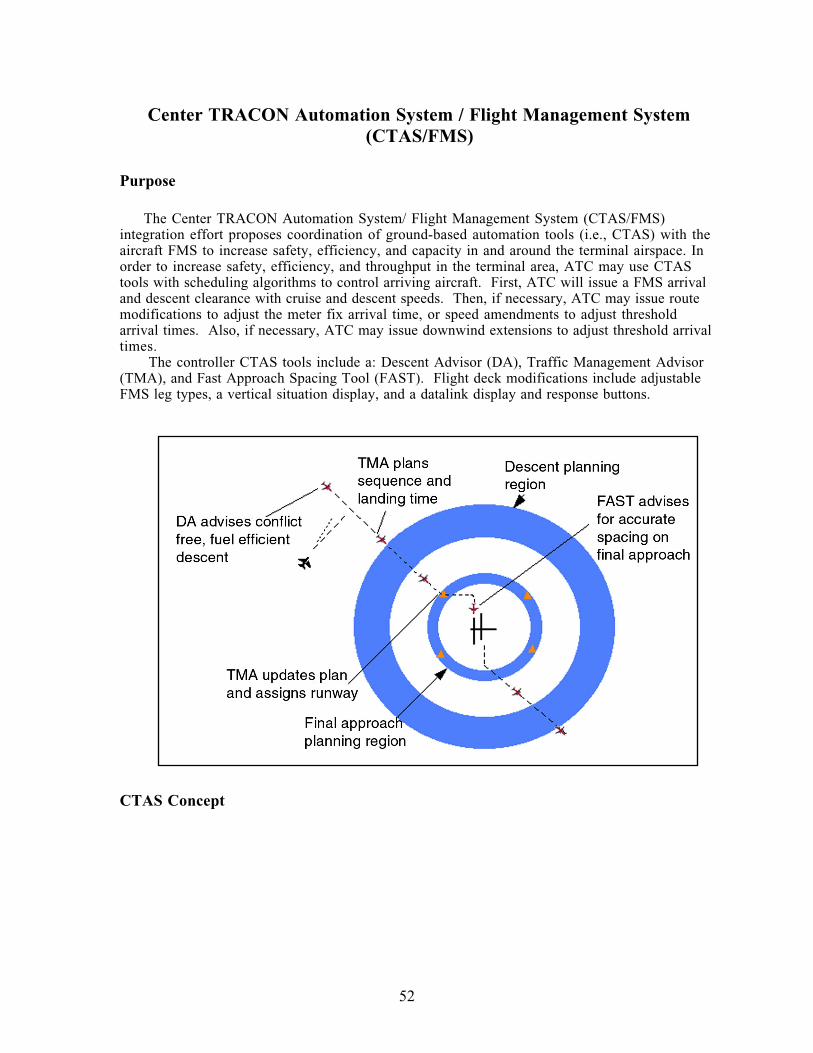
52
Center TRACON Automation System / Flight Management System(CTAS/FMS)
Purpose
The Center TRACON Automation System/ Flight Management System (CTAS/FMS)
integration effort proposes coordination of ground-based automation tools (i.e., CTAS) with the
aircraft FMS to increase safety, efficiency, and capacity in and around the terminal airspace. In
order to increase safety, efficiency, and throughput in the terminal area, ATC may use CTAS
tools with scheduling algorithms to control arriving aircraft. First, ATC will issue a FMS arrival
and descent clearance with cruise and descent speeds. Then, if necessary, ATC may issue route
modifications to adjust the meter fix arrival time, or speed amendments to adjust threshold
arrival times. Also, if necessary, ATC may issue downwind extensions to adjust threshold arrival
times.
The controller CTAS tools include a: Descent Advisor (DA), Traffic Management Advisor
(TMA), and Fast Approach Spacing Tool (FAST). Flight deck modifications include adjustable
FMS leg types, a vertical situation display, and a datalink display and response buttons.
CTAS Concept
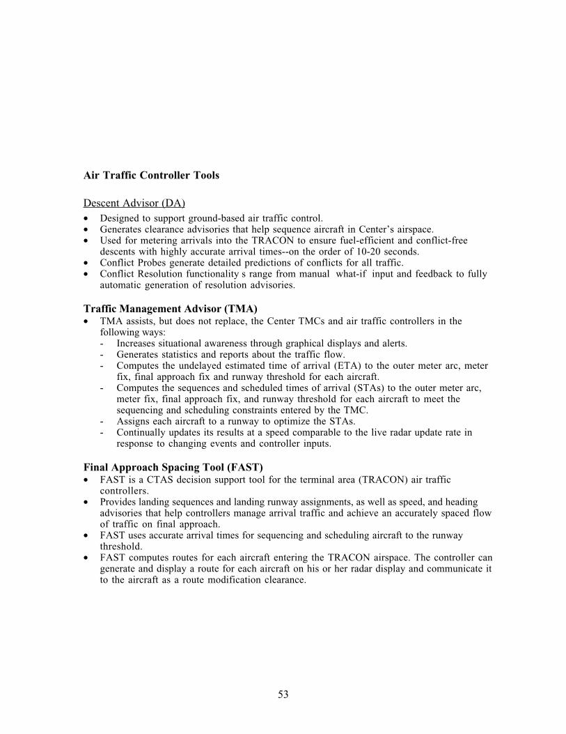
53
Air Traffic Controller Tools
Descent Advisor (DA)
• Designed to support ground-based air traffic control.
• Generates clearance advisories that help sequence aircraft in Center’s airspace.
• Used for metering arrivals into the TRACON to ensure fuel-efficient and conflict-free
descents with highly accurate arrival times--on the order of 10-20 seconds.
• Conflict Probes generate detailed predictions of conflicts for all traffic.
• Conflict Resolution functionality s range from manual what-if input and feedback to fully
automatic generation of resolution advisories.
Traffic Management Advisor (TMA)• TMA assists, but does not replace, the Center TMCs and air traffic controllers in the
following ways:
- Increases situational awareness through graphical displays and alerts.
- Generates statistics and reports about the traffic flow.
- Computes the undelayed estimated time of arrival (ETA) to the outer meter arc, meter
fix, final approach fix and runway threshold for each aircraft.
- Computes the sequences and scheduled times of arrival (STAs) to the outer meter arc,
meter fix, final approach fix, and runway threshold for each aircraft to meet the
sequencing and scheduling constraints entered by the TMC.
- Assigns each aircraft to a runway to optimize the STAs.
- Continually updates its results at a speed comparable to the live radar update rate in
response to changing events and controller inputs.
Final Approach Spacing Tool (FAST)• FAST is a CTAS decision support tool for the terminal area (TRACON) air traffic
controllers.
• Provides landing sequences and landing runway assignments, as well as speed, and heading
advisories that help controllers manage arrival traffic and achieve an accurately spaced flow
of traffic on final approach.
• FAST uses accurate arrival times for sequencing and scheduling aircraft to the runway
threshold.
• FAST computes routes for each aircraft entering the TRACON airspace. The controller can
generate and display a route for each aircraft on his or her radar display and communicate it
to the aircraft as a route modification clearance.
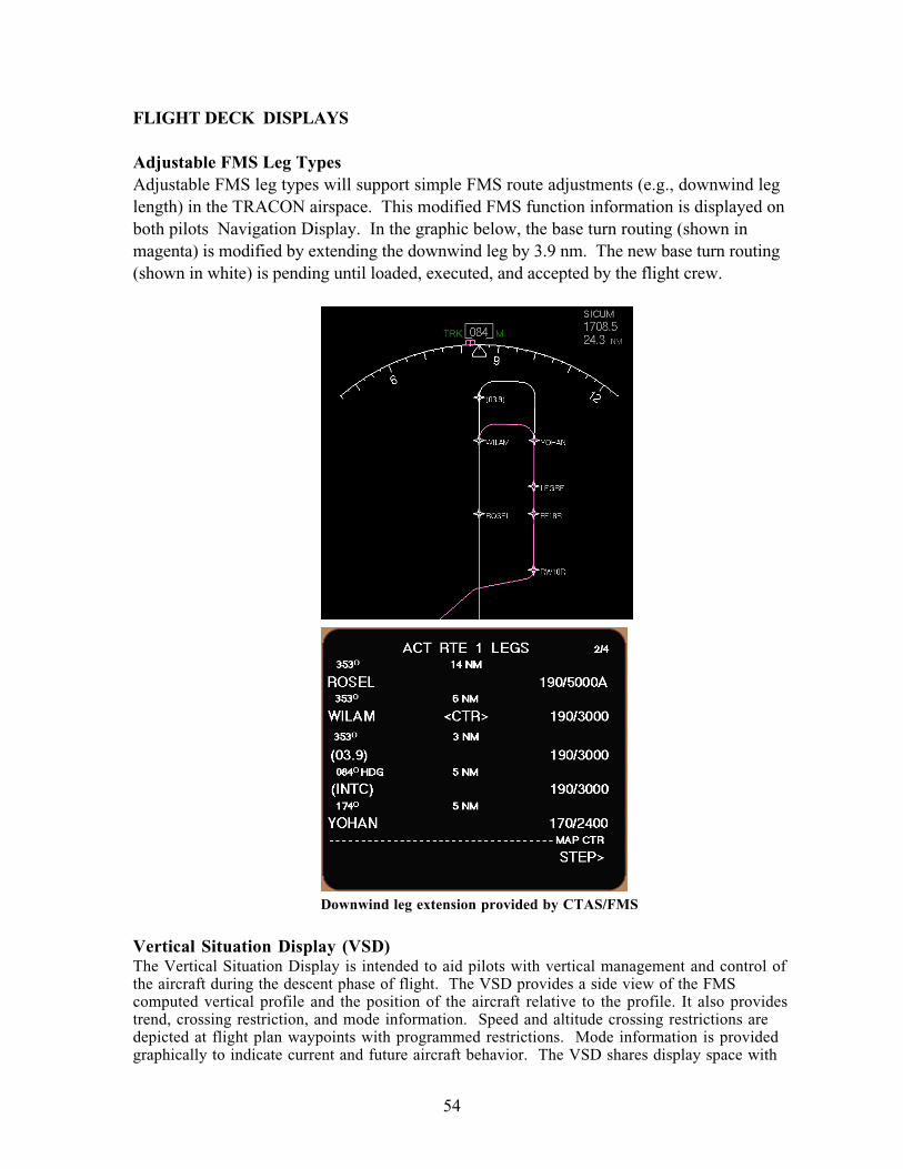
54
FLIGHT DECK DISPLAYS
Adjustable FMS Leg TypesAdjustable FMS leg types will support simple FMS route adjustments (e.g., downwind leg
length) in the TRACON airspace. This modified FMS function information is displayed on
both pilots Navigation Display. In the graphic below, the base turn routing (shown in
magenta) is modified by extending the downwind leg by 3.9 nm. The new base turn routing
(shown in white) is pending until loaded, executed, and accepted by the flight crew.
Downwind leg extension provided by CTAS/FMS
Vertical Situation Display (VSD)The Vertical Situation Display is intended to aid pilots with vertical management and control of
the aircraft during the descent phase of flight. The VSD provides a side view of the FMS
computed vertical profile and the position of the aircraft relative to the profile. It also provides
trend, crossing restriction, and mode information. Speed and altitude crossing restrictions are
depicted at flight plan waypoints with programmed restrictions. Mode information is provided
graphically to indicate current and future aircraft behavior. The VSD shares display space with
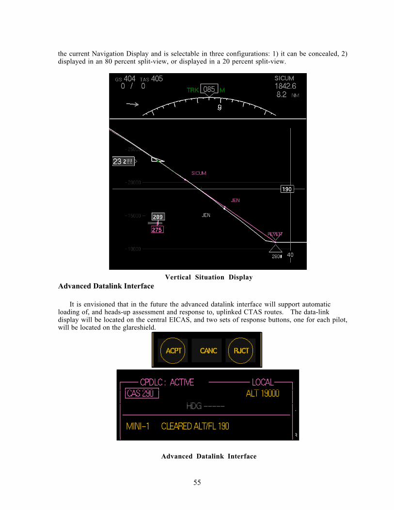
55
the current Navigation Display and is selectable in three configurations: 1) it can be concealed, 2)
displayed in an 80 percent split-view, or displayed in a 20 percent split-view.
Vertical Situation DisplayAdvanced Datalink Interface
It is envisioned that in the future the advanced datalink interface will support automatic
loading of, and heads-up assessment and response to, uplinked CTAS routes. The data-link
display will be located on the central EICAS, and two sets of response buttons, one for each pilot,
will be located on the glareshield.
Advanced Datalink Interface
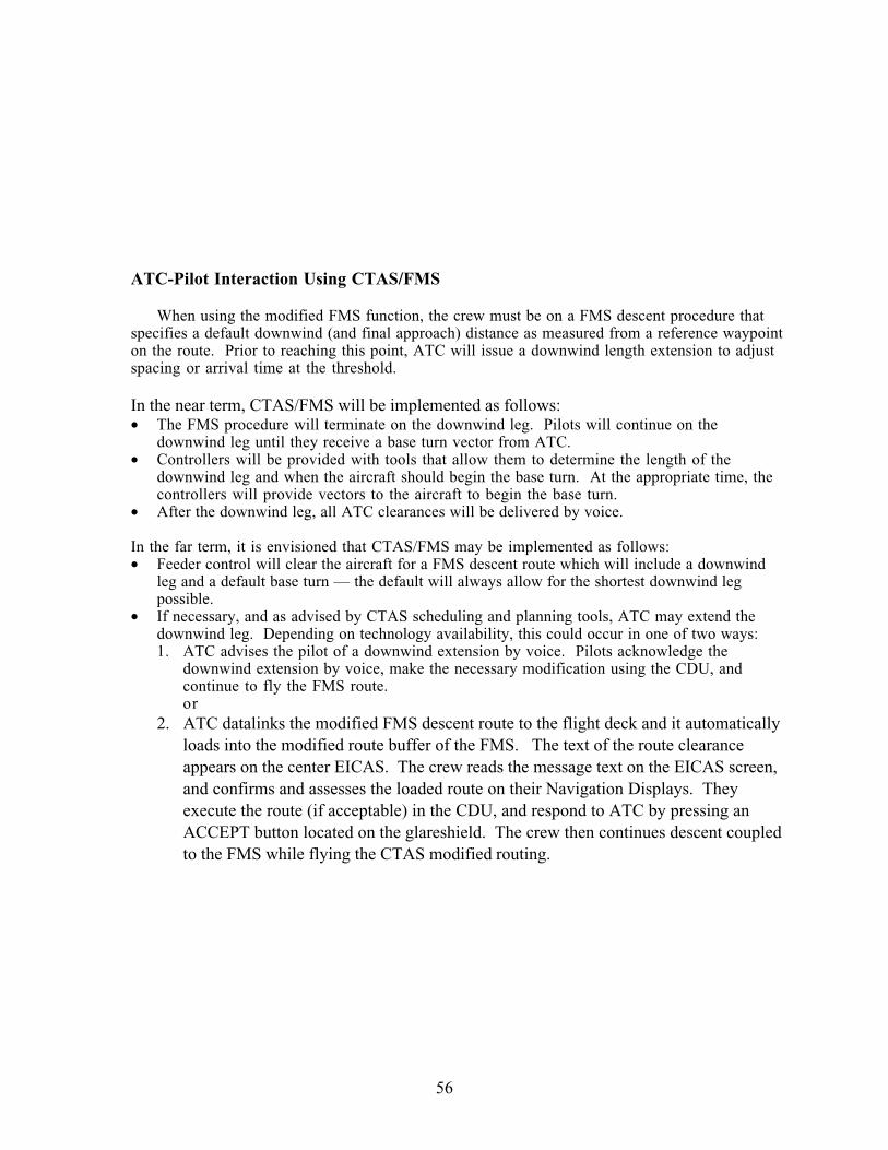
56
ATC-Pilot Interaction Using CTAS/FMS
When using the modified FMS function, the crew must be on a FMS descent procedure that
specifies a default downwind (and final approach) distance as measured from a reference waypoint
on the route. Prior to reaching this point, ATC will issue a downwind length extension to adjust
spacing or arrival time at the threshold.
In the near term, CTAS/FMS will be implemented as follows:
• The FMS procedure will terminate on the downwind leg. Pilots will continue on the
downwind leg until they receive a base turn vector from ATC.
• Controllers will be provided with tools that allow them to determine the length of the
downwind leg and when the aircraft should begin the base turn. At the appropriate time, the
controllers will provide vectors to the aircraft to begin the base turn.
• After the downwind leg, all ATC clearances will be delivered by voice.
In the far term, it is envisioned that CTAS/FMS may be implemented as follows:
• Feeder control will clear the aircraft for a FMS descent route which will include a downwind
leg and a default base turn — the default will always allow for the shortest downwind leg
possible.
• If necessary, and as advised by CTAS scheduling and planning tools, ATC may extend the
downwind leg. Depending on technology availability, this could occur in one of two ways:
1. ATC advises the pilot of a downwind extension by voice. Pilots acknowledge the
downwind extension by voice, make the necessary modification using the CDU, and
continue to fly the FMS route.
or
2. ATC datalinks the modified FMS descent route to the flight deck and it automatically
loads into the modified route buffer of the FMS. The text of the route clearance
appears on the center EICAS. The crew reads the message text on the EICAS screen,
and confirms and assesses the loaded route on their Navigation Displays. They
execute the route (if acceptable) in the CDU, and respond to ATC by pressing an
ACCEPT button located on the glareshield. The crew then continues descent coupled
to the FMS while flying the CTAS modified routing.
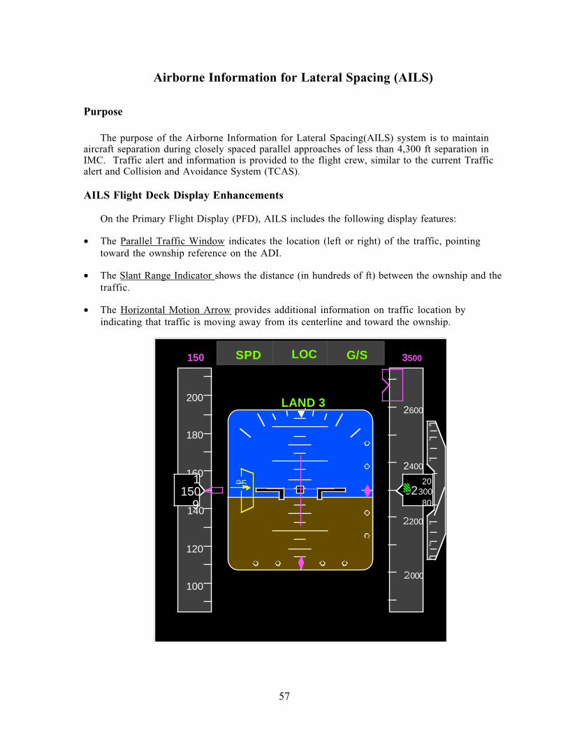
57
Airborne Information for Lateral Spacing (AILS)
Purpose
The purpose of the Airborne Information for Lateral Spacing(AILS) system is to maintain
aircraft separation during closely spaced parallel approaches of less than 4,300 ft separation in
IMC. Traffic alert and information is provided to the flight crew, similar to the current Traffic
alert and Collision and Avoidance System (TCAS).
AILS Flight Deck Display Enhancements
On the Primary Flight Display (PFD), AILS includes the following display features:
• The Parallel Traffic Window indicates the location (left or right) of the traffic, pointing
toward the ownship reference on the ADI.
• The Slant Range Indicator shows the distance (in hundreds of ft) between the ownship and the
traffic.
• The Horizontal Motion Arrow provides additional information on traffic location by
indicating that traffic is moving away from its centerline and toward the ownship.
160
2600
2000
02300
140
150
180
200
100
120
20
80
2400
9
1
6
2
1
1
2
6
2200
150 3500
LAND 3
LOC G/SSPD
25
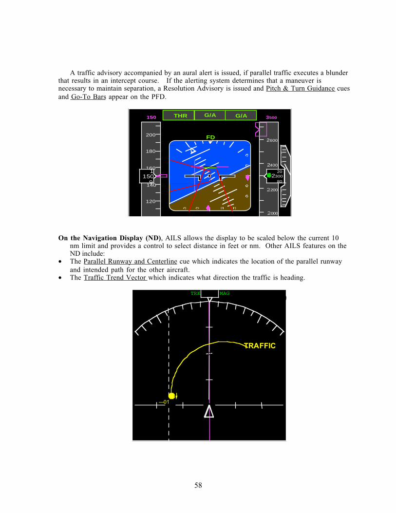
58
A traffic advisory accompanied by an aural alert is issued, if parallel traffic executes a blunder
that results in an intercept course. If the alerting system determines that a maneuver is
necessary to maintain separation, a Resolution Advisory is issued and Pitch & Turn Guidance cues
and Go-To Bars appear on the PFD.
160
2600
2000
02300
140
150
180
200
120
20
80
2400
9
1
6
2
1
1
2
6
2200
150 3500
FD
G/A G/ATHR
On the Navigation Display (ND), AILS allows the display to be scaled below the current 10
nm limit and provides a control to select distance in feet or nm. Other AILS features on the
ND include:
• The Parallel Runway and Centerline cue which indicates the location of the parallel runway
and intended path for the other aircraft.
• The Traffic Trend Vector which indicates what direction the traffic is heading.
3000 3000
GS157TAS157000¡/00
000TRK MAG
333
— 01
3000
00 00.0Z00.0NM
TRAFFIC
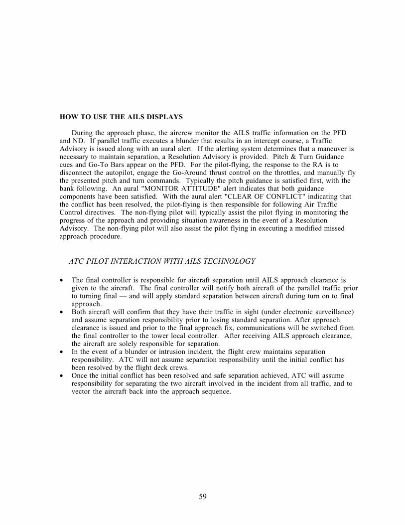
59
HOW TO USE THE AILS DISPLAYS
During the approach phase, the aircrew monitor the AILS traffic information on the PFD
and ND. If parallel traffic executes a blunder that results in an intercept course, a Traffic
Advisory is issued along with an aural alert. If the alerting system determines that a maneuver is
necessary to maintain separation, a Resolution Advisory is provided. Pitch & Turn Guidance
cues and Go-To Bars appear on the PFD. For the pilot-flying, the response to the RA is to
disconnect the autopilot, engage the Go-Around thrust control on the throttles, and manually fly
the presented pitch and turn commands. Typically the pitch guidance is satisfied first, with the
bank following. An aural "MONITOR ATTITUDE" alert indicates that both guidance
components have been satisfied. With the aural alert "CLEAR OF CONFLICT" indicating that
the conflict has been resolved, the pilot-flying is then responsible for following Air Traffic
Control directives. The non-flying pilot will typically assist the pilot flying in monitoring the
progress of the approach and providing situation awareness in the event of a Resolution
Advisory. The non-flying pilot will also assist the pilot flying in executing a modified missed
approach procedure.
ATC-PILOT INTERACTION WITH AILS TECHNOLOGY
• The final controller is responsible for aircraft separation until AILS approach clearance is
given to the aircraft. The final controller will notify both aircraft of the parallel traffic prior
to turning final — and will apply standard separation between aircraft during turn on to final
approach.
• Both aircraft will confirm that they have their traffic in sight (under electronic surveillance)
and assume separation responsibility prior to losing standard separation. After approach
clearance is issued and prior to the final approach fix, communications will be switched from
the final controller to the tower local controller. After receiving AILS approach clearance,
the aircraft are solely responsible for separation.
• In the event of a blunder or intrusion incident, the flight crew maintains separation
responsibility. ATC will not assume separation responsibility until the initial conflict has
been resolved by the flight deck crews.
• Once the initial conflict has been resolved and safe separation achieved, ATC will assume
responsibility for separating the two aircraft involved in the incident from all traffic, and to
vector the aircraft back into the approach sequence.
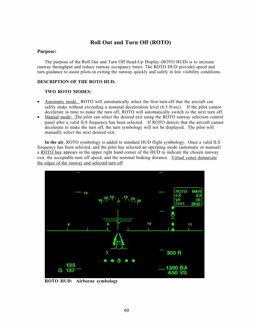
60
Roll Out and Turn Off (ROTO)
Purpose:
The purpose of the Roll Out and Turn Off Head-Up Display (ROTO HUD) is to increase
runway throughput and reduce runway occupancy times. The ROTO HUD provides speed and
turn guidance to assist pilots in exiting the runway quickly and safely in low visibility conditions.
DESCRIPTION OF THE ROTO HUD:
TWO ROTO MODES:
• Automatic mode: ROTO will automatically select the first turn-off that the aircraft can
safely make without exceeding a nominal deceleration level (6.5 ft/sec). If the pilot cannot
decelerate in time to make the turn off, ROTO will automatically switch to the next turn off.
• Manual mode: The pilot can select the desired exit using the ROTO runway selection control
panel after a valid ILS frequency has been selected. If ROTO detects that the aircraft cannot
decelerate to make the turn off, the turn symbology will not be displayed. The pilot will
manually select the next desired exit.
In the air, ROTO symbology is added to standard HUD flight symbology. Once a valid ILS
frequency has been selected, and the pilot has selected an operating mode (automatic or manual)
a ROTO box appears in the upper right hand corner of the HUD to indicate the chosen runway
exit, the acceptable turn off speed, and the nominal braking distance. Virtual cones demarcate
the edges of the runway and selected turn off.
ROTO HUD: Airborne symbology
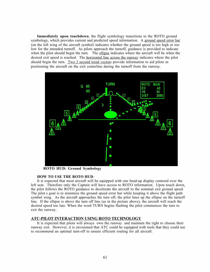
61
Immediately upon touchdown, the flight symbology transitions to the ROTO ground
symbology, which provides current and predicted speed information. A ground speed error bar
(on the left wing of the aircraft symbol) indicates whether the ground speed is too high or too
low for the intended turnoff. As pilots approach the turnoff, guidance is provided to indicate
when the pilot should begin the turn. The ellipse indicates where the aircraft will be when the
desired exit speed is reached. The horizontal line across the runway indicates where the pilot
should begin the turn. Two 2 second trend vectors provide information to aid pilots in
positioning the aircraft on the exit centerline during the turnoff from the runway.
ROTO HUD: Ground Symbology
HOW TO USE THE ROTO HUD:
It is expected that most aircraft will be equipped with one head-up display centered over the
left seat. Therefore only the Captain will have access to ROTO information. Upon touch down,
the pilot follows the ROTO guidance to decelerate the aircraft to the nominal exit ground speed.
The pilot s goal is to minimize the ground speed error bar while keeping it above the flight path
symbol wing. As the aircraft approaches the turn off, the pilot lines up the ellipse on the turnoff
line. If the ellipse is above the turn off line (as in the picture above), the aircraft will reach the
desired speed too late. When the word TURN begins flashing the pilot commences the turn to
exit the runway.
ATC-PILOT INTERACTION USING ROTO TECHNOLOGYIt is expected that pilots will always own the runway and maintain the right to choose their
runway exit. However, it is envisioned that ATC could be equipped with tools that they could use
to recommend an optimal turn-off to ensure efficient routing for all aircraft.
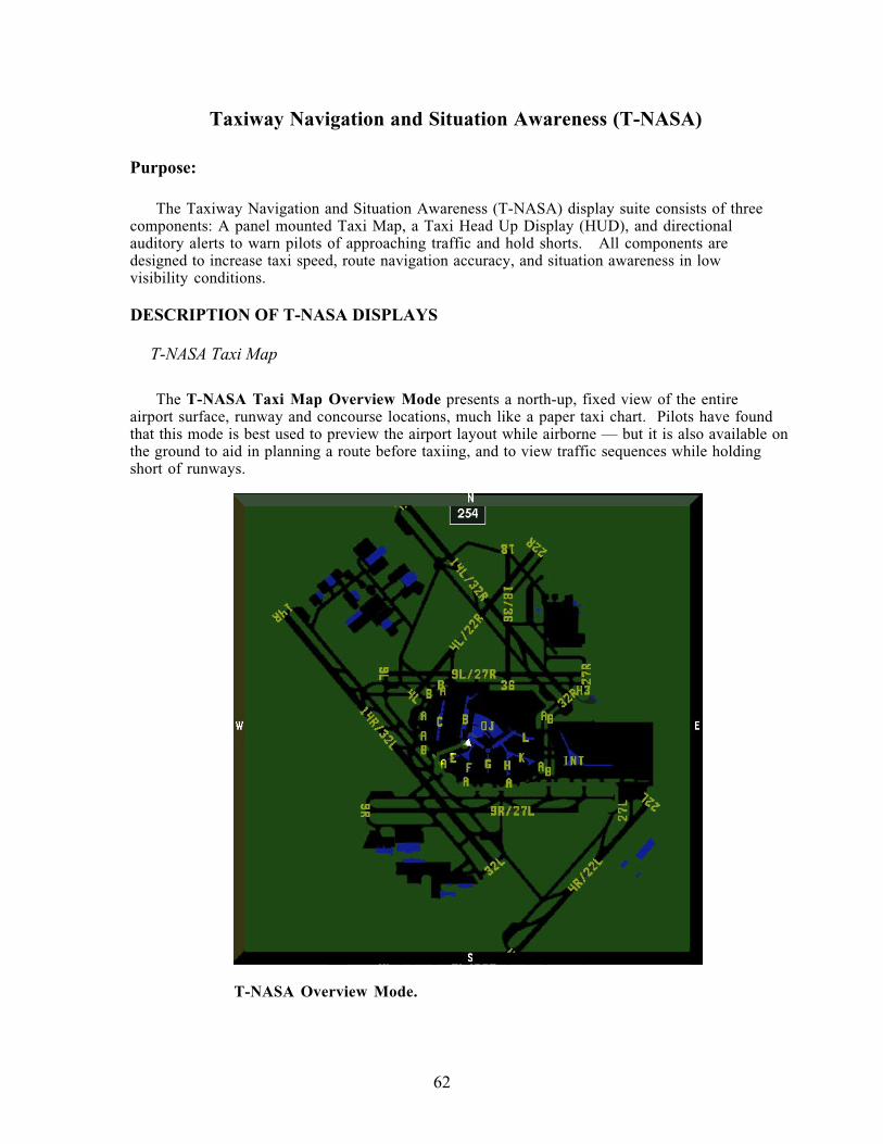
62
Taxiway Navigation and Situation Awareness (T-NASA)
Purpose:
The Taxiway Navigation and Situation Awareness (T-NASA) display suite consists of three
components: A panel mounted Taxi Map, a Taxi Head Up Display (HUD), and directional
auditory alerts to warn pilots of approaching traffic and hold shorts. All components are
designed to increase taxi speed, route navigation accuracy, and situation awareness in low
visibility conditions.
DESCRIPTION OF T-NASA DISPLAYS
T-NASA Taxi Map
The T-NASA Taxi Map Overview Mode presents a north-up, fixed view of the entire
airport surface, runway and concourse locations, much like a paper taxi chart. Pilots have found
that this mode is best used to preview the airport layout while airborne — but it is also available on
the ground to aid in planning a route before taxiing, and to view traffic sequences while holding
short of runways.
T-NASA Overview Mode.
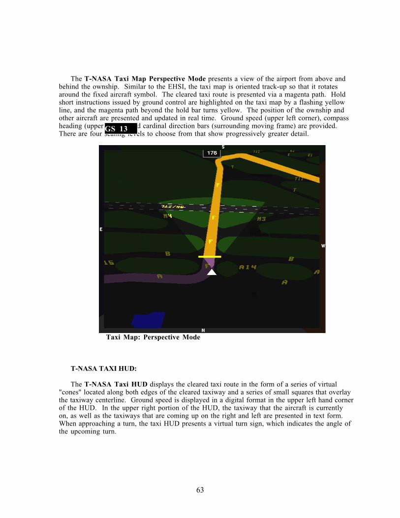
63
The T-NASA Taxi Map Perspective Mode presents a view of the airport from above and
behind the ownship. Similar to the EHSI, the taxi map is oriented track-up so that it rotates
around the fixed aircraft symbol. The cleared taxi route is presented via a magenta path. Hold
short instructions issued by ground control are highlighted on the taxi map by a flashing yellow
line, and the magenta path beyond the hold bar turns yellow. The position of the ownship and
other aircraft are presented and updated in real time. Ground speed (upper left corner), compass
heading (upper center), and cardinal direction bars (surrounding moving frame) are provided.
There are four scaling levels to choose from that show progressively greater detail.
Taxi Map: Perspective Mode
T-NASA TAXI HUD:
The T-NASA Taxi HUD displays the cleared taxi route in the form of a series of virtual
"cones" located along both edges of the cleared taxiway and a series of small squares that overlay
the taxiway centerline. Ground speed is displayed in a digital format in the upper left hand corner
of the HUD. In the upper right portion of the HUD, the taxiway that the aircraft is currently
on, as well as the taxiways that are coming up on the right and left are presented in text form.
When approaching a turn, the taxi HUD presents a virtual turn sign, which indicates the angle of
the upcoming turn.
GS 13
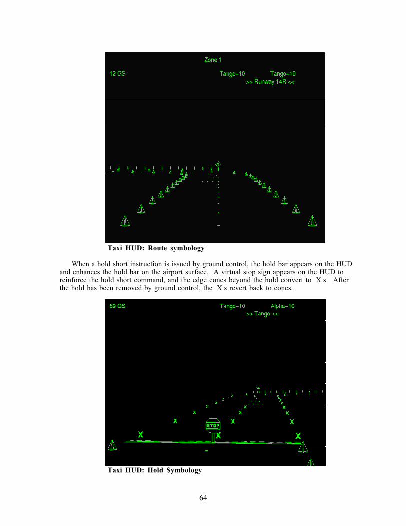
64
Taxi HUD: Route symbology
When a hold short instruction is issued by ground control, the hold bar appears on the HUD
and enhances the hold bar on the airport surface. A virtual stop sign appears on the HUD to
reinforce the hold short command, and the edge cones beyond the hold convert to X s. After
the hold has been removed by ground control, the X s revert back to cones.
Taxi HUD: Hold Symbology
65
How to use the T-NASA Displays:
It is expected that most aircraft will be equipped with one head-up display centered over the
left seat. Therefore only the Captain will have access to the HUD information. However, both
pilots will have their own taxi map located on the navigation displays (ND). Directional audio
alerts will be provided through each pilots headphones. An audio alert from the right side will
indicate that an aircraft is approaching from the right — a left auditory alert will indicate the
threatening traffic is approaching from the left.
Pilots may preview the taxi map while airborne — the overview mode will display the airport
surface layout, as well as runway and concourse location. At least initially, the taxi route will not
be available while airborne.
At touch down, the taxi map perspective mode will automatically appear on the NAV
display. The ROTO HUD will automatically transition to the T-NASA taxi HUD after turning
off the runway.
ATC-Pilot Interaction
• Smart routing algorithms designed to increase productivity and efficiency for airport surface
operations will determine taxi routes.
• In the Near Future:
- After clearing the runway, pilots will call Ground Control (GC) for clearance.
- GC will provide a taxi clearance by voice and send the clearance via datalink to the T-
NASA taxi HUD and taxi map.
- Pilots will acknowledge by voice and datalink response buttons on glare shield.
- All hold and route amendment instructions will be provided by voice and will be
datalinked to the taxi HUD and map in pending form until acknowledged by the flight
crew.
• In the Distant Future:
- The taxi clearance may be datalinked to the T-NASA taxi map while airborne or as
exiting the runway.
- Pilots will acknowledge the route using datalink response buttons on the glare shield.
- At runway turnoff, pilots will continue taxiing, without talking to ground control (except
for emergencies).
- All hold and route amendment instructions will be datalinked directly to the cockpit
accompanied by a datalink message tone, and will appear on the Taxi HUD and taxi map
as pending changes until acknowledged by the flight crew.
66
APPENDIX B - SELECTED COCKPIT PHOTOS OF THE EMB-120AIRCRAFT (SKYWEST CONFIGURATION)
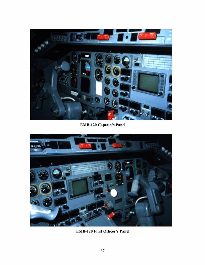
67
EMB-120 Captain’s Panel
EMB-120 First Officer’s Panel
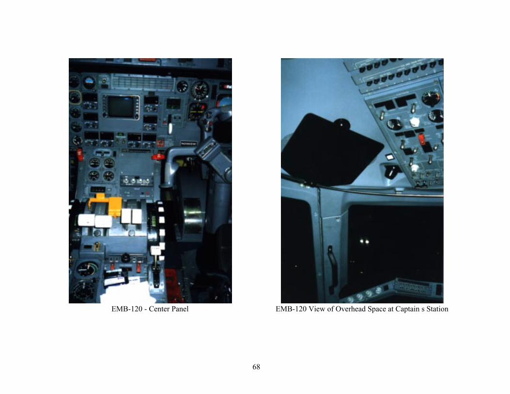
68
EMB-120 - Center Panel EMB-120 View of Overhead Space at Captain s Station
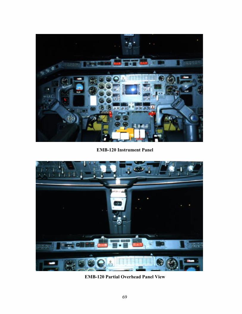
69
EMB-120 Instrument Panel
EMB-120 Partial Overhead Panel View
70
APPENDIX C - SELECTED COCKPIT PHOTOS OF THE MD-87AIRCRAFT (ALASKA AIRLINES CONFIGURATION)
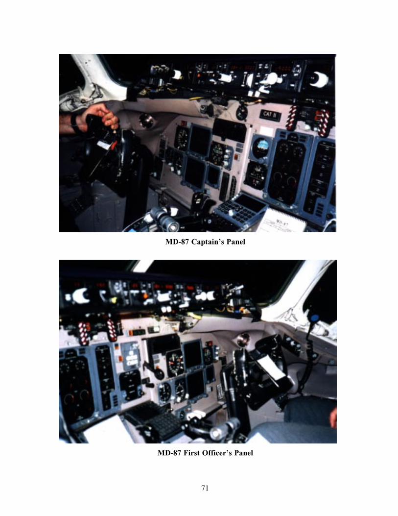
71
MD-87 Captain’s Panel
MD-87 First Officer’s Panel
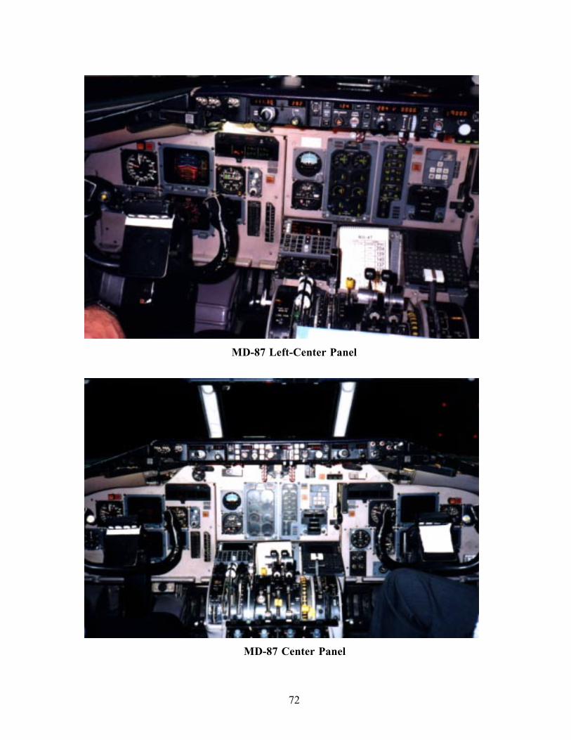
72
MD-87 Left-Center Panel
MD-87 Center Panel
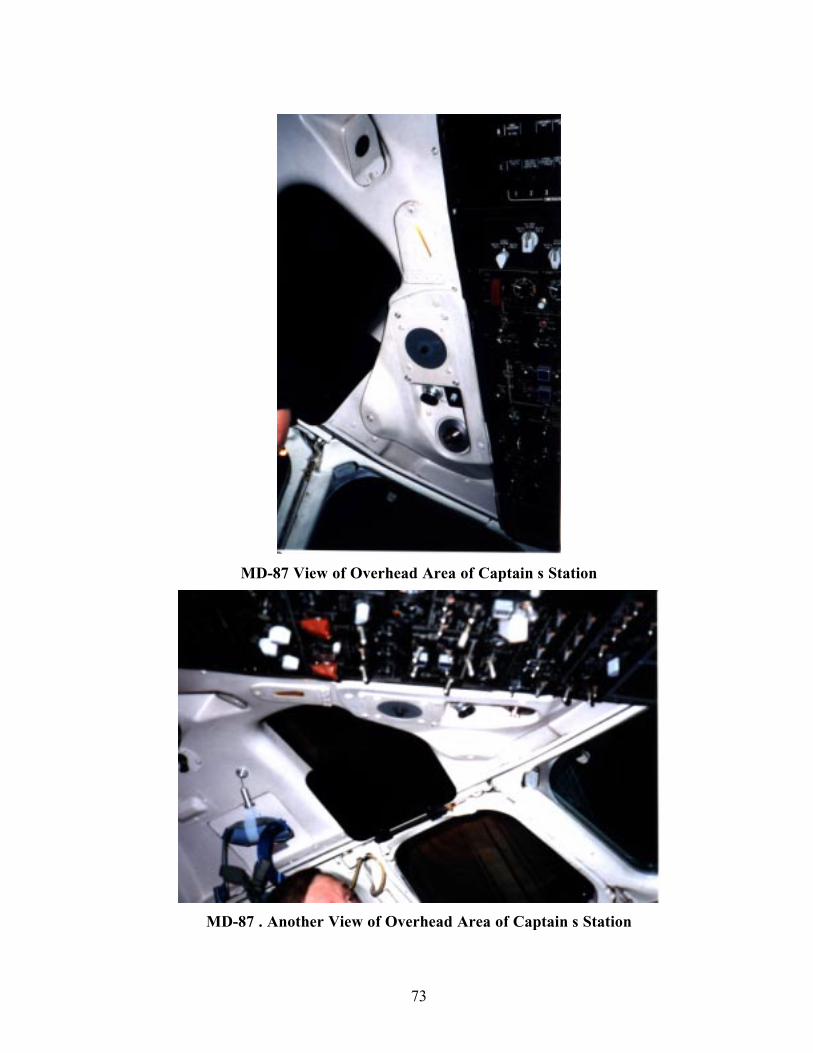
73
MD-87 View of Overhead Area of Captain s Station
MD-87 . Another View of Overhead Area of Captain s Station

74
APPENDIX D - SELECTED COCKPIT PHOTOS OF THE B737-400AIRCRAFT (ALASKA AIRLINES CONFIGURATION)
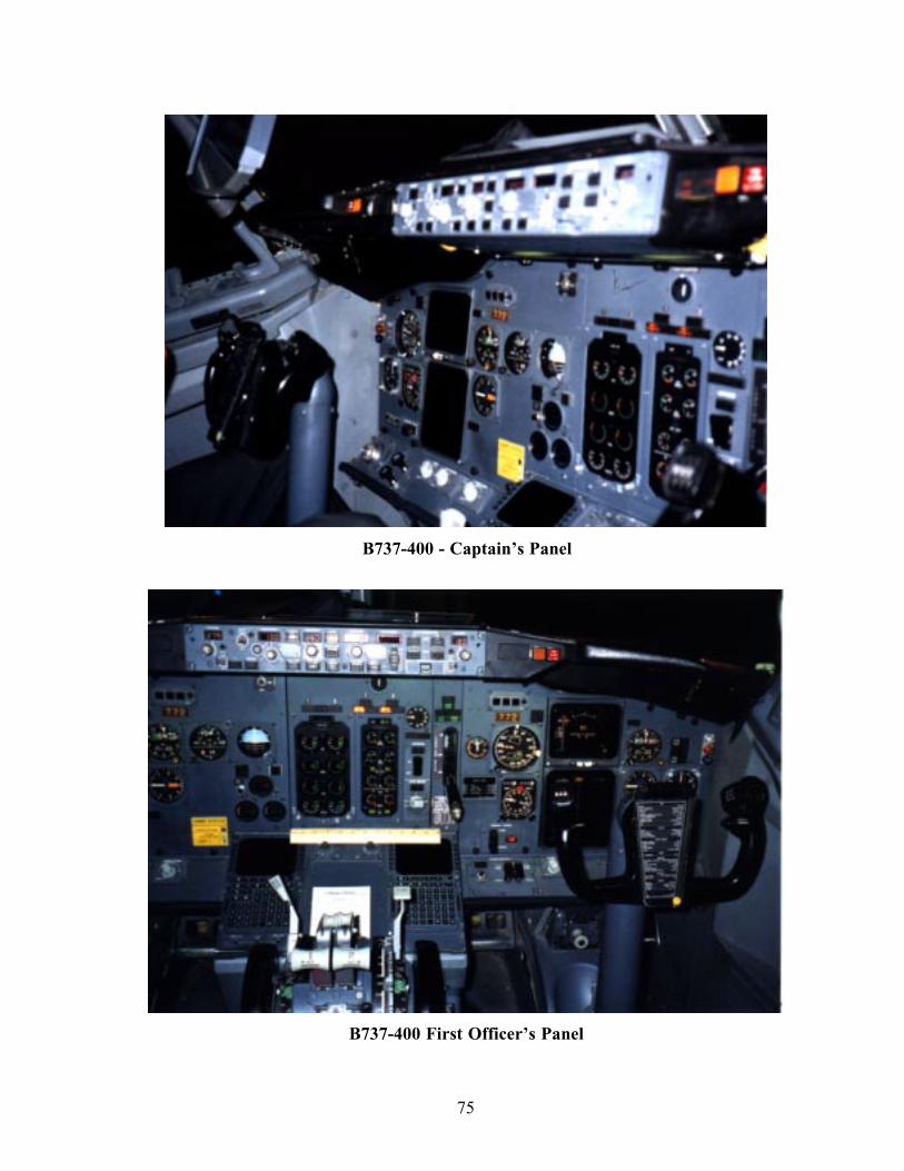
75
B737-400 - Captain’s Panel
B737-400 First Officer’s Panel
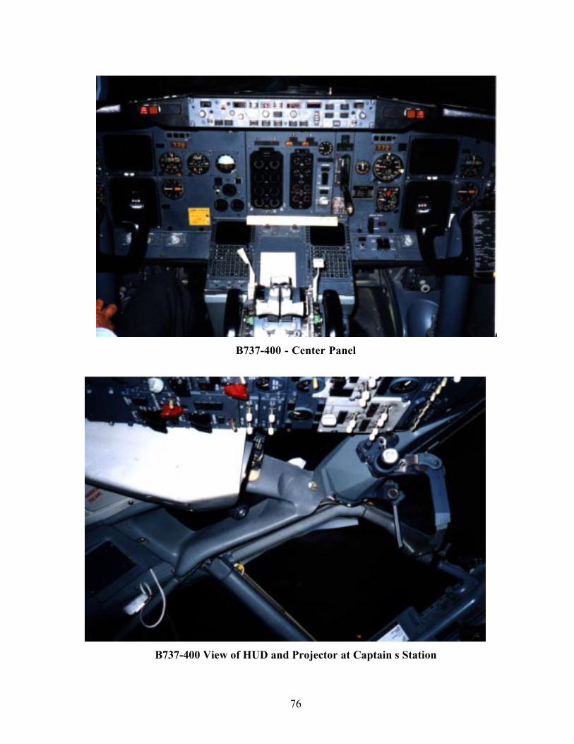
76
B737-400 - Center Panel
B737-400 View of HUD and Projector at Captain s Station
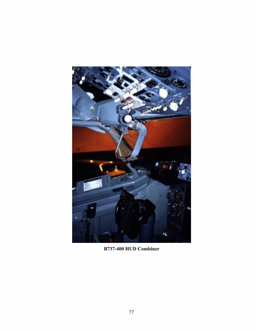
77
B737-400 HUD Combiner
78
APPENDIX E - SELECTED COCKPIT PHOTOS OF THE B747-400AIRCRAFT (CATHAY PACIFIC CONFIGURATION)
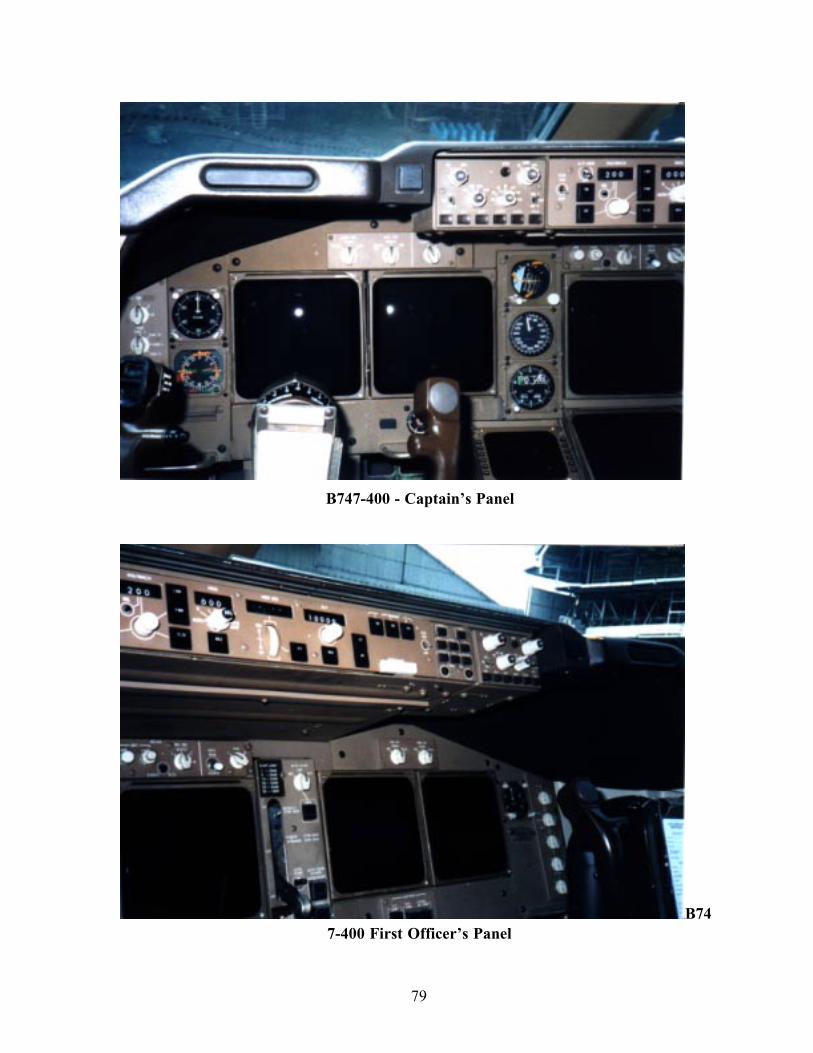
79
B747-400 - Captain’s Panel
B747-400 First Officer’s Panel
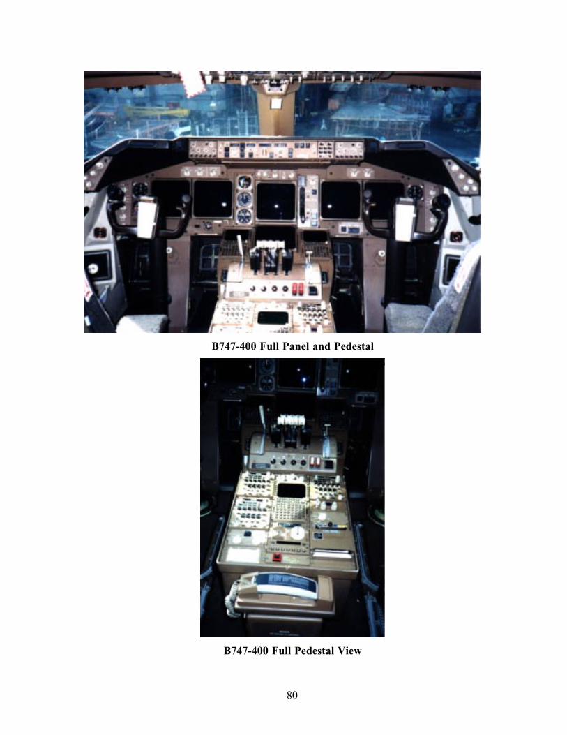
80
B747-400 Full Panel and Pedestal
B747-400 Full Pedestal View
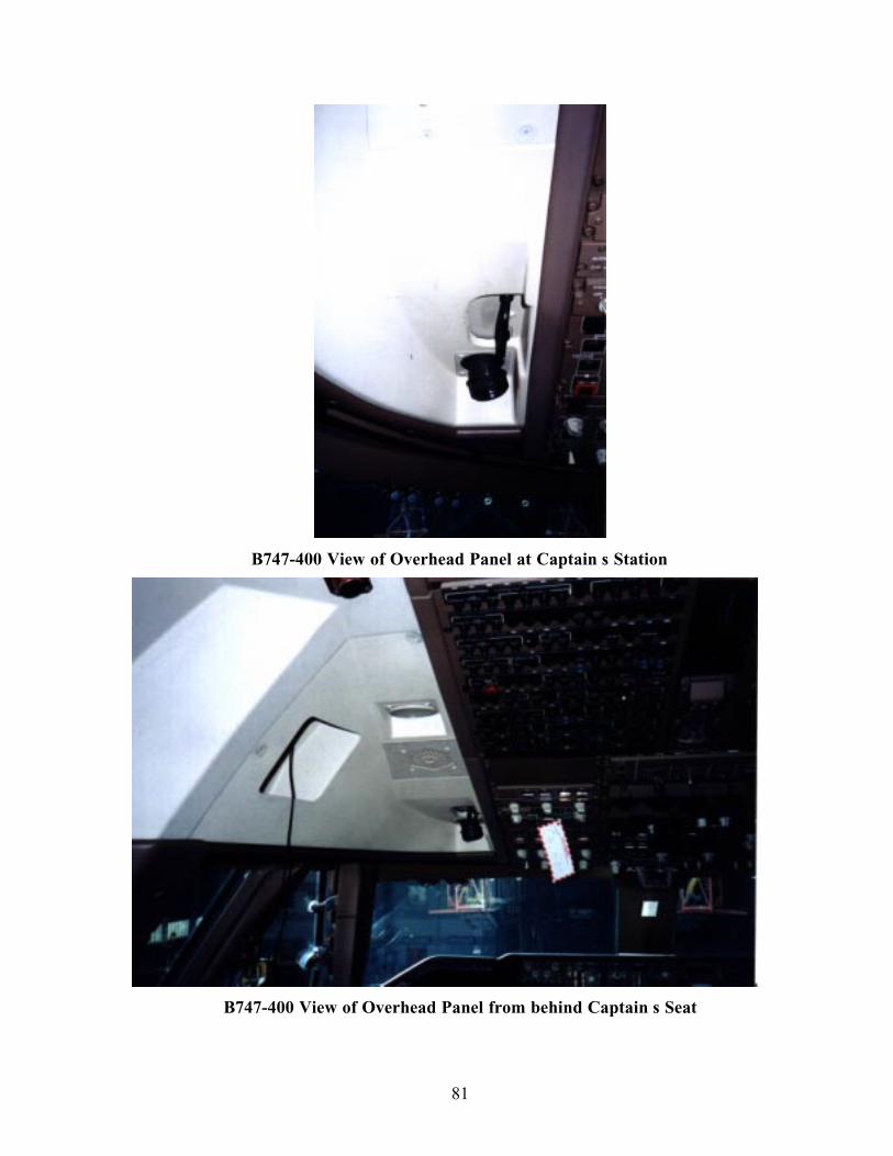
81
B747-400 View of Overhead Panel at Captain s Station
B747-400 View of Overhead Panel from behind Captain s Seat

82
APPENDIX F - SELECTED COCKPIT PHOTOS OF THE B747-200(F)AIRCRAFT (CATHAY PACIFIC AIRWAYS FREIGHTER
CONFIGURATION)
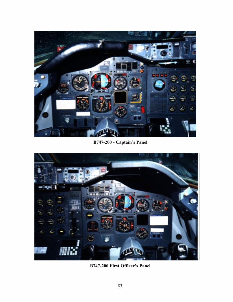
83
B747-200 - Captain’s Panel
B747-200 First Officer’s Panel
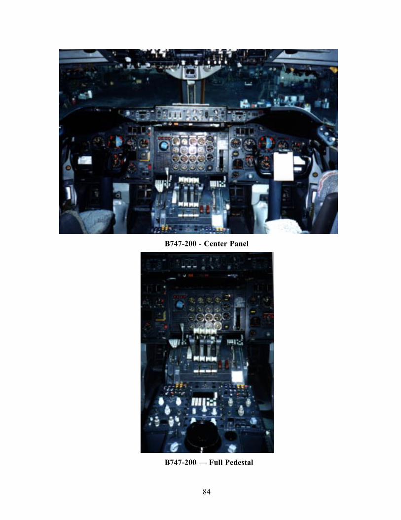
84
B747-200 - Center Panel
B747-200 — Full Pedestal
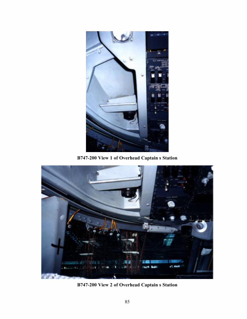
85
B747-200 View 1 of Overhead Captain s Station
B747-200 View 2 of Overhead Captain s Station
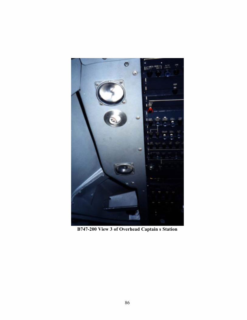
86
B747-200 View 3 of Overhead Captain s Station